

Page 1

CONTENT
F.C.C. statement
Important safeguards
Chapter 1 Introduction
1.2 Features............................................................................................ j
1.3 Checking List.................................................................................... j
Chapter 2 Installation
2.1 Connect your monitor to a computer.
Chapter 3 Overview of your monitor
3.1 Front Panel overview..................................................................... 3
Chapter 4 Operation
4.1 Power ON/OFF switch
4.2 Power indicator................................................................................ 4
4.3 Volume............................................................................................. 4
4.4 Menu features
4.5 OSD menu........................................................................................ ^
4.6 Preset modes timing chart.............................................................. y
Chapter 5 Technical information
5.1 Signal Connector Pin Assignment.................................................. g
5.2 Visual Inspection
5.3 Troubleshooting
..................................................................................
....................................................................
.............................................................................
.................................................................................
...........................................
2
4
4
9
jq
Page 2

FEDERAL COMMUNICATIONS
COMMISSION(F.C.C) STATEMENT
This equipment has been tested and found to eomply with the limits of a Class B
digital device,pursuant to Part 15 of the FCC Rules. These limits are designed to
provide reasonable protection against harmfid interference in a residential
installation. This equipment generates, uses and can radiate radio frequency energy
and, if not installed and used in accordance with the instructions, may cause harmful
interference to radio communications. However, there is no guarantee that
interference will not occur in a particular installation. If this equipment does cause
harmful interference to radio or television reception, which can be determined by
turning the equipment off and on, the user is encouraged to try to correct the
interference by one or more of the following measures:
1. Reorient/Relocate the receiving antenna.
2. Increase the separation between the equipment and receiver.
3. Connect the equipment into an outlet on a circuit different from that to
which the receiver is connected.
4. Consult the dealer of an experienced radio/TV technician for help.
CAUTION: Changes or modifications not expressly approved by the
manufacturer responsible for compliance could void the
user's authority to operate the equipment.
NOTE: The use of a non-shielded interface cable with this equipment
is prohibited.
Page 3

IMPORTANT SAFEGUARDS
Warnings:
1. Read all of these instructions Save these instructions for later use, Please.
2. Ut^lug this monitor from the wall outlet before cleaning. Do not use liquid cleaners or aerosol cleaners. Use a damp cloth for
cleaning.
3. Do not use attachments not recommended by the monitor manu&cturer as they may cause hazards.
4. Do not use this monitor near water. For example near a bathtub, washbowl, kitchen sink, or laundry tub, in a wet basement, or
near a swimming pool, etc...
5. Do not place this monitor on an imstable cart, stand, or table. The monitor may fall, causing serious injury to a child or adult, and
serious damage to the appliance. Use only with a cart or stand recommended by the manufacturer or sold wifri monitor. Wall or
shelf mounting should follow the manu&cturer's instructions, and should use a mounting kit approved by the manufacturer.
6. Slots and openings in the cabinet and the back or bottom are provided for ventilation, and to insure reliable operation of frie
television receiver and to protect it from overheating, these openings must not be blocked or covered. The openings should
never be blocked by placing the monitor on a bed, sofa, rug, or other similar surface. This monitor should never be placed near
or over a radiator or heat register. This monitor should not be placed in built-in installation such as a bookcase unless proper
ventilation is provided.
7. This monitor should be operated only from the type of power source indicated on the marking label. If you are not sure of the
type of power supplied in your home, consult your monitor dealer or local power company.
8. This monitor is equipped with a three-wire groimding type plug, a plug having a third (grounding) pin. This plug will only fît into
groimding-type power outlet This is a safety feature. If you are unable to insert the plug into the outlet, contact your electrician
to replace your obsolete outlet Do not defeat the safety purpose of tiie groimding-type plug.
9. Do not allow anything to rest on tiie power cord. Do not locate tiiis monitor where the cord will be abused by persons working
on it
10. Follow all warnings and instructions marked on tiie monitor.
11 .For added protection for this monitor, when it is left unattended and unused for long periods of time, unplug it from tiie wall
outlet. This will prevent damage to the monitor due to power-line surges.
12. Do not overload wall outlets and extension cords as this can result into fire or electric shock.
13. Never push objects of any kind into this monitor throu^ cabinet slots as they may touch dangerous voltage points or short out
parts that could result in a fîre or electric shock. Never spUl liquid of any kind on the monitor.
14. Do not atten^t to service this monitor yourself since opening or removing covers may eiqiose you to dangerous voltage or
other hazards. Refer all servicing to qualifîed service personnel.
15. Unplug this monitor from the wall outlet and refer servicing to qualifîed service personnel under the following conditions:
a. When tiie power cord or plug is damaged or frayed.
b. If liquid has been spilled into tiie monitor.
c. If tiie monitor has been eiqiosed to rain or water.
d. If the monitor does not operate normally by following the operating instructions. Adjust only those controls that are covered
by the operating instructions as in^rpper adjustment of other controls, may result in damage and wiU often require extensive
work by a quaUfîed technician to restore the monitor to normal operation.
e. If the monitor has been dropped or the cabinet has been damaged.
f When the monitor exhibits a distinct change in performance this indicated a need for service.
16. When replacement parts are required, be sure the service technician has used replacement parts specified by the manufacturer
that have the same characteristics as the original parts. Unauthorized substitutions may result in fîre, electric shock, or other
hazards.
17. Upon completion of any service or repairs to tiiis monitor, ask the service technician to perfonn routine safety checks to
determine that the monitor is in safe operating condition.
1 S.The socket outiet shall be near the equipment and shall be easily accessible.
19.The power supply cord is used as the main disconnect device.
Page 4
Chapter 1
1.1 Features
1. Horizontal frequencies: 31KHz to 80KHz.
Vertical frequencies: 56Hz to 76Hz.
2. Microprocessor based with OSD (On Screen Display) control.
3. Compatible with standard IBM VGA,extended VGA,super VGA, IBM XGA
modes, as well as VESA resolution standards.
4. Universal power supply.
5. Microsoft windows 95/98/2000/ME/XP compatible & VESA Display Data
channel (DDC)1/2B compatible.
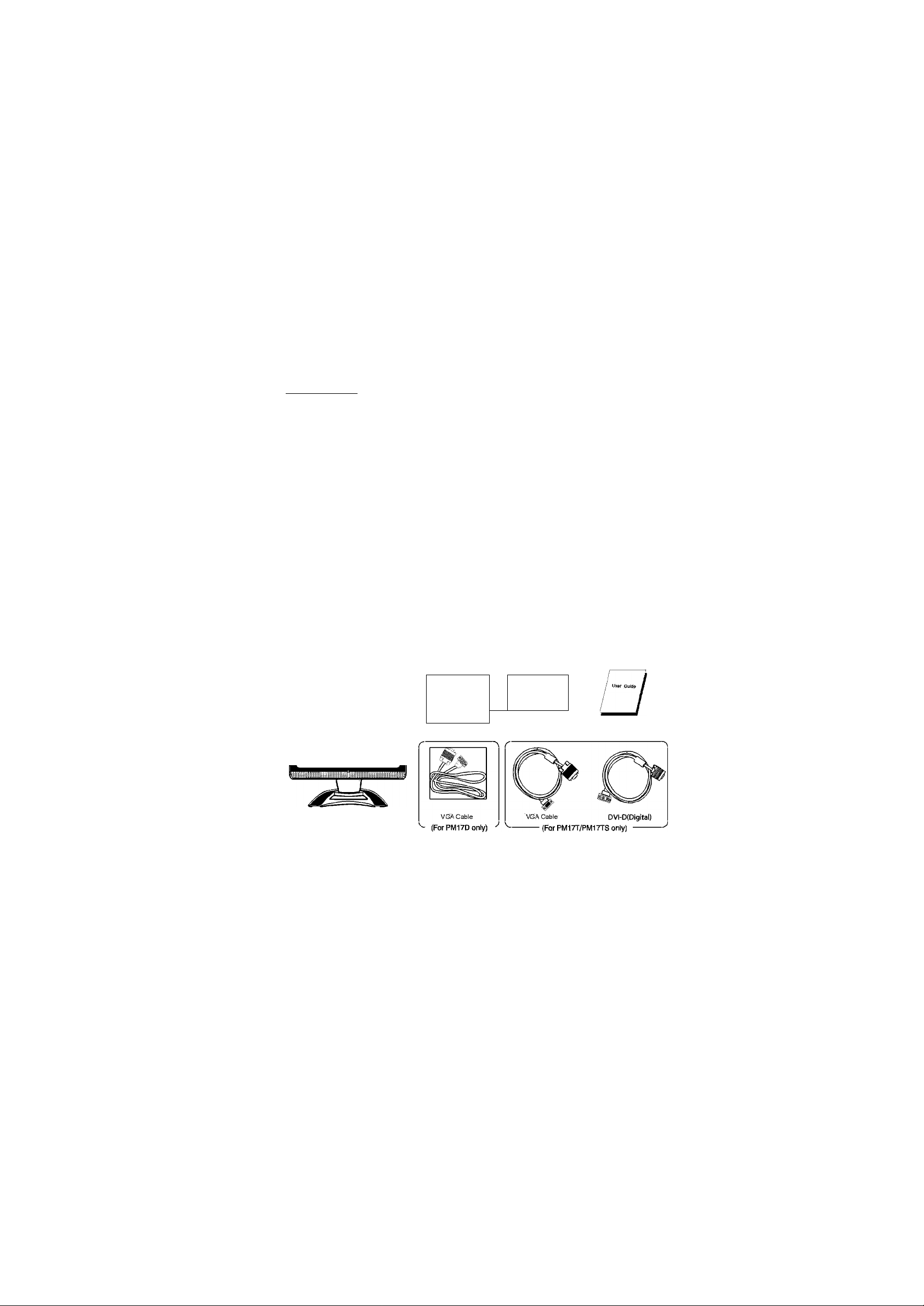
1.2 Checking List
Please make sure the following items are included with your LCD monitor:
• Your monitor • AC power cord
• DC Adapter • Signal cable
• User manual
Introduction
Power Cord
LCD Monitor
If any of these items are missing, please contact with your dealer for
Technical support and customer service.
Note:
Be sure to save original box and all packing material for transport in future if the
Monitor need.
DC Adapter User Guide
Page 5

Chapter 2
Installation
2.1 Connect your monitor to computer
2.1.1 Turn off your computer and unplug its power cable.
2.1.2 Coimect the signal cable to the video port on the back of your computer.
2.1.3 Coimect the power cable for your monitor to the DC adapter and connect
the adapter the DC power jack on the back of your monitor, you must use
the supplied adapter.
2.1.4 Speaker connect one end of the audio cable to the connector on the back
of the monitor audio, and the other end to the sound card of the computer
output.
2.1.5 Plug the computer and monitor power cables into a nearby outlet.
2.1.6 Turn your computer and monitor on, if your monitor display an image, you
have successfully installed the monitor. If the monitor does not display an
Image, check all the connections.
DC IN O Connect to DC Adapter
PM17D
PM17T
PM17TS
Connecting the monitor to the computer and the power supply
00
AUDIO IN 0 Connect to Audio jack (L/R)
VGAIN 0 Connect to VGA Signal Cable
0
DCIN O Connect to DC Adapter
00
AUDIO IN 0 Connect to Audio jack (L/R)
isIHEQid
DVI-DIN 0 Connect to DVI-D or VGA
Signal Cable
VGAIN
Page 6

Chapter 3
3.1 Front Panel overview
Overview of your monitor
VO. ©
-> SET 0
T
©
MEMU 0
©
AUTO O
1. Menu Button
To push menu button turns on the menu, and it activates the items you highlight.
2. Volume Button
To choose which function you need .you may choose + or —
3. Select Button
To choose which function you need .you may choose ▼ counterclockwise or A
Clockwise.
4. Auto Button
Auto adjust the display mode to its utmost performance according to VGA setting.
5. Power Button
Use this button to turn the monitor on and off.
6. Power indicator
Page 7

Chapter 4
OPERATION Direct - Access Features
4.1 SWITCHING THE MONITOR ON/OFF
This ON/OFF button is used for switching the monitor on and off.
Note: The ON/OFF switch does not disconnect the device from the
mains voltage. To completely disconnect the mains voltage.
Please remove the power plug from the socket.
4.2 POWER INDICATOR
This indicator lights up green(PM17T/D)/blue(PM17TS) when the monitor
operates normally.If the monitor is in power saving mode, this indicator change
to orange. When monitor is turn off, this indicator change the color to dark.
4.3 VOLUME
This feature adjust the DOWN button to decrease the volume and
UP button to increase the volume.
Important information on andio piayback
To achieve optimum sound quality from the monitor speakers,
the audio cable should be connected to the Line-Out socket
(headphone socket) of the computer. If you connect the audio cable
to the Speaker-Out socket (soundcard) of the computer. Please set
the volume under Windows to range between 20% - 40% of the
maximum value to achieve optimum sound quality.
_____________
4.4 MENU FEATURES
The following features can all he accessed by using your monitor's on
screen menu system. Once are finished. Making adjustments to a feature,
selecting the exit icon to turn off the menu.
Please follow the procedure of selection and adjust an item using the OSD
system as below steps for main functions adjustment.
Step 1: Press the MENU button to activate the OSD menu.
Step 2: If necessary, use the A or ▼ button to mark an
Step 3: Press the MENU button to activate the highlighted icon.
Step 4: Use the A or ▼ button to make the desired setting.
Step 5: Select the EXIT symbol to exit the OSD menu.
Step 6: Repeat step 2 through 5 to make further adjustments.
All changes are stored immediately
The main menu appears on the screen with icons for the
setting functions.
other icon.
Page 8

OPERATION Direct - Access Features
4.5 OSD MENU
1. Main menu
OSD main menu of controls gives you an overview of the selection of controls
available. When you want to make adjustment of the screen image, press and
release button Menu
1024x768
C»
o
CË]
O
3* EXIT
©
H=60.0KHz u^75.1Hz
2. OSD Adjustment
You can choose where you would like OSD image to appear on your screen.
H-Position : &
To move the OSD image horizontally left or right.
V-Position : Q
To move the OSD image vertically up or down.
£xit: ixiti
To exit the sub menu
3. Language
You can choose one of the seven language you need.
4. Reset
Reset the currently highlighted control to the factory setting. User must be using
factory preset video mode to use this ftmction.
5. Auto ® / 25 (SETUP)
Auto adjust display mode to its utmost performance according to VGA setting.
In the event of die display image needs further adjustment.
Page 9

OPERATION Direct - Access Features
\ SET UP select menu. (Only for PM17T/PM17TS)
1. Input Seleet
You can choose the signal input status which you need.
2. AUTO Select
Auto adjust display mode to its utmost performance aceording to VGA setting.
In the event of the display image needs further adjustment. In addition, press this
key for more than three seconds, the input signal can be realized switching over
automatically.
6. Color Select
Color Select Menu
B*
COOL NATURAL WARM
Select user mode MIHIHiiaaiHl
User eolor you ean adjust to individual color gum intensity hy yourself Inerease or
decrease red. green or blue depending upon which color is selected.
COOL: This control adjusts the color temperature of the sereen image. This item are preset
by factory, you can not adjust these setting. The performance is bluer and brighter.
WARM: The performance is redder and closer to paper white.
NATURAL: to give the white color a natural tint.
7. Phase
To improve focus clarity an image stability.
8. H. Size O
To increase or deerease the horizontal size of image.
9. V. Position o
To move the picture image vertically up or down.
10. H. Position [
To move the picture image horizontally left or right.
11. Contrast o
Adjust the image brightness in relation to the background.
12. Brightness
Adjust the overall image and background screen brightness.
Page 10

Chapter 4
4.6 Preset Modes Timing Chart
OPERATION Direct - Access Features
Item
1 720 X400 31.47 70
2 640 X480 31.47 60
3 640 X480 37.86 72.8
4
5
6
7 800 X600 48.08
8
9
10
11
12
13
Resolution
(dots X lines)
640 X480 37.50
800 X600 35.15 56.2
800 X600 37.88 60.3
800 X600 46.87 75
1024 X 768
1024 X 768
1024 X 768 60.02
1280 X 1024
1280 X 1024 80
Horizontal
Freq.(kHz)
48.36
56.48 70.1
63.98 60
Vertical
Freq.(Hz)
75
72.2
60
75
75
Page 11

Chapter 5
5.1 Signal connector pin assignment
1. PM17D/PM17T/PM17TS
PIN Signal (D-sub) PIN Signal (D-sub)
1
Red 9 NC or-1-5 V Input
2 Green
3 Blue
4
Ground
5 Self Test 13 H. Sync
6
Red Ground
7 Green Ground 15 SCL (FOR DDC)
8 Blue Ground
10 Ground
11
Ground
12
SDA (FOR DDC)
14
V. Sync
Technical Information
15-Pin mini D-iype male connector
Page 12

Chapter 5
2. PM17T/PM17TS
Technical Information
Signal (DVI)
PIN
1 TMDS Data 2- 16 Hot Plug Detect
2 TMDS Data 2+ 17 TMDS Data 03 TMDS Data 2/4 shield 18 TMDS Data 0+
4
TMDS Data 4- 19 TMDS Data 0/5 shield
5 TMDS Data 4+ 20 TMDS Data 5-
DDC Clock 21
6
7 DDC Data
8 Analog Vertical Synchronal 23 Clock +
TMDS Data 1- 24
9
10 TMDS Data 1+
11 TMDS Data 1/3 shield
12 TMDS Data 313 TMDS Data 3+
14 +5V Power
15 Ground
PIN
22
Signal (DVI)
TMDS Data 5+
Clock shield
Clock -
5.2 Visual Inspection
Even the normal pixels on the LCD screen reach 99.99% or higher, there
maybe0.01%orlesspixelsshowingdark or light while displaying.
Page 13

Technical Information
5.3 Trouble shooting
Before calling for service , check the information in this section to see if you
can remedy any problems by yourself. If you need assistance, please call the
dealer where you purchased the LCD monitor.
There is no SCREEN image
Please cheek these items:
• The power cord is securely connected the monitor, the adaptor, and
the waU outlet
• Check the signal cable connection between the monitor and the
computer.
• Adjust the brightness and contrast controls.
• Monitor in power saving mode.
Display image is too large or small
• Use the OSD controls to adjust Auto Setup.
The colors are discord
• Signal cable properly connected?
• Use OSD controls to adjust the color control setting.
The image is too light or too dark
• Use OSD controls to adjust the brightness and contrast.
There is no sound or sound is low
• Check the audio cable connector.
• Make sure the computer sound program is working.
• Change the volume on sound setting. Adjust your sound card or computer
volume setting.
For applicable power supplies see user instructions!
Adapter Suppliers:
1. Li Shin: LSE9901B1250
2. Linearity: LAD6019AB4
3. Lien Chang: LCAOIF
4. FSP Group Inc: FSP048-1AD101C
5. Medi Power: AD-1250B
10
 Loading...