

Asus J34551-CM-A User manual

J3455I-CM-A
Industrial Motherboard

E16639
First Edition
May 2020
Copyright © 2020 ASUSTeK COMPUTER INC. All Rights Reserved.
No part of this manual, including the products and software described in it, may be reproduced,
transmitted, transcribed, stored in a retrieval system, or translated into any language in any form or by any
means, except documentation kept by the purchaser for backup purposes, without the express written
permission of ASUSTeK COMPUTER INC. (“ASUS”).
Product warranty or service will not be extended if: (1) the product is repaired, modied or altered, unless
such repair, modication of alteration is authorized in writing by ASUS; or (2) the serial number of the
product is defaced or missing.
ASUS PROVIDES THIS MANUAL “AS IS” WITHOUT WARRANTY OF ANY KIND, EITHER EXPRESS
OR IMPLIED, INCLUDING BUT NOT LIMITED TO THE IMPLIED WARRANTIES OR CONDITIONS OF
MERCHANTABILITY OR FITNESS FOR A PARTICULAR PURPOSE. IN NO EVENT SHALL ASUS, ITS
DIRECTORS, OFFICERS, EMPLOYEES OR AGENTS BE LIABLE FOR ANY INDIRECT, SPECIAL,
INCIDENTAL, OR CONSEQUENTIAL DAMAGES (INCLUDING DAMAGES FOR LOSS OF PROFITS,
LOSS OF BUSINESS, LOSS OF USE OR DATA, INTERRUPTION OF BUSINESS AND THE LIKE),
EVEN IF ASUS HAS BEEN ADVISED OF THE POSSIBILITY OF SUCH DAMAGES ARISING FROM ANY
DEFECT OR ERROR IN THIS MANUAL OR PRODUCT.
SPECIFICATIONS AND INFORMATION CONTAINED IN THIS MANUAL ARE FURNISHED FOR
INFORMATIONAL USE ONLY, AND ARE SUBJECT TO CHANGE AT ANY TIME WITHOUT NOTICE,
AND SHOULD NOT BE CONSTRUED AS A COMMITMENT BY ASUS. ASUS ASSUMES NO
RESPONSIBILITY OR LIABILITY FOR ANY ERRORS OR INACCURACIES THAT MAY APPEAR IN THIS
MANUAL, INCLUDING THE PRODUCTS AND SOFTWARE DESCRIBED IN IT.
Products and corporate names appearing in this manual may or may not be registered trademarks or
copyrights of their respective companies, and are used only for identication or explanation and to the
owners’ benet, without intent to infringe.
Offer to Provide Source Code of Certain Software
This product contains copyrighted software that is licensed under the General Public License (“GPL”),
under the Lesser General Public License Version (“LGPL”) and/or other Free Open Source Software
Licenses. Such software in this product is distributed without any warranty to the extent permitted by the
applicable law. Copies of these licenses are included in this product.
Where the applicable license entitles you to the source code of such software and/or other additional data,
you may obtain it for a period of three years after our last shipment of the product, either
(1) for free by downloading it from https://www.asus.com/support/
or
(2) for the cost of reproduction and shipment, which is dependent on the preferred carrier and the location
where you want to have it shipped to, by sending a request to:
ASUSTeK Computer Inc.
Legal Compliance Dept.
1F., No. 15, Lide Rd.,
Beitou Dist., Taipei City 112
Taiwan
In your request please provide the name, model number and version, as stated in the About Box of the
product for which you wish to obtain the corresponding source code and your contact details so that we
can coordinate the terms and cost of shipment with you.
The source code will be distributed WITHOUT ANY WARRANTY and licensed under the same license as
the corresponding binary/object code.
This offer is valid to anyone in receipt of this information.
ASUSTeK is eager to duly provide complete source code as required under various Free Open Source
Software licenses. If however you encounter any problems in obtaining the full corresponding source
code we would be much obliged if you give us a notication to the email address gpl@asus.com, stating
the product and describing the problem (please DO NOT send large attachments such as source code
archives, etc. to this email address).
ii

Contents
Chapter 1 Product overview
1.1 Package contents......................................................................... 1-1
1.2 Features ........................................................................................ 1-1
1.3 Specifications ............................................................................... 1-2
Chapter 2 Motherboard information
2.1 Before you proceed ..................................................................... 2-1
2.2 Motherboard layout ...................................................................... 2-2
2.3 Central Processing Unit (CPU) ................................................... 2-4
2.4 System memory ........................................................................... 2-4
2.5 Jumpers ........................................................................................ 2-7
2.6 Connectors ................................................................................. 2-10
2.6.1 Rear panel connectors .................................................. 2-10
2.6.2 Internal connectors ....................................................... 2-12
Chapter 3 BIOS setup
3.1 BIOS setup program .................................................................... 3-1
3.2 My Favorites ................................................................................. 3-3
3.3 Main menu .................................................................................... 3-4
3.3.1 System Language [English] ............................................ 3-4
3.3.2 System Date [Day xx/xx/xxxx] ......................................... 3-4
3.3.3 System Time [xx:xx:xx] ................................................... 3-4
3.3.4 Security ........................................................................... 3-4
3.4 Advanced menu ........................................................................... 3-6
3.4.1 LVDS Conguration ........................................................ 3-6
3.4.2 Onboard Devices Conguration ...................................... 3-8
3.4.3 APM ................................................................................ 3-9
3.4.4 CPU Conguration ........................................................ 3-10
3.4.5 Network Stack Conguration ........................................ 3-11
3.4.6 USB Conguration ........................................................ 3-11
3.4.7 Platform Trust Technology ............................................ 3-12
3.4.8 SoC Conguration ......................................................... 3-12
3.4.9 SATA Conguration ...................................................... 3-12
3.5 Monitor menu ............................................................................. 3-14
3.5.1 CPU/MB/ Temperature [xxxºC/xxxºF] ........................... 3-14
3.5.2 CPU / Chassis Fan Speed [xxxx RPM] or [Ignore] / [N/A] 3-14
iii

3.5.3 CPU Core Voltage, 3.3V Voltage, 5V Voltage, 12V Voltage 3-14
3.5.4 CPU Q-Fan Control [Enabled] ...................................... 3-14
3.5.5 Chassis Q-Fan Control [Enabled] ................................. 3-15
3.6 Boot menu .................................................................................. 3-17
3.6.1 Fast Boot [Enabled] ...................................................... 3-17
3.6.2 Boot Logo Display [Enabled] ......................................... 3-17
3.6.3 Bootup NumLock State [On] ......................................... 3-18
3.6.4 Wait for ‘F1’ If Error [Enabled] ....................................... 3-18
3.6.5 CSM (Compatibility Support Module) ............................ 3-18
3.6.6 Secure Boot .................................................................. 3-19
3.7 Tool menu ................................................................................... 3-21
3.7.1 ASUS EZ Flash 3 Utility ................................................ 3-21
3.7.2 ASUS User Prole ........................................................ 3-21
3.8 Exit menu .................................................................................... 3-22
Appendix Notices
ASUS contact information .......................................................................A-5
iv
Chapter 1
Product overview
1.1 Package contents
Check your industrial motherboard package for the following items.
1 x ASUS J3455I-CM-A Motherboard
1 x Serial ATA 6.0 Gb/s cables
2 x M.2 screw packages
1 x ASUS I/O Shield
NOTE: If any of the above items is damaged or missing, contact your
distributor or sales representative immediately.
1.2 Features
• Built-in Intel® Celeron® Quad-core Processor J3455
• Two DDR3L 1866/1600/1333 MHz Non-ECC Un-buffered U-DIMMs up to 8GB
• 2 x SATA 6Gb/s, 6 x USB 3.2 Gen 1, 4 x USB 2.0, 2 x COM headers
• 1 x PCIe 2.0 x4 slot (x1 mode), 1 x M.2 Socket 1 with E key
• Multi-display: 1 x VGA, 1 x HDMI, 1 x LVDS, HDMI + VGA + LVDS
Chapter 1: General information
1-1
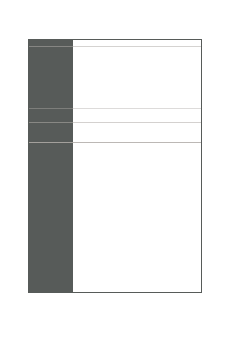
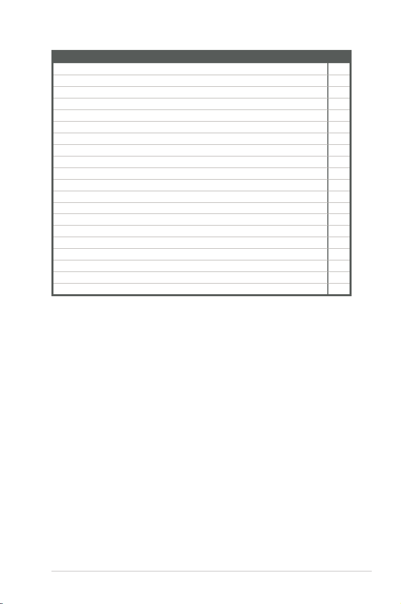
1.3 Specifications
CPU
Memory
Graphics
Expansion slots
Storage 2 x SATA Gen3.0 up to 6.0 Gb/s ports
Ethernet
Audio Realtek® ALC887-VD2 High Denition Audio
Rear panel I/O
ports
Internal
Connectors
Built-in Intel® Celeron® Quad-core Processor J3455
2 x DDR3L, max.8GB, DDR3L 1866/1600/1333 MHz Non-ECC,
Unbuffered Memory
Integrated graphics processor - Intel® HD Graphics support
- Supports VGA output with a maximum resolution of 1920 x
1200 @ 60Hz
- Supports HDMITM output with a maximum resolution of 3840
x 2160 @ 30Hz
- Supports LVDS output with a maximum resolution of 1920 x
1200 @ 60Hz
Support up to three displays simultaneously
1 x PCI Express 2.0 x4 slot (x1 mode)
1 x M.2 Socket 1 with E key, type 2230 for WIFI/BT device
1 Realtek® 8111H
1 x VGA port
1 x HDMITM port
4 x USB 3.2 Gen 1 ports
1 x Serial port (RS232)
1 x LAN (RJ45) ports
1 x P/S2 keyboard port
1 x P/S2 mouse port
3 x Audio jacks
1 x Serial Port header (1 x RS232)
1 x CPU Fan header (PWM Mode)
1 x Chassis Fan header (PWM + DC Mode)
1 x Chassis intrusion header
1 x Front panel audio header (AAFP)
1 x System panel header (10-1 pin)
1 x Clear CMOS jumper
1 x Buzzer
1 x LVDS header
1 x Display Panel Backlight power selection header
1 x Flat Panel Display Brightness selection header
1 x USB 3.2 Gen 1 header supports additional 2 USB 3.2 Gen 1
ports
1-2
(continued on the next page)
J3455I-CM-A
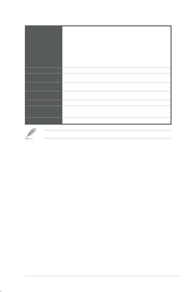
2 x USB 2.0 headers support additional 4 USB 3.2 Gen 1 ports
1 x Parallel Port header
Internal
Connectors
Manageability
Power
requirement
Operation
Temperature
Non-Operation
Temperature
Relative Humidity 0%~85%
OS support
Form Factor
NOTE: Specications are subject to change without notice.
1 x LPC TPM header
1 x Display Panel VCC Power selection header
1 x LCD panel monitor switch header
1 x 24-pin EATX power connector
1 x 4-pin ATX 12V power connector
WfM 2.0, WOL by PME
ATX mode
0~50°C
-40~75°C
Windows® 10 (64bit)
Ubuntu, RedHat Enterprise, Fedora Workstation, OpenSUSE
Mini-ITX Form Factor, 6.7”x 6.7” (17.0cm x 17.0cm)
Chapter 1: General information
1-3

Chapter 2
Motherboard information
2.1 Before you proceed
Take note of the following precautions before you install motherboard components
or change any motherboard settings.
CAUTION!
• Unplug the power cord from the wall socket before touching any
component.
• Before handling components, use a grounded wrist strap or touch a safely
grounded object or a metal object, such as the power supply case, to avoid
damaging them due to static electricity.
• Hold components by the edges to avoid touching the ICs on them.
• Whenever you uninstall any component, place it on a grounded antistatic
pad or in the bag that came with the component.
• Before you install or remove any component, always remove the AC power
by unplugging the power cord from the power outlet. Failure to do so may
cause severe damage to the motherboard, peripherals, or components.
Chapter 2: Motherboard information
2-1
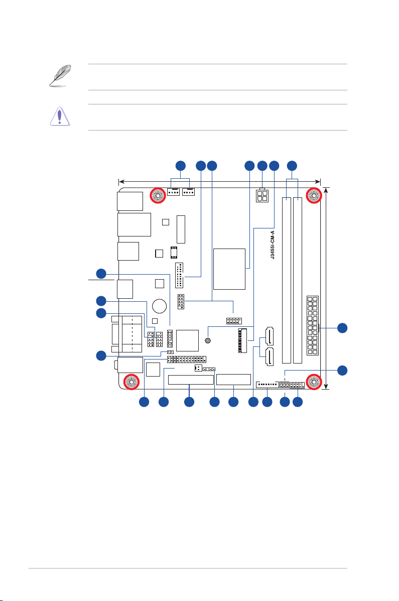
2.2 Motherboard layout
NOTE: Place four screws into the holes indicated by circles to secure the
motherboard to the chassis.
CAUTION! Do not overtighten the screws! Doing so can damage the
motherboard.
4 5 6321 7
17.0cm(6.7in)
Place this side
towards the rear
of the chassis
ASM
1042A
ASM
1442K
BUZZER
COM2
CHA_FANCPU_FAN
RTL
8111H
BATTERY
128Mb
BIOS
Intel
J3455
U32G1_12
USBE12
RTD
2166
TPM
Super
I/O
PANEL_SW
PCIEX4
2230
LPT
CHASSIS
CLRTC
USB56
LVDS
ATX12V
®
17.0cm(6.7in)
DDR3 DIMM_A1 (64bit, 240-pin module)
M.2_(WIFI)
LCD_BLKT_PANEL
DDR3 DIMM_B1 (64bit, 240-pin module)
EATXPWR
SATA6G_1SATA6G_2
VCC_PWR_SEL
F_PANEL
BLKT_PWR_SEL
5
8
KBMS
LAN_U32G1_34
U32G1_E12
21
HDMI
20
19
VGA
COM1
AUDIO
AAFP
ALC
887
18
14 101113 12 916 1517
2-2
J3455I-CM-A
Connectors/Jumpers/Slots
1. CPU and chassis fan headers (4-pin CPU_FAN, 4-pin CHA_FAN) 2-12
2. USB 3.2 Gen 1 header (20-1 pin U32G1_12) 2-12
3. USB 2.0 headers (10-1pin USB_E12, USB56) 2-13
4. Built-in Intel® Celeron® Quad-core Processor J3455 2-4
5. ATX power connectors (24-pin EATXPWR, 4-pin ATX12V) 2-14
6. M.2 Wi-Fi 2-14
7. DDR3L DIMM slots 2-4
8. Display panel VCC power selection (3-pin VCC_PWR_SEL) 2-8
9. System panel header (10-1 pin F_PANEL) 2-15
10. Display panel backlight power selection (3-pin BLKT_PWR_SEL) 2-9
11. Flat panel display brightness header (8-pin LCD_BLKT_PANEL) 2-16
12. SATA connectors (7-pin SATA6G_1, SATA6G_2) 2-16
13. LVDS connector (40-pin LVDS) 2-17
14. Chassis Intrusion header (4-1 pin CHASSIS) 2-8
15. Panel switch (2-pin PANEL_SW) 2-17
16. LPT connector (26-1 pin LPT) 2-18
17. Clear RTC RAM (2-pin CLRTC) 2-7
18. Front panel audio header (10-1 pin AAFP) 2-18
19. Serial port header (10-1 pin COM2) 2-19
20. TPM header (14-1 pin TPM) 2-19
Page
Chapter 2: Motherboard information
2-3
2.3 Central Processing Unit (CPU)
The motherboard comes with an onboard Intel
®
Celeron® Quad-core processor J3455.
®
Intel
J3455
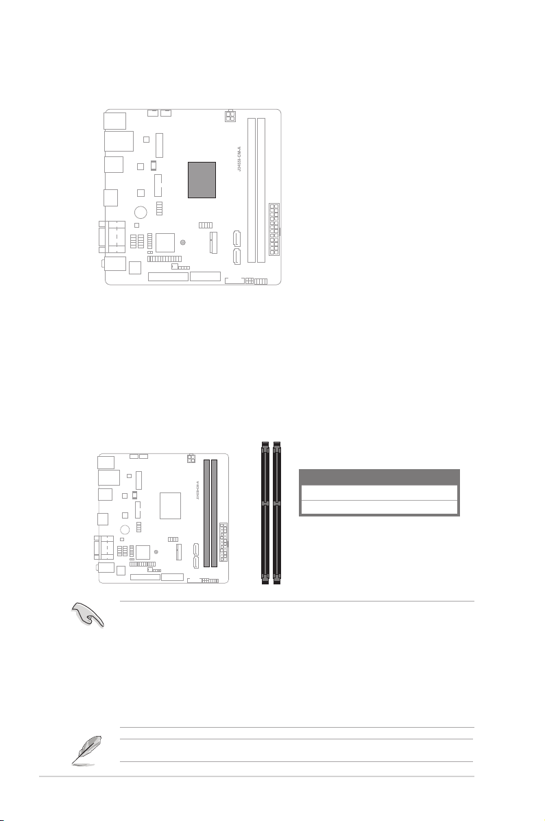
2.4 System memory
This motherboard comes with two Double Data Rate 3 (DDR3) Dual Inline Memory Module
(DIMM) sockets. The gure illustrates the location of the DDR3 DIMM sockets:
2-4
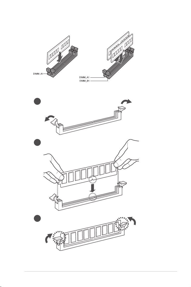
DIMM_A1
DIMM_B1
• You may install varying memory sizes in Channel A and Channel B. The system maps
the total size of the lower-sized channel for the dual-channel conguration. Any excess
memory from the higher-sized channel is then mapped for single-channel operation.
• Always install the DIMMS with the same CAS Latency. For an optimum compatibility,
we recommend that you install memory modules of the same version or data code
(D/C) from the same vendor. Check with the vendor to get the correct memory
modules.
• According to Intel® CPU spec, DIMM voltage below 1.35V is recommended to protect
the CPU.
Visit the ASUS website at www.asus.com for the latest QVL.
Channel Sockets
Channel A DIMM_A1
Channel B DIMM_B1
J3455I-CM-A
Recommended memory configuration
Installing a DIMM
1
2
3
Chapter 2: Motherboard information
2-5
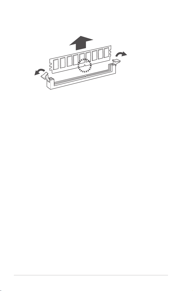
To remove a DIMM
2-6
J3455I-CM-A
2.5 Jumpers
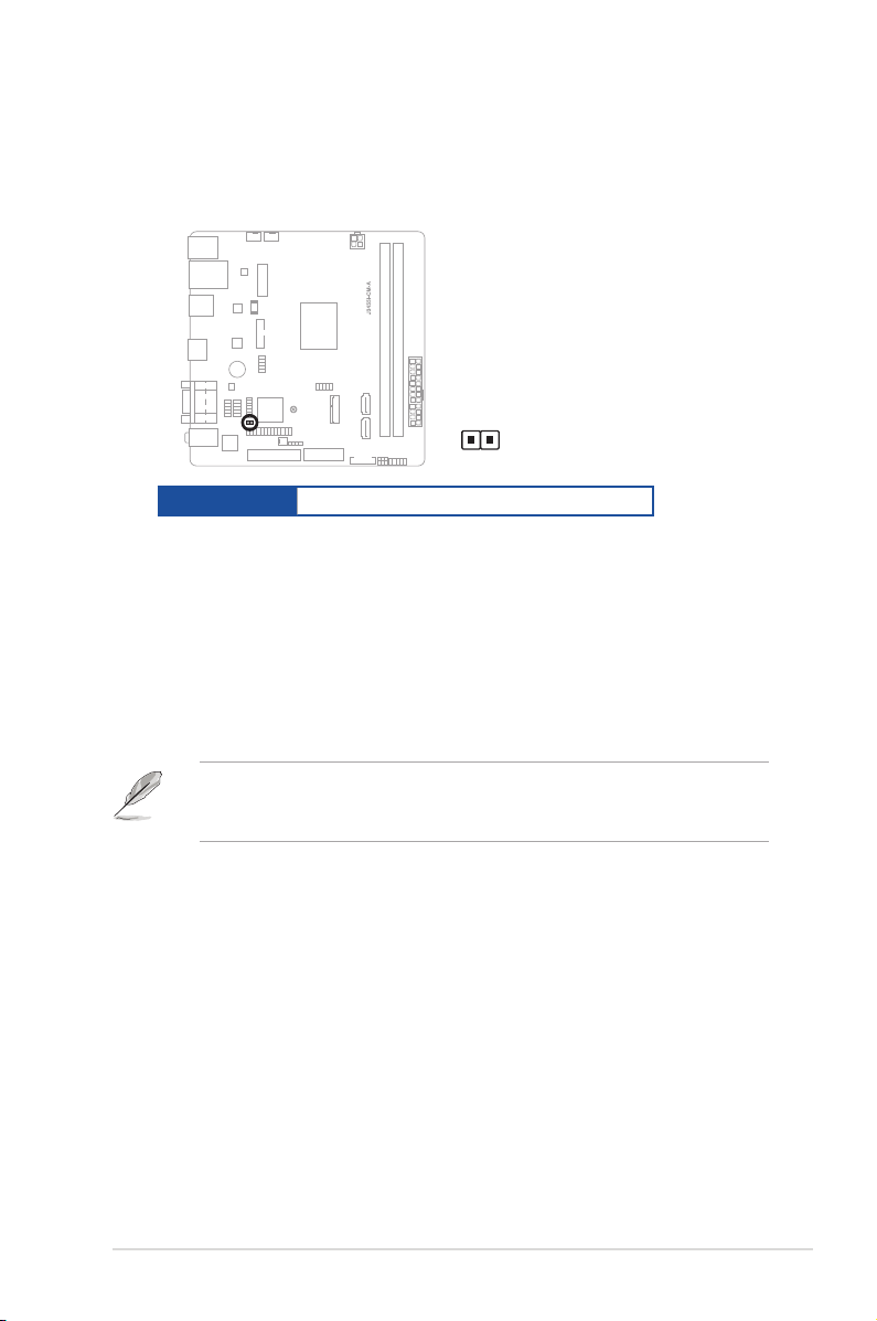
1. Clear RTC RAM (2-pin CLRTC)
This header allows you to clear the CMOS RTC RAM data of the system
setup information such as date, time, and system passwords.
CLRTC
Connector type
HEADER 1x2p, 2.54mm pitch, S/T
To erase the RTC RAM:
1. Turn OFF the computer and unplug the power cord.
2. Use a metal object such as a screwdriver to short the two pins.
3. Plug the power cord and turn ON the computer.
4. Hold down the <Del> key during the boot process and enter BIOS setup
to re-enter data.
NOTE: If the steps above do not help, remove the onboard battery and move
the jumper again to clear the CMOS RTC RAM data. After clearing the CMOS,
reinstall the battery.
Chapter 2: Motherboard information
2-7
2. Chassis intrusion header (4-1 pin_CHASSIS)
PIN 1
+5VSB_MB
Chassis Signal
GND
CHASSIS
1 2
2 3
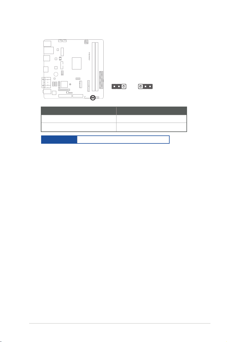
+3V LCD_VCC
(Default)
LCD_VCC +5V
VCC_PWR_SEL
This header is for a chassis-mounted intrusion detection sensor or switch. Connect
one end of the chassis intrusion sensor or switch cable to this connector. The
chassis intrusion sensor or switch sends a low-level signal to this connector
when a chassis component is installed. The signal is then generated as a chassis
intrusion event.
Connector type
HEADER 4p, K2, 2.54mm pitch
3. Display panel VCC power selection (3-pin VCC_PWR_SEL)
Setting Pins
3.3V (Default) 1-2
5V 3-4
Connector type
HEADER 1 x 3p, 2.54mm pitch, S/T
2-8
J3455I-CM-A
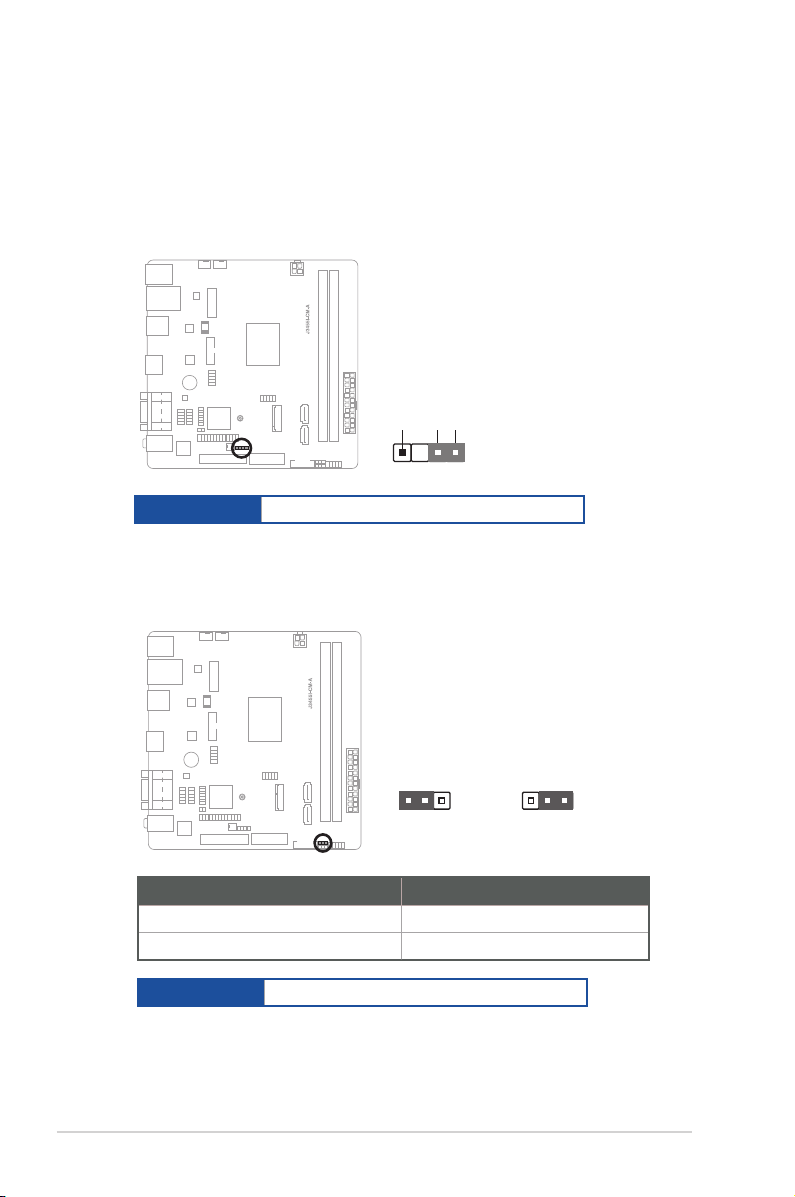
4. Display panel backlight power selection (3-pin BLKT_PWR_SEL)
1 2
2 3
12V
(Default)
5V
BLKT_PWR_SEL
Pins
12V (Default) 1-2
5V 2-3
Connector type
HEADER 1x3p, 2.54mm pitch, S/T
Chapter 2: Motherboard information
2-9
2.6 Connectors
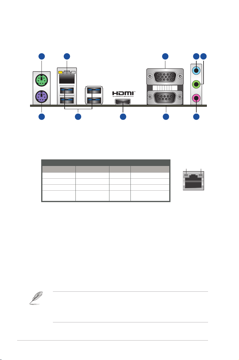
2.6.1 Rear panel connectors
2
6 7
3 1
8
9 10
5
4
1. PS/2 mouse port (green). This port is for a PS/2 mouse.
2. LAN (RJ-45) ports. These ports allow Gigabit connection to a Local Area
Network (LAN) through a network hub.
LAN port LED indications
LAN port
Speed
LED
Activity/Link LED Speed LED
Status Description Status Description
Off No link OFF 10Mbps connection
Orange Linked ORANGE 100Mbps connection
Orange (Blinking) Data activity GREEN 1Gbps connection
Orange (Blinking
then steady)
Ready to wake
up from S5 mode
Activity Link
LED
3. Video Graphics Adapter (VGA) ports. These 15-pin ports are for VGA
monitors or other VGA-compatible devices.
4. Line In port (light blue). This port connects to the tape, CD, DVD player, or
other audio sources.
5. Line Out port (lime). This port connects to a headphone or a speaker. In
the 4, and 5.1 channel congurations, the function of this port becomes Front
Speaker Out.
6. PS/2 keyboard port (purple). This port is for a PS/2 keyboard.
7. USB 3.2 Gen 1 (up to 5Gbps) ports. These 9-pin Universal Serial Bus
(USB) ports are for USB 3.2 Gen 1 devices.
2-10
• USB 3.2 Gen 1 devices can only be used for data storage.
• We strongly recommend that you connect USB 3.2 Gen 1 devices to USB
3.2 Gen 1 ports for faster and better performance from your USB 3.2 Gen 1
devices.
J3455I-CM-A
 Loading...