


IMX8P-IM-A
User Manual

E16394
First Edition
November 2020
COPYRIGHT INFORMATION
No part of this manual, including the products and software described in it, may be reproduced,
transmitted, transcribed, stored in a retrieval system, or translated into any language in any form or by
any means, except documentation kept by the purchaser for backup purposes, without the express
written permission of ASUSTeK COMPUTER INC. (“ASUS”).
ASUS PROVIDES THIS MANUAL “AS IS” WITHOUT WARRANTY OF ANY KIND, EITHER EXPRESS
OR IMPLIED, INCLUDING BUT NOT LIMITED TO THE IMPLIED WARRANTIES OR CONDITIONS OF
MERCHANTABILITY OR FITNESS FOR A PARTICULAR PURPOSE. IN NO EVENT SHALL ASUS, ITS
DIRECTORS, OFFICERS, EMPLOYEES OR AGENTS BE LIABLE FOR ANY INDIRECT, SPECIAL, INCIDENTAL,
OR CONSEQUENTIAL DAMAGES (INCLUDING DAMAGES FOR LOSS OF PROFITS, LOSS OF BUSINESS,
LOSS OF USE OR DATA, INTERRUPTION OF BUSINESS AND THE LIKE), EVEN IF ASUS HAS BEEN ADVISED
OF THE POSSIBILITY OF SUCH DAMAGES ARISING FROM ANY DEFECT OR ERROR IN THIS MANUAL OR
PRODUCT.
Products and corporate names appearing in this manual may or may not be registered trademarks or
copyrights of their respective companies, and are used only for identication or explanation and to
the owners’ benet, without intent to infringe.
SPECIFICATIONS AND INFORMATION CONTAINED IN THIS MANUAL ARE FURNISHED FOR
INFORMATIONAL USE ONLY, AND ARE SUBJECT TO CHANGE AT ANY TIME WITHOUT NOTICE, AND
SHOULD NOT BE CONSTRUED AS A COMMITMENT BY ASUS. ASUS ASSUMES NO RESPONSIBILITY OR
LIABILITY FOR ANY ERRORS OR INACCURACIES THAT MAY APPEAR IN THIS MANUAL, INCLUDING THE
PRODUCTS AND SOFTWARE DESCRIBED IN IT.
Copyright © 2020 ASUSTeK COMPUTER INC. All Rights Reserved.
LIMITATION OF LIABILITY
Circumstances may arise where because of a default on ASUS’ part or other liability, you are entitled to
recover damages from ASUS. In each such instance, regardless of the basis on which you are entitled
to claim damages from ASUS, ASUS is liable for no more than damages for bodily injury (including
death) and damage to real property and tangible personal property; or any other actual and direct
damages resulted from omission or failure of performing legal duties under this Warranty Statement,
up to the listed contract price of each product.
ASUS will only be responsible for or indemnify you for loss, damages or claims based in contract, tort
or infringement under this Warranty Statement.
This limit also applies to ASUS’ suppliers and its reseller. It is the maximum for which ASUS, its
suppliers, and your reseller are collectively responsible.
UNDER NO CIRCUMSTANCES IS ASUS LIABLE FOR ANY OF THE FOLLOWING: (1) THIRD-PARTY
CLAIMS AGAINST YOU FOR DAMAGES; (2) LOSS OF, OR DAMAGE TO, YOUR RECORDS OR DATA; OR (3)
SPECIAL, INCIDENTAL, OR INDIRECT DAMAGES OR FOR ANY ECONOMIC CONSEQUENTIAL DAMAGES
(INCLUDING LOST PROFITS OR SAVINGS), EVEN IF ASUS, ITS SUPPLIERS OR YOUR RESELLER IS
INFORMED OF THEIR POSSIBILITY.
SERVICE AND SUPPORT
Visit our multi-language web site at https://www.asus.com/support/

Contents
About this manual .............................................................................................................4
Conventions used in this manual ......................................................................................... 5
Typography .................................................................................................................................. 5
Package contents ..............................................................................................................6
Chapter 1: Specications Summary
IMX8P-IM-A Specications Summary .........................................................................8
Chapter 2: Product Introduction
2.1 Before you proceed ................................................................................................12
2.2 Motherboard layout ...............................................................................................13
2.3 Onboard button and switches ...........................................................................15
2.4 Internal connectors ................................................................................................17
2.5 I/O connectors ..........................................................................................................27
Chapter 3: Upgrading your Single Board Computer
3.1 Installing an Micro SD card ..................................................................................30
3.2 Installing the wireless card ..................................................................................31
Appendix
Safety information .............................................................................................................34
Setting up your system ............................................................................................................ 34
Care during use ........................................................................................................................... 35
Regulatory notices ............................................................................................................36
ASUS contact information ..............................................................................................43
Single Board Computer
3

About this manual
This manual provides information about the hardware and software features
of your Single Board Computer, organized through the following chapters:
Chapter 1: Specications Summary
This chapter details the hardware and software features of your Single
Board Computer.
Chapter 2: Product Introduction
This chapter describes the features of the motherboard. It includes
description of the connectors, and I/O ports on the motherboard.
Chapter 3: Upgrading your Single Board Computer
This chapter provides you with information on how to upgrade your
Single Board Computer.
Appendix
This section includes notices and safety statements your Single Board
Computer.
4
Single Board Computer

Conventions used in this manual
To highlight key information in this manual, some text are presented as
follows:
IMPORTANT! This message contains vital information that must be
followed to complete a task.
NOTE: This message contains additional information and tips that can
help complete tasks.
WARNING! This message contains important information that must be
followed to keep you safe while performing certain tasks and prevent
damage to your Single Board Computer's data and components.
Typography
Bold text Indicates a menu or an item to select.
Italic
This indicates sections that you can refer to in this manual.
Single Board Computer
5
Package contents
Your Single Board Computer package contains the following items:
IMX8P-IM-A
NOTE:
• Some bundled accessories may vary with dierent models. For
details on these accessories, refer to their respective user manuals.
• The device illustration is for reference only. Actual product
specications may vary with models.
• If the device or its components fail or malfunction during normal
and proper use within the warranty period, bring the warranty
card to the ASUS Service Center for replacement of the defective
components.
6
Single Board Computer

1
Specications Summary
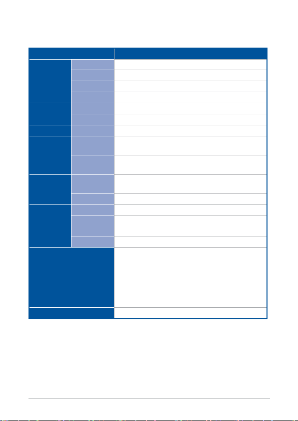
IMX8P-IM-A Specications Summary
IMX8P-IM-A
CPU NXP® i.MX 8 M ARM Cortex-A53 core
Processor
Memory
Storage
Graphics
Expansion
slot
Ethernet
Front I/O
Rear I/O
Max. Speed
L2 Cache
Chipset
Technology LPDDR4
Max.
eMMC 1 x 16GB onboard eMMC
HDMI™
MIPI DSI
M.2
Others
Speed 10/100/1000Mbps
Controller
Connector
1.3 GHz
1MB
Integrated
4GB, on board memory
1 x HMDI™ supports HDMI with max. resolution 3840
x 2160 @ 60 Hz
1 x MIPI DSI supports MIPI DSI (2 lane) with max.
resolution 1920 x 1080 @ 60 Hz
1 x M.2 2230 E Key for BT/WiFi module
(cooperate with Google EdgeTPU Module)
1 x Micro-SD Card slot
1 x Realtek® RTL8211
1 x Intel® I211-AT
2 x RJ-45
1 x HDMI™
2 x USB 3.2 Gen 1 Type-A ports
1 x USB 3.2 Gen 1 Type-C® OTG port
2 x Ethernet ports
1 x Power button
1 x Reset button
1 x DC-in jack
(continued on the next page)
8
Single Board Computer
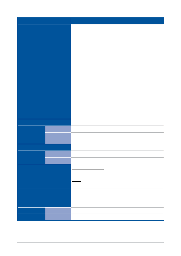
Internal Connector
Watchdog Timer (H/W)
Security
Module
TPM TPM 2.0 power by Nuvoton NCPT 750 (Optional)
Crypto
Module
Manageability
Power
Power Type DC power input
Voltage
Operating System
Environment
Dimension
Certication
Form Factor 100mm x 72mm x 21mm
Safety CE, FCC
IMX8P-IM-A
1 x 40-pin GPIO header:
- up to 6 x GPIO pins
- up to 2 x I2C bus pins
- up to 1 x UART pins
- up to 2 x PWM pins
- up to 1 x PCM/I2S pins
- 2 x 5V power pins
- 2 x 3.3V power pins
- 8 x ground pins
1 x Micro-SD card slot
1 x 14-1 pin TPM header
1 x MIPI DSI supports MIPI DSI (2 lane) with max.1920
x 1080 @ 60 Hz
2 x MIPI CSI support two MIPI-CSI camera inputs
(4-lane each)
1 x 5-1 pin I
2
C header
Yes
Cloud security power by Microchip ATECC608A / NXP
SE050 (Optional)
WOL
12-24V DC input
Microsoft Windows
Windows® 10 IoT Core
Linux
Linux Yocto
Operating Temperature: -20~60° C
Non-Operating Temperature: -40~85° C
Relative Humidity: 10%~95%
NOTE: Specications are subject to change without notice.
Single Board Computer
9

10
Single Board Computer

Product Introduction
Chapter 2: Product Introduction
2

2.1 Before you proceed
Take note of the following precautions before you install motherboard
components or change any motherboard settings.
NOTE: The diagrams in this chapter are for reference only. The
motherboard layout may vary with models.
IMPORTANT! Components shown in this section may require
additional purchase. Refer to Package contents section for more
information about the contents of your Single Board Computer
package.
WARNING!
• Unplug the power cord from the wall socket before touching any
component.
• Before handling components, use a grounded wrist strap or touch
a safely grounded object or a metal object, such as the power
supply case, to avoid damaging them due to static electricity.
• Hold components by the edges to avoid touching the ICs on them.
• Whenever you uninstall any component, place it on a grounded
antistatic pad or in the bag that came with the component.
• Before you install or remove any component, ensure that the
power cord is detached from the power supply. Failure to do so
may cause severe damage to the motherboard, peripherals, or
components.
12
Single Board Computer
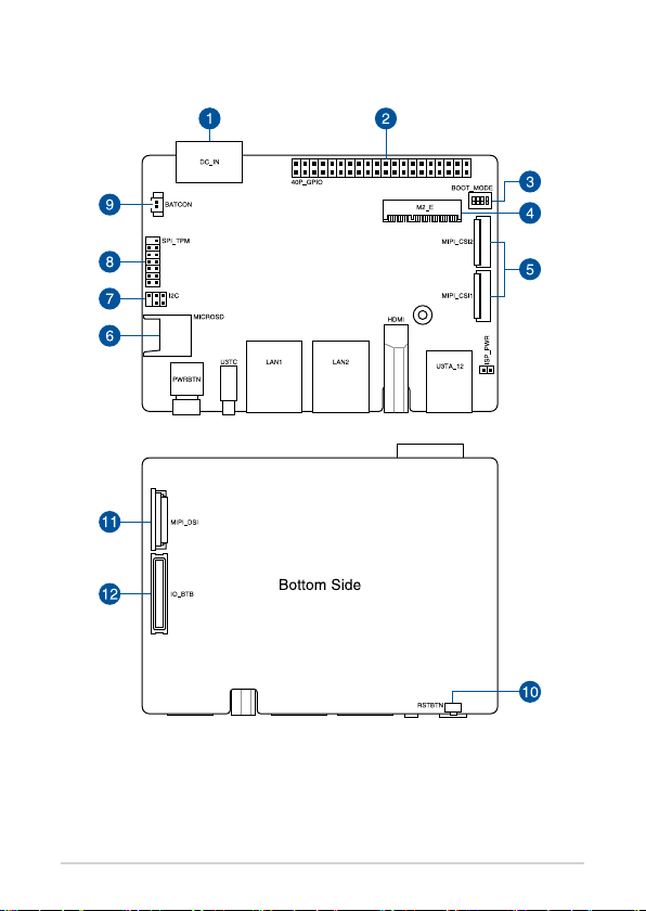
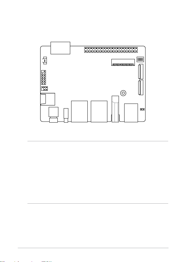
2.2 Motherboard layout
Single Board Computer
13
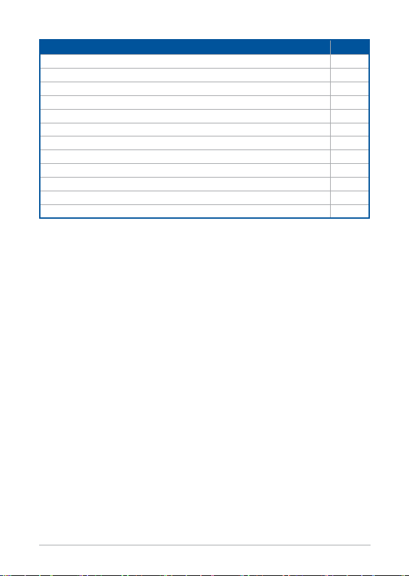
Layout contents Page
1. DC-in Power connector 19
2. GPIO header 20
3. Boot Mode switch 17
4. M.2 Wi-Fi slot 20
5. MIPI CSI connector 21
6. Micro SD card slot 22
7. I2C header 22
8. SPI TPM header 23
9. RTC Battery connector 23
10. Reset button 18
11. MIPI DSI connector 24
12. IO Board-to-Board connector 25
14
Single Board Computer
 Loading...