

Asus H110A-IM-A User’s Manual

H110A-IM-A
Industrial Motherboard

E17614
Revised Edition v2
November 2020
Copyright © 2020 ASUSTeK COMPUTER INC. All Rights Reserved.
No part of this manual, including the products and software described in it, may be reproduced,
transmitted, transcribed, stored in a retrieval system, or translated into any language in any form or by any
means, except documentation kept by the purchaser for backup purposes, without the express written
permission of ASUSTeK COMPUTER INC. (“ASUS”).
Product warranty or service will not be extended if: (1) the product is repaired, modied or altered, unless
such repair, modication of alteration is authorized in writing by ASUS; or (2) the serial number of the
product is defaced or missing.
ASUS PROVIDES THIS MANUAL “AS IS” WITHOUT WARRANTY OF ANY KIND, EITHER EXPRESS
OR IMPLIED, INCLUDING BUT NOT LIMITED TO THE IMPLIED WARRANTIES OR CONDITIONS OF
MERCHANTABILITY OR FITNESS FOR A PARTICULAR PURPOSE. IN NO EVENT SHALL ASUS, ITS
DIRECTORS, OFFICERS, EMPLOYEES OR AGENTS BE LIABLE FOR ANY INDIRECT, SPECIAL,
INCIDENTAL, OR CONSEQUENTIAL DAMAGES (INCLUDING DAMAGES FOR LOSS OF PROFITS,
LOSS OF BUSINESS, LOSS OF USE OR DATA, INTERRUPTION OF BUSINESS AND THE LIKE),
EVEN IF ASUS HAS BEEN ADVISED OF THE POSSIBILITY OF SUCH DAMAGES ARISING FROM ANY
DEFECT OR ERROR IN THIS MANUAL OR PRODUCT.
SPECIFICATIONS AND INFORMATION CONTAINED IN THIS MANUAL ARE FURNISHED FOR
INFORMATIONAL USE ONLY, AND ARE SUBJECT TO CHANGE AT ANY TIME WITHOUT NOTICE,
AND SHOULD NOT BE CONSTRUED AS A COMMITMENT BY ASUS. ASUS ASSUMES NO
RESPONSIBILITY OR LIABILITY FOR ANY ERRORS OR INACCURACIES THAT MAY APPEAR IN THIS
MANUAL, INCLUDING THE PRODUCTS AND SOFTWARE DESCRIBED IN IT.
Products and corporate names appearing in this manual may or may not be registered trademarks or
copyrights of their respective companies, and are used only for identication or explanation and to the
owners’ benet, without intent to infringe.
ii

Contents
Chapter 1 Product overview
1.1 Package contents......................................................................... 1-1
1.2 Features ........................................................................................ 1-1
1.3 Specifications ............................................................................... 1-2
Chapter 2 Motherboard information
2.1 Before you proceed ..................................................................... 2-1
2.2 Motherboard layout ...................................................................... 2-2
2.3 Central Processing Unit (CPU) ................................................... 2-4
2.3.1 Installing the CPU ........................................................... 2-5
2.3.2 CPU heatsink and fan assembly installation ................... 2-7
2.4 System memory ........................................................................... 2-9
2.5 Jumpers ...................................................................................... 2-11
2.6 Connectors ................................................................................. 2-14
2.6.1 Rear panel connectors .................................................. 2-14
2.6.2 Internal connectors ....................................................... 2-16
Chapter 3 BIOS setup
3.1 BIOS setup program .................................................................... 3-1
3.1.1 BIOS menu screen .......................................................... 3-2
3.2 Main menu .................................................................................... 3-2
3.2.1 System Date [Day MM/DD/YYYY] .................................. 3-2
3.2.2 System Time [HH:MM:SS] .............................................. 3-2
3.3 Advanced menu ........................................................................... 3-3
3.3.1 PCH-FW Conguration ................................................... 3-3
3.3.2 Trusted Computing ......................................................... 3-3
3.3.3 CPU Conguration .......................................................... 3-3
3.3.4 Graphics Conguration ................................................... 3-4
3.3.5 PCI Express Conguration .............................................. 3-5
3.3.6 CSM Conguration .......................................................... 3-6
3.3.7 Super IO Conguration ................................................... 3-6
3.3.8 Serial Console Conguration .......................................... 3-8
3.3.9 SATA Conguration ........................................................ 3-8
3.3.10 USB Conguration .......................................................... 3-8
3.3.11 Onboard Devices Conguration ...................................... 3-8
3.3.12 APM Conguration .......................................................... 3-9
iii

3.3.13 EzFlash ......................................................................... 3-10
3.3.14 Watchdog Timer ............................................................ 3-10
3.3.15 Network Stack Conguration ........................................ 3-10
3.3.16 Miscellaneous ............................................................... 3-10
3.4 Hardware Monitor menu ............................................................ 3-11
3.5 Security menu ............................................................................ 3-11
3.6 Boot menu .................................................................................. 3-13
Boot Conguration ....................................................................... 3-13
FIXED BOOT ORDER Priorities ................................................. 3-14
3.7 Exit menu .................................................................................... 3-15
Save Changes & Exit ................................................................... 3-15
Discard Changes & Exit ............................................................... 3-15
Save Changes & Reset ................................................................ 3-15
Discard Changes & Reset ............................................................ 3-15
Save changes .............................................................................. 3-15
Discard changes .......................................................................... 3-15
Restore Defaults .......................................................................... 3-15
Save as User Defaults ................................................................. 3-15
Restore User Defaults .................................................................. 3-15
Appendix
Notices .......................................................................................................A-1
ASUS contact information .......................................................................A-5
iv
Chapter 1
Product overview
1.1 Package contents
Check your industrial motherboard package for the following items.
1 x ASUS H110A-IM-A Industrial Motherboard
1 x SATA 6.0 Gb/s cable
1 x M.2 screw package
1 x ASUS I/O Shield
NOTE: If any of the above items is damaged or missing, contact your
distributor or sales representative immediately.
1.2 Features
• Intel® socket 1151 for 7th/6th Gen Intel® Core™ i7/ i5/ i3, Pentium®, and
Celeron® Processors
• Two Dual Channel DDR4 2400/2133MHz Non-ECC U-DIMMs up to 32GB
• 3 x SATA 6.0 Gb/s, 4 x USB 3.2 Gen 1, 6 x USB 2.0, 8 COM ports
• 2 x PCIe x16 slots, 1 x M.2 Socket 3 with Key M, 2242/2260/2280 (SATA
mode)
• Multi-display: 1 x VGA, 1 x HDMI (colay with DisplayPort)
Chapter 1: General information
1-1
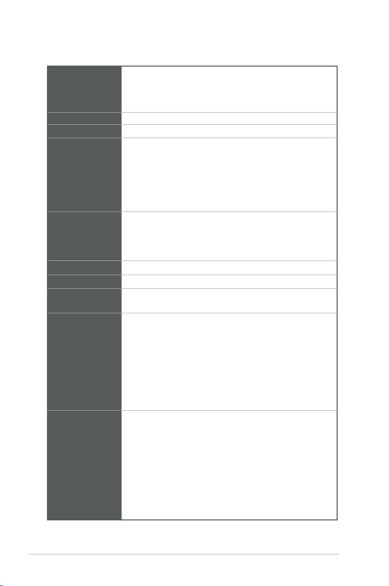
1.3 Specifications
CPU
Chipset
Memory
Graphics
Expansion slots
Storage
LAN
Audio
Rear I/O ports
Internal I/O
connectors
Intel® socket 1151 for 7th / 6th Gen Intel® Core™ i7/ i5/ i3,
®
Pentium
, and Celeron® Processors
Supports Intel® 14nm CPU
Supports up to 65W
Intel® H110 Chipset
2 x U-DIMM, max.32GB, DDR4 2400/2133 MHz SDRAM
Integrated graphics processor - Intel® HD Graphics support
Multi-VGA output support: VGA/HDMI ports
- Supports VGA output with a maximum resolution of 1920 x
1200 @ 60Hz
- Supports HDMI output with a maximum resolution of 4096 x
2160 @ 30 Hz (co-lay with optional DisplayPort 4096 x 2304
@ 60Hz)
1 x PCIe 3.0/2.0 x16 slot (x16 mode)
1 x PCIe 2.0 x16 slot (x4 mode, x4 pin)
5 x PCI slots
1 x M.2 Socket 3 with M key, type 2242/2260/2280 (SATA mode)
3 x SATA Gen 3.0, up to 6.0 Gb/s ports
Dual Intel® Lan: 1 x Intel® i219V, 1 x Intel® I211AT
Realtek ALC887-VD2 High Denition Audio
Line-Out, Line-In, Mic in
1 x VGA port
1 x HDMI port (colay with optional DisplayPort)
4 x USB 3.2 Gen 1 ports
2 x LAN (RJ45) ports
2 x COM ports (RS232/422/485)
1 x P/S2 keyboard port
1 x P/S2 mouse port
3 x Audio jacks
6 x COM headers (RS232)
2 x USB 2.0 headers support additional 4 USB 2.0 ports
2 x USB 2.0 connectors
1 x CPU Fan header (PWM mode)
1 x Chassis Fan header (PWM mode)
1 x Chassis intrusion header
1 x Front Panel Audio header (AAFP)
1 x System Panel header
1 x Clear CMOS header
(continued on the next page)
1-2
H110A-IM-A
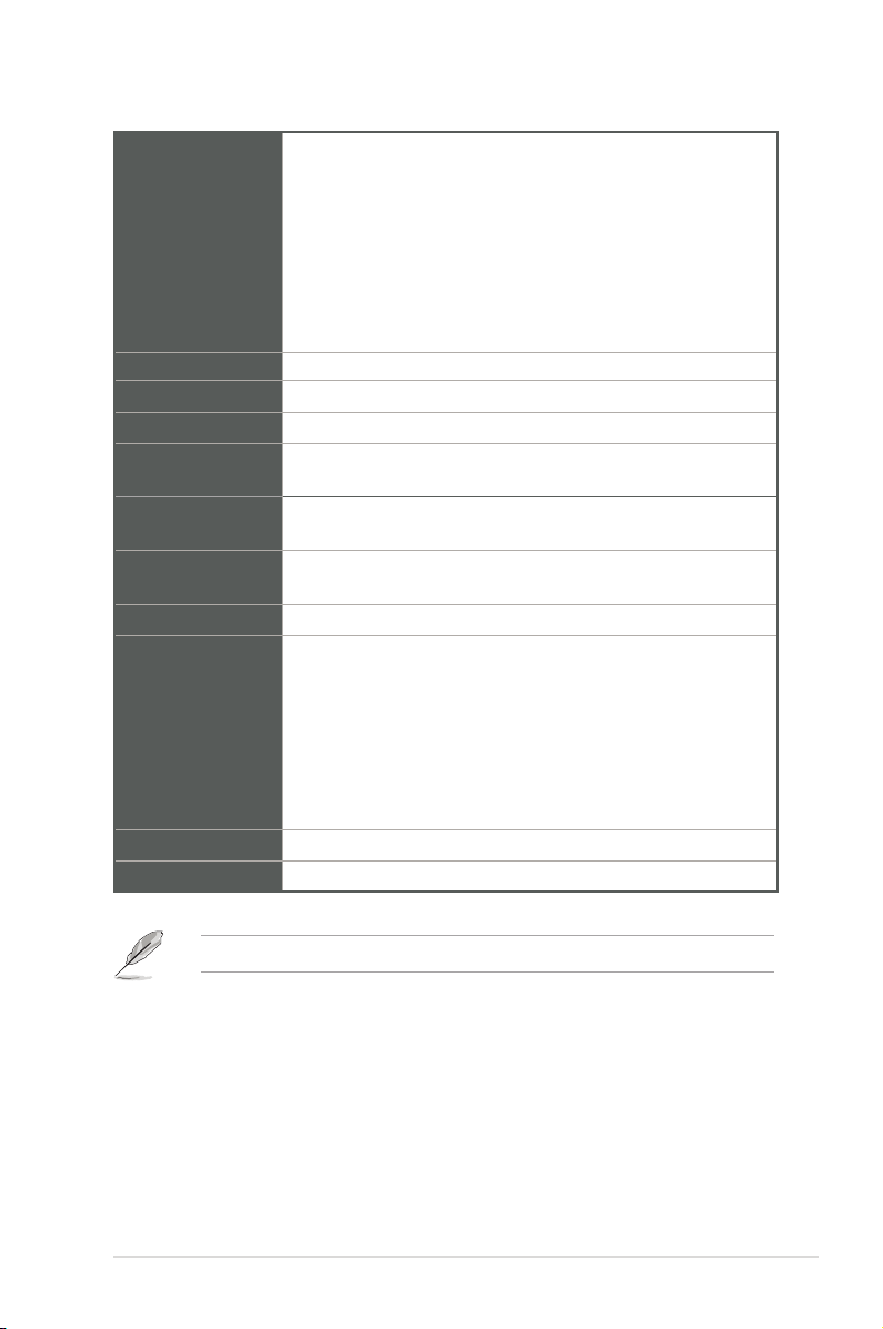
Internal I/O
connectors
GPIO
Manageability
Watch dog timer
Power
requirement
Operation
Temperature
Non-Operation
Temperature
Relative Humidity
OS support
Certification
Form Factor
1 x Speaker header
1 x LPC Debug header
1 x I2C header
1 x LPT header
1 x GPIO header (8-bit)
1 x AT/ATX mode selection jumper
1 x 24-pin ATX power connector
1 x 4-pin ATX power connector
1 x 8-bit GPIO header
WfM 2.0, DMI 2.0, WOL by PME
Yes
AT/ATX mode
0~60°C
-40~85°C
0%~85%
Windows® 7 (32/64bit )
Windows® 10 (64bit )
Windows® 10 IoT Enterprise
Ubuntu
RedHat Enterprise
Fedora Workstation
OpenSUSE
CE, FCC
ATX Form Factor, 12”x 9.6” (30.5cm x 24.4cm)
NOTE: Specications are subject to change without notice.
Chapter 1: General information
1-3

1-4
H110A-IM-A
Chapter 2
Motherboard information
2.1 Before you proceed
Take note of the following precautions before you install motherboard components
or change any motherboard settings.
CAUTION!
• Unplug the power cord from the wall socket before touching any
component.
• Before handling components, use a grounded wrist strap or touch a safely
grounded object or a metal object, such as the power supply case, to avoid
damaging them due to static electricity.
• Hold components by the edges to avoid touching the ICs on them.
• Whenever you uninstall any component, place it on a grounded antistatic
pad or in the bag that came with the component.
• Before you install or remove any component, always remove the AC power
by unplugging the power cord from the power outlet. Failure to do so may
cause severe damage to the motherboard, peripherals, or components.
Chapter 2: Motherboard information
2-1
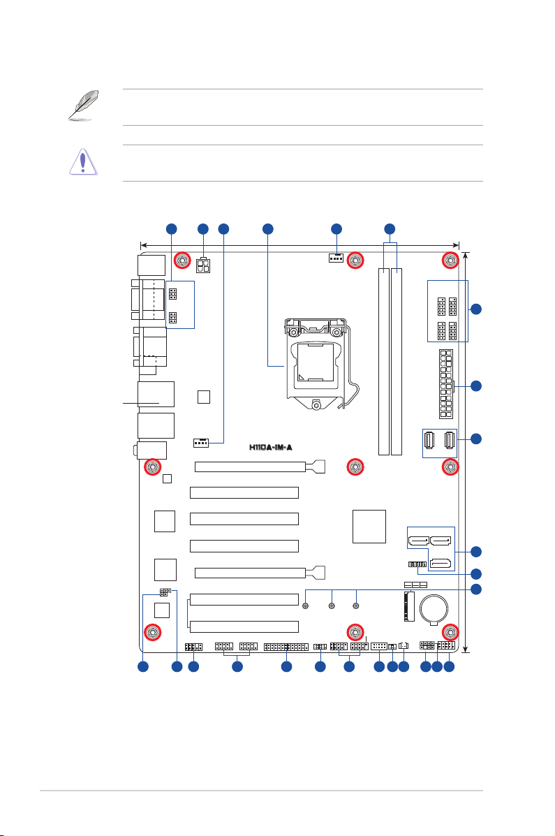
2.2 Motherboard layout
NOTE: Place nine screws into the holes indicated by circles to secure the
motherboard to the chassis.
CAUTION! Do not overtighten the screws! Doing so can damage the
motherboard.
Place this side
towards the rear
of the chassis
1 432 53
KBMS
COM2
VGA
HDMI
LAN2_U32G1_34
LAN1_U32G1_12
AUDIO
AT_ATX_SEL
COM1
ASM
1085
Super
WDT_EN
ALC
887
Intel
I219V
I/O
COM2_SEL
COM1_SEL
®
ATX12V
I211AT
CHA_FAN
AAFP
®
Intel
PCIEX16_1
PCI_1
PCI_2
PCI_3
PCIEX16_2
PCI_4
PCI_5
COM3 COM4
6192021 167
24.4cm(9.6in)
LGA1151
2280 2260 2242
LPT
LPC_DEBUG
1718
CPU_FAN
USB78
DDR4 DIMM_A1* (64bit, 288-pin module)
DDR4 DIMM_B1* (64bit,288-pin module)
USB9 USB10
®
Intel
H110
USB56
GPIO_CON
M.2(SOCKET3)
CLRTC
I2C
SATA6G_1 SATA6G_2
TPM
M.2(SOCKET3)
PCIE SATA IRST
X V X
SPEAKER
CHASSIS
SATA6G_3
BATTERY
COM5
COM7
EATXPWR
F_PANEL
1113 1215 14
COM6
COM8
1
6
2
7
30.5cm(12in)
8
9
10
2-2
H110A-IM-A
Connectors/Jumpers/Slots Page
1. COM RING/+5V/+12V selection (COM1/2_SEL) 2-12
2. ATX power connectors (24-pin EATXPWR, 4-pin ATX12V) 2-16
3. CPU and chassis fan headers (4-pin CPU_FAN, 4-pin CHA_FAN) 2-16
4. Intel® LGA1151 CPU socket 2-4
5. DDR4 U-DIMM slots 2-9
6. COM Port headers (10-1 pin COM3 - COM8) 2-17
7. USB 2.0 headers / connectors (10-1pin USB56, USB78 / USB9, USB10) 2-17
8. SATA 6.0 Gb/s ports (7-pin SATA6G_1-3) 2-18
9. TPM header (14-1 pin TPM) 2-18
10. M.2 slot (SOCKET 3) 2-19
11. System Panel header (10-1 pin F_PANEL) 2-20
12. Speaker header (4-1 pin SPEAKER) 2-21
13. Chassis Intrusion header (4-1 pin CHASSIS) 2-12
14. Clear RTC RAM (2-pin CLRTC) 2-11
15. I2C header (6-1 pin I2C) 2-21
16. General purpose input/output header (GPIO_CON) 2-22
17. LPC Debug header (10-1 LPC_DEBUG) 2-22
18. LPT header (26-1 pin LPT) 2-23
19. Front Panel Audio header (10-1 pin AAFP) 2-23
20. AT/ATX mode selection (3-pin AT_ATX_SEL) 2-13
21. WDT Enbale jumper (2-pin WDT_EN) 2-13
Chapter 2: Motherboard information
2-3
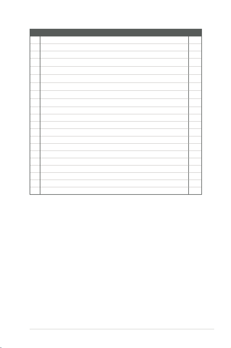
2.3 Central Processing Unit (CPU)
The motherboard comes with a surface mount LGA1151 socket designed for the
Intel® 7th/6th Generation Core™ i7 / Core™ i5 / Core™ i3, Pentium®, and Celeron®
Processors.
LGA1151
IMPORTANT: Unplug all power cables before installing the CPU.
CAUTION!
• Upon purchase of the motherboard, ensure that the PnP cap is on
the socket and the socket contacts are not bent. Contact your retailer
immediately if the PnP cap is missing, or if you see any damage to the
PnP cap/socket contacts/motherboard components. The manufacturer will
shoulder the cost of repair only if the damage is shipment/transit-related.
• Keep the cap after installing the motherboard. The manufacturer will
process Return Merchandise Authorization (RMA) requests only if the
motherboard comes with the cap on the LGA1151 socket.
• The product warranty does not cover damage to the socket contacts
resulting from incorrect CPU installation/removal, or misplacement/loss/
incorrect removal of the PnP cap.
2-4
H110A-IM-A
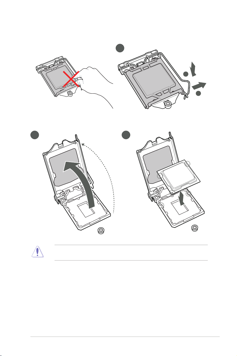
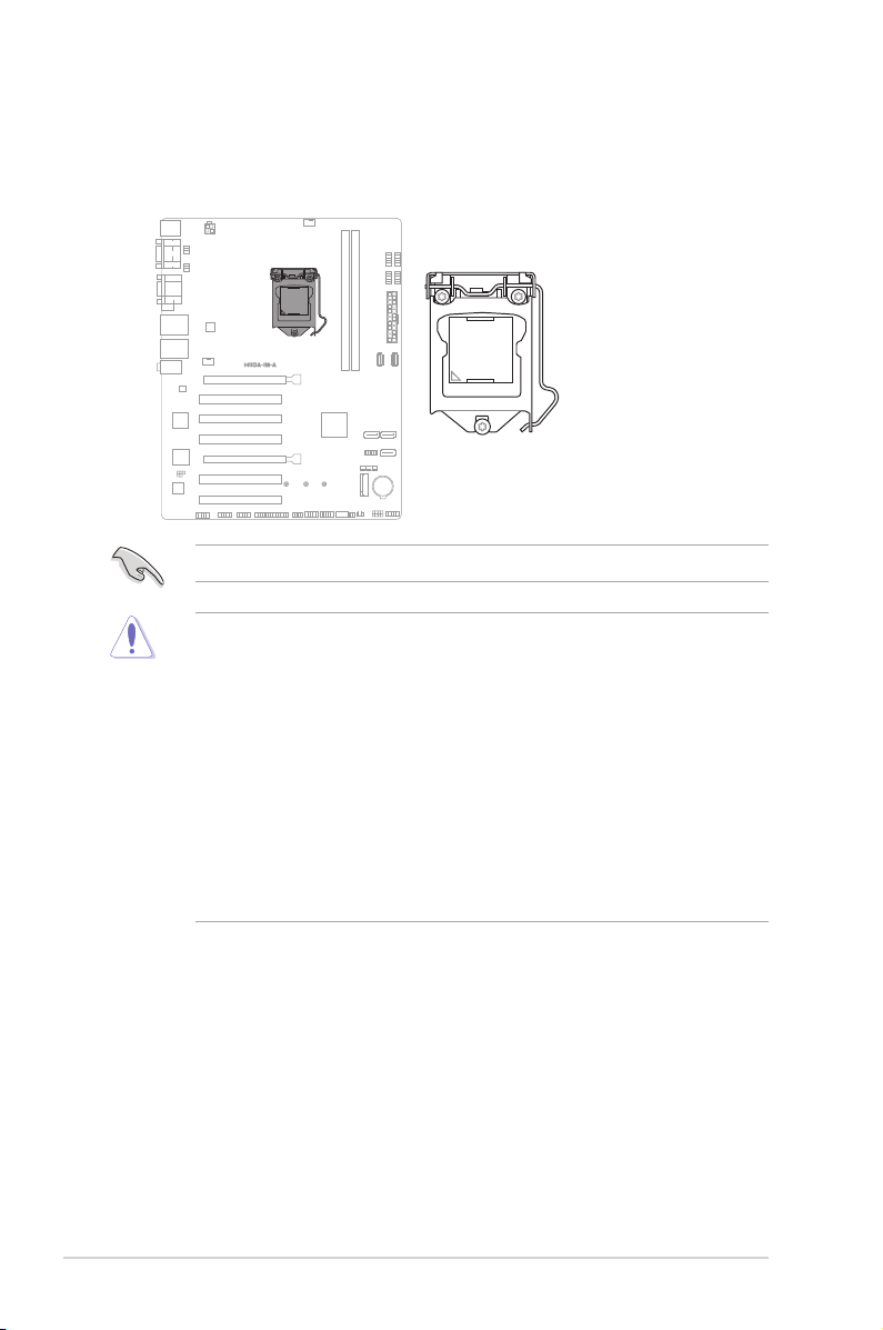
2.3.1 Installing the CPU
2 3
1
A
B
CAUTION! LGA1156 CPU is not compatible with the LGA1151 socket. DO
NOT install an LGA1156 CPU on the LGA1151 socket.
Chapter 2: Motherboard information
2-5
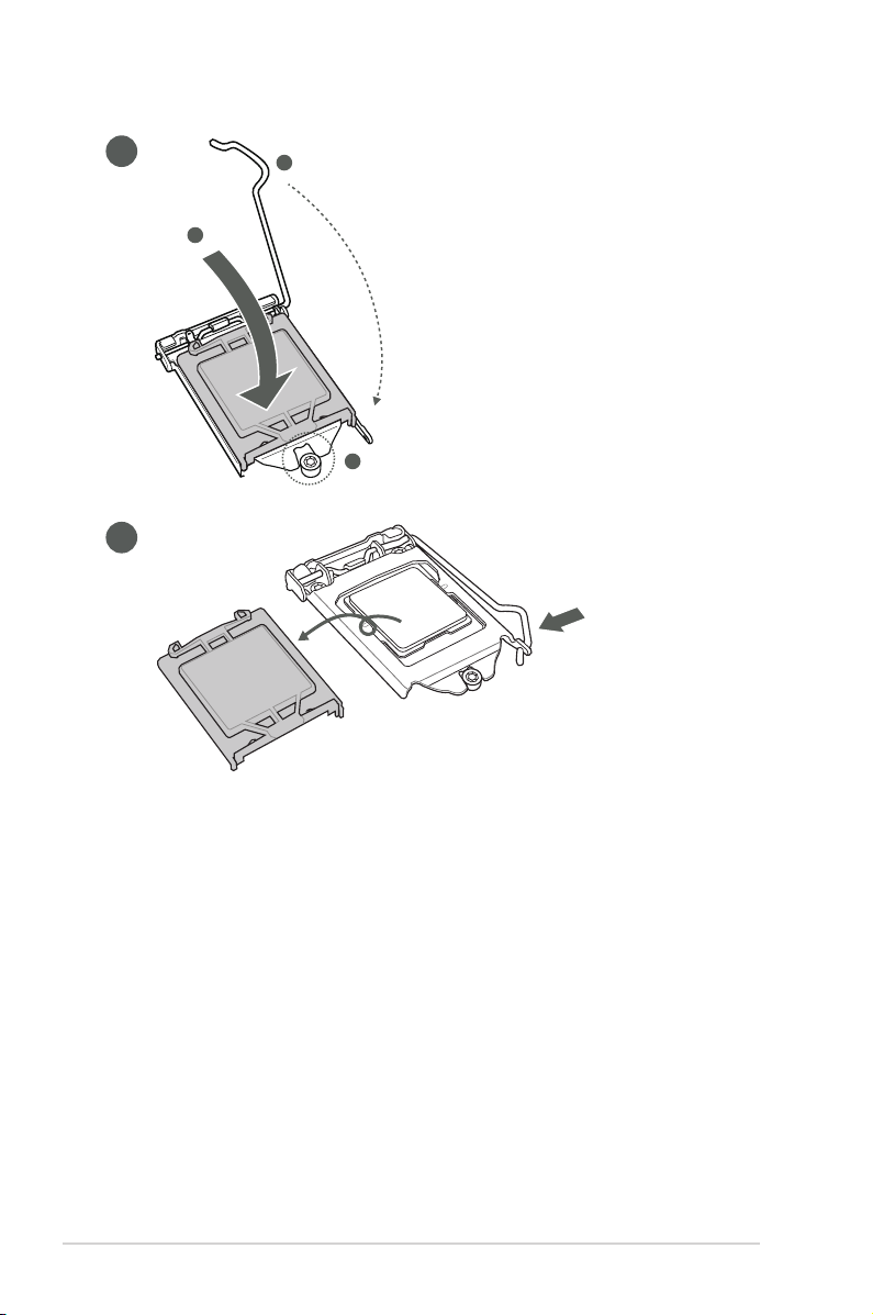
4
A
C
B
5
2-6
H110A-IM-A
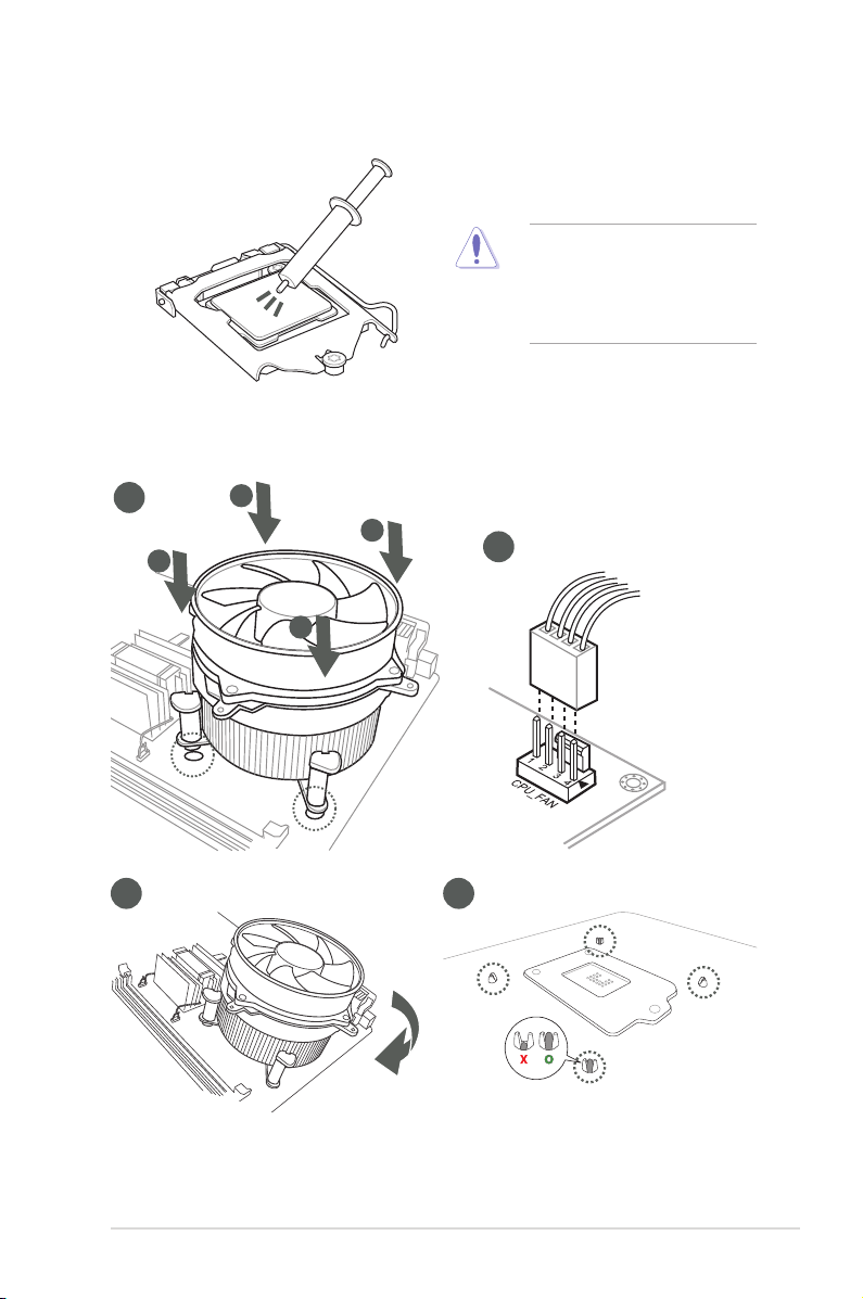
2.3.2 CPU heatsink and fan assembly installation
CAUTION! Apply the Thermal
Interface Material to the CPU
heatsink and CPU before you
install the heatsink and fan if
necessary.
To install the CPU heatsink and fan assembly
1
A
B
B
A
3 4
2
Chapter 2: Motherboard information
2-7
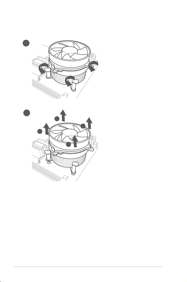
To uninstall the CPU heatsink and fan assembly
1
2
A
B
B
A
2-8
H110A-IM-A
 Loading...