

Page 1

G-SURF365
Motherboard
Page 2

E3497
First Edition
November 2007
Copyright © 2007 ASUSTeK COMPUTER INC. All Rights Reserved.
No part of this manual, including the products and software described in it, may be reproduced,
transmitted, transcribed, stored in a retrieval system, or translated into any language in any form or by any
means, except documentation kept by the purchaser for backup purposes, without the express written
permission of ASUSTeK COMPUTER INC. (“ASUS”).
Product warranty or service will not be extended if: (1) the product is repaired, modied or altered, unless
such repair, modication of alteration is authorized in writing by ASUS; or (2) the serial number of the
product is defaced or missing.
ASUS PROVIDES THIS MANUAL “AS IS” WITHOUT WARRANTY OF ANY KIND, EITHER EXPRESS
OR IMPLIED, INCLUDING BUT NOT LIMITED TO THE IMPLIED WARRANTIES OR CONDITIONS OF
MERCHANTABILITY OR FITNESS FOR A PARTICULAR PURPOSE. IN NO EVENT SHALL ASUS, ITS
DIRECTORS, OFFICERS, EMPLOYEES OR AGENTS BE LIABLE FOR ANY INDIRECT, SPECIAL,
INCIDENTAL, OR CONSEQUENTIAL DAMAGES (INCLUDING DAMAGES FOR LOSS OF PROFITS,
LOSS OF BUSINESS, LOSS OF USE OR DATA, INTERRUPTION OF BUSINESS AND THE LIKE),
EVEN IF ASUS HAS BEEN ADVISED OF THE POSSIBILITY OF SUCH DAMAGES ARISING FROM ANY
DEFECT OR ERROR IN THIS MANUAL OR PRODUCT.
SPECIFICATIONS AND INFORMATION CONTAINED IN THIS MANUAL ARE FURNISHED FOR
INFORMATIONAL USE ONLY, AND ARE SUBJECT TO CHANGE AT ANY TIME WITHOUT NOTICE,
AND SHOULD NOT BE CONSTRUED AS A COMMITMENT BY ASUS. ASUS ASSUMES NO
RESPONSIBILITY OR LIABILITY FOR ANY ERRORS OR INACCURACIES THAT MAY APPEAR IN THIS
MANUAL, INCLUDING THE PRODUCTS AND SOFTWARE DESCRIBED IN IT.
Products and corporate names appearing in this manual may or may not be registered trademarks or
copyrights of their respective companies, and are used only for identication or explanation and to the
owners’ benet, without intent to infringe.
ii
Page 3

Contents
Contents ...................................................................................................... iii
Notices ......................................................................................................... vi
Safety information
About this guide
G-SURF365 specications summary ......................................................... x
Chapter 1: Product introduction
1.1 Welcome! ...................................................................................... 1-2
1.2 Package contents
1.3 Special features
1.3.1 Product highlights ...........................................................
1.3.2 Innovative ASUS features ...............................................
1.4 Before you proceed
1.5 Motherboard overview
1.5.1 Motherboard layout .........................................................
1.5.2 Placement direction ........................................................
1.5.3 Screw holes ....................................................................
1.6 Central Processing Unit (CPU)
1.6.1 Installing the CPU .........................................................
1.6.2 Installing the heatsink and fan ......................................
1.7 System memory
1.7.1 Overview .......................................................................
1.7.2 Memory congurations ..................................................
1.7.3 Installing a DIMM ..........................................................
1.7.4 Removing a DIMM ........................................................
1.8 Expansion slots
1.8.1 Installing an expansion card .........................................
1.8.2 Conguring an expansion card .....................................
1.8.3 PCI slots ........................................................................
1.8.4 PCI Express x16 slot .....................................................
1.9 Jumpers
1.10 Connectors
1.10.1 Rear panel connectors ..................................................
1.10.2 Internal connectors .......................................................
1.11 G-Guardian
1.11.1 Installing the Memory Lock ...........................................
..................................................................................... vii
....................................................................................... viii
......................................................................... 1-2
............................................................................ 1-3
..................................................................... 1-7
................................................................. 1-8
................................................. 1-10
......................................................................... 1-14
.......................................................................... 1-20
...................................................................................... 1-23
................................................................................. 1-25
................................................................................. 1-36
1-3
1-5
1-8
1-9
1-9
1-10
1-12
1-14
1-14
1-19
1-19
1-20
1-20
1-22
1-22
1-25
1-27
1-36
iii
Page 4

Contents
1.11.2 Installing the Back I/O Lock .......................................... 1-37
Chapter 2: BIOS setup
2.1 Managing and updating your BIOS ............................................ 2-2
2.1.1 Creating a bootable oppy disk .......................................
2.1.2 ASUS EZ Flash 2 utility ...................................................
2.1.3 AFUDOS utility ................................................................
2.1.4 ASUS CrashFree BIOS 3 utility ......................................
2.1.5 ASUS Update utility ........................................................
2.2 BIOS setup program
2.2.1 BIOS menu screen ........................................................
2.2.2 Menu bar .......................................................................
2.2.3 Navigation keys .............................................................
2.2.4 Menu items ...................................................................
2.2.5 Sub-menu items ............................................................
2.2.6 Conguration elds .......................................................
2.2.7 Pop-up window .............................................................
2.2.8 Scroll bar .......................................................................
2.2.9 General help .................................................................
2.3 Main menu
2.3.1 System Time .................................................................
2.3.2 System Date .................................................................
2.3.3 Legacy Diskette A .........................................................
2.3.4. Language ......................................................................
2.3.5 IDE Conguration ..........................................................
2.3.6 Primary IDE Master/Slave .............................................
2.3.7 SATA1/2 ........................................................................
2.3.8 System Information .......................................................
2.4 Extreme Tweaker menu
2.4.1 CPU Level Up ...............................................................
2.4.2 Ai Overclocking .............................................................
2.4.3 Processor Frequency Multiplier ....................................
2.4.4 K8(CPU) to SB Freq Auto .............................................
2.4.5 K8(CPU) to SB Frequency ............................................
2.4.6 K8(CPU) to SB LinkWidth .............................................
2.4.7 Memory Conguration ...................................................
.................................................................................. 2-15
.................................................................. 2-12
............................................................. 2-21
2-3
2-4
2-5
2-7
2-9
2-13
2-13
2-13
2-14
2-14
2-14
2-14
2-14
2-14
2-15
2-15
2-15
2-15
2-16
2-17
2-18
2-20
2-21
2-21
2-22
2-22
2-23
2-23
2-23
iv
Page 5

Contents
2.4.8 ECC Conguration ........................................................ 2-25
2.4.9 Vcore Voltage ................................................................
2.4.10 Vcore Voltage Offset .....................................................
2.4.11 Chipset Voltage .............................................................
2.4.12 Memory Voltage ............................................................
2.5 Advanced menu
2.5.1 CPU Conguration ........................................................
2.5.2 Chipset ..........................................................................
2.5.3 Onboard Devices Conguration ....................................
2.5.4 PCI PnP ........................................................................
2.5.5 USB Conguration ........................................................
2.6 Power menu
2.6.1 Suspend Mode ..............................................................
2.6.2 ACPI
2.6.3 ACPI APIC Support .......................................................
2.6.4 APM Conguration ........................................................
2.6.5 Hardware Monitor .........................................................
2.7 Boot menu
2.7.1 Boot Device Priority ......................................................
2.7.2 Boot Settings Conguration ..........................................
2.7.3 Security .........................................................................
2.8 Tools menu
2.8.1 ASUS EZ Flash 2 ..........................................................
2.8.2 ASUS O.C. Prole .........................................................
2.9 Exit menu
.................................................................................... 2-43
2-26
2-26
2-26
2-26
......................................................................... 2-27
2-27
2-28
2-28
2-30
2-31
................................................................................ 2-33
2-33
Version Features ................................................. 2-33
2-33
2-34
2-35
.................................................................................. 2-37
2-37
2-38
2-39
................................................................................. 2-41
2-41
2-42
Chapter 3: Software support
3.1 Installing an operating system ................................................... 3-2
3.2 Support CD information
3.2.1 Running the support CD .................................................
3.2.2 Drivers menu ...................................................................
3.2.3 Utilities menu ..................................................................
3.2.4 Make Disk menu .............................................................
3.2.5 Manual menu ..................................................................
3.2.6 ASUS Contact information ..............................................
3.2.7 Other information ............................................................
.............................................................. 3-2
3-2
3-3
3-4
3-5
3-6
3-6
3-7
v
Page 6

Notices
Federal Communications Commission Statement
This device complies with Part 15 of the FCC Rules. Operation is subject to the
following two conditions:
•
This device may not cause harmful interference, and
•
This device must accept any interference received including interference that
may cause undesired operation.
This equipment has been tested and found to comply with the limits for a
Class B digital device, pursuant to Part 15 of the FCC Rules. These limits are
designed to provide reasonable protection against harmful interference in a
residential installation. This equipment generates, uses and can radiate radio
frequency energy and, if not installed and used in accordance with manufacturer’s
instructions, may cause harmful interference to radio communications. However,
there is no guarantee that interference will not occur in a particular installation. If
this equipment does cause harmful interference to radio or television reception,
which can be determined by turning the equipment off and on, the user is
encouraged to try to correct the interference by one or more of the following
measures:
•
Reorient or relocate the receiving antenna.
•
Increase the separation between the equipment and receiver.
•
Connect the equipment to an outlet on a circuit different from that to which the
receiver is connected.
•
Consult the dealer or an experienced radio/TV technician for help.
The use of shielded cables for connection of the monitor to the graphics card is
required to assure compliance with FCC regulations. Changes or modications
to this unit not expressly approved by the party responsible for compliance
could void the user’s authority to operate this equipment.
Canadian Department of Communications Statement
This digital apparatus does not exceed the Class B limits for radio noise emissions
from digital apparatus set out in the Radio Interference Regulations of the
Canadian Department of Communications.
This class B digital apparatus complies with Canadian
ICES-003.
vi
Page 7

Safety information
Electrical safety
•
To prevent electrical shock hazard, disconnect the power cable from the
electrical outlet before relocating the system.
•
When adding or removing devices to or from the system, ensure that the power
cables for the devices are unplugged before the signal cables are connected. If
possible, disconnect all power cables from the existing system before you add
a device.
•
Before connecting or removing signal cables from the motherboard, ensure
that all power cables are unplugged.
•
Seek professional assistance before using an adapter or extension cord.
These devices could interrupt the grounding circuit.
•
Make sure that your power supply is set to the correct voltage in your area. If
you are not sure about the voltage of the electrical outlet you are using, contact
your local power company.
•
If the power supply is broken, do not try to x it by yourself. Contact a qualied
service technician or your retailer.
Operation safety
•
Before installing the motherboard and adding devices on it, carefully read all
the manuals that came with the package.
•
Before using the product, make sure all cables are correctly connected and the
power cables are not damaged. If you detect any damage, contact your dealer
immediately.
•
To avoid short circuits, keep paper clips, screws, and staples away from
connectors, slots, sockets and circuitry.
•
Avoid dust, humidity, and temperature extremes. Do not place the product in
any area where it may become wet.
•
Place the product on a stable surface.
•
If you encounter technical problems with the product, contact a qualied
service technician or your retailer.
The symbol of the crossed out wheeled bin indicates that the product (electrical
and electronic equipment, Mercury-containing button cell battery) should not
be placed in municipal waste. Please check local regulations for disposal of
electronic products.
vii
Page 8

About this guide
This user guide contains the information you need when installing and conguring
the motherboard.
How this guide is organized
This manual contains the following parts:
• Chapter 1: Product introduction
This chapter describes the features of the motherboard and the new
technology it supports. This chapter also lists the hardware setup procedures
that you have to perform when installing system components. It includes
description of the jumpers and connectors on the motherboard.
• Chapter 2: BIOS setup
This chapter tells how to change system settings through the BIOS Setup
menus. Detailed descriptions of the BIOS parameters are also provided.
• Chapter 3: Software support
This chapter describes the contents of the support CD/DVD that comes with
the motherboard package.
Where to nd more information
Refer to the following sources for additional information and for product and
software updates.
1. ASUS websites
The ASUS website provides updated information on ASUS hardware and
software products. Refer to the ASUS contact information.
2. Optional documentation
Your product package may include optional documentation, such as warranty
yers, that may have been added by your dealer. These documents are not
part of the standard package.
viii
Page 9

Conventions used in this guide
To make sure that you perform certain tasks properly, take note of the following
symbols used throughout this manual.
DANGER/WARNING: Information to prevent injury to yourself
when trying to complete a task.
CAUTION: Information to prevent damage to the components
when trying to complete a task.
IMPORTANT: Instructions that you MUST follow to complete a
task.
NOTE: Tips and additional information to help you complete a
task.
Typography
Bold text Indicates a menu or an item to select.
Italics
Used to emphasize a word or a phrase.
<Key> Keys enclosed in the less-than and greater-than sign
means that you must press the enclosed key.
Example: <Enter> means that you must press the
Enter or Return key.
<Key1+Key2+Key3> If you must press two or more keys simultaneously, the
key names are linked with a plus sign (+).
Example: <Ctrl+Alt+D>
Command Means that you must type the command exactly as
shown, then supply the required item or value enclosed
in brackets.
Example: At the DOS prompt, type the command line:
format A:/S
ix
Page 10

G-SURF365 specications summary
CPU Support AMD® Socket AM2 Athlon™ 64 FX / Athlon™ 64
Chipset NVIDIA nForce 630a
System bus 2000 / 1600 MT/s
Memory Dual-channel memory architecture 2 x 240-pin DIMM
Expansion slots 1 x PCI Express™ x16 slot
Storage - 1 x Ultra DMA 133/100 interface for two PATA devices
High Denition Audio Realtek® ALC662 High Denition Audio 6-channel
LAN NVidia nForce built-in Gigabit MAC with external Marvell
USB Supports up to 6 USB 2.0 / 1.1 ports (2 ports at mid-
Manageability WfM2.0, DMI2.0, PXE, WOR by Ring, WOL / WOR by
Special features ASUS CPU Level Up
X2 / Athlon™ 64 / Sempron processors
AMD64 architecture enables simultaneous 32-bit and
64-bit computing
Supports AMD Cool ‘n’ Quiet™ Technology
sockets support up to 4 GB of ECC / Non-ECC
unbufferred 800 / 667 / 533 MHz DDR2 memory
modules
2 x PCI slots
- 2 x Serial ATA 3 Gb/s hard disk drives supporting RAID
0, 1, and JBOD conguration
CODEC
Supports S/PDIF out interface and Jack-detection
88E1116 PHY
board; 4 ports at back panel)
PME
ASUS MyLogo 3™
ASUS CrashFree BIOS 3
ASUS EZ Flash 2
ASUS Q-Fan
(continued on the next page)
x
Page 11

G-SURF365 specications summary
BIOS features 8 Mb Flash ROM, AMI BIOS, PnP, DMI2.0, WfM2.0,
Rear panel I/O 1 x PS/2 mouse port
Internal I/O connectors 1 x USB 2.0 connectors for 2 additional USB 2.0 ports
Support CD contents Drivers
Form Factor ATX Form Factor, 12 in. x 9.6 in. (30.5cm x 24.5cm)
*Specications are subject to change without notice.
SM BIOS 2.4
1 x PS/2 keyboard port
1 x G-Guardian port
1 x LAN (RJ-45) port
4 x USB 2.0/1.1 ports
6-channel audio ports
1 x Floppy disk drive connector
1 x IDE connector for two devices
1 x High Denition front panel audio connector
1 x CD audio-in connector
1 x S/PDIF Out connector
1 x LPT connector
1 x COM connector
1 x CPU fan connector
1 x Chassis fan connector
1 x Chassis intrusion connector
24-pin EATX power connector
4-pin x ATX 12V power connector
1 x System panel connector
ASUS PC Probe II
ASUS Live Update Utility
Anti-virus software (OEM version)
xi
Page 12

xii
Page 13

This chapter describes the motherboard
features and the new technologies it
supports.
introduction
Product
1
Page 14

1.1 Welcome!
Thank you for buying an ASUS® G-SURF365 motherboard!
The motherboard delivers a host of new features and latest technologies, making it
another standout in the long line of ASUS quality motherboards!
Before you start installing the motherboard, and hardware devices on it, check the
items in your package with the list below.
1.2 Package contents
Check your motherboard package for the following items.
Motherboard ASUS G-SURF365 motherboard
Cables 1 x Serial ATA signal cable
1 x Serial ATA power cable
1 x Ultra DMA 133/100 cable
1 x Floppy disk drive cable
Accessories 1 x G-Guardian (1 set of memory lock and
1 back I/O lock)
1 x I/O shield
Application CD ASUS motherboard support CD
ASUS SUPERB Software
Documentation User guide
If any of the above items is damaged or missing, contact your retailer.
1-2 Chapter 1: Product introduction
Page 15

1.3 Special features
1.3.1 Product highlights
Republic of Gamers
The Republic of Gamers consists only the best of the best. We offer the best
hardware engineering, the fastest performance, the most innovating ideas, and we
welcome the best gamers to join in. In the Republic of Gamers, mercy rules are
only for the weak, and bragging rights means everything. We believe in making
statements and we excel in competitions. If your character matches our trait, then
join the elite club, make your presence felt, in the Republic of Gamers.
Latest processor technology
The motherboard supports AMD socket AM2 single-core Athlon 64/ Sempron and
dual-core Athlon 64 X2/Athlon 64 FX processors with 2MB/1MB/512KB L2 cache,
which is based on 64-bit architecture. It features 2000/1600 MT/s HyperTransport
Bus, dual-channel un-buffered DDR2 800 memory support and AMD Cool ‘n’ Quiet
Technology. See page 1-10 for details.
AMD Cool ‘n’ Quiet Technology
The motherboard supports the AMD Cool ‘n’ Quiet Technology, which monitors
system operation and automatically adjusts CPU voltage and frequency for a cool
and quiet operating environment. See page 2-28 for details.
Dual-Core CPU
Enjoy the extraordinary CPU power from the latest dual-core CPU. The advanced
processing technology contains two physical CPU cores with individually dedicated
L2 cache to satisfy the rising demand for more powerful processing capability.
64-bit CPU support
64-bit computing, the next generation technology to replace current 32-bit
architecture, delivers advanced system performance, faster memory access and
increased productivity. This motherboard provides excellent compatibility and
exibility by supporting either 64-bit or 32-bit architecture.
NVIDIA® nForce™ 630a
The NVIDIA® nForce™ 630a MCP delivers NVIDIA® Gigabit LAN, and NVIDIA®
MediaShield storage management technology allowing easy RAID conguration
(RAID 0, RAID 1 and JBOD) for Serial ATA 3Gb/s.
ASUS G-SURF365 1-3
Page 16
Dual channel DDR2 800
DDR2 800 memory provides great performance for 3D graphics and other memory
demanding applications on next generation memory technology. See page 1-14 for
details.
PCI Express™ interface
The motherboard fully supports PCI Express, the latest I/O interconnect
technology that speeds up the PCI bus. PCI Express features point-to-point serial
interconnections between devices and allows higher clockspeeds by carrying data
in packets. This high speed interface is software compatible with existing PCI
specications. See page 1-22 for details.
Serial ATA 3Gb/s technology
The motherboard supports next-generation SATA hard drives based on the
new SATA 3Gb/s storage specication. It allows RAID 0, RAID 1 and JBOD
congurations for two SATA connectors. See page 1-29 or details.
Gigabit LAN technology
The on-board LAN controller is a highly integrated GbLAN controller. It is enhanced
with an ACPI management function to provide efcient power management for
advanced operating systems. See page 1-25 for details.
High Denition Audio
Enjoy high-quality sound system on your PC! The onboard 6-channel HD audio
(High Denition Audio, previously codenamed Azalia) CODEC enables high-quality
192KHz/24-bit audio output, jack-sensing feature, retasking functions technology
that automatically detects and identies what types of peripherals are plugged into
the audio I/O jacks and noties users of inappropriate connection, meaning there
will be no more confusion of Line-in, Line-out and Mic jacks. See pages 1-25 and
3-3 for details.
1-4 Chapter 1: Product introduction
Page 17
1.3.2 Innovative ASUS features
ASUS CPU Level Up
Ever wish that you could have a more expansive CPU? Upgrade your CPU at no
additional cost with ROG’s CPU Level Up! Simply choose a processor you want to
OC to, and the motherboard will do the rest for you. See the new CPU speed and
enjoy the performance instantly! Overclocking is never as easy as this. See page
2-21 for details.
ASUS G-Guardian
G-Guardian is the best protector of your memory modules and PC peripherals!
With G-Guardian assembled on your motherboard, you will never worry about
your keyboard, mouse, webcam, headset and memory modules being stolen. See
pages 1-36 to 1-39 for deails.
ASUS Q-Fan technology
ASUS Q-Fan technology intelligently adjusts CPU fan speeds according to system
loading to ensure quiet, cool and efcient operation. See page 2-36 for details.
ASUS CrashFree BIOS 3
This feature allows you to restore the original BIOS data from the support CD in case
when the BIOS codes and data are corrupted. This protection eliminates the need to
buy a replacement BIOS chip. See page 2-7 for details.
ASUS EZ Flash 2
EZ Flash 2 is a user-friendly BIOS update utility. Simply press the predened
hotkey to launch the utility and update the BIOS without entering the OS. Update
your BIOS easily without preparing a bootable diskette or using an OS-based ash
utility. See pages 2-4 and 2-41 for details.
C.P.R. (CPU Parameter Recall)
The C.P.R. feature of the motherboard BIOS allows automatic re-setting to the
BIOS default settings in case the system hangs due to overclocking. When the
system hangs due to overclocking, C.P.R. eliminates the need to open the system
chassis and clear the RTC data. Simply shut down and reboot the system, and the
BIOS automatically restores the CPU default setting for each parameter. See page
1-23 for details.
ASUS G-SURF365 1-5
Page 18

ASUS MyLogo 3™
This feature allows you to convert your favorite photo into a 256-color boot logo for
a more colorful and vivid image on your screen. See page 2-38 for details.
Green ASUS
The motherboard and its packaging comply with the European Union’s
Restriction on the use of Hazardous Substances (RoHS). This is in line with
the ASUS vision of creating environment-friendly and recyclable products and
packaging to safeguard consumers’ health while minimizing the impact on the
environment.
1-6 Chapter 1: Product introduction
Page 19
1.4 Before you proceed
G-SURF365
®
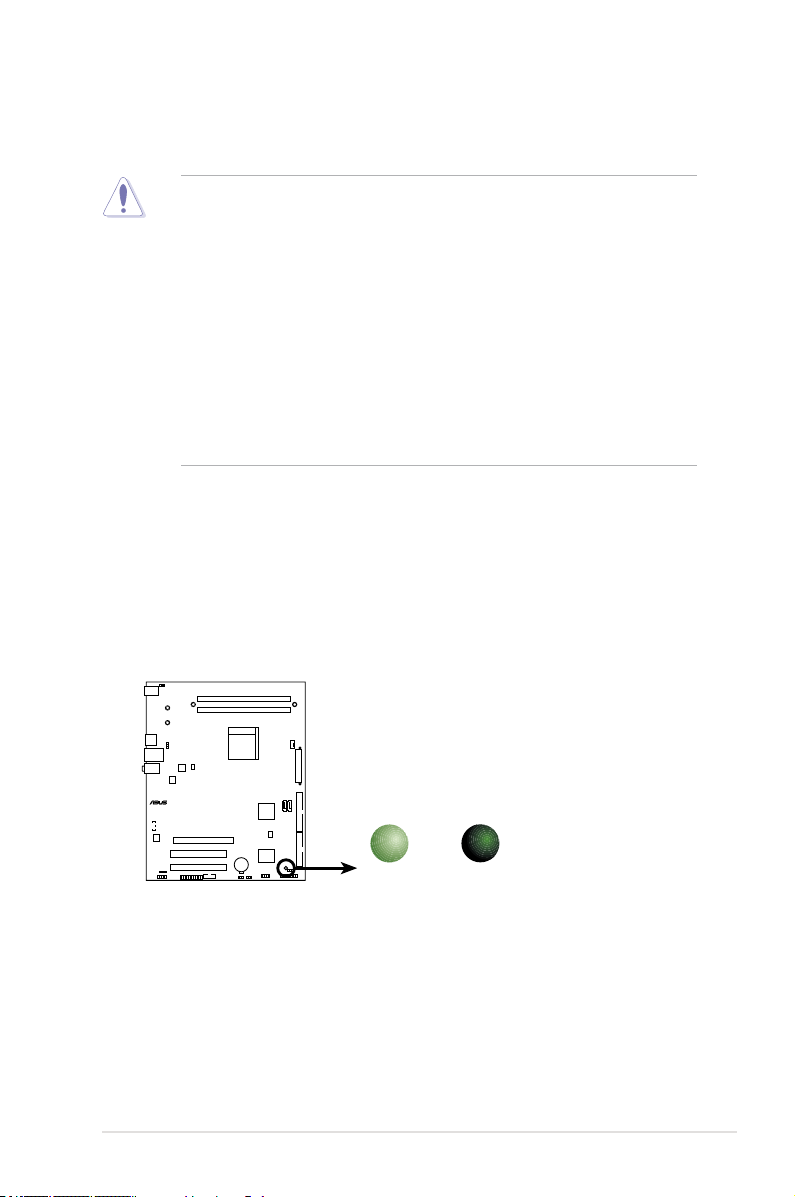
G-SURF365 Onboard LED
SB_PWR
ON
Standby
Power
OFF
Powered
Off
Take note of the following precautions before you install motherboard components
or change any motherboard settings.
• Unplug the power cord from the wall socket before touching any
component.
• Use a grounded wrist strap or touch a safely grounded object or a metal
object, such as the power supply case, before handling components to
avoid damaging them due to static electricity
• Hold components by the edges to avoid touching the ICs on them.
• Whenever you uninstall any component, place it on a grounded antistatic
pad or in the bag that came with the component.
• Before you install or remove any component, ensure that the ATX power
supply is switched off or the power cord is detached from the power
supply. Failure to do so may cause severe damage to the motherboard,
peripherals, and/or components.
Onboard LED
The motherboard comes with a standby power LED that lights up to indicate that
the system is ON, in sleep mode, or in soft-off mode. This is a reminder that you
should shut down the system and unplug the power cable before removing or
plugging in any motherboard component. The illustration below shows the location
of the onboard LED.
ASUS G-SURF365 1-7
Page 20
PANEL
G-SURF365
®
24.5cm (9.6in)
30.5cm (12.0in)
CPU_FAN
DDR2 DIMM_A1 (64 bit,240-pin module)
FLOPPY
Super
I/O
EATXPWR
CR2032 3V
Lithium Cell
CMOS Power
USB34
CHA_FAN
COM1
DDR2 DIMM_B1 (64 bit,240-pin module)
PCI1
PCIEX16_1
LAN1_USB12
CLRTC
SB_PWR
ATX12V
Socket AM2
USBPW1-4
KBPWR
PS/2KBMS
T: Mouse
B: Keyboard
PCI2
LPT
SPDIF_OUT
AAFP
USBPW1-4
CHASSIS
USB56
SATA1
NVIDIA
®
nForce630a
ALC662
BIOS
PRI_IDE
SATA2
Bottom:Mic In
Center:Line Out
Top:Line In
Marvell
88E1116
CD
NUT3
NUT4
NUT1 NUT2
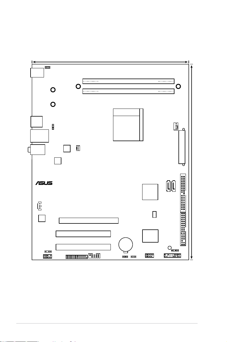
1.5 Motherboard overview
1.5.1 Motherboard layout
1-8 Chapter 1: Product introduction
Page 21

G-SURF365
®
1.5.2 Placement direction
When installing the motherboard, make sure that you place it into the chassis in
the correct orientation. The edge with external ports goes to the rear part of the
chassis as indicated in the image below.
1.5.3 Screw holes
Place nine (9) screws into the holes indicated by circles to secure the
motherboard to the chassis.
Do not overtighten the screws! Doing so can damage the motherboard.
Place this side towards
the rear of the chassis
ASUS G-SURF365 1-9
Page 22
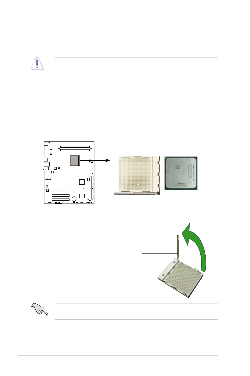
1.6 Central Processing Unit (CPU)
G-SURF365
®
G-SURF365 CPU Socket AM2
The motherboard comes with a 940-pin AM2 socket designed for the AMD
Athlon™ 64 FX / Athlon™ 64 X2 / Athlon™ 64 / Sempron™ processor.
The AM2 socket has a different pinout from the 940-pin socket designed for the
AMD Opteron™ processor. Make sure you use a CPU is designed for the AM2
socket. The CPU ts in only one correct orientation. DO NOT force the CPU into
the socket to prevent bending the connectors on the socket and damaging the
CPU!
1.6.1 Installing the CPU
To install a CPU.
1. Locate the CPU socket on the motherboard.
2. Unlock the socket by pressing the
lever sideways, then lift it up to a
90°-100° angle.
Socket lever
Make sure that the socket lever is lifted up to 90°-100° angle, otherwise the
CPU does not t in completely.
1-10 Chapter 1: Product introduction
Page 23
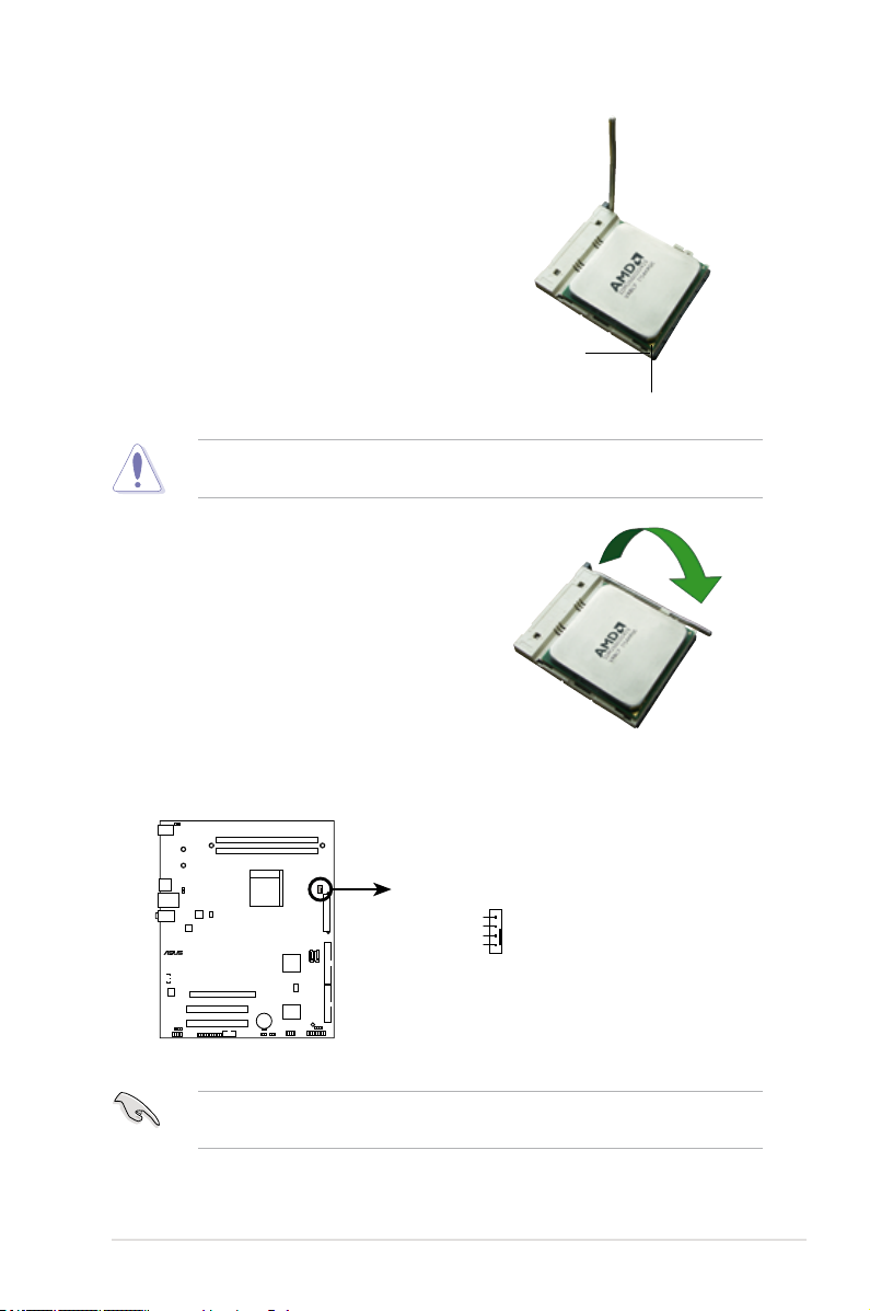
3. Position the CPU above the socket
G-SURF365
®
G-SURF365 CPU fan connector
CPU_FAN
GND
CPU FAN PWR
CPU FAN IN
CPU FAN PWM
such that the CPU corner with the
gold triangle matches the socket
corner with a small triangle.
4. Carefully insert the CPU into the
socket until it ts in place.
Small triangle
Gold triangle
The CPU ts only in one correct orientation. DO NOT force the CPU into the
socket to prevent bending the pins and damaging the CPU!
5. When the CPU is in place, push
down the socket lever to secure the
CPU. The lever clicks on the side
tab to indicate that it is locked.
6. Install a CPU heatsink and fan
following the instructions that came
with the heatsink package.
7. Connect the CPU fan cable to the CPU_FAN connector on the motherboard.
Do not forget to connect the CPU fan connector! Hardware monitoring errors
can occur if you fail to plug this connector.
ASUS G-SURF365 1-11
Page 24
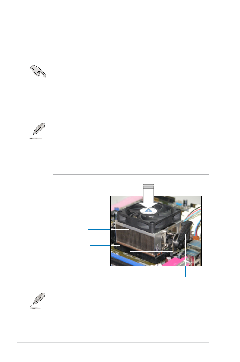
1.6.2 Installing the heatsink and fan
The AMD Athlon™ 64 FX / Athlon™ 64 X2 / Athlon™ 64 / Sempron™ processor
require a specially designed heatsink and fan assembly to ensure optimum thermal
condition and performance.
Make sure that you use only qualied heatsink and fan assembly.
Follow these steps to install the CPU heatsink and fan.
1. Place the heatsink on top of the installed CPU, making sure that the heatsink
ts properly on the retention module base.
• The retention module base is already installed on the motherboard
upon purchase.
• You do not have to remove the retention module base when
installing the CPU or installing other motherboard components.
• If you purchased a separate CPU heatsink and fan assembly, make
sure that a Thermal Interface Material is properly applied to the CPU
heatsink or CPU before you install the heatsink and fan assembly.
CPU Fan
CPU Heatsink
Retention Module Base
Retention bracket lockRetention bracket
Your boxed CPU heatsink and fan assembly should come with installation
instructions for the CPU, heatsink, and the retention mechanism. If the
instructions in this section do not match the CPU documentation, follow the
latter.
1-12 Chapter 1: Product introduction
Page 25
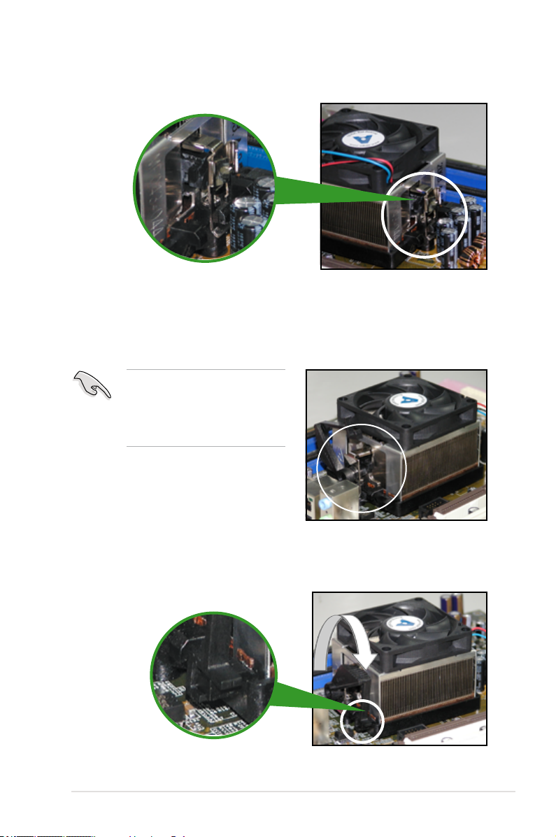
2. Attach one end of the retention bracket to the retention module base.
3. Align the other end of the retention bracket (near the retention bracket lock)
to the retention module base. A clicking sound denotes that the retention
bracket is in place.
Make sure that the fan and
heatsink assembly perfectly ts
the retention mechanism module
base; otherwise, you cannot snap
the retention bracket in place.
4. Push down the retention bracket lock on the retention mechanism to secure
the heatsink and fan to the module base.
ASUS G-SURF365 1-13
Page 26
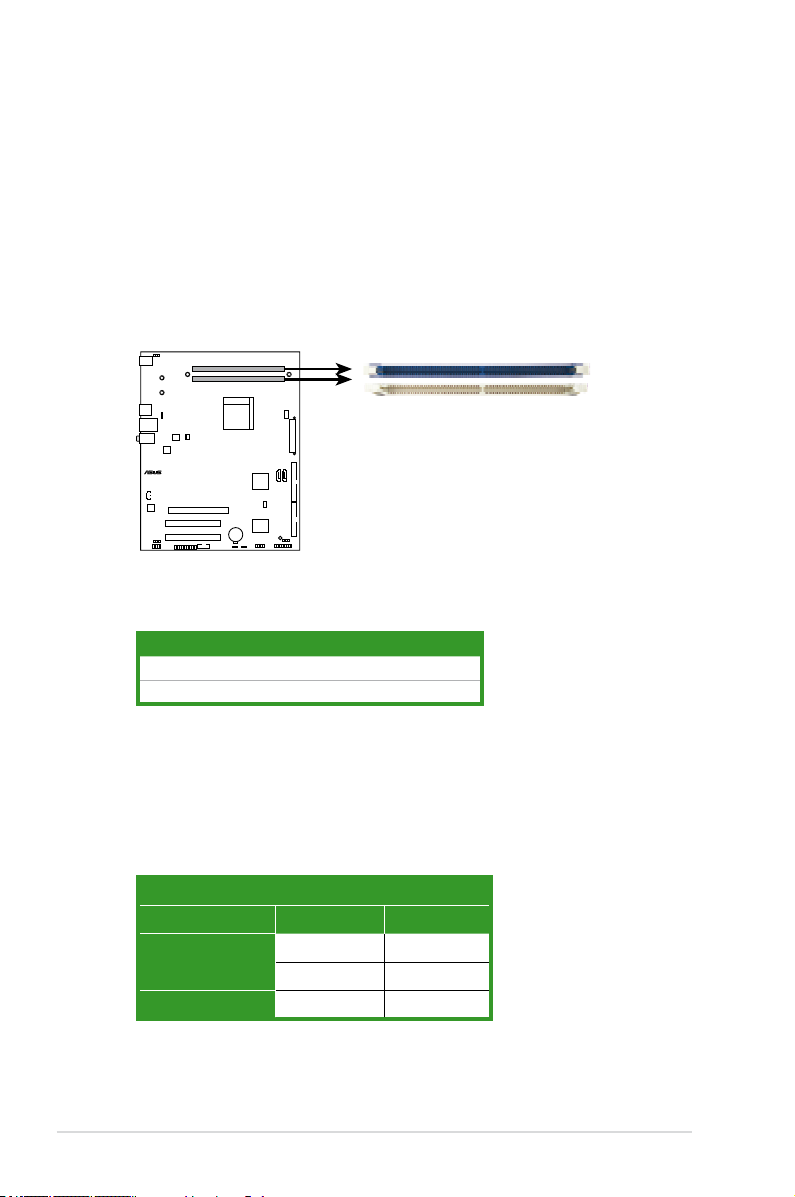
1.7 System memory
G-SURF365
®
G-SURF365 240-pin DDR2 DIMM sockets
DIMM_B1
DIMM_A1
1.7.1 Overview
The motherboard comes with two Double Data Rate 2 (DDR2) Dual Inline Memory
Modules (DIMM) sockets.
A DDR2 module has the same physical dimensions as a DDR DIMM but has a
240-pin footprint compared to the 184-pin DDR DIMM. DDR2 DIMMs are notched
differently to prevent installation on a DDR DIMM socket.
The gure illustrates the location of the DDR2 DIMM sockets:
Channel Sockets
Channel A DIMM_A1
Channel B DIMM_B1
1.7.2 Memory congurations
You may install 256 MB, 512 MB, 1 GB, and 2 GB unbuffered ECC/non-ECC
DDR2 DIMMs into the DIMM sockets.
Recommended memory congurations
Sockets
Mode DIMM_A1 DIMM_B1
Single-Channel
Dual-channel Populated Populated
1-14 Chapter 1: Product introduction
– Populated
Populated –
Page 27
Always use identical DDR2 DIMM pairs for dual channel mode. For optimum
compatibility, it is recommended that you obtain memory modules from the
same vendor. Visit the ASUS website (www.asus.com) for the latest Qualied
Vendors list.
Important notice on installing Windows® XP 32-bit version
If you install Windows® XP 32-bit version Operating System (OS), the limitation
of this OS version is that it may reserve a certain amount of memory space for
system devices. We recommend that you install less than 3 GB system memory
if you would like to work under Windows® XP 32-bit version OS. The excess
memory installation will not cause any usage problem, but it will not give users
the benet of manipulating this excess memory space.
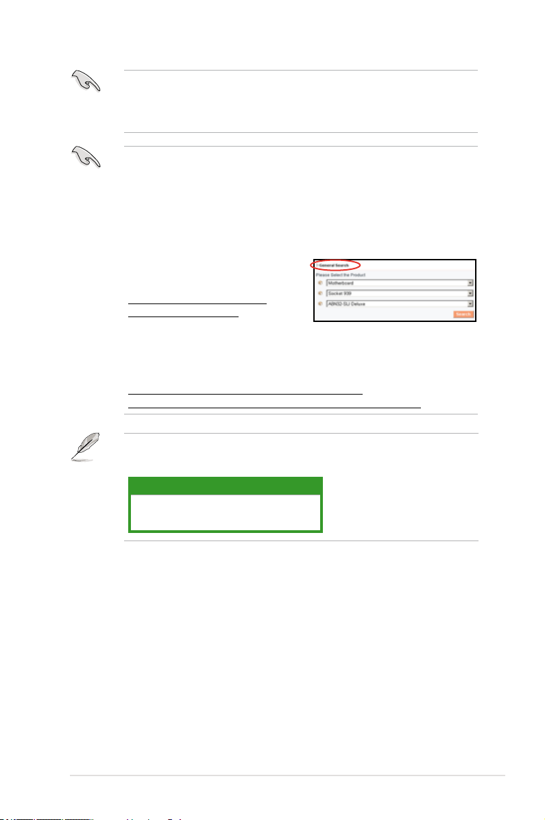
Visit the ASUS FAQ site for further
explanation:
http://support.asus.com/faq/faq.
aspx?SLanguage=en-us
Under General Search, make the
selections as shown, then click Search. Click the article titled “4GB memory
installed but less memory size detected.”
You also may check the URLs below for third party comments on this issue:
http://dlsvr01.asus.com/pub/ASUS/mb/4GB_Rev1.pdf
http://www.intel.com/support/motherboards/server/sb/cs-016594.htm
This motherboard can support 4 GB physical memory on the operating systems
listed below. You may install a maximum of 2 GB DIMMs on each slot.
64-bit
Windows® XP Professional x64 Edition
Windows® Vista x64 Edition
ASUS G-SURF365 1-15
Page 28

Qualied Vendors Lists (QVL) DDR2-800 MHz capability
Size Vendor Chip No. SS/DS Part No.
512MB KINGSTON K4T51083QC SS KVR800D2N5/512 * *
1024MB KINGSTON Heat-Sink Package DS KHX6400D2LL/1G * *
1024MB KINGSTON Heat-Sink Package SS KHX6400D2LLK2/1GN * *
1024MB KINGSTON V59C1512804QBF25 DS KVR800D2N5/1G * *
1024MB KINGSTON Heat-Sink Package SS KHX6400D2ULK2/1G * *
2048MB KINGSTON Heat-Sink Package DS KHX6400D2ULK2/2G * *
512MB Qimonda HYB18T512800BF25F SS HYS64T64000HU-25F-B * *
1024MB Qimonda HYB18T512800BF25F DS HYS64T128020HU-25F-B * *
512MB Hynix HY5PS12821CFP-S5 SS HYMP564U64CP8-S5 * *
1024MB Hynix HY5PS12821CFP-S5 DS HYMP512U64CP8-S5 * *
512MB MICRON D9GKX SS MT8HTF6464AY-80ED4 * *
1024MB MICRON D9GKX DS MT16HTF12864AY-80ED4 * *
512MB CORSAIR Heat-Sink Package SS CM2X512A-6400 * *
1024MB CORSAIR Heat-Sink Package DS CM2X1024-6400C4 * *
1024MB ELPIDA E1108AB-8E-E(ECC) SS EBE10EE8ABFA-8E-E * *
2048MB ELPIDA E1108AB-8E-E(ECC) DS EBE21EE8ABFA-8E-E * *
512MB Crucial Heat-Sink Package SS BL6464AA804.8FD * *
512MB Crucial Heat-Sink Package SS BL6464AA804.8FD3 * *
1024MB Crucial Heat-Sink Package DS BL12864AA804.16FD * *
1024MB Crucial Heat-Sink Package DS BL12864AL804.16FD3 * *
1024MB Crucial Heat-Sink Package DS BL12864AA804.16FD3 * *
512MB Apacer Heat-Sink Package DS AHU512E800C5K1C * *
1024MB Apacer Heat-Sink Package DS AHU01GE800C5K1C * *
512MB A-DATA AD29608A8A-25EG SS M2OAD6G3H3160G1E53 * *
1024MB A-DATA AD26908A8A-25EG DS M2OAD6G3I4170I1E58 * *
512MB KINGMAX KKA8FEIBF-HJK-25A SS KLDC28F-A8KI5 * *
1024MB KINGMAX KKA8FEIBF-HJK-25A DS KLDD48F-ABKI5 * *
512MB Transcend HY5PS12821CFP-S5 SS TS64MLQ64V8J * *
1024MB Transcend HY5PS12821CFP-S5 DS TS128MLQ64V8J * *
512MB Super Talent Heat-Sink Package SS T800UA12C4 * *
1024MB Super Talent Heat-Sink Package DS T800UB1GC4 * *
512MB NANYA NT5TU64M8BE-25C SS NT512T64U880BY-25C * *
1024MB NANYA NT5TU64M8BE-25C DS NT1GT64U8HB0BY-25C * *
1024MB NANYA NT5TU64M8CE-25D DS NT1GT64U8HCOBY-25D * *
512MB PSC A3R12E3HEF641B9A05 SS AL6E8E63B8E1K * *
1024MB PSC A3R12E3HEF641B9A05 DS AL7E8E63B-8E1K * *
256MB TwinMOS E2508AB-GE-E SS 8G-24IK2-EBT * *
1024MB Elixir N2TU51280BE-25C DS M2Y1G64TU8HB0B-25C * *
DIMM socket support (Optional)
A* B*
1-16 Chapter 1: Product introduction
Page 29

Qualied Vendors Lists (QVL) DDR2-667 MHz capability
Size Vendor Chip No.
512MB KINGSTON D6408TEBGGL3U SS KVR667D2N5/512 * *
256MB KINGSTON HYB18T256800AF3S SS KVR667D2N5/256 * *
256MB KINGSTON 6SBI2D9DCG SS KVR667D2N5/256 * *
2048MB KINGSTON E1108AB-6E-E DS KVR667D2N5/2G * *
512MB Qimonda HYB18T512800BF3S(ECC) SS HYS72T64000HU-3S-B * *
1024MB Qimonda HYB18T512800BF3S(ECC) DS HYS72T128020HU-3S-B * *
512MB Qimonda HYB18T512800BF3S SS HYS64T64000HU-3S-B * *
1024MB Qimonda HYB18T512800BF3S DS HYS64T128020HU-3S-B * *
512MB SAMSUNG K4T51163QE-ZCE6 DS M378T3354EZ3-CE6 * *
256MB SAMSUNG K4T51083QE SS M378T6553EZS-CE6 * *
1024MB SAMSUNG K4T51083QE DS M378T2953EZ3-CE6 * *
256MB Hynix HY5PS121621CFP-Y5 SS HYMP532U64CP6-Y5 * *
1024MB Hynix HY5PS12821CFP-Y5 DS HYMP512U64CP8-Y5 * *
256MB CORSAIR MIII00605 SS VS256MB667D2 * *
512MB CORSAIR 64M8CFEG SS VS512MB667D2 * *
1024MB CORSAIR 64M8CFEG DS VS1GB667D2 * *
256MB ELPIDA E2508AB-6E-E SS EBE25UC8ABFA-6E-E * *
512MB ELPIDA E5108AE-6E-E SS EBE51UD8AEFA-6E-E * *
512MB A-DATA AD29608A8A-3EG SS M2OAD5G3H3166I1C52 * *
1024MB A-DATA AD29608A8A-3EG DS M2OAD5G3I4176I1C52 * *
2048MB A-DATA NT5TU128M8BJ-3C DS M2ONY5H3J4170I1C5Z * *
512MB crucial Heat-Sink Package SS BL6464AA663.8FD * *
1024MB crucial Heat-Sink Package DS BL12864AA663.16FD * *
1024MB crucial Heat-Sink Package DS BL12864AL664.16FD * *
1024MB crucial Heat-Sink Package DS BL12864AA663.16FD2 * *
512MB Apacer AM4B5708GQJS7E0628F SS AU512E667C5KBGC * *
1024MB Apacer AM4B5708GQJS7E DS AU01GE667C5KBGC * *
512MB Transcend K4T51083QE SS TS64MLQ64V6J * *
1024MB Transcend K4T51083QE DS TS128MLQ64V6J * *
256MB Kingmax N2TU51216AG-3C SS KLCB68F-36KH5 * *
512MB Kingmax KKEA88B4LAUG-29DX SS KLCC28F-A8KB5 * *
1024MB Kingmax KKEA88B4LAUG-29DX DS KLCD48F-A8KB5 * *
512MB Super Talent Heat-Sink Package SS T6UA512C5 * *
1024MB Super Talent Heat-Sink Package DS T6UB1GC5 * *
2048MB NANYA NT5TU128M8BJ-3C DS NT2GT64U8HB0JY-3C * *
512MB NANYA NT5TU64M8BE-3C SS NT512T64U88B0BY-3C * *
512MB PSC A3R12E3GEF637BLC5N SS AL6E8E63B-6E1K * *
1024MB PSC A3R12E3GEF637BLC5N DS AL7E8E63B-6E1K * *
SS/
DS
Part No.
DIMM socket support (Optional)
A* B*
ASUS G-SURF365 1-17
Page 30

Qualied Vendors Lists (QVL) DDR2-667 MHz capability (continued)
Size Vendor Chip No.
512MB TwinMOS E5108AE-GE-E SS 8G-25JK5-EBT * *
512MB TwinMOS TMM6208G8M30C SS 8D-23JK5M2ETP * *
SS/
DS
Part No.
DIMM socket support (Optional)
A* B*
Qualied Vendors Lists (QVL) DDR2-533 MHz capability
Size Vendor Chip No.
512MB KINGSTON HYB18T512800AF37 SS KVR533D2N4/512 * *
1024MB KINGSTON D6408TPAGGL3U DS KVR533D2N4/1G * *
2048MB KINGSTON E1108AB-6E-E DS KVR533D2N4/2G * *
512MB Qimonda HYB18T512800BF37 SS HYS64T64000HU-3.7-B * *
1024MB Qimonda HYB18T512800BF37 DS HYS64T128020HU-3.7-B * *
256MB Hynix HY5PS121621CFP-C4 SS HYMP532U64CP6-C4 * *
1024MB Hynix HY5PS12821CFP-C4 DS HYMP512U64CP8-C4 * *
256MB CORSAIR 32M16CEDG SS VS256MB533D2 * *
512MB CORSAIR MI110052432M8CEC DS VS512MB533D2 * *
1024MB CORSAIR 64M8CEDG DS VS1GB533D2 * *
512MB ELPIDA E5108AB-5C-E(ECC) SS EBE51ED8ABFA-5C-E * *
512MB ELPIDA E5108AB-5C-E SS EBE51UD8ABFA-5C * *
512MB ELPIDA E5108AB-5C-E SS EBE51UD8ABFA-5C-E * *
1024MB ELPIDA E5108AB-5C-E DS EBE11UD8ABFA-5C-E * *
512MB KINGMAX E5108AE-5C-E SS KLBC28F-A8EB4 * *
1024MB KINGMAX E5108AE-5C-E DS KLBD48F-A8EB4 * *
512MB KINGMAX KKEA88E4AAK-37 SS KLBC28F-A8KE4 * *
1024MB KINGMAX 5MB22D9DCN DS KLBD48F-A8ME4 * *
512MB Apacer AM4B5708GQJS5D SS AU512E533C4KBGC * *
1024MB Apacer AM4B5708GQJS5D DS AU01GE533C4KBGC * *
512MB Super Talent Heat-Sink Package SS T5UA512C4 * *
1024MB Super Talent Heat-Sink Package DS T5UB1G8C4 * *
1024MB PQI 64MX8D2-E DS MEAB-323LA * *
512MB PQI 64MX8D2-E SS MEAB-423LA * *
512MB TwinMOS K4T51083QB-GCD5 SS 8D-22JB5-K2T * *
SS/
DS
Part No.
DIMM socket support (Optional)
A* B*
• A*: Supports one module inserted in any slot as Single-channel memory
conguration.
• B*: Supports one pair of modules inserted into both the blue and white slots
as one pair of Dual-channel memory conguration.
Visit the ASUS website for the latest DDR2 QVL.
1-18 Chapter 1: Product introduction
Page 31

1.7.3 Installing a DIMM
Make sure to unplug the power supply before adding or removing DIMMs or
other system components. Failure to do so may cause severe damage to both
the motherboard and the components.
1. Unlock a DIMM socket by pressing
the retaining clips outward.
2. Align a DIMM on the socket such
that the notch on the DIMM matches
the break on the socket.
3. Firmly insert the DIMM into the
socket until the retaining clips snap
back in place and the DIMM is
properly seated.
• A DDR2 DIMM is keyed with a notch so that it ts in only one
direction. DO NOT force a DIMM into a socket to avoid damaging the
DIMM.
• The DDR2 DIMM sockets do not support DDR DIMMs. Do not install
DDR DIMMs to the DDR2 DIMM sockets.
1.7.4 Removing a DIMM
To remove a DIMM:
1. Simultaneously press the retaining
clips outward to unlock the DIMM.
2
3
1
1
DDR2 DIMM notch
Unlocked retaining clip
2
DDR2 DIMM notch
1
1
1
Support the DIMM lightly with your ngers when pressing the retaining clips.
The DIMM might get damaged when it ips out with extra force.
2. Remove the DIMM from the socket.
ASUS G-SURF365 1-19
Page 32

1.8 Expansion slots
In the future, you may need to install expansion cards. The following sub-sections
describe the slots and the expansion cards that they support.
Make sure to unplug the power cord before adding or removing expansion
cards. Failure to do so may cause you physical injury and damage motherboard
components.
1.8.1 Installing an expansion card
To install an expansion card:
1. Before installing the expansion card, read the documentation that came with
it and make the necessary hardware settings for the card.
2. Remove the system unit cover (if your motherboard is already installed in a
chassis).
3. Remove the bracket opposite the slot that you intend to use. Keep the screw
for later use.
4. Align the card connector with the slot and press rmly until the card is
completely seated on the slot.
5. Secure the card to the chassis with the screw you removed earlier.
6. Replace the system cover.
1.8.2 Conguring an expansion card
After installing the expansion card, congure it by adjusting the software settings.
1. Turn on the system and change the necessary BIOS settings, if any. See
Chapter 2 for information on BIOS setup.
2. Assign an IRQ to the card. Refer to the tables on the next page.
3. Install the software drivers for the expansion card.
1-20 Chapter 1: Product introduction
Page 33

Interrupt assignments
IRQ Standard function
0 High precision event timer
1 Standard 101/102-Key or Microsoft Natural PS/2 keyboard
4 Communications Port (COM1)*
6 Standard oppy disk controller
8 High precision event timer
9 Microsoft ACPI-Compliant System
10 NVIDIA nForce PCI System Management
13 Numeric data processor
20 NVIDIA Network Bus Enumerator
20 Standard Enhanced PCI to USB Host controller
21 Standard Dual Channel PCI IDE Controller
21 Standard Enhanced PCI to USB Host Controller
22 Microsoft UAA Bus Driver for High Denition Audio
23 Standard OpenHCD USB Host Controller
23 Standard OpenHCD USB Host Controller
* These IRQs are usually available for ISA or PCI devices.
IRQ assignments for this motherboard
A B C D
PCI slot 1 – shared – –
PCI slot 2 – shared – –
PCI Express x16 slot – shared – –
When using PCI cards on shared slots, ensure that the drivers support “Share
IRQ” or that the cards do not need IRQ assignments; otherwise, conicts will
arise between the two PCI groups, making the system unstable and the card
inoperable.
ASUS G-SURF365 1-21
Page 34

1.8.3 PCI slots
The PCI slots support cards such as a LAN card, SCSI card, USB card, and other
cards that comply with PCI specications. Refer to the gure below for the location
of the slots.
1.8.4 PCI Express x16 slot
This motherboard supports PCI Express x16 graphic cards that comply with PCI
Express specications. Refer to the gure below for the location of the slot.
PCI Express x16 slot
PCI_1 slot
PCI_2 slot
1-22 Chapter 1: Product introduction
Page 35

1.9 Jumpers
G-SURF365
®
G-SURF365 Clear RTC RAM
CLRTC
Normal
(Default)
Clear RTC
1 2 2 3
1. Clear RTC RAM (CLRTC)
This jumper allows you to clear the Real Time Clock (RTC) RAM in
CMOS. You can clear the CMOS memory of date, time, and system setup
parameters by erasing the CMOS RTC RAM data. The onboard button
cell battery powers the RAM data in CMOS, which include system setup
information such as system passwords.
To erase the RTC RAM:
1. Turn OFF the computer and unplug the power cord.
2. Remove the onboard battery.
3. Move the jumper cap from pins 1-2 (default) to pins 2-3. Keep the cap on pins
2-3 for about 5~10 seconds, then move the cap back to pins 1-2.
4. Reinstall the battery.
5. Plug the power cord and turn ON the computer.
6. Hold down the <Del> key during the boot process and enter BIOS setup to
re-enter data.
Except when clearing the RTC RAM, never remove the cap on CLRTC jumper
default position. Removing the cap will cause system boot failure!
You do not need to clear the RTC when the system hangs due to overclocking.
For system failure due to overclocking, use the C.P.R. (CPU Parameter Recall)
feature. Shut down and reboot the system so the BIOS can automatically reset
parameter settings to default values.
ASUS G-SURF365 1-23
Page 36

2. USB device wake-up (3-pin USBPW1-4, USBPW5-6)
G-SURF365
®
G-SURF365 USB device wake up
USBPW5-6
+5V
(Default)
+5VSB
1 2 2 3
+5V
(Default)
+5VSB
USBPW1-4
2
1
3
2
G-SURF365
®
G-SURF365 Keyboard power setting
KBPWR
+5V
(Default)
+5VSB
1 2 2 3
Set these jumpers to +5V to wake up the computer from S1 sleep mode
(CPU stopped, DRAM refreshed, system running in low power mode) using
the connected USB devices. Set to +5VSB to wake up from S3 and S4 sleep
modes.
The USBPW1-4 jumpers are for the rear USB ports. The USBPW5-6 jumpers
are for the internal USB connectors that you can connect to additional USB
ports.
• The USB device wake-up feature requires a power supply that can
provide 500mA on the +5VSB lead for each USB port; otherwise,
the system will not power up.
• The total current consumed must NOT exceed the power supply
capability (+5VSB) whether under normal condition or in sleep mode.
3. Keyboard power (3-pin KBPWR)
This jumper allows you to enable or disable the keyboard wake-up feature.
Set this jumper to pins 2-3 (+5VSB) to wake up the computer when you press
a key on the keyboard (the default is the Space Bar). This feature requires an
ATX power supply that can supply at least 500 mA on the +5VSB lead, and a
corresponding setting in the BIOS.
1-24 Chapter 1: Product introduction
Page 37

1.10 Connectors
1
8
2
3
4
5
7
6
1.10.1 Rear panel connectors
1. PS/2 mouse port (green). This port is for a PS/2 mouse.
2. LAN (RJ-45) port
Network (LAN) through a network hub. Refer to the table below for the LAN
port LED indications.
LAN port LED indications
Activity/Link LED Speed LED
Status Description Status Description
OFF No link OFF 10 Mbps connection
ORANGE Linked ORANGE 100 Mbps connection
BLINKING Data activity GREEN 1 Gbps connection
. This port allows Gigabit connection to a Local Area
ACT/LINK
LED
LAN port
SPEED
LED
3. Line In port (light blue). This port connects a tape, CD, DVD player, or other
audio sources.
4. Line Out port (lime)
. This port connects a headphone or a speaker. In
4-channel/ 6-channel conguration, the function of this port becomes Front
Speaker Out.
5. Microphone port (pink)
Refer to the audio conguration table for the function of the audio ports in 2, 4,
or 6,-channel conguration.
Audio 2, 4, or 6-channel conguration
Port Headset
2-channel
Light Blue Line In Surround Surround
Lime Headphone/Front Front Speaker Out Front Speaker Out
Pink Mic In Mic In Center/Subwoofer
. This port connects a microphone.
4-channel 6-channel
ASUS G-SURF365 1-25
Page 38

6. USB 2.0 ports 1 and 2. These two 4-pin Universal Serial Bus (USB) ports
are available for connecting USB 2.0 devices.
7. USB 2.0 ports 3 and 4
. These two 4-pin Universal Serial Bus (USB) ports
are available for connecting USB 2.0 devices.
8. PS/2 keyboard port (purple)
. This port is for a PS/2 keyboard.
1-26 Chapter 1: Product introduction
Page 39

1.10.2 Internal connectors
G-SURF365
®
G-SURF365 Floppy disk drive connector
NOTE: Orient the red markings on
the floppy ribbon cable to PIN 1.
PIN 1
FLOPPY
G-SURF365
®
G-SURF365 Chassis intrusion connector
CHASSIS
(Default)
+5VSB_MB
Chassis Signal
GND
1. Floppy disk drive connector (34-1 pin FLOPPY)
This connector is for the provided oppy disk drive (FDD) signal cable. Insert
one end of the cable to this connector, then connect the other end to the
signal connector at the back of the oppy disk drive.
Pin 5 on the connector is removed to prevent incorrect cable connection when
using an FDD cable with a covered Pin 5.
2. Chassis intrusion connector (4-1 pin CHASSIS)
This connector is for a chassis-mounted intrusion detection sensor or switch.
Connect one end of the chassis intrusion sensor or switch cable to this
connector. The chassis intrusion sensor or switch sends a high-level signal to
this connector when a chassis component is removed or replaced. The signal
is then generated as a chassis intrusion event.
By default, the pins labeled “Chassis Signal” and “Ground” are shorted with
a jumper cap. Remove the jumper caps only when you intend to use the
chassis intrusion detection feature.
ASUS G-SURF365 1-27
Page 40

3. IDE connectors (40-1 pin PRI_IDE)
G-SURF365
®
PIN 1
G-SURF365 IDE connector
NOTE: Orient the red markings
(usually zigzag) on the IDE
cable to PIN 1.
PRI_IDE
The onboard IDE connector is for an Ultra DMA 133/100/66 signal cable.
There are three connectors on each Ultra DMA 133/100/66 signal cable:
blue, black, and gray. Connect the blue connector to the motherboard’s IDE
connector, then select one of the following modes to congure your device(s).
Drive jumper setting Mode of
Cable connector
device(s)
Single device Cable-Select or Master - Black
Two devices Cable-Select Master
Black
Slave Gray
Master Master Black or gray
Slave Slave
• Pin 20 on the IDE connector is removed to match the covered hole on the
Ultra DMA cable connector. This prevents incorrect insertion when you
connect the IDE cable.
• Use the 80-conductor IDE cable for Ultra DMA 133/100/66 IDE devices.
If any device jumper is set as “Cable-Select,” make sure all other device
jumpers have the same setting.
1-28 Chapter 1: Product introduction
Page 41

4. Serial ATA connectors (7-pin SATA1, SATA2)
G-SURF365
®
G-SURF365 SATA connectors
GND
RSATA_TXP1
RSATA_TXN1
GND
RSATA_RXP1
RSATA_RXN1
GND
GND
RSATA_TXP2
RSATA_TXN2
GND
RSATA_RXP2
RSATA_RXN2
GND
SATA2 SATA1
These connectors are for the Serial ATA signal cables for Serial ATA
3Gb/s hard disk and optical disk drives. The Serial ATA 3Gb/s is backward
compatible with Serial ATA 1.5Gb/s specication. The data transfer rate of the
Serial ATA 3Gb/s is faster than the standard parallel ATA with 133 MB/s (Ultra
DMA133).
If you install Serial ATA hard disk drives, you can create a RAID 0, RAID 1,
and JBOD conguration through the onboard controller.
Important note on Serial ATA
Install the Windows® XP Service Pack 1 before using Serial ATA.
• For detailed instructions on how to congure RAID 0, RAID 1 and JBOD,
refer to the RAID manual in the support CD.
• If you intend to create a Serial ATA RAID set using these connectors, set
the onboard SATA Type item in the BIOS to [RAID controller]. See the page
2-16 for details.
ASUS G-SURF365 1-29
Page 42

5. CPU and Chassis Fan connectors (4-pin CPU_FAN, 3-pin CHA_FAN)
G-SURF365
®
G-SURF365 Fan connectors
CPU_FAN
GND
CPU FAN PWR
CPU FAN IN
CPU FAN PWM
CHA_FAN
GND
Rotation
+12V
G-SURF365
®
G-SURF365 Digital audio connector
+5V
SPDIFOUT
GND
SPDIF_OUT
The fan connectors support cooling fans of 350mA~740mA (8.88W max.) or
a total of 1A~2.22A (26.64W max.) at +12V. Connect the fan cables to the fan
connectors on the motherboard, making sure that the black wire of each cable
matches the ground pin of the connector.
Do not forget to connect the fan cables to the fan connectors. Insufcient air
ow inside the system may damage the motherboard components. These are
not jumpers! DO NOT place jumper caps on the fan connectors.
Only the CPU Fan supports Q-Fan.
6. Digital audio connector (4-1 pin SPDIF_OUT)
This connector is for an additional Sony/Philips Digital Interface (S/PDIF)
port(s). Connect the S/PDIF module cable to this connector, then install the
module to a slot opening at the back of the system chassis.
The S/PDIF module is purchased separately.
1-30 Chapter 1: Product introduction
Page 43

7. USB connectors (10-1 pin USB56)
G-SURF365
®
G-SURF365 USB 2.0 connector
USB56
USB+5V
USB_P
6
-
USB_P
6
+
GND
NC
USB+5V
USB_P
5
-
USB_P
5
+
GND
G-SURF365
®
G-SURF365 Internal audio connector
CD
Right Audio Channel
Left Audio Channel
Ground
Ground
These connectors are for USB 2.0 ports. Connect the USB module cable
to any of these connectors, then install the module to a slot opening at the
back of the system chassis. These USB connectors comply with USB 2.0
specication that supports up to 480 Mbps connection speed.
Never connect a 1394 cable to the USB connectors. Doing so will damage the
motherboard!
The USB 2.0 module is purchased separately.
8. Optical drive audio in connector (4-pin CD)
These connectors allow you to receive stereo audio input from sound sources
such as a CD-ROM, TV tuner, or MPEG card.
ASUS G-SURF365 1-31
Page 44

9. Serial port connectors (10-1 pin COM1)
G-SURF365
®
PIN 1
COM1
G-SURF365 COM port connector
G-SURF365
®
G-SURF365 Analog front panel connector
AAFP
Legacy AC 97 audio
pin definition
SENSE2_RETUR
PORT1 L
PORT2 R
PORT2 L
SENSE1_RETUR
SENSE_SEND
PORT1 RPRESENCE#
GND
NC
MIC2
Line out_R
Line out_L
NC
NC
MICPWRNC
AGND
HD Audio-compliant
pin definition
The connector is for a serial (COM) port. Connect the serial port module
cable to the connector, then install the module to a slot opening at the back of
the system chassis.
The serial port bracket (COM1) is purchased separately.
10. Front panel audio connector (10-1 pin AAFP)
This connector is for a chassis-mounted front panel audio I/O module that
supports either High Denition Audio or AC`97 audio standard. Connect one
end of the front panel audio I/O module cable to this connector.
• We recommend that you connect a high-denition front panel audio module
to this connector to avail of the motherboard high-denition audio capability.
• If you want to connect a high-denition front panel audio module to this
connector, make sure that the Front Panel Select item in the BIOS is set
to [HD Audio]; if you want to connect an AC`97 front panel audio module to
this connector, set the item to [AC97]. See page 2-29 for details.
1-32 Chapter 1: Product introduction
Page 45

11. ATX power connectors (24-pin ATX-PWRGD, 4-pin ATX12V)
G-SURF365
®
G-SURF365 ATX power connectors
EATXPWR
+3 Volts
+3 Volts
Ground
+5 Volts
+5 Volts
Ground
Ground
Power OK
+5V Standby
+12 Volts
-5 Volts
+5 Volts
+3 Volts
-12 Volts
Ground
Ground
Ground
PSON#
Ground
+5 Volts
+12 Volts
+3 Volts
+5 Volts
Ground
+12V DC
GND
+12V DC
GND
ATX12V
These connectors are for an ATX power supply. The plugs from the power
supply are designed to t these connectors in only one orientation. Find the
proper orientation and push down rmly until the connectors completely t.
•
For a fully congured system, we recommend that you use a power supply
unit (PSU) that complies with ATX 12 V Specication 2.0 (or later version)
and provides a minimum power of 400 W.
• Do not forget to connect the 8-pin / 4-pin EATX12V power plug; otherwise,
the system will not boot.
• Use of a PSU with a higher power output is recommended when
conguring a system with more power-consuming devices. The system
may become unstable or may not boot up if the power is inadequate.
• If you are uncertain about the minimum power supply requirement for your
system, refer to the Recommended Power Supply Wattage Calculator
at http://support.asus.com/PowerSupplyCalculator/PSCalculator.
aspx?SLanguage=en-us for details.
ASUS G-SURF365 1-33
Page 46

12. LPT connector
G-SURF365
®
G-SURF365 Parallel port connector
LPT
SPD7
GND
SPD6
GND
SPD5
GND
SPD4
GND
SLCT
PE
GND
BUSY
ACK#
GND
SPD3
GND
SPD2 SLIN#
SPD1 PINIT#
SPD0 ERROR#
STB# AFD#
GND
Pin 1
The LPT (Line Printing Terminal) connector supports devices such as a
printer. LPT standardizes as IEEE 1284, which is the parallel port interface on
IBM PC-compatible computers.
The LPT module is purchased seperately.
1-34 Chapter 1: Product introduction
Page 47

13. System panel connector (20-8 pin PANEL)
G-SURF365
®
G-SURF365 System panel connector
* Requires an ATX power supply.
PANEL
PLED-
PWR
+5V
Speaker
Ground
RESET
Ground
Reset
Ground
Ground
PWRSW
PLED+
IDE_LED-
IDE_LED+
IDE_LED
PLED SPEAKER
This connector supports several chassis-mounted functions.
•
System power LED
This 2-pin connector is for the system power LED. Connect the chassis
power LED cable to this connector. The system power LED lights up when
you turn on the system power, and blinks when the system is in sleep mode.
•
Hard disk drive activity LED
This 2-pin connector is for the HDD Activity LED. Connect the HDD Activity
LED cable to this connector. The IDE LED lights up or ashes when data is
read from or written to the HDD.
•
System warning speaker
This 4-pin connector is for the chassis-mounted system warning speaker. The
speaker allows you to hear system beeps and warnings.
•
Power/Soft-off button
This 2-pin connector is for the system power button. Pressing the power
button turns the system ON or puts the system in SLEEP or SOFT-OFF
mode depending on the BIOS settings. Pressing the power switch for more
than four seconds while the system is ON turns the system OFF.
•
Reset button
This 2-pin connector is for the chassis-mounted reset button for system
reboot without turning off the system power.
ASUS G-SURF365 1-35
Page 48

1.11 G-Guardian
1.11.1 Installing the Memory Lock
1. Locate the two (2) screw holes
near the DIMM sockets.
2. Select one of the two screw holes
and place a memory lock module
on it.
3. Secure the memory lock module
with one screw.
4. Repeat step 2 - 3 to attach the
other memory lock module.
1-36 Chapter 1: Product introduction
Page 49

1.11.2 Installing the Back I/O Lock
1. Locate the two latches on the
bottom of the back I/O lock
module.
2. Follow the direction of the arrows
and carefully squeeze the latches.
3. Push and remove the cap from the
back I/O lock module.
4. Attach the external device(s) to
the back I/O port(s). Bend the
device wire to a U-shaped curve.
ASUS G-SURF365 1-37
Page 50

5. Insert the curved wire into the GGuardian port on the rear panel.
6. Inside the chassis, hook the
curved wire with the back I/O lock
module.
7. Rotate the back I/O lock module
to prevent the hooked wire from
coming off.
8. Follow the direction of the arrow
to install the lock module to the
position labelled CABLE LOCK on
the motherboard.
1-38 Chapter 1: Product introduction
Page 51

9. Follow the direction of the arrow
to push the back I/O lock module
torward the rear panel until you
can see the two screw holes on
the motherboard.
10. Secure the back I/O lock module
with two (2) screws.
11. Install the cap back to the back I/O
lock module.
12. The photo on the right shows the
completion of the back I/O lock
installation.
ASUS G-SURF365 1-39
Page 52

1-40 Chapter 1: Product introduction
Page 53

This chapter tells how to change
the system settings through the BIOS
Setup menus. Detailed descriptions
of the BIOS parameters are also
provided.
BIOS setup
2
Page 54

2.1 Managing and updating your BIOS
The following utilities allow you to manage and update the motherboard Basic
Input/Output System (BIOS) setup.
1. ASUS EZ Flash 2
motherboard support CD during POST.)
2. ASUS AFUDOS
disk.)
3. ASUS CrashFree BIOS 3 (
the motherboard support CD when the BIOS le fails or gets corrupted.)
4. ASUS Update
Refer to the corresponding sections for details on these utilities.
Save a copy of the original motherboard BIOS le to a bootable oppy disk in
case you need to restore the BIOS in the future. Copy the original motherboard
BIOS using the ASUS Update or AFUDOS utilities.
(Updates the BIOS using a oppy disk, USB Flash, or the
(Updates the BIOS in DOS mode using a bootable oppy
Updates the BIOS using a bootable oppy disk or
(Updates the BIOS in Windows® environment.)
2-2 Chapter 2: BIOS setup
Page 55

2.1.1 Creating a bootable oppy disk
1. Do either one of the following to create a bootable oppy disk.
DOS environment
a. Insert a 1.44MB oppy disk into the drive.
b. At the DOS prompt, type format A:/S
Windows® XP environment
a. Insert a 1.44 MB oppy disk to the oppy disk drive.
b. Click
Start from the Windows® desktop, then select My Computer.
c. Select the 3 1/2 Floppy Drive icon.
d. Click
File from the menu, then select Format. A Format 3 1/2 Floppy
Disk window appears.
®
e. Windows
XP users: Select Create an MS-DOS startup disk from the
format options eld, then click Start.
Windows® Vista environment
a. Insert a formatted, high density 1.44 MB oppy disk to the oppy disk
drive.
then press <Enter>.
b. Click
c. Right-click Floppy Disk Drive
from the Windows® desktop, then select Computer.
then click Format to display the Format 3
1/2 Floppy dialog box .
d. Select the Create an MS-DOS startup disk
e. Click
Start.
check box.
2. Copy the original or the latest motherboard BIOS le to the bootable oppy
disk.
ASUS G-SURF365 2-3
Page 56

2.1.2 ASUS EZ Flash 2 utility
The ASUS EZ Flash 2 feature allows you to update the BIOS without having to go
through the long process of booting from a oppy disk and using a DOS-based
utility. The EZ Flash 2 utility is built-in the BIOS chip so it is accessible by pressing
<Alt> + <F2> during the Power-On Self-Test (POST).
To update the BIOS using EZ Flash 2:
1. Visit the ASUS website (www.asus.com) to download the latest BIOS le for
the motherboard.
2. Save the BIOS le to a oppy disk or a USB ash disk, then restart the system.
3. You can launch the EZ Flash 2 by two methods.
(1)
Insert the oppy disk / USB ash disk that contains the BIOS le to the
oppy disk drive or the USB port.
Press <Alt> + <F2> during POST to display the following.
ASUSTek EZ Flash 2 BIOS ROM Utility V3.20
FLASH TYPE: ATMEL 26DF081/161/3
Current ROM
BOARD: G-SURF365
VER: 0113
DATE: 11/12/2007
PATH: A:\
A:
Update ROM
BOARD: Unknown
VER: Unknown
DATE: Unknown
Note
[Enter] Select or Load [B] Backup [ESC] Exit
[Tab] Switch [Up/Down/Home/End] Move
(2) Enter BIOS setup program. Go to the
Tools menu to select EZ Flash2
and press <Enter> to enable it.
You can switch between drives by pressing <Tab> before the correct le
is found. Then press <Enter>.
4. When the correct BIOS le is found, EZ Flash 2 performs the BIOS update
process and automatically reboots the system when done.
• This function can support devices such as USB ash disk, or oppy disk
with
FAT 32/16
• Do not shut down or reset the system while updating the BIOS to prevent
system boot failure!
2-4 Chapter 2: BIOS setup
format only.
Page 57

2.1.3 AFUDOS utility
The AFUDOS utility allows you to update the BIOS le in DOS environment using
a bootable oppy disk with the updated BIOS le. This utility also allows you to
copy the current BIOS le that you can use as backup when the BIOS fails or gets
corrupted during the updating process.
Copying the current BIOS
To copy the current BIOS le using the AFUDOS utility:
• Make sure that the oppy disk is not write-protected and has at least
1024KB free space to save the le.
• The succeeding BIOS screens are for reference only. The actual BIOS
screen displays may not be same as shown.
1. Copy the AFUDOS utility (afudos.exe) from the motherboard support CD to
the bootable oppy disk you created earlier.
2. Boot the system in DOS mode, then at the prompt type:
afudos /o[lename]
where the [lename] is any user-assigned lename not more than eight
alphanumeric characters for the main lename and three alphanumeric
characters for the extension name.
A:\>afudos /oOLDBIOS1.rom
Main lename Extension name
3. Press <Enter>. The utility copies the current BIOS le to the oppy disk.
A:\>afudos /oOLDBIOS1.rom
AMI Firmware Update Utility - Version 1.19(ASUS V2.07(03.11.24BB))
Copyright (C) 2002 American Megatrends, Inc. All rights reserved.
Reading ash ..... done
Write to le...... ok
A:\>
The utility returns to the DOS prompt after copying the current BIOS le.
ASUS G-SURF365 2-5
Page 58

Updating the BIOS le
To update the BIOS le using the AFUDOS utility:
1. Visit the ASUS website (www.asus.com) and download the latest BIOS le for
the motherboard. Save the BIOS le to a bootable oppy disk.
Write the BIOS lename on a piece of paper. You need to type the exact BIOS
lename at the DOS prompt.
2. Copy the AFUDOS utility (afudos.exe) from the motherboard support CD to
the bootable oppy disk you created earlier.
3. Boot the system in DOS mode, then at the prompt type:
afudos /i[lename]
where [lename] is the latest or the original BIOS le on the bootable oppy disk.
A:\>afudos /iG-SURF365.ROM
4. The utility veries the le and starts updating the BIOS.
A:\>afudos /iG-SURF365.ROM
AMI Firmware Update Utility - Version 1.19(ASUS V2.07(03.11.24BB))
Copyright (C) 2002 American Megatrends, Inc. All rights reserved.
WARNING!! Do not turn off power during ash BIOS
Reading le ....... done
Reading ash ...... done
Advance Check ......
Erasing ash ...... done
Writing ash ...... 0x0008CC00 (9%)
Do not shut down or reset the system while updating the BIOS to prevent
system boot failure!
5. The utility returns to the DOS prompt after the BIOS update process is
completed. Reboot the system from the hard disk drive.
A:\>afudos /iG-SURF365.ROM
AMI Firmware Update Utility - Version 1.19(ASUS V2.07(03.11.24BB))
Copyright (C) 2002 American Megatrends, Inc. All rights reserved.
WARNING!! Do not turn off power during ash BIOS
Reading le ....... done
Reading ash ...... done
Advance Check ......
Erasing ash ...... done
Writing ash ...... done
Verifying ash .... done
Please restart your computer
A:\>
2-6 Chapter 2: BIOS setup
Page 59

2.1.4 ASUS CrashFree BIOS 3 utility
The ASUS CrashFree BIOS 3 is an auto recovery tool that allows you to restore
the BIOS le when it fails or gets corrupted during the updating process. You can
update a corrupted BIOS le using the motherboard support CD or the oppy disk
that contains the updated BIOS le.
• Prepare the motherboard support CD, or the oppy disk containing the
updated motherboard BIOS before using this utility.
• Make sure that you rename the original or updated BIOS le in the oppy
disk or the support CD to G-SURF365.ROM.
Recovering the BIOS from a oppy disk
To recover the BIOS from a oppy disk:
1. Turn on the system.
2. Insert the oppy disk with the original or updated BIOS le to the oppy disk
drive.
3. The utility displays the following message and automatically checks the
oppy disk for the original or updated BIOS le.
Bad BIOS checksum. Starting BIOS recovery...
Checking for oppy...
When found, the utility reads the BIOS le and starts ashing the corrupted
BIOS le.
Bad BIOS checksum. Starting BIOS recovery...
Checking for oppy...
Floppy found!
Reading le “G-SURF365.ROM”. Completed.
Start ashing...
DO NOT shut down or reset the system while updating the BIOS! Doing so can
cause system boot failure!
4. Restart the system after the utility completes the updating process.
ASUS G-SURF365 2-7
Page 60

Recovering the BIOS from the support CD
To recover the BIOS from the support CD:
1. Remove any oppy disk from the oppy disk drive, then turn on the system.
2. Insert the support CD to the optical drive.
3. The utility displays the following message and automatically checks the
oppy disk for the original or updated BIOS le.
Bad BIOS checksum. Starting BIOS recovery...
Checking for oppy...
When no oppy disk is found, the utility automatically checks the optical drive
for the original or updated BIOS le. The utility then updates the corrupted
BIOS le.
Bad BIOS checksum. Starting BIOS recovery...
Checking for oppy...
Floppy not found!
Checking for CD-ROM...
CD-ROM found!
Reading le “BURGUNDY.ROM”. Completed.
Start ashing...
4. Restart the system after the utility completes the updating process.
The recovered BIOS may not be the latest BIOS version for this motherboard.
Visit the ASUS website (www.asus.com) to download the latest BIOS le.
2-8 Chapter 2: BIOS setup
Page 61

2.1.5 ASUS Update utility
The ASUS Update is a utility that allows you to manage, save, and update the
motherboard BIOS in Windows® environment. The ASUS Update utility allows you
to:
• Save the current BIOS le
• Download the latest BIOS le from the Internet
• Update the BIOS from an updated BIOS le
• Update the BIOS directly from the Internet, and
• View the BIOS version information.
This utility is available in the support CD that comes with the motherboard
package.
ASUS Update requires an Internet connection either through a network or an
Internet Service Provider (ISP).
Installing ASUS Update
To install ASUS Update:
1. Place the support CD in the optical drive. The Drivers
2. Click the Utilities tab, then click Install ASUS Update
menu appears.
. See page 3-4 for the
Utilities screen menu.
3. The ASUS Update utility is copied to your system.
Quit all Windows® applications before you update the BIOS using this utility.
ASUS G-SURF365 2-9
Page 62

Updating the BIOS through the Internet
To update the BIOS through the Internet:
1. Launch the ASUS Update utility from the Windows
> Programs > ASUS > ASUSUpdate > ASUSUpdate. The ASUS Update
main window appears.
®
desktop by clicking Start
2. Select Update BIOS from
the Internet option from the
drop-down menu, then click Next.
2-10 Chapter 2: BIOS setup
3. Select the ASUS FTP site nearest
you to avoid network trafc, or
click Auto Select. Click Next.
Page 63

4. From the FTP site, select the BIOS
version that you wish to download.
Click Next.
5. Follow the screen instructions to
complete the update process.
The ASUS Update utility is
capable of updating itself
through the Internet. Always
update the utility to avail all its
features.
Updating the BIOS through a BIOS le
To update the BIOS through a BIOS le:
1. Launch the ASUS Update utility from the Windows
> Programs > ASUS > ASUSUpdate > ASUSUpdate. The ASUS Update
main window appears.
2. Select
Update BIOS from a le
option from the drop-down menu,
then click Next.
®
desktop by clicking Start
3. Locate the BIOS le from the Open
window, then click Open.
4. Follow the screen instructions to
G-SURF365.ROM
complete the update process.
G-SURF365
ASUS G-SURF365 2-11
Page 64

2.2 BIOS setup program
This motherboard supports a programmable Low-Pin Count (LPC) chip that you
can update using the provided utility described in section 2.1 Managing and
updating your BIOS.
Use the BIOS Setup program when you are installing a motherboard, reconguring
your system, or prompted to “Run Setup.” This section explains how to congure
your system using this utility.
Even if you are not prompted to use the Setup program, you can change the
conguration of your computer in the future. For example, you can enable the
security password feature or change the power management settings. This
requires you to recongure your system using the BIOS Setup program so that the
computer can recognize these changes and record them in the CMOS RAM of the
LPC chip.
The LPC chip on the motherboard stores the Setup utility. When you start up the
computer, the system provides you with the opportunity to run this program. Press
<Del> during the Power-On Self-Test (POST) to enter the Setup utility; otherwise,
POST continues with its test routines.
If you wish to enter Setup after POST, restart the system by pressing
<Ctrl+Alt+Delete>, or by pressing the reset button on the system chassis. You can
also restart by turning the system off and then back on. Do this last option only if
the rst two failed.
The Setup program is designed to make it as easy to use as possible. Being a
menu-driven program, it lets you scroll through the various sub-menus and make
your selections from the available options using the navigation keys.
• The default BIOS settings for this motherboard apply for most conditions
to ensure optimum performance. If the system becomes unstable after
changing any BIOS settings, load the default settings to ensure system
compatibility and stability. Select the Load Default Settings item under the
Exit Menu. See section 2.9 Exit menu.
• The BIOS setup screens shown in this section are for reference purposes
only, and may not exactly match what you see on your screen.
• Visit the ASUS website (www.asus.com) to download the latest BIOS le for
this motherboard.
2-12 Chapter 2: BIOS setup
Page 65

2.2.1 BIOS menu screen
Menu bar
Conguration eldsMenu items
General help
Main Extreme Tweaker Advanced Power Boot Tools Exit
System Time [17:41:19]
System Date [Mon 11/12/2007]
Legacy Diskette A [1.44M, 3.5 in.]
Language [English]
IDE Conguration
Primary IDE Master : [Not Detected]
Primary IDE Slave : [Not Detected]
SATA1 : [HDT722516DLA380]
SATA2 : [ASUS CRW-5232A1]
System Information
v02.61 (C)Copyright 1985-2007, American Megatrends, Inc.
Sub-menu items
BIOS SETUP UTILITY
Use [ENTER]. [TAB],
or [SHIFT-TAB] to
select a eld.
Use [+] or [-] to
congure system time.
Select Screen
Select Item
+- Change Option
F1 General Help
F10 Save and Exit
ESC Exit
Navigation keys
2.2.2 Menu bar
The menu bar on top of the screen has the following main items:
Main For changing the basic system conguration
Extreme Tweaker For changing the overclocking settings
Advanced For changing the advanced system settings
Power For changing the advanced power management (APM)
conguration
Boot For changing the system boot conguration
Tools For conguring options for special functions
Exit For selecting the exit options and loading default settings
To select an item on the menu bar, press the right or left arrow key on the keyboard
until the desired item is highlighted.
• The BIOS setup screens shown in this chapter are for reference purposes
only, and may not exactly match what you see on your screen.
• Visit the ASUS website (www.asus.com) to download the latest BIOS
information.
2.2.3 Navigation keys
At the bottom right corner of a menu screen are the navigation keys for that
particular menu. Use the navigation keys to select items in the menu and change
the settings.
ASUS G-SURF365 2-13
Page 66

Some of the navigation keys differ from one screen to another.
2.2.4 Menu items
The highlighted item on the menu
bar displays the specic items for
that menu. For example, selecting
Main shows the Main menu items.
System Time [06:22:54]
System Date [Thu 07/26/2007]
Legacy Diskette A [1.44M, 3.5 in]
Language [English]
Primary IDE Master [WDC WD800JD-00LSA0]
Primary IDE Slave [Not Detected]
Third IDE Master [Not Detected]
Third IDE Slave [Not Detected]
Fourth IDE Master [Not Detected]
Fourth IDE Slave [Not Detected]
System Information
Use [ENTER], [TAB],
or [SHIFT-TAB] to
select a eld.
Use [+] or [-] to
congure system
Time.
The other items (Advanced, Power,
Boot, and Exit) on the menu bar
have their respective menu items.
Main menu items
2.2.5 Sub-menu items
A solid triangle before each item on any menu screen means that the iteam has a
sub-menu. To display the sub-menu, select the item and press <Enter>.
2.2.6 Conguration elds
These elds show the values for the menu items. If an item is user- congurable,
you can change the value of the eld opposite the item. You cannot select an item
that is not user-congurable.
A congurable eld is enclosed in brackets, and is highlighted when selected. To
change the value of a eld, select it then press <Enter> to display a list of options.
Refer to 2.2.7 Pop-up window.
2.2.7 Pop-up window
Select a menu item then press <Enter> to display a pop-up window with the
conguration options for that item.
2.2.8 Scroll bar
A scroll bar appears on the right side of a
menu screen when there are items that do
not t on the screen. Press the
Up/Down arrow keys or <Page Up> /<Page
Down> keys to display the other items on
the screen.
2.2.9 General help
At the top right corner of the menu screen
is a brief description of the selected item.
2-14 Chapter 2: BIOS setup
Pop-up window
Scroll bar
Page 67

2.3 Main menu
When you enter the BIOS Setup program, the Main menu screen appears, giving
you an overview of the basic system information.
Refer to section 2.2.1 BIOS menu screen for information on the menu screen
items and how to navigate through them.
Main Extreme Tweaker Advanced Power Boot Tools Exit
System Time [17:41:19]
System Date [Mon 11/12/2007]
Legacy Diskette A [1.44M, 3.5 in.]
Language [English]
IDE Conguration
Primary IDE Master : [Not Detected]
Primary IDE Slave : [Not Detected]
SATA1 : [HDT722516DLA380]
SATA2 : [ASUS CRW-5232A1]
System Information
v02.61 (C)Copyright 1985-2007, American Megatrends, Inc.
BIOS SETUP UTILITY
Use [ENTER]. [TAB],
or [SHIFT-TAB] to
select a eld.
Use [+] or [-] to
congure system time.
Select Screen
Select Item
+- Change Option
F1 General Help
F10 Save and Exit
ESC Exit
2.3.1 System Time [xx:xx:xx]
Allows you to set the system time.
2.3.2 System Date [Day xx/xx/xxxx]
Allows you to set the system date.
2.3.3 Legacy Diskette A [1.44M, 3.5 in.]
Sets the type of oppy drive installed.
Conguration options: [Disabled] [720K , 3.5 in.] [1.44M, 3.5 in.]
2.3.4. Language [Chinese(GB)]
Allows you to select the display language for the BIOS setup screen.
Conguration options: [Chinese(GB)] [English]
ASUS G-SURF365 2-15
Page 68

2.3.5 IDE Conguration
The items in this menu allow you to set or change the congurations for the IDE
devices installed in the system. Select an item then press <Enter> if you wish to
congure the item.
Main
IDE Conguration
Onboard IDE Controller [Enabled]
Serial-ATA Devices [Enabled]
SATA Mode select [SATA Mode]
Onboard IDE Controller [Enabled]
Allows you to enable or disable the onboard IDE controller.
Conguration options: [Enabled] [Disabled]
Serial-ATA Devices [Enabled]
Allows you to disable or set the Serial-ATA devices.
Conguration options: [Enabled] [Disabled]
SATA Mode select [SATA Mode]
This item appears only when you set the Serial-ATA Devices item to [Enabled]
and allows you to select the SATA Mode.
Conguration options: [SATA Mode] [RAID Mode] [AHCI Mode]
The following items appears only when the SATA Mode select item is set to
[RAID Mode].
BIOS SETUP UTILITY
Disabled: disables
the integrated IDE
Controller.
Enabled: enable
the integrated IDE
Controller.
SATA Primary Master Channel [Disabled]
Allows you to disable or enable the Serial-ATA Primary Master Channel.
Conguration options: [Enabled] [Disabled]
SATA Secondary Master Channel [Disabled]
Allows you to disable or enable the Serial-ATA Secondary Master Channel.
Conguration options: [Enabled] [Disabled]
2-16 Chapter 2: BIOS setup
Page 69

2.3.6 Primary IDE Master/Slave
While entering Setup, the BIOS automatically detects the presence of IDE devices.
There is a separate sub-menu for each IDE device. Select a device item then
press <Enter> to display the IDE device information.
Main
Primary IDE Master
Device : Not Detected
Type [Auto]
LBA/Large Mode [Auto]
Block (Multi-Sector Transfer) M [Auto]
PIO Mode [Auto]
DMA Mode [Auto]
SMART Monitoring [Auto]
32Bit Data Transfer [Enabled]
v02.61 (C)Copyright 1985-2007, American Megatrends, Inc.
The BIOS automatically detects the values opposite the dimmed items (Device,
Vendor, Size, LBA Mode, Block Mode, PIO Mode, Async DMA, Ultra DMA, and
SMART monitoring). These values are not user-congurable. These items show
N/A if no IDE device is installed in the system.
Type [Auto]
Selects the type of IDE drive. Setting to [Auto] allows automatic selection of the
appropriate IDE device type. Select [CDROM] if you are specically conguring a
CD-ROM drive. Select [ARMD] (ATAPI Removable Media Device) if your device is
either a ZIP, LS-120, or MO drive.
Conguration options: [Not Installed] [Auto] [CDROM] [ARMD]
BIOS SETUP UTILITY
Select the type
of device connected
to the system.
Select Screen
Select Item
+- Change Option
F1 General Help
F10 Save and Exit
ESC Exit
LBA/Large Mode [Auto]
Enables or disables the LBA mode. Setting to [Auto] enables the LBA mode if the
device supports this mode, and if the device was not previously formatted with LBA
mode disabled. Conguration options: [Disabled] [Auto]
Block (Multi-sector Transfer) M [Auto]
Enables or disables data multi-sectors transfers. When set to [Auto], the data
transfer from and to the device occurs multiple sectors at a time if the device
supports multi-sector transfer feature. When set to [Disabled], the data transfer
from and to the device occurs one sector at a time.
Conguration options: [Disabled] [Auto]
PIO Mode [Auto]
Selects the PIO mode.
Conguration options: [Auto] [0] [1] [2] [3] [4]
ASUS G-SURF365 2-17
Page 70

DMA Mode [Auto]
Selects the DMA mode. Conguration options: [Auto] [SWDMA0] [SWDMA1]
[SWDMA2] [MWDMA0] [MWDMA1] [MWDMA2] [UDMA0] [UDMA1] [UDMA2]
[UDMA3] [UDMA4] [UDMA5] [UDMA6]
SMART Monitoring [Auto]
Sets the Smart Monitoring, Analysis, and Reporting Technology.
Conguration options: [Auto] [Disabled] [Enabled]
32Bit Data Transfer [Enabled]
Enables or disables 32-bit data transfer.
Conguration options: [Disabled] [Enabled]
2.3.7 SATA1/2
While entering Setup, the BIOS automatically detects the presence of SATA
devices. There is a separate sub-menu for each SATA device. Select a device item
then press <Enter> to display the SATA device information.
Main
SATA1
Device : Hard Disk
Vendor : HDT722516DLA380
Size : 164.7GB
LBA Mode : Supported
Block Mode : 16 Sectors
PIO Mode : 4
Async DMA : MultiWord DMA-2
Ultra DMA : Ultra DMA-6
SMART Monitoring: Supported
LBA/Large Mode [Auto]
Block(Multi-sector Transfer)M [Auto]
PIO Mode [Auto]
DMA Mode [Auto]
SMART Monitoring [Auto]
32Bit Data Transfer [Enabled]
v02.61 (C)Copyright 1985-2007, American Megatrends, Inc.
BIOS SETUP UTILITY
Disabled: Disables LBA
Mode.
Ayto: Enables LBA
Mode if the device
supports it and the
device is not already
formatted with LBA
Mode disabled.
Select Screen
Select Item
+- Change Option
F1 General Help
F10 Save and Exit
ESC Exit
The BIOS automatically detects the values opposite the dimmed items (Device,
Vendor, Size, LBA Mode, Block Mode, PIO Mode, Async DMA, Ultra DMA, and
SMART monitoring). These values are not user-congurable. These items show
N/A if no IDE device is installed in the system.
LBA/Large Mode [Auto]
Enables or disables the LBA mode. Setting to [Auto] enables the LBA mode if the
device supports this mode, and if the device was not previously formatted with LBA
mode disabled. Conguration options: [Disabled] [Auto]
2-18 Chapter 2: BIOS setup
Page 71

Block (Multi-sector Transfer) M [Auto]
Enables or disables data multi-sectors transfers. When set to [Auto], the data
transfer from and to the device occurs multiple sectors at a time if the device
supports multi-sector transfer feature. When set to [Disabled], the data transfer
from and to the device occurs one sector at a time.
Conguration options: [Disabled] [Auto]
PIO Mode [Auto]
Selects the PIO mode.
Conguration options: [Auto] [0] [1] [2] [3] [4]
DMA Mode [Auto]
Selects the DMA mode.
|Conguration options: [Auto] [SWDMA0] [SWDMA1] [SWDMA2] [MWDMA0]
[MWDMA1] [MWDMA2] [UDMA0] [UDMA1] [UDMA2] [UDMA3] [UDMA4] [UDMA5]
[UDMA6]
SMART Monitoring [Auto]
Sets the Smart Monitoring, Analysis, and Reporting Technology.
Conguration options: [Auto] [Disabled] [Enabled]
32Bit Data Transfer [Enabled]
Enables or disables 32-bit data transfer.
Conguration options: [Disabled] [Enabled]
ASUS G-SURF365 2-19
Page 72

2.3.8 System Information
This menu gives you an overview of the general system specications. The BIOS
automatically detects the items in this menu.
Main
AMIBIOS
Version :0113
Build Date :11/12/07
Processor
Type :AMD Athlon(tm) 64 Processor 3500+
Speed :2200MHz
Count :1
System Memory
Usable Size :1024 MB
v02.61 (C)Copyright 1985-2007, American Megatrends, Inc.
BIOS SETUP UTILITY
AMI BIOS
Displays the auto-detected BIOS information.
Processor
Displays the auto-detected CPU specication.
System Memory
Displays the auto-detected system memory.
Select Screen
Select Item
F1 General Help
F10 Save and Exit
ESC Exit
2-20 Chapter 2: BIOS setup
Page 73

2.4 Extreme Tweaker menu
The Extreme Tweaker menu items allow you to congure overclocking-related
items.
Take caution when changing the settings of the Extreme Tweaker menu items.
Incorrect eld values can cause the system to malfunction.
The conguration options for this chapter vary depending on the CPU and
DIMM model you install on the motherboard.
Main Extreme Tweaker Advanced Power Boot Tools Exit
Congure System Frequency/Voltage
CPU Level Up [Auto]
AI Overclocking [Auto]
Processor Frequency Multiplier [Auto]
K8(CPU) to SB Freq Auto [Disabled]
K8(CPU) to SB Frequency [1000 MHz]
K8(CPU) to SB LinkWidth [16 ↓ 16 ↑]
Memory Conguration
ECC Conguration
Vcore voltage [Auto]
Vcore Voltage Offset [Auto]
Chipset Voltage [Auto]
Memory Voltage [Auto]
v02.61 (C)Copyright 1985-2007, American Megatrends, Inc.
BIOS SETUP UTILITY
Select the target CPU
frequency, and the
relevant parameters
will be auto-adjusted.
Frequencies higher
than CPU manufacturer
recommends are not
guaranteed to be
stable. If the system
becomes unstable,
reture to the default.
Select Screen
Select Item
+- Change Option
F1 General Help
F10 Save and Exit
ESC Exit
2.4.1 CPU Level Up [Auto]
Allows you to select a CPU level and the related parameters will be automatically
adjusted according to the selected CPU level.
Conguration options: [Auto] [Athlon64 3800+] [Athlon64 4000+] [Athlon X2
BE2350] [Athlon64X2 4200+] [Athlon64X2 4400+]
The conguration options may vary depending on your CPU type.
2.4.2 Ai Overclocking [Auto]
Allows selection of CPU overclocking options to achieve desired CPU internal
frequency. Select either one of the preset overclocking conguration options:
Auto Allows you to set overclocking parameters automatically.
Manual Allows you to individually set overclocking parameters.
Standard Loads the standard settings for the system.
Overclock Prole Loads overclocking proles with optimal parameters for stability
when overclocking.
CPU Level Up
Allows you to select a CPU level, and the related parameters
will be adjusted automatically.
ASUS G-SURF365 2-21
Page 74

The following items appear only when you set the Ai Overclocking item to
[Manual].
OC From CPU Level Up [Auto]
After you select a CPU level, the CPU Frequency(MHz), Vcore Voltage Offset,
and Memory Voltage items will be adjusted accordingly.
Conguration options: [Auto] [Athlon64 3800+] [Athlon64 4000+]
CPU Frequency(MHz) [220.0]
Allows you to select the target CPU frequency. Use the <+> and <-> keys to adjust
the PCIE frequency. Frequencies higher than CPU manufacturer recommends are
not guaranteed to be stable. If the system becomes unstable, return to the default
setting.
Conguration options: [200.0] [201.0] ~ [299.0] [300.0]
PCI-Express Frequency(MHz) [100]
Allows you to set the PCI Express frequency. Use the <+> and <-> keys to adjust
the PCIE frequency. The values range from 100 to 150.
The following item appears only when you set the Ai Overclocking item to
[Overclock Prole].
Overclock Options [Auto]
Allows you to select from existing overclocking proles for overall system
overclocking.
Conguration options: [Auto] [Overclock 3%] [Overclock 5%] [Overclock 7%]
2.4.3 Processor Frequency Multiplier [Auto]
Allows conguration of the processor frequency. Depending on the CPU model you
install, this item may not be congurable.
Conguration options: [Auto] [x5.0 1000 MHz] [x5.5 1100MHz] [x6.0 1200 MHz]
[x6.5 1300 MHz] [x7.0 1400 MHz] [x7.5 1500 MHz] [x8.0 1600 MHz] [x8.5 1700
MHz] [x9.0 1800 MHz] [x9.5 1900 MHz] [x10.0 2000 MHz] [x10.5 2100 MHz] [x11.0
2200 MHz]
2.4.4 K8(CPU) to SB Freq Auto [Disabled]
Enables or disables the CPU to automatically adjust Hyper Transport frequency.
When enabled, the system will automatically adjust the frequency according to
CPU capability.
Conguration options: [Enabled] [Disabled]
2-22 Chapter 2: BIOS setup
Page 75

2.4.5 K8(CPU) to SB Frequency [1000 MHz]
This item appears only when you set the K8(CPU) to SB Freq Auto item to
[Disabled] and allows you to manually set the Hyper Transport frequency.
Conguration options: [200 MHz] [400 MHz] [800 MHz] [1000 MHz]
2.4.6 K8(CPU) to SB LinkWidth [16 ↓ 16 ↑]
Allows you to set the Hyper Transport width.
Conguration options: [4 ↓ 4 ↑] [8 ↓ 8 ↑ ] [16 ↓ 16 ↑ ]
2.4.7 Memory Conguration
The Memory Conguration menu allows you to change the advanced memory
settings.
Extreme Tweaker
Memory Conguration
Memory Setting: 333MHz-4.0-4-4-15-2T
Memclock Mode [Auto]
CAS Latency (CL) [Auto]
TRCD [Auto]
TRP [Auto]
TRAS [Auto]
TRRD [Auto]
TRC [Auto]
Bank Interleaving [Disabled]
Enable Clock to All DIMMs [Disabled]
MemClk Tristate C3/ATLVID [Disabled]
Memory Hole Remapping [Enabled]
Power Down Control [Auto]
v02.61 (C)Copyright 1985-2007, American Megatrends, Inc.
Memclock Mode [Auto]
Sets the DRAM Frequency programming method.
Conguration options: [Auto] [Limit] [Manual]
BIOS SETUP UTILITY
Select the DRAM
Frequency programming
method. If Auto,
the DRAM speed will
be based on SPDs.
If Limit, the DRAM
speed will not excced
the specied value.
If Manual, the DRAM
specied will be
programmed regardless
Select Screen
Select Item
+- Change Option
F1 General Help
F10 Save and Exit
ESC Exit
Memclock Value [400 MHz]
This sub-item appears only when you set the Memclock Mode item to [Limit] or
[Manual]. Sets the memory clock mode limit.
Conguration options: [400 MHz] [533 MHz] [667 MHz] [800 MHz]
CAS Latency (CL) [Auto]
Sets the CAS Latency (CL) mode.
Conguration options: [Auto] [3.0] [4.0] [5.0] [6.0]
TRCD [Auto]
Sets the TRCD mode.
Conguration options: [Auto] [3 CLK] [4 CLK] [5 CLK] [6 CLK]
ASUS G-SURF365 2-23
Page 76

TRP [Auto]
Sets the TRP mode.
Conguration options: [Auto] [3 CLK] [4 CLK] [5 CLK] [6 CLK]
TRAS [Auto]
Sets the TRAS mode.
Conguration options: [Auto] [5 CLK] [6 CLK] ~ [17 CLK] [18 CLK]
TRRD [Auto]
Sets the TRRD mode.
Conguration options: [Auto] [2T] [3T] [4T] [5T]
TRC [Auto]
Sets the TRC mode.
Conguration options: [Auto] [11T] [12T] ~ [25T] [26T]
Bank Interleaving [Disabled]
Allows you to set the bank memory interleaving mode.
Conguration options: [Disabled] [Auto]
Enable Clock to All DIMMs [Disabled
Enable or disable the unused clocks to DIMMs even memory slots are not
populated.
Conguration options: [Disabled] [Enabled]
MemClk Tristate C3/ALTVID [Disabled]
Enable or disable the MemCLK Tri-Stating during C3 and Alt VID.
Conguration options: [Disabled] [Enabled]
Memory Hole Remapping [Enabled]
Enables or disables the memory remapping around memory hole.
Conguration options: [Disabled] [Enabled]
Power Down Control [Auto]
Allows DIMMs to enter power down mode by deasserting the clock enable
signal when DIMMs are not in use.
Conguration options: [Auto] [Disabled]
2-24 Chapter 2: BIOS setup
Page 77

2.4.8 ECC Conguration
Extreme Tweaker
ECC Conguration
DRAM ECC Enable [Enabled]
4-Bit ECC Mode [Disabled]
DRAM SCRUB REDIRECT [Disabled]
DRAM BG Scrub [Disabled]
L2 Cache BG Scrub [Disabled]
Data Cache BG Scrub [Disabled]
DRAM ECC Enable [Enabled]
Enables or disables the DRAM ECC that allows the hardware to report and
correct memory errors automatically.
Conguration options: [Disabled] [Enabled]
4-Bit ECC Mode [Disabled]
Enables or disables the ECC chip kill feature.
Conguration options: [Disabled] [Enabled]
DRAM SCRUB REDIRECT [Disabled]
Enables or disables the DRAM SCRUB REDIRECT feature that allows the system to
correct the DRAM ECC errors immediately when they occur.
Conguration options: [Disabled] [Enabled]
DRAM BG SCRUB [Disabled]
Disables or sets the DRAM BG Scrub.
Conguration options: [Disabled] [40ns] [80ns] [160ns] [320ns] [640ns] [1.28us]
[2.56us] [5.12us] [10.2us] [20.5us] [41.0us] [81.9us] [163.8us] [327.7us] [655.4us]
[1.31ms] [2.62ms] [5.24ms] [10.49ms] [20.97ms] [42.00ms] [84.00ms]
L2 Cache BG Scrub [Disabled]
Disables or sets the L2 Cache BG Scrub. This item allows the cache RAM to
be corrected when idle.
Conguration options: [Disabled] [40ns] [80ns] [160ns] [320ns] [640ns]
[1.28us] [2.56us] [5.12us] [10.2us] [20.5us] [41.0us] [81.9us] [163.8us]
[327.7us] [655.4us] [1.31ms] [2.62ms] [5.24ms] [10.49ms] [20.97ms]
[42.00ms] [84.00ms]
Data Cache BG Scrub [Disabled]
Disables or sets the Data Cache BG Scrub. This item allows the data cache
BG Scrub RAM to be corrected when idle.
Conguration options: [Disabled] [40ns] [80ns] [160ns] [320ns] [640ns]
[1.28us] [2.56us] [5.12us] [10.2us] [20.5us] [41.0us] [81.9us] [163.8us]
[327.7us] [655.4us] [1.31ms] [2.62ms] [5.24ms] [10.49ms] [20.97ms]
[42.00ms] [84.00ms]
BIOS SETUP UTILITY
DRAM ECC allows
hardware to report
and correct memory
errors automatically
maintaining system
integrity.
ASUS G-SURF365 2-25
Page 78

2.4.9 Vcore Voltage [Auto]
Allows you to select the Processor vcore voltage or set it to auto for safe mode.
The conguration options may vary depending on your CPU type.
Conguration options: [Auto] [1.125V] [1.150V] [1.175V] [1.200V] [1.225V] [1.250V]
[1.275V] [1.300V] [1.325V] [1.350V]
2.4.10 Vcore Voltage Offset [Auto]
Allows you to set the vcore voltage offset or set it to auto for safe mode.
Conguration options: [Auto] [+50mV] [+100mV] [+150mV]
2.4.11 Chipset Voltage
Allows you to select the Chipset Voltage or set it to auto for safe mode. Setting a
value higher than 1.450V will boost the Memory Voltage item accordingly when
necesssary.
Conguration options: [Auto] [1.250V] [1.300V] [1.350V] [1.400V] [1.450V] [1.500V]
[1.550V]
2.4.12 Memory Voltage
Allows you to select the Memory Voltage or set it to auto for safe mode.
Conguration options: [Auto] [1.812V] [1.863V] [1.913V] [1.964V] [2.006V] [2.015V]
[2.116V] [2.168V] [2.209V] [2.260V] [2.310V] [2.361V] [2.412V] [2.463V] [2.513V]
[2.564V]
• Setting the Vcore Voltage, Vcore Voltage Offset, Chipset Voltage and
Memory Voltage items to a high level may damage the chipset, memory
module and CPU permanently. Proceed with caution.
• Some values of the Vcore Voltage Offset
Voltage items are labeled in different color, indicating the risk levels of high
voltage settings. Refer to the table below for details.
• The system may need better cooling system to work stably under high
voltage settings.
, Chipset Voltage and Memory
Green Pink Red
Vcore Voltage Offset +50mV +100mV +150mV
Chipset Voltage 1.250V ~ 1.350V 1.400V ~ 1.500V 1.550V
Memory Voltage 1.812V ~ 2.006V 2.015V ~ 2.260V 2.310V ~ 2.564V
2-26 Chapter 2: BIOS setup
Page 79

2.5 Advanced menu
The Advanced menu items allow you to change the settings for the CPU and other
system devices.
Main Extreme Tweaker Advanced Power Boot Tools Exit
CPU Conguration
Chipset
Onboard Devices Conguration
PCIPnP
USB Conguration
v02.61 (C)Copyright 1985-2007, American Megatrends, Inc.
2.5.1 CPU Conguration
Advanced
CPU Conguration
Module Version: 13.14
AGESA Version: 02.08.11
Physical Count: 1
Logical Count: 1
AMD Athlon(tm) 64 Processor 3500+
Revision: G1
Cache L1: 128KB
Cache L2: 512KB
Speed : 2200MHz
Current FSB Multiplier: 11x
Maximum FSB Multiplier: 11x
Able to Change Freq. : Yes
uCode Patch Level : None Required
GART Error Reporting [Disabled]
Microcode Updation [Enabled]
Secure Virtual Machine Mode [Enabled]
Cool’n’Quiet [Disabled]
v02.61 (C)Copyright 1985-2007, American Megatrends, Inc.
BIOS SETUP UTILITY
BIOS SETUP UTILITY
Congure CPU.
Select Screen
Select Item
Enter Go to Sub Screen
F1 General Help
F10 Save and Exit
ESC Exit
This option should
remain disabled for
the normal operation.
The driver developer
may enable it for
testing purpose.
Select Screen
Select Item
Enter Go to Sub Screen
F1 General Help
F10 Save and Exit
ESC Exit
GART Error Reporting [Disabled]
This option should remain disabled for the normal operation. The driver developer
may enable it for testing purpose.
Conguration options: [Disabled] [Enabled]
Microcode Updation [Enabled]
Allows you to enable or disable the microcode updation.
Conguration options: [Disabled] [Enabled]
ASUS G-SURF365 2-27
Page 80

Secure Virtual Machine [Enabled]
Allows you to enable or disable the AMD Secure Virtual Machine.
Conguration options: [Disabled] [Enabled]
Cool‘n’Quiet [Disabled]
Enables or disables the AMD Cool’n’Quiet function.
Conguration options: [Disabled] [Enabled]
2.5.2 Chipset
The Chipset menu allows you to change the advanced chipset settings. Select an
item then press <Enter> to display the sub-menu.
Advanced
Advanced Chipset Settings
SouthBridge ACPI HPET TABLE [Enabled]
BIOS SETUP UTILITY
Options
Disabled
Enabled
SouthBridge ACPI HPET TABLE [Enabled]
Allows you to enable or disable the SouthBridge Advanced Conguration and
Power Interface (ACPI) High Precision Event Timer (HPET) TABLE.
Conguration options: [Enabled] [Disabled]
2.5.3 Onboard Devices Conguration
Advanced
Congure ITE8712 Super IO Chipset
Serial Port1 Address [3F8/IRQ4]
Parallel Port Address [378]
Parallel Port Mode [Normal]
Parallel Port IRQ [IRQ7]
AZALIA AUDIO [Enabled]
Front Panel Select [HD Audio]
OnBoard LAN [Auto]
OnBoard LAN Boot ROM [Disabled]
v02.61 (C)Copyright 1985-2007, American Megatrends, Inc.
BIOS SETUP UTILITY
Allows BIOS to Select
Serrial Port1 Base
Addresses.
Select Screen
Select Item
Enter Go to Sub Screen
F1 General Help
F10 Save and Exit
ESC Exit
2-28 Chapter 2: BIOS setup
Page 81

Serial Port1 Address [3F8/IRQ4]
Allows you to select the Serial Port1 base address.
Conguration options: [Disabled] [3F8/IRQ4][2F8/IRQ3] [3E8/IRQ4] [2E8/IRQ3]
Parallel Port Address [378]
Allows you to select the Parallel Port base addresses.
Conguration options: [Disabled] [378] [278] [3BC]
Parallel Port Mode [Normal]
Allows you to select the Parallel Port mode.
Conguration options: [Normal] [EPP] [ECP] [EPP+ECP]
EPP Version [1.9]
Appears only when the Parallel Port Mode is set to [EPP] or [EPP+ECP]. This item
allows the BIOS to set the Parallel Port EPP version.
Conguration options: [1.9] [1.7]
ECP Mode DMA Channel [DMA3]
Appears only when the Parallel Port Mode is set to [ECP] or [EPP+ECP]. This item
allows the BIOS to set the Parallel Port ECP DMA.
Conguration options: [DMA0] [DMA1] [DMA3]
Parallel Port IRQ [IRQ7]
Conguration options: [IRQ5] [IRQ7]
AZALIA AUDIO [Enabled]
Allows you to set or disable the onborad Realtek® ALC662 audio codec.
Conguration options: [Disabled] [Enabled]
Front Panel Select [HD Audio]
Allows you to set the front panel audio connector (AAFP) mode to legacy AC’97 or
high-denition audio depending on the audio standard that the front panel audio
module supports.
Conguration options: [AC97] [HD Audio]
OnBoard LAN [Auto]
Allows you to set or disable the OnBoard LAN.
Conguration options: [Auto] [Disabled]
OnBoard LAN Boot ROM [Disabled]
Allows you to enable or disable the OnBoard LAN Boot ROM.
Conguration options: [Enabled] [Disabled]
ASUS G-SURF365 2-29
Page 82

2.5.4 PCI PnP
The PCI PnP menu items allow you to change the advanced settings for PCI/PnP
devices. The menu includes setting IRQ and DMA channel resources for either
PCI/PnP or legacy ISA devices, and setting the memory size block for legacy ISA
devices.
Take caution when changing the settings of the PCI PnP menu items. Incorrect
eld values can cause the system to malfunction.
Advanced
Advanced PCI/PnP Settings
WARNING: Setting wrong values in below sections
may cause system to malfunction.
Plug And Play O/S [No]
PCI Latency Timer [64]
Allocate IRQ to PCI VGA [Yes]
Palette Snooping [Disabled]
IRQ-3 assigned to [PCI Device]
IRQ-4 assigned to [PCI Device]
IRQ-5 assigned to [PCI Device]
IRQ-7 assigned to [PCI Device]
IRQ-9 assigned to [PCI Device]
IRQ-10 assigned to [PCI Device]
IRQ-11 assigned to [PCI Device]
IRQ-14 assigned to [PCI Device]
IRQ-15 assigned to [PCI Device]
v02.61 (C)Copyright 1985-2007, American Megatrends, Inc.
Plug and Play O/S [No]
When set to [No], BIOS congures all the devices in the system. When set to
[Yes] and if you install a Plug and Play operating system, the operating system
congures the Plug and Play devices not required for boot.
Conguration options: [No] [Yes]
BIOS SETUP UTILITY
No: lets the BIOS
congure all the
devices in the system.
Yes: lets the
operating system
congure Plug and Play
(PnP) devices not
required for boot if
your system has a Plug
and Play operating
system.
Select Screen
Select Item
Enter Go to Sub Screen
F1 General Help
F10 Save and Exit
ESC Exit
PCI Latency Timer [64]
Allows you to select the value in units of PCI clocks for the PCI device latency
timer register.
Conguration options: [32] [64] [96] [128] [160] [192] [224] [248]
Allocate IRQ to PCI VGA [Yes]
When set to [Yes], BIOS assigns an IRQ to PCI VGA card if the card requests for
an IRQ. When set to [No], BIOS does not assign an IRQ to the PCI VGA card even
if requested.
Conguration options: [No] [Yes]
Palette Snooping [Disabled]
When set to [Enabled], the palete snooping feature informs the PCI devices that
an ISA graphics device is installed in the system so that the latter can function
correctly.
Conguration options: [Disabled] [Enabled]
2-30 Chapter 2: BIOS setup
Page 83

IRQ-xx assigned to [PCI Device]
When set to [PCI Device], the specic IRQ is free for use of PCI/PnP devices.
When set to [Reserved], the IRQ is reserved for legacy ISA devices.
Conguration options: [PCI Device] [Reserved]
2.5.5 USB Conguration
The items in this menu allows you to change the USB-related features. Select an
item then press <Enter> to display the conguration options.
Advanced
USB Conguration
Module Version - 2.24.1-13.4
USB Devices Enabled:
1 Mouse
USB 1.1 Controller [Enabled]
USB 2.0 Controller [Enabled]
Legacy USB Support [Auto]
USB 2.0 Controller Mode [HiSpeed]
BIOS EHCI Hand-Off [Enabled]
v02.61 (C)Copyright 1985-2007, American Megatrends, Inc.
The Module Version and USB Devices Enabled items show the auto-detected
values. If no USB device is detected, the item shows None.
BIOS SETUP UTILITY
Options
Enable
Disable
Select Screen
Select Item
Enter Go to Sub Screen
F1 General Help
F10 Save and Exit
ESC Exit
USB 1.1 Controller [Enabled]
Enables or disables the USB 1.1 Controller.
Conguration options: [Disabled] [Enabled]
USB 2.0 Controller [Enabled]
Enables or disables the USB 2.0 Controller.
Conguration options: [Disabled] [Enabled]
Legacy USB Support [Auto]
Allows you to enable or disable support for USB devices on legacy operating
systems (OS). Setting to Auto allows the system to detect the presence of USB
devices at startup. If detected, the USB controller legacy mode is enabled. If no
USB device is detected, the legacy USB support is disabled.
Conguration options: [Disabled] [Enabled] [Auto]
ASUS G-SURF365 2-31
Page 84

USB 2.0 Controller Mode [HiSpeed]
Allows you to congure the USB 2.0 controller in HiSpeed (480 Mbps) or Full
Speed (12 Mbps).
Conguration options: [Full Speed] [HiSpeed]
BIOS EHCI Hand-Off [Enabled]
Allows you to congure the BIOS EHCI Hand-Off.
Conguration options: [Disabled] [Enabled]
2-32 Chapter 2: BIOS setup
Page 85

2.6 Power menu
The Power menu items allow you to change the settings for the Advanced
Conguration and Power Interface (ACPI) and the Advanced Power Management
(APM). Select an item then press <Enter> to display the conguration options.
Main Extreme Tweaker Advanced Power Boot Tools Exit
Suspend Mode [Auto]
ACPI Version Features [Disabled]
ACPI APIC support [Enabled]
APM Conguration
Hardware Monitor
v02.61 (C)Copyright 1985-2007, American Megatrends, Inc.
2.6.1 Suspend Mode [Auto]
Allows you to select the Advanced Conguration and Power Interface (ACPI) state
to be used for system suspend.
Conguration options: [S1 (POS) Only] [S3 Only] [Auto]
2.6.2 ACPI Version Features [Disabled]
Allows you to add more tables for Advanced Conguration and Power Interface
(ACPI) features.
Conguration options: [Disabled] [Enabled]
BIOS SETUP UTILITY
Select the ACPI state
used for System
Suspend.
Select Screen
Select Item
Enter Go to Sub Screen
F1 General Help
F10 Save and Exit
ESC Exit
2.6.3 ACPI APIC Support [Enabled]
Allows you to enable or disable the Advanced Conguration and Power Interface
(ACPI) support in the Application-Specic Integrated Circuit (ASIC). When set
to Enabled, the ACPI APIC table pointer is included in the RSDT pointer list.
Conguration options: [Disabled] [Enabled]
ASUS G-SURF365 2-33
Page 86

2.6.4 APM Conguration
Power
APM Conguration
Power Button Mode [On/Off]
Restore on AC Power Loss [Power Off]
Power On By PCI Device [Disabled]
Power On By Ring [Disabled]
Power On By PS/2 KB/MS [Disabled]
Power On By RTC Alarm [Disabled]
Power Button Mode [On/Off]
Allows the system to go into On/Off mode or suspend mode when the power
button is pressed.
Conguration options: [On/Off] [Suspend]
Restore on AC Power Loss [Power Off]
When set to Power Off, the system goes into off state after an AC power loss.
When set to Power On, the system goes on after an AC power loss.
Conguration options: [Power Off] [Power On]
Power On By PCI Devices [Disabled]
When set to [Enabled], this parameter allows you to turn on the system through a
PCI LAN or modem card. This feature requires an ATX power supply that provides
at least 1A on the +5VSB lead.
Conguration options: [Disabled] [Enabled]
BIOS SETUP UTILITY
Go into On/Off
or Suspend when
Power button
is pressed.
Power On By Ring [Disabled]
Enable or disable RI to generate a wake event.
Conguration options: [Disabled] [Enabled]
Power On By PS/2 KB/MS [Disabled]
Enable or disable PS/2 Keyboard/Mouse to generate a wake event.
Conguration options: [Disabled] [Enabled]
Power On By RTC Alarm [Disabled]
Allows you to enable or disable RTC to generate a wake event. When this item is
set to Enabled, the sub-items RTC Alarm Date and System Time appear with set
values.
Conguration options: [Disabled] [Enabled]
2-34 Chapter 2: BIOS setup
Page 87

2.6.5 Hardware Monitor
Power
Hardware Monitor
CPU Temperature [33ºC/91ºF]
MB Temperature [24ºC/75ºF]
CPU Fan Type [4 pin]
CPU Fan Speed [3013RPM]
Chassis Fan Speed [N/A]
VCORE Voltage [ 1.376V]
3.3V Voltage [ 3.280V]
5V Voltage [ 4.966V]
12V Voltage [11.916V]
Smart Q-FAN Function [Disabled]
v02.61 (C)Copyright 1985-2007, American Megatrends, Inc.
CPU Temperature [xxxºC/xxxºF]
MB Temperature [xxxºC/xxxºF]
The onboard hardware monitor automatically detects and displays the motherboard
and CPU temperatures. Select Ignored if you do not wish to display the detected
temperatures.
CPU Fan Type [4 pin]
Allows you to select the CPU fan type you installed on the motherboard.
Conguration options: [4 pin] [3 pin]
• If you use a 4-pin fan but set this item to a 3-pin fan, the fan you installed
may not work.
• If you use a 3-pin fan but set this item to a 4-pin fan, the fan control will not
work and the fan you installed will always run at full speed.
BIOS SETUP UTILITY
CPU Temperature
Select Screen
Select Item
Enter Go to Sub Screen
F1 General Help
F10 Save and Exit
ESC Exit
CPU Fan Speed [xxxxRPM] or [Ignored]
The onboard hardware monitor automatically detects and displays the CPU
fan speed in rotations per minute (RPM). If the fan is not connected to the
motherboard, the eld shows N/A. Select Ignored if you do not wish to display the
detected speed.
Chassis Fan Speed [xxxxRPM] or [N/A] or [Ignored]
The onboard hardware monitor automatically detects and displays the chassis fan speed
in rotations per minute (RPM). If the fan is not connected to the chassis, the specic eld
shows N/A. Select Ignored if you do not wish to display the detected speed.
ASUS G-SURF365 2-35
Page 88

VCORE Voltage, 3.3V Voltage, 5V Voltage, 12V Voltage
The onboard hardware monitor automatically detects the voltage output through
the onboard voltage regulators. Select [Ignored] if you do not want to detect this
item.
Smart Q-Fan Function [Disabled]
Allows you to enable or disable the ASUS Q-Fan feature that smartly adjusts the
fan speeds for more efcient system operation.
Conguration options: [Disabled] [Enabled]
The following items appear only if you set the Smart Q-Fan Function to
[Enabled].
Fan Auto Mode Start Voltage [5.0V]
Sets the voltage at which the Q-Fan function starts.
Conguration options: [4.0V] [4.5V] [5.0V] [5.5V] [6.0V]
Fan Auto Mode Start Speed Temp [25ºC]
Sets the temperature at which the Q-Fan function starts.
Conguration options: [25ºC] [26ºC] ~ [47ºC] [48ºC]
Fan Auto Mode Full Speed Temp [70ºC]
Sets the temperature at which the Q-Fan rotates in full speed.
Conguration options: [67ºC] [68ºC] ~ [74ºC] [75ºC]
2-36 Chapter 2: BIOS setup
Page 89

2.7 Boot menu
The Boot menu items allow you to change the system boot options. Select an item
then press <Enter> to display the sub-menu.
Main Extreme Tweaker Advanced Power Boot Tools Exit
Boot settings
Boot Device Priority
Boot Settings Conguration
Security
v02.61 (C)Copyright 1985-2007, American Megatrends, Inc.
BIOS SETUP UTILITY
Species the Boot
Device Priority
sequence.
A virtual oopy
disk drive (Floppy
Drive B:) may
appear when you set
the CD-ROM drive
as the rst boot
device.
2.7.1 Boot Device Priority
Boot
Boot Device Priority
1st Boot Device [1st FLOPPY DRIVE]
2nd Boot Device [Hard Drive]
3rd Boot Device [ATAPI CD-ROM]
1st ~ xxth Boot Device [1st Floppy Drive]
These items specify the boot device priority sequence from the available devices.
The number of device items that appears on the screen depends on the number of
devices installed in the system.
Conguration options: [xxth Drive] [Hard Drive] [ATAPI CD-ROM] [Disabled]
BIOS SETUP UTILITY
ASUS G-SURF365 2-37
Page 90

2.7.2 Boot Settings Conguration
Boot
Boot Settings Conguration
Quick Boot [Enabled]
Full Screen Logo [Enabled]
AddOn ROM Display Mode [Force BIOS]
Bootup Num-Lock [On]
PS/2 Mouse Support [Auto]
Wait For ‘F1’ If Error [Enabled]
Hit ‘DEL’ Message Display [Enabled]
Interrupt 19 Capture [Disabled]
Quick Boot [Enabled]
Enabling this item allows the BIOS to skip some power on self tests (POST) while
booting to decrease the time needed to boot the system. When set to [Disabled],
BIOS performs all the POST items.
Conguration options: [Disabled] [Enabled]
Full Screen Logo [Enabled]
This allows you to enable or disable the full screen logo display feature.
Conguration options: [Disabled] [Enabled]
Set this item to [Enabled] to use the ASUS MyLogo 3™ feature.
Add On ROM Display Mode [Force BIOS]
Sets the display mode for option ROM.
Conguration options: [Force BIOS] [Keep Current]
BIOS SETUP UTILITY
Allows BIOS to skip
certain tests while
booting. This will
decrease the time
needed to boot the
system.
Bootup Num-Lock [On]
Allows you to select the power-on state for the NumLock.
Conguration options: [Off] [On]
PS/2 Mouse Support [Auto]
Allows you to enable or disable support for PS/2 mouse.
Conguration options: [Disabled] [Enabled] [Auto]
Wait for ‘F1’ If Error [Enabled]
When set to Enabled, the system waits for the F1 key to be pressed when error
occurs. Conguration options: [Disabled] [Enabled]
Hit ‘DEL’ Message Display [Enabled]
When set to Enabled, the system displays the message “Press DEL to run Setup”
during POST. Conguration options: [Disabled] [Enabled]
Interrupt 19 Capture [Disabled]
When set to [Enabled], this function allows the option ROMs to trap Interrupt 19.
Conguration options: [Disabled] [Enabled]
2-38 Chapter 2: BIOS setup
Page 91

2.7.3 Security
The Security menu items allow you to change the system security settings. Select
an item then press <Enter> to display the conguration options.
Boot
Security Settings
Supervisor Password : Not Installed
User Password : Not Installed
Change Supervisor Password
Change User Passward
Change Supervisor Password
Select this item to set or change the supervisor password. The Supervisor
Password item on top of the screen shows the default Not Installed. After you set a
password, this item shows Installed.
To set a Supervisor Password:
1. Select the Change Supervisor Password item and press <Enter>.
2. From the password box, type a password composed of at least six letters
and/or numbers, then press <Enter>.
3. Conrm the password when prompted.
The message “Password Installed” appears after you successfully set your
password.
To change the supervisor password, follow the same steps as in setting a user
password.
To clear the supervisor password, select the Change Supervisor Password then
press <Enter>. The message “Password Uninstalled” appears.
BIOS SETUP UTILITY
<Enter> to change
password.
<Enter> again to
disabled password.
If you forget your BIOS password, you can clear clear it by erasing the CMOS
Real Time Clock (RTC) RAM. See section 1.9 Jumpers for information on how
to erase the RTC RAM.
After you have set a supervisor password, the other items appear to allow you to
change other security settings.
ASUS G-SURF365 2-39
Page 92

Boot
Security Settings
Supervisor Password : Installed
User Password : Installed
Change Supervisor Password
User Access Level [Full Access]
Change User Password
Clear User Password
Password Check [Setup]
BIOS SETUP UTILITY
<Enter> to change
password.
<Enter> again to
disabled password.
User Access Level [Full Access]
This item allows you to select the access restriction to the Setup items.
Conguration options: [No Access] [View Only] [Limited] [Full Access]
No Access prevents user access to the Setup utility.
View Only allows access but does not allow change to any eld.
Limited allows changes only to selected elds, such as Date and Time.
Full Access allows viewing and changing all the elds in the Setup utility.
Change User Password
Select this item to set or change the user password. The User Password item on
top of the screen shows the default Not Installed. After you set a password, this
item shows Installed.
To set a User Password:
1. Select the Change User Password item and press <Enter>.
2. On the password box that appears, type a password composed of at least six
letters and/or numbers, then press <Enter>.
3. Conrm the password when prompted.
The message “Password Installed” appears after you set your password
successfully.
To change the user password, follow the same steps as in setting a user password.
Clear User Password
Select this item to clear the user password.
Password Check [Setup]
When set to [Setup], BIOS checks for user password when accessing the Setup
utility. When set to [Always], BIOS checks for user password both when accessing
Setup and booting the system.
Conguration options: [Setup] [Always]
2-40 Chapter 2: BIOS setup
Page 93

2.8 Tools menu
Main Extreme Tweaker Advanced Power Boot Tools Exit
ASUS EZ Flash 2
ASUS O.C. Prole
v02.61 (C)Copyright 1985-2007, American Megatrends, Inc.
2.8.1 ASUS EZ Flash 2
Allows you to run ASUS EZ Flash 2. When you press <Ok>, a conrmation
message appears. Use the left/right arrow key to select between [Yes] or [No],
then press <Ok> to conrm your choice.
ASUSTek EZ Flash 2 BIOS ROM Utility V3.20
FLASH TYPE: ATMEL 26DF081/161/3
Current ROM
BOARD: G-SURF365
VER: 0113
DATE: 11/12/2007
PATH: A:\
A:
BIOS SETUP UTILITY
BOARD: Unknown
VER: Unknown
DATE: Unknown
Press ENTER to run
the utility to select
and update BIOS.
This utility doesn’t
support:
1. NTFS format
Update ROM
Note
[Enter] Select or Load [Tab] Switch [V] Drive Info
[Up/Down/Home/End] Move [B] Backup [Esc] Exit
ASUS G-SURF365 2-41
Page 94

2.8.2 ASUS O.C. Prole
This item allows you to store or load multiple BIOS settings.
Tools
O.C. PROFILE Conguration
O.C. Prole 1 Status : Not Installed
O.C. Prole 2 Status : Not Installed
Save to Prole 1
Load from Prole 1
Save to Prole 2
Load from Prole 2
Start O.C. Prole
v02.61 (C)Copyright 1985-2007, American Megatrends, Inc.
Save to Proe 1/2
Allows you to save the current BIOS le to the BIOS Flash. Press <Enter> to save
the le.
Load from Prole 1/2
Allows you to load the previous BIOS settings saved in the BIOS Flash. Press
<Enter> to load the le.
Start O.C. Prole
Allows you to run the utility to save and load CMOS. Press <Enter> to run the
utility.
BIOS SETUP UTILITY
ASUSTek O.C. Prole Utility V1.20
Save BIOS settings
to Prole 1
Select Screen
Select Item
Enter Go to Sub Screen
F1 General Help
F10 Save and Exit
ESC Exit
Current CMOS
BOARD: G-SURF365
VER: 0113
DATE: 11/12/2007
PATH: A:\
A:
Note
[Enter] Select or Load [Tab] Switch [V] Drive Info
[Up/Down/Home/End] Move [B] Backup [Esc] Exit
Restore CMOS
BOARD: Unknown
VER: Unknown
DATE: Unknown
• This function can support devices such as a USB ash disk or a oppy
disk with FAT 32/16 format and single partition only.
• DO NOT shut down or reset the system while updating the BIOS to
prevent the system boot failure!
2-42 Chapter 2: BIOS setup
Page 95

2.9 Exit menu
The Exit menu items allow you to load the optimal or failsafe default values for the
BIOS items, and save or discard your changes to the BIOS items.
Main Extreme Tweaker Advanced Power Boot Tools Exit
Exit Options
Exit & Save Changes
Exit & Discard Changes
Discard Changes
Load Setup Defaults
Pressing <Esc> does not immediately exit this menu. Select one of the options
from this menu or <F10> from the legend bar to exit.
BIOS SETUP UTILITY
Exit system setup
after saving the
changes.
F10 key can be used
for this operation.
Exit & Save Changes
Once you are nished making your selections, choose this option from the Exit
menu to ensure the values you selected are saved to the CMOS RAM. An onboard
backup battery sustains the CMOS RAM so it stays on even when the PC is turned
off. When you select this option, a conrmation window appears. Select OK to save
changes and exit.
If you attempt to exit the Setup program without saving your changes, the
program prompts you with a message asking if you want to save your changes
before exiting. Press <Enter> to save the changes while exiting.
Exit & Discard Changes
Select this option only if you do not want to save the changes that you made to
the Setup program. If you made changes to elds other than System Date, System
Time, and Password, the BIOS asks for a conrmation before exiting.
Discard Changes
This option allows you to discard the selections you made and restore the
previously saved values. After selecting this option, a conrmation appears. Select
OK to discard any changes and load the previously saved values.
Load Setup Defaults
This option allows you to load the default values for each of the parameters on the
Setup menus. When you select this option or if you press <F5>, a conrmation
window appears. Select OK to load default values. Select Exit & Save Changes or
make other changes before saving the values to the non-volatile RAM.
ASUS G-SURF365 2-43
Page 96

2-44 Chapter 2: BIOS setup
Page 97

This chapter describes the contents
of the support CD that comes with the
motherboard package.
Software
3
support
Page 98

3.1 Installing an operating system
This motherboard supports Windows® XP / Vista operating systems (OS). Always
install the latest OS version and corresponding updates to maximize the features
of your hardware.
• Motherboard settings and hardware options vary. Use the setup
procedures presented in this chapter for reference only. Refer to your OS
documentation for detailed information.
®
• Make sure that you install the Windows
versions before installing the drivers for better compatibility and system
stability.
XP Service Pack 2 or later
3.2 Support CD information
The support CD that came with the motherboard package contains the drivers,
software applications, and utilities that you can install to avail all motherboard
features.
The contents of the support CD are subject to change at any time without
notice. Visit the ASUS website(www.asus.com) for updates.
3.2.1 Running the support CD
Place the support CD to the optical drive. The CD automatically displays the
Drivers menu if Autorun is enabled in your computer.
Click an icon to
display support
CD/motherboard
information
Click an item to install
If Autorun is NOT enabled in your computer, browse the contents of the support
CD to locate the le ASSETUP.EXE from the BIN folder. Double-click the
ASSETUP.EXE to run the CD.
3-2 Chapter 3: Software support
Page 99

3.2.2 Drivers menu
The drivers menu shows the available device drivers if the system detects installed
devices. Install the necessary drivers to activate the devices.
ASUS InstAll - Drivers Installation Wizard
Launches the ASUS InstallAll driver installation wizard.
AMD Cool ‘n’ Quiet Driver
Installs the AMD Cool ‘n’ Quiet driver.
Nvidia Chipset Driver Program
Installs the Nvidia chipset program driver.
Realtek Audio Driver
Installs the Realtek® ALC662 audio driver and application.
USB 2.0 Driver
Installs the USB 2.0 driver.
The screen display and drivers option may not be the same for different
operating system versions.
3-3ASUS G-SURF365
Page 100

3.2.3 Utilities menu
The Utilities menu shows the applications and other software that the motherboard
supports.
ASUS InstAll - Installation Wizard for Utilities
Launches the ASUS InstallAll utilities installation wizard.
ASUS Cool ‘n’ Quiet Utility
This item installs the ASUS Cool ‘n’ Quiet utility.
ASUS Update
The ASUS Update utility allows you to update the motherboard BIOS in a
Windows® environment. This utility requires an Internet connection either through a
network or an Internet Service Provider (ISP).
ASUS PC Probe II
This smart utility monitors the fan speed, CPU temperature, and system voltages,
and alerts you of any detected problems. This utility helps you keep your computer
in healthy operating condition.
3-4 Chapter 3: Software support
 Loading...