

Asus F74 User Manual

NOTEBOOK PC
USER’S MANUAL

Product Name: Notebook PC
Manual Revision: 1.01 E356
Release Date: September 1999
2 Notebook PC User’s Manual

FCC and DOC Safety Statements
Federal Communications Commission Statement
This device complies with FCC Rules Part 15. Operation is subject to the following two conditions:
• This device may not cause harmful interference, and
• This device must accept any interference received, including interference that may cause undesired operation.
This equipment has been tested and found to comply with the limits for a class B digital device, pursuant to Part 15 of the Federal
Communications Commission (FCC) rules. These limits are designed to provide reasonable protection against harmful interference in a residential installation. This equipment generates, uses, and can radiate radio frequency energy and, if not installed and
used in accordance with the instructions, may cause harmful interference to radio communications. However, there is no guarantee
that interference will not occur in a particular installation. If this equipment does cause harmful interference to radio or television
reception, which can be determined by turning the equipment off and on, the user is encouraged to try to correct the interference by
one or more of the following measures:
• Reorient or relocate the receiving antenna.
• Increase the separation between the equipment and receiver.
• Connect the equipment into an outlet on a circuit different from that to which the receiver is connected.
• Consult the dealer or an experienced radio/TV technician for help.
WARNING! The use of a shielded-type power cord is required in order to meet FCC emission limits and to prevent interference
to the nearby radio and television reception. It is essential that only the supplied power cord be used. Use only shielded cables
to connect I/O devices to this equipment. You are cautioned that changes or modifications not expressly approved by the party
responsible for compliance could void your authority to operate the equipment.
Canadian Department of Communications Statement
This digital apparatus does not exceed the Class B limits for radio noise emissions from digital apparatus set out in the Radio
Interference Regulations of the Canadian Department of Communications.
For use with AC Adaptor Model ADP-45GB (Pour Utiliser Avec Modele ADP-45GB)
Macrovision Corporation Product Notice
This product incorporates copyright protection technology that is protected by method claims of certain U.S. patents and other intellectual
property rights owned by Macrovision Corporation and other rights owners. Use of this copyright protection technology must be authorized
by Macrovision Corporation, and is intended for home and other limited viewing uses only unless otherwise authorized by Macrovision
Corporation. Reverse engineering or disassemby is prohibited.
3Notebook PC User’s Manual

Notebook PC with Lithium-Ion Battery
Nordic Caution Statements
CAUTION! Danger of explosion if battery is incorrectly replaced. Replace only with the same or equivalent type
recommended by the manufacturer . Dispose of used batteries according to the manufacturer’ s instructions. (English)
VORSICHT! Explosionsgetahr bei unsachgemäßen Austausch der Batterie. Ersatz nur durch denselben oder einem vom
Hersteller empfohlenem ähnlichen Typ. Entsorgung gebrauchter Batterien nach Angaben des Herstellers. (German)
ADVARSELI! Lithiumbatteri - Eksplosionsfare ved fejlagtig håndtering. Udskiftning må kun ske med batteri af samme
fabrikat og type. Levér det brugte batteri tilbage til leverandøren. (Danish)
VARNING! Explosionsfara vid felaktigt batteribyte. Använd samma batterityp eller en ekvivalent typ som rekommenderas
av apparattillverkaren. Kassera använt batteri enligt fabrikantens instruktion. (Swedish)
VAROITUS! Paristo voi räjähtää, jos se on virheellisesti asennettu. Vaihda paristo ainoastaan laitevalmistajan
sousittelemaan tyyppiin. Hävitä käytetty paristo valmistagan ohjeiden mukaisesti. (Finnish)
ATTENTION! Il y a danger d’explosion s’il y a remplacement incorrect de la batterie. Remplacer uniquement avec
une batterie du mêre type ou d’un type équivalent recommandé par le constructeur . Mettre au rebut les batteries usagées
conformément aux instructions du fabricant. (French)
ADVARSEL! Eksplosjonsfare ved feilaktig skifte av batteri. Benytt samme batteritype eller en tilsvarende type anbefalt
av apparatfabrikanten. Brukte batterier kasseres i henhold til fabrikantens instruksjoner . (Norwegian)
4 Notebook PC User’s Manual
(Japanese)

Contents
SECTION 1
INTRODUCTION
This Product ........................................................................................................................................9
This User’s Manual .............................................................................................................................9
Notes Used in This Manual ............................................................................................................9
Hardware Features .............................................................................................................................10
Caring Information...............................................................................................................................12
Transporting the Notebook PC............................................................................................................13
Opening the Display Panel .............................................................................................................13
SECTION 2
COMPONENTS
Top Side ..............................................................................................................................................14
Top Component Descriptions .........................................................................................................15
Front/Rear Illustrations........................................................................................................................16
Front Side .......................................................................................................................................16
Rear Side........................................................................................................................................16
Front/Rear Component Descriptions ..............................................................................................17
Left/Right Illustrations..........................................................................................................................18
Left/Right Component Descriptions................................................................................................19
Bottom Illustration ...............................................................................................................................20
Bottom Component Descriptions.................................................................................................... 21
SECTION 3
GETTING STARTED
Power Connection............................................................................................................................... 23
Powering On Your Notebook PC.........................................................................................................25
The Power-On Self Test (POST) ....................................................................................................25
Save-to-Disk Partition .........................................................................................................................25
5Notebook PC User’s Manual

Contents (Cont’)
Restarting or Rebooting ......................................................................................................................26
LED Indicators.....................................................................................................................................26
System Status Panel........................................................................................................................... 27
System Status Panel Descriptions .................................................................................................27
Using the Keyboard.............................................................................................................................28
Specific Hot Keys ...........................................................................................................................28
Keyboard as a Numeric Keypad..................................................................................................... 29
Numeric Keypad as Cursors...........................................................................................................30
SECTION 4
BIOS SETUP
Introduction .........................................................................................................................................31
BIOS Setup Program ..........................................................................................................................32
BIOS Menu Bar ..............................................................................................................................32
BIOS Setup Program ..........................................................................................................................32
BIOS Menu Bar ..............................................................................................................................32
Legend Bar.....................................................................................................................................33
Sub-Menus .....................................................................................................................................33
General Help ..................................................................................................................................34
Saving Changes and Exiting the Setup Program ........................................................................... 34
Main Menu ..........................................................................................................................................34
IDE Primary Master ........................................................................................................................ 36
IDE Primary Slave .......................................................................................................................... 39
Advanced Menu ..................................................................................................................................40
Security Menu .....................................................................................................................................44
The Power Menu................................................................................................................................. 46
Boot Menu........................................................................................................................................... 48
Exit Menu ............................................................................................................................................49
6 Notebook PC User’s Manual

Contents (Cont’)
SECTION 5
USING THE NOTEBOOK PC
Introduction .........................................................................................................................................51
Storage Device Modules .....................................................................................................................51
Floppy Drive ........................................................................................................................................51
CD-ROM Drive ....................................................................................................................................52
Supported CD Formats...................................................................................................................52
Inserting and Removing CD Discs..................................................................................................52
Manually Opening the Tray............................................................................................................. 52
DVD/MPEG2 Option ........................................................................................................................... 53
Hard Disk Drive ...................................................................................................................................53
Important Handling Note.................................................................................................................53
Removing and Upgrading the HDD Module ...................................................................................53
Pointing Device ...................................................................................................................................54
Using the Touchpad........................................................................................................................54
Caring for the Touchpad .................................................................................................................55
Display Panel ......................................................................................................................................56
Display Panel Care.........................................................................................................................56
External Display..............................................................................................................................56
PC Cards.............................................................................................................................................57
32-bit CardBus & Zoomed Video Port ............................................................................................57
Driver Support ................................................................................................................................ 57
Inserting and Removing a PC Card................................................................................................58
Multimedia Sound System .................................................................................................................. 59
IR Wireless Communication................................................................................................................60
Guidelines for using IR communication ..........................................................................................60
Universal Serial Bus Port .................................................................................................................... 60
Driver Support ................................................................................................................................ 60
7Notebook PC User’s Manual

Contents (Cont’)
AC Power System ...............................................................................................................................61
Battery Power System.........................................................................................................................61
Inserting the Battery Pack .............................................................................................................. 62
Removing the Battery Pack ............................................................................................................62
Warm-swapping the Battery Packs ................................................................................................ 63
Battery Pack Charging Function..................................................................................................... 63
Using Battery Power.......................................................................................................................63
Power Management Modes ................................................................................................................64
Battery Gauge & Charging Status .................................................................................................. 64
Power Management Modes (Cont’) ....................................................................................................65
Full Power Mode & Maximum Performance ...................................................................................65
Standby Mode ................................................................................................................................65
Suspend to RAM / Suspend to Disk ............................................................................................... 65
System Memory Expansion ................................................................................................................66
APPENDIX.............................................................................................................................67
DVD Option .........................................................................................................................................67
8 Notebook PC User’s Manual

SECTION 1
INTRODUCTION
This Product
The Notebook PC is the latest in PC technology with features that surpass most desktop PCs. Since the number of
features and components are so numerous, there may be different models for your market. Your dealer should provide
you with a standard component checklist and a list of optional components for the Notebook PC. Your dealer should also
provide you with warrranty and technical support.
This User’s Manual
Y ou are reading the Notebook PC User’s Manual. This User’s Manual provides information on the various components
in this Notebook PC and how to use them. There are only a few sections in this reference guide as follows:
I. Introduction: This section introduces you to the Notebook PC.
II. Components: This section gives you information on the Notebook PC’s components.
III. Getting Started: This section gives you information on getting started with the Notebook PC.
IV. BIOS: This section gives you information on configuring the BIOS software.
V. Using: This section gives you information on using the Notebook PC’s components.
I. Introduction
Notes Used in This Manual
A few notes are used throughout this guide that you should be aware of in order to complete certain tasks safely and
completely . These notes have dif ferent degrees of importance as described below:
NOTE! Tips and information to aid in completing a task.
IMPORT ANT! Information that must be followed in order to complete a task.
CAUTION! Information to prevent damage to the components when trying to complete a task.
WARNING! Information to prevent injury to yourself when trying to complete a task.
9Notebook PC User’s Manual

Hardware Features
I. Introduction
The Notebook PC features a wide range of standard features, upgrades, and options. The following gives you all your
current choices, many future options are being developed to keep up with the latest PC technologies.
• Processor: 233MHz to 300MHz
®
A state-of-the-art Intel Pentium
dard configuration of 233MHz. The Pentium
II MMX Mobile Module supports future processor upgrades from the stan-
®
II has 32KB internal cache and 512KB Pipeline Burst Level-2.
• Memory: 32MB to 288MB SDRAM
A 64-bit memory bus with 32MB of SDRAM is mounted onboard. A maximum of 288MB of memory can be
configured by using 16MB, 32MB, 64MB, or 128MB SO-DIMMs (144-pin). T wo memory expansion slots are
available for SO-DIMMs for up to 288MB of memory.
• Display: 14.1” TFT
Every model comes with an active matrix TFT that is capable of 1024 x 768 XGA resolution with 262,000
colors.
• Graphics: 4MB AGP with DVD/MPEG2
The graphics and video subsystem includes a 4MB video memory and a high performance AGP graphics
controller with hardware 3D acceleration. An optional daughter card supports hardware DVD/MPEG2 video
playback. Simultaneous TV and LCD display is possible on every model using the built-in S-video composite
connector for video devices with SVHS input. Use the included S-video to RCA composite video cable for
video devices using an RCA input. The built-in VGA port provides a 15-pin D-Sub VGA connector for connecting a CRT monitor, an LCD monitor, or a desktop projector.
• PC Cards: Two CardBus/Zoomed Video
PCMCIA 2.1 compliant sockets for two Type I, T ype II, or one T ype III PC cards are available on every model.
Both sockets support 32-bit CardBus and Zoomed V ideo is supported on the lower socket to accommodate any
Notebook PC expansion options, including memory cards, fax/modems, hard disks, SCSI adapters, high-speed
network adapters, and video capture/conference cards.
• Hard Disk: 3.2GB - 8GB
A removable 2.5” UltraDMA/33 IDE hard disk drive is provided with 3.2GB capacity. Optional 4GB, 5GB,
6.4GB, and 8GB hard disk drives are available.
• Floppy Disk: 1.44MB
Built-in standard 1.44MB floppy disk drive with Japanese 3-mode support.
• Infrared: 4Mb/s
Front and back IrDA 1.1 compliant infrared ports are available on every model that can provide 1 15.2Kb/s SIR
(serial infrared) or 4Mb/s FIR (fast infrared) speeds for wireless file transfers or networking.
10 Notebook PC User’s Manual

Hardware Features (Cont’)
• Fax/Modem: 56K V.90
An optional built-in 56K modem with V.90 compression and 19.2K fax is available on each model. The fax/
modem supports video-conferencing I/F V.80 and host-based digital voice and data.
• LCD Status Panel:
The LCD status panel displays AC-in, battery charging, battery gauge, hard disk/CD-ROM/floppy access, PC
card, suspend, caps lock, scroll lock, and number lock statuses.
• Interface: Serial, Parallel, PS/2, Game/MIDI, USB
Each model provides one 9-pin D-Sub serial port that supports RS-232- and 16550-compatible serial devices,
one 25-pin D-sub ECP/EPP parallel port supports a standard parallel printer or third-party parallel port devices,
and one mini-DIN for PS/2 keyboard or PS/2 mouse (simultaneous use with included Y-cable). A 15-pin D-sub
connector supports a Joystick, Gamepad, or MIDI devices. The USB port supports USB devices.
• Docking Connector - A 160-pin docking connector supports connection to the optional Port Replicator with an
additional PCMCIA socket.
• Keyboard - 86 keys
Every model provides desktop-like 86 keys with 3mm travel and Microsoft W indows function keys. Tilt up feet
and palm rest provides comfortable typing.
• Audio - 32-bit PCI Sound Blaster Pro compatible
Every model provides PCI AC97 stereo that is 32-bit PCI Sound Blaster Pro compatible with full duplex stereo
audio and 3D sound. Three audio jacks are used for stereo line-in/out, mono microphone-in and stereo headphone-out. Integrated microphone and stereo speakers provide quality audio with convenient access.
• Power Management - APM 1.2 and ACPI 1.0
Every model features APM 1.2 power management built into the BIOS. These features are designed to conserve power to extend working time. Stand-by, suspend to disk, suspend to RAM, and ACPI 1.0 supported.
I. Introduction
• CD-ROM- 24X CD or 4X DVD (24X CD)
Every model includes a removable 24X CD-ROM drive. A DVD drive can be purchased instead of the CDROM drive to allow the use of both DVD (at 4X) and CD-ROM (at 24X) discs.
• Battery - 9 cell Lithium-Ion
One battery pack will provide about 4.8A (52W). The system’s internal charger will automatically recharge the
battery pack when it is connected to the AC adapter. When battery power is low , there are warning beeps from
the speakers, a flashing battery gauge on the status panel, and warning through the W indows operating system.
• AC Adapter - Output 19V DC, 2.4A, 45W
The AC adapter can accept several inputs from 100-240V AC 50/60Hz to accomodate any country.
• Touchpad Pointing Device
The touchpad is a pointing device using a pressure-sensitive surface that allows cursor movement as well as
clicking through taping the tochpad or through pressing the two buttons below the touchpad.
11Notebook PC User’s Manual
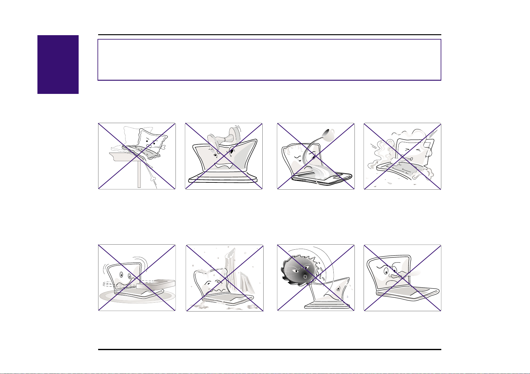
Caring Information
I. Introduction
CAUTION! The following safety precautions will increase the life of the Notebook PC. Follow all precautions and
instructions. Except as described in this manual, refer all servicing to qualified personnel. Do not use damaged power
cords, accessories, or other peripherals. Do not use strong solvents such as thinners, benzene or other chemicals on or
near the surface.
Disconnect the AC power and remove the battery pack(s) before cleaning. Wipe the Notebook PC using a clean cellulose sponge or chamois cloth dampened with a solution of non-abrasive detergent and a few drops of warm water and
remove any extra moisture with a dry cloth.
DO NOT place on uneven
or unstable work surfaces.
Seek servicing if the casing has been damaged.
DO NOT expose to
strong magnetic fields.
DO NOT place or drop objects on top and do not shove
any foreign objects into th e
Notebook PC.
DO NOT expose to extreme temperatures (below 32˚F/
0˚C or above 122˚F/50˚C) or to direct sunlight.
DO NOT expose to liquids,
rain, or moisture. Seek servicing if liquid has been
spilled into the Notebook PC.
12 Notebook PC User’s Manual
DO NOT expose to dirty
or dusty environments.
DO NOT press or touch
the display panel.

Transporting the Notebook PC
To prepare the Notebook PC for transport, you should turn it off and disconnect all external peripherals to prevent
damage to the connectors. The hard disk drive’s head retracts when the power is turned off to prevent scratching of the
hard disk surface during transport. Therefore, you should not transport the Notebook PC while the power is still on.
Close the display panel and check that it is latched securely to the computer to protect the keyboard and display panel.
Floppy Disks
Make sure that the 1.44MB floppy disk drive does not contain a diskette when transporting the Notebook PC. When a
diskette is inserted into the floppy drive, the eject button protrudes out. If you attempt to transport the Notebook PC with
a diskette in the drive, you risk damaging the eject button and also risk scratching the surface of the diskette when the
floppy disk drive is jolted.
Protection
Use a carrying case such as the one supplied with your Notebook PC to protect it from dirt, water, shock, and scratches.
Battery
If you intend to use battery power, be sure to fully char ge your battery pack and any optional battery packs before going
on long trips. Remember that the AC adapter char ges the battery pack as long as it is plugged into the computer and an
AC power source. When the AC adapter is inserted, an orange LED will blink to show char ging and will become solid
when the battery is fully charged. Be aware that it takes much longer to charge the battery pack when the Notebook PC
is in use.
Opening the Display Panel
Two spring-loaded latches on the display panel lock the display panel in the closed position when the Notebook PC is
not in use. T o open the display panel, slide both of the display panel latches outward with your thumbs and then raise the
display panel with your thumbs and forefingers while holding the latches outward. You may then slowly adjust the
display panel to a comfortable viewing position.
I. Introduction
CAUTION! Do not force the display panel down to the table or else the hinges will break!
13Notebook PC User’s Manual

SECTION 2
COMPONENTS
Top Side
II. Components
Display Panel Latches
Display Panel
Microphone
PC Card
(Optional)
~
@
!
#
$
%
^
TV
&
*
_
)
(
+
{
}
[]
"
Keyboard
Stereo Speakers
Touchpad
Touchpad buttons
14 Notebook PC User’s Manual
Status Panel
CD-ROM Drive
\
Battery Lock
Battery Cloth Tab
Battery
Compartment Door
Battery Pack

Top Component Descriptions
The following describes the top components of the Notebook PC as shown by the picture on the previous page.
Display Panel Latches: The display panel latches lock the display panel in the closed position.
Display Panel: The display panel uses active matrix TFT LCD technology and provides viewing like that of desktop
monitors.
Microphone: The built-in microphone provides a source for inputting mono audio.
Status Panel: The display panel provides information on the Notebook PC’s AC-in, battery charging, battery gauge,
hard disk/CD-ROM/floppy access, PC card, suspend, caps lock, and scroll lock statuses.
PCMCIA Card: (see Left Side)
CD-ROM Drive: (see Right Side)
Keyboard: The keyboard provides 19mm full sized keys with 3mm travel and palm rest. W indows function keys also
help decrease navigation time.
Stereo Speakers: The two built-in speakers allow you to hear stereo audio without additional attachments.
Battery Lock: (see Right Side)
Touchpad: The touchpad pointing device with its two buttons allows the same functions as a desktop mouse.
Battery Pack: The battery pack is made of 9 Lithium-Ion cells. One battery pack will provide about 4.8A at 52W. The
system’s internal charger will automatically recharge the battery pack when it is connected to the AC adapter. By using
the power management features, battery power can last approximately 3.5 to 7 hours. The battery pack takes approximately 3 hours to fully recharge when turned off and 5 hours when in use. Battery drain and charging depends on
environment conditions and how the notebook is used. There is a low power warning from speakers and flashing battery
gauge on status indicator .
Battery Lock: (see Right Side)
Battery Cloth Tab: The battery cloth tab is used to pull out the battery pack.
Battery Compartment Door: The battery compartment door covers the battery compartment to protect against dirt.
II. Components
15Notebook PC User’s Manual
Front/Rear Illustrations
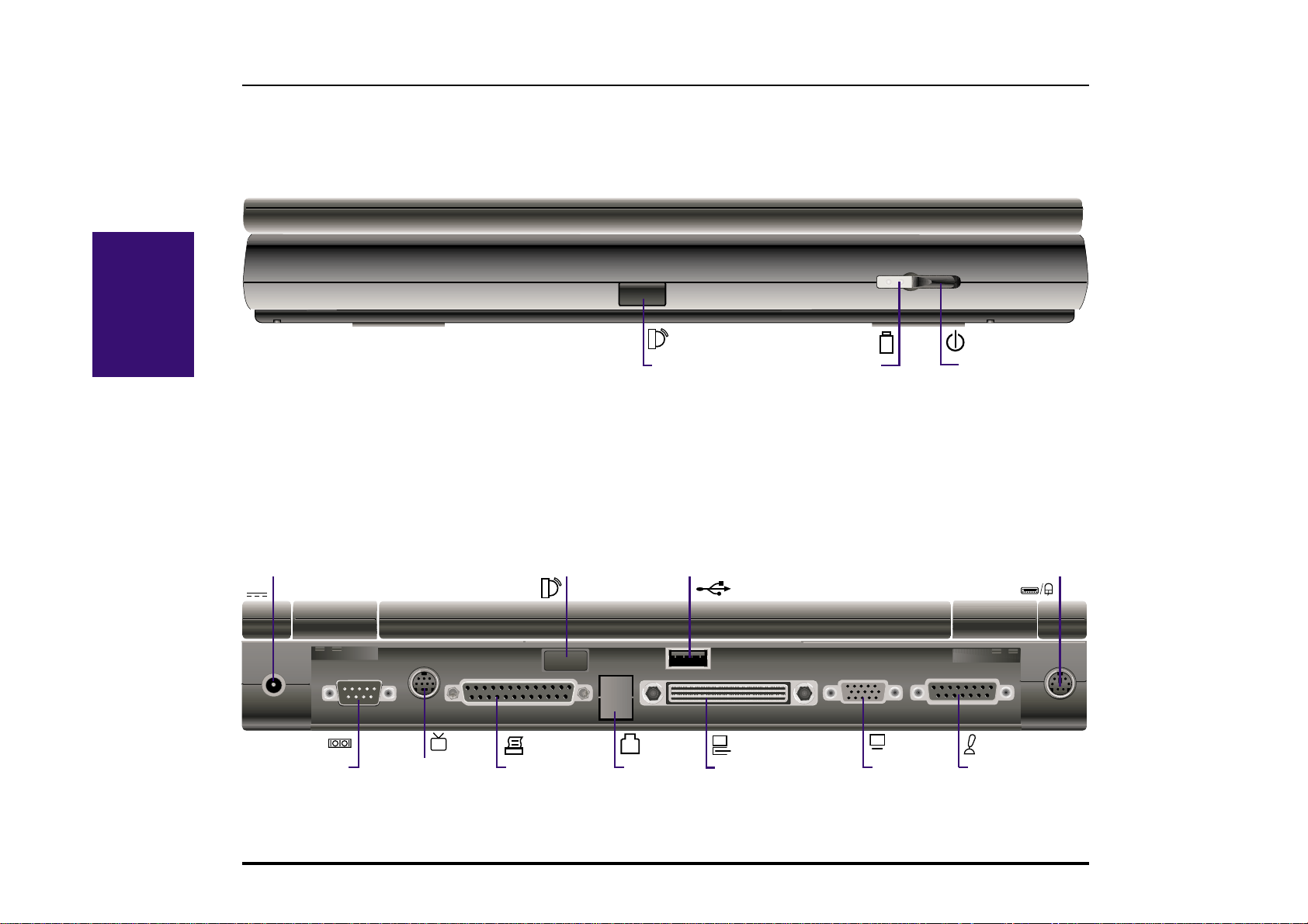
Front Side
Refer to the diagram below to identify the components on the front side of the Notebook PC.
II. Components
Infrared Port
LED Indicators
Rear Side
Refer to the diagram below to identify the components on the rear side of the Notebook PC.
DC Input
DC IN
Serial Port
TV
V ideo Out
Infrared Port
Parallel Port
USB Port
Modem
Port
Docking Connector
VGA Port
Power Switch
(slides to the right)
PS/2 Keyboard/Mouse
Port
Game/MIDI Port
16 Notebook PC User’s Manual

Front/Rear Component Descriptions
Front Side
The following describes the front components to the Notebook PC as shown by the picture on the previous page.
Infrared Port: The infrared (IrDA) communication port allows wireless data transfers through the front.
LED Indicators: The orange LED will blink when the battery pack is charging. The Green LED will be lit
when the power is on and blink when in standby (suspend) mode.
Power Switch: The power switch is used to turn the power ON and OFF. The momentary switch slides to the
right and springs back to the left. Turning ON the power requires about one second and about two seconds to
turn OFF the power.
Rear Side
The following describes the rear components to the Notebook PC as shown by the picture on the previous page.
DC IN
DC Input: The supplied AC adapter converts AC power to DC power for use with this jack.
Serial Port: The 9-pin D-Sub serial port supports serial devices such as a drawing tablet, mouse, or modem.
Video Out: The video out port supports video display devices such as a video recorder , television, or projector
TV
through an S-Video (SVHS) connector (or RCA connector using the supplied adapter).
Parallel Port: The 25-pin D-Sub parallel/printer port supports parallel devices such as a printer or ZIP® drive.
this port also supports connection of the supplied floppy disk drive module using the supplied cable.
II. Components
Infrared Port: The infrared (IrDA) communication port allows wireless data transfers through the rear.
Modem Port: Knockout panel for an optional built-in 56K V.90 modem using a standard RJ11 phone connector .
USB Port: The Universal Serial Bus (USB) port supports several USB compatible devices such as keyboards,
pointers, modems, and printers connected in series.
Docking Connector - The docking connector allows the Notebook PC to connect to a base unit through a
single 240-pin connector . The base unit can attach to desktop peripherals at all times such as keyboard, mouse,
monitor, network, modem, and other devices.
VGA Port - The 15-pin D-Sub VGA port supports a standard VGA-compatible device such as a monitor or
projector.
Game/MIDI Port - The 15-pin D-Sub Game/MIDI port supports a joystick, gamepad, or MIDI devices.
PS/2 Keyboard/Mouse Port - The PS/2 keyboard/mouse port is for connecting an external PS/2 mouse or
PS/2 keyboard to the Notebook PC if you do not want to use the built-in touchpad and keyboard.
17Notebook PC User’s Manual
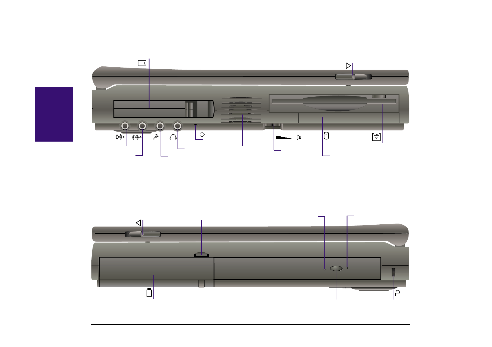
Left/Right Illustrations
Left Side
Refer to the diagram below to identify the components on the left side of the Notebook PC.
II. Components
Audio Line-Out
Right Side
Refer to the diagram below to identify the components on the right side of the Notebook PC.
2 PCMCIA Sockets
Headphone Jack
Microphone-InAudio Line-In
reset
Reset Button
Cooling Fan
Volume Knob
Display Latch
(slides to the right)
Floppy Disk Drive
Hard Disk Drive
Display Latch
(slides to the left)
Battery Compartment
Battery Lock Emergency Eject
18 Notebook PC User’s Manual
CD-ROM Eject
CD Activity LED
K
Kensington Lock

Left/Right Component Descriptions
Left Side
The following describes the left-side components to the Notebook PC as shown by the picture on the previous page.
PCMCIA: PCMCIA 2.1 compliant sockets for two Type I, Type II, or one Type III PC cards are available on
every model. Both sockets support 32-bit CardBus and Zoomed Video on the lower socket to accommodate
any Notebook PC expansion options, including memory cards, fax/modems, hard disks, SCSI adapters, and
high-speed network adapters.
Display Latch: The display latch is used to lock the display panel in the closed position. Slide both latches
forward to unlock the display panel.
Audio Line-Out: The stereo audio line-out is not amplified and is used to connect the Notebook PC’s audio
out to amplified speakers.
Audio Line-In: The stereo audio-in is used to connect external audio sources to the Notebook PC.
Headphone-Out: The stereo headphone jack is amplified and is used to connect a headphone.
Microphone-In: The mono microphone jack is used to connect an external microphone.
Cooling Fan: The cooling fan turns on when the temperature rises past a set threshold. The cooling fan is an
extra feature needed for upgrading to faster processors in the future.
Volume Knob: The volume knob allows adjustment of the built-in speakers’ audio volume level.
Hard Disk Drive: A removable 2.5” UltraDMA/33 IDE hard disk drive is provided with 3.2GB capacity.
Optional 4GB, 5GB, 6.4GB, and 8GB are available.
Floppy Disk Drive: Built-in standard 1.44MB floppy disk drive with Japanese 3-mode support.
reset
Reset Button: Resets the system in case the Notebook PC hangs and CTRL-AL T-DEL & powering OFF does not work.
II. Components
Right Side
The following describes the right-side components to the Notebook PC as shown by the picture on the previous page.
Display Latch: The display latch is used to lock the display panel in the closed position.
Battery Lock: The battery lock is used to secure the battery pack in place when the battery pack is inserted.
Emergency Eject: The CD-ROM emergency eject is used to eject a CD in case the electronic eject does not
work. Do not use this in place of the electronic eject. Electronic eject may be initialized by the CD-ROM eject
button or software.
CD Activity LED: The activity LED blinks proportionally to the CD-ROM drive activity.
Battery Compartment: The battery compartment has a door which houses the battery pack.
CD-ROM Eject: The CD-ROM eject is an electronic eject button for opening the CD-ROM tray.
Kensington® Lock: The Kensington® lock allows the Notebook PC to be secured using Kensington® Note-
K
book PC security products.
19Notebook PC User’s Manual
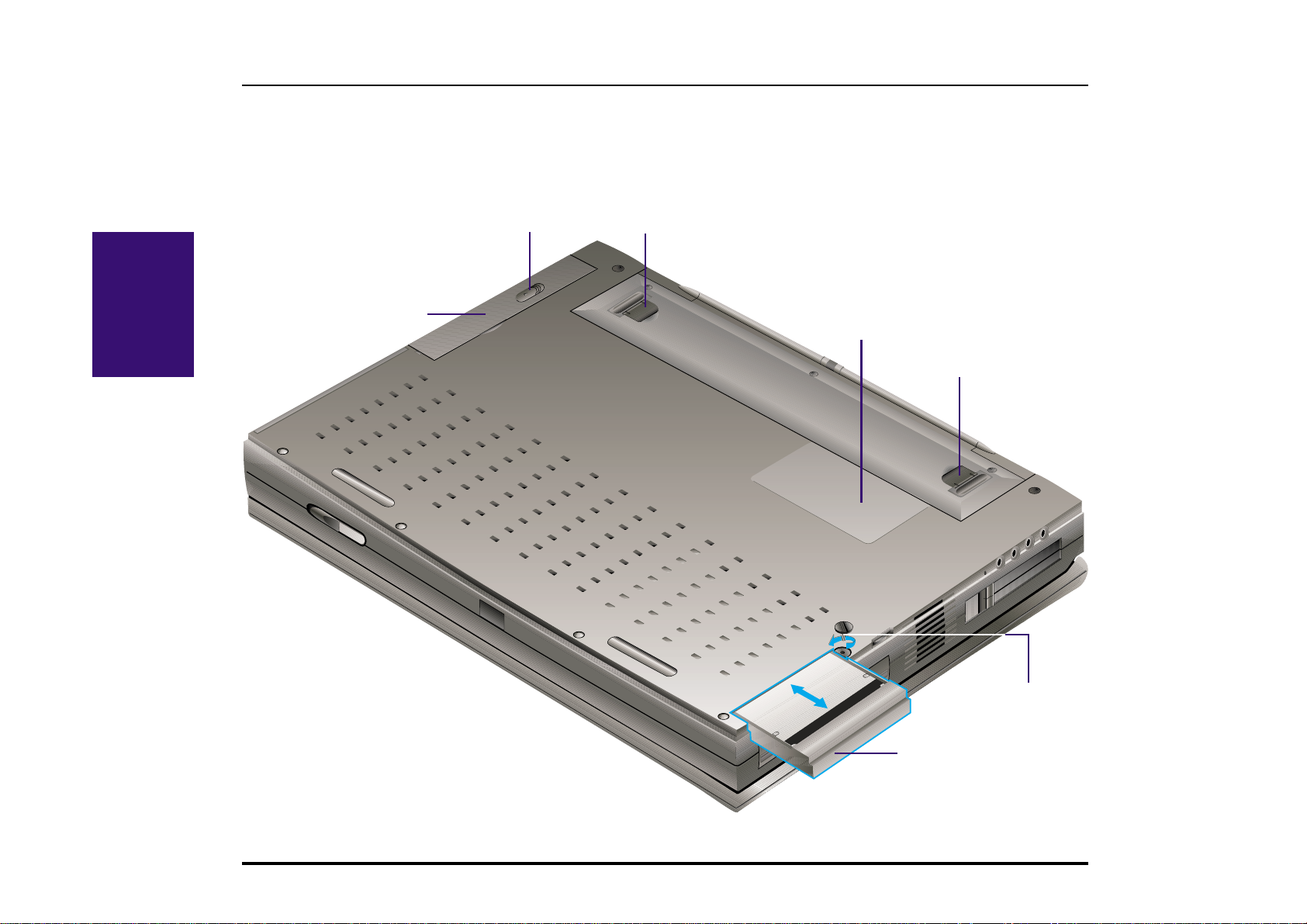
Bottom Illustration
Bottom Side
Refer to the diagram below to identify the components on the bottom side of the Notebook PC.
II. Components
CD-ROM Latch
(slides toward back)
Tilting Leg
CD-ROM Drive
Memory Compartment
T ilting Leg
Hard Disk Drive Scr ew
Hard Disk Drive
20 Notebook PC User’s Manual

Bottom Component Descriptions
Bottom Side
The following describes the bottom components to the Notebook PC as shown by the picture on the previous page.
CD-ROM Latch: The CD-ROM latch locks the CD-ROM in place when inserted. Slide the latch toward the back of
the Notebook PC to release the lock.
CD-ROM Drive: (see right side)
Tilting Legs: The two legs on the bottom of the Notebook PC can be flipped out to provide a comfortable typing angle.
This reduces stress to the hands and wrists while typing.
Memory Compartment: The memory compartment holds the memory expansion sockets. The memory compartment
is to be opened by an authorized service agent only .
Hard Disk Drive Screw: The hard disk drive screw locks the hard disk drive in place when inserted.
Hard Disk Drive: (see left side)
CAUTION! Be sure that the hard disk drive screw is properly secured when transporting the Notebook PC. W ithout
the screw , the hard disk drive may fall out or have partial connection which could result in data loss.
II. Components
21Notebook PC User’s Manual
 Loading...