

Page 1
Notebook PC User Manual
July 2011
E6621
Page 2

2
Notebook PC User Manual
Table of Contents
Table of Contents ............................................................................................... 2
Chapter 1: Introducing the Notebook PC
About This User’s Manual ................................................................................ 6
Notes for This Manual ....................................................................................... 6
Safety Precautions ............................................................................................. 7
Preparing your Notebook PC .......................................................................11
Chapter 2: Knowing the parts
Top Side ...............................................................................................................14
Bottom Side ........................................................................................................17
Right Side ............................................................................................................19
Left Side ...............................................................................................................21
Rear Side ..............................................................................................................23
Front Side ............................................................................................................24
Chapter 3: Getting Started
Power System ....................................................................................................26
Using AC Power ...............................................................................................26
Using Battery Power ......................................................................................28
Battery Care ......................................................................................................29
Powering ON the Notebook PC .................................................................30
The Power-On Self Test (POST) ..................................................................30
Checking Battery Power ...............................................................................32
Charging the Battery Pack ...........................................................................33
Power Options .................................................................................................34
Power Management Modes .......................................................................36
Sleep and Hibernate ......................................................................................36
Thermal Power Control .................................................................................37
Special Keyboard Functions .........................................................................38
Colored Hot Keys (on selected models) .................................................38
Microsoft Windows Keys ..............................................................................40
Multimedia Control Keys (on selected models) ...................................41
Switches and Status Indicators ...................................................................42
Switches .............................................................................................................42
Status Indicators .............................................................................................43
Page 3

Notebook PC User Manual
3
Chapter 4: Using the Notebook PC
Pointing Device .................................................................................................46
Using the Touchpad .......................................................................................47
Touchpad Usage Illustrations .....................................................................48
Caring for the Touchpad ..............................................................................51
Automatic Touchpad Disabling .................................................................51
Storage Devices ................................................................................................ 53
Flash Memory Card Reader .........................................................................53
Memory (RAM) .................................................................................................54
Connections .......................................................................................................55
Network Connection .....................................................................................55
Wireless LAN Connection (on selected models) .................................57
Windows Wireless Network Connection ................................................59
Bluetooth Wireless Connection(on selected models) .......................61
USB Charger+ ...................................................................................................64
Instant On .........................................................................................................65
Appendix
Operating System and Software ...............................................................A-2
System BIOS Settings ..................................................................................A-3
Common Problems and Solutions .........................................................A-6
Recovering Your Notebook PC ............................................................... A-12
Using Recovery Partition ....................................................................... A-12
Using Recovery DVD (on selected models) ...................................... A-13
Internal Modem Compliancy (on selected models) ....................... A-15
Declarations and Safety Statements .................................................... A-19
Federal Communications Commission Statement ........................ A-19
FCC Radio Frequency (RF) Exposure Caution Statement ............ A-20
Declaration of Conformity(R&TTE directive 1999/5/EC) .............. A-20
CE Mark Warning ........................................................................................ A-21
IC Radiation Exposure Statement for Canada ................................. A-21
Wireless Operation Channel for Different Domains ...................... A-22
France Restricted Wireless Frequency Bands .................................. A-22
UL Safety Notices ....................................................................................... A-24
Power Safety Requirement .................................................................... A-25
Page 4

4
Notebook PC User Manual
TV Tuner Notices (on selected models) ............................................. A-25
REACH A-25
Nordic Lithium Cautions (for lithium-ion batteries) ...................... A-26
Macrovision Corporation Product Notice ......................................... A-27
CTR 21 Approval(for Notebook PC with built-in Modem) .......... A-28
European Union Eco-label ...................................................................... A-30
Global Environmental Regulation Compliance and Declaration A-31
ASUS Recycling/Takeback Services ..................................................... A-31
Copyright Information .............................................................................. A-32
Limitation of Liability ................................................................................. A-33
Service and Support ................................................................................... A-33
Page 5

1
Chapter 1:
Introducing the
Notebook PC
Page 6

6
Notebook PC User Manual
About This User’s Manual
You are reading the Notebook PC User’s Manual. This User’s Manual
provides information regarding the various components in the
Notebook PC and how to use them. The following are major sections
of this User’s Manual:
1. Introducing the Notebook PC
Introduces you to the Notebook PC and this User’s Manual.
2. Knowing the Parts
Gives you information on the Notebook PC’s components.
3. Getting Started
Gives you information on getting started with the Notebook PC.
4. Using the Notebook PC
Gives you information on using the Notebook PC’s components.
5. Appendix
Introduces you to optional accessories and gives additional
information.
The actual bundled operating system and applications differ by
models and territories. There may be differences between your
Notebook PC and the pictures shown in this manual. Please
accept your Notebook PC as being correct.
Notes for This Manual
A few notes and warnings are used throughout this guide, allowing
you to complete certain tasks safely and effectively. These notes have
different degrees of importance as follows:
WARNING! Important information that must be followed for safe
operation.
IMPORTANT! Vital information that must be followed to prevent
damage to data, components, or persons.
TIP: Tips for completing tasks.
NOTE: Information for special situations.
Page 7

Notebook PC User Manual
7
Safety Precautions
The following safety precautions will increase the life of the
Notebook PC. Follow all precautions and instructions. Except as
described in this manual, refer all servicing to qualified personnel.
Battery safety warning:
DO NOT throw the
battery in fire. DO NOT
short circuit the contacts.
DO NOT disassemble the
battery.
DO NOT leave the
Notebook PC on your lap
or any part of the body
to prevent discomfort
or injury from heat
exposure.
DO NOT expose to dirty
or dusty environments.
DO NOT operate during a
gas leak.
DO NOT expose to
strong magnetic or
electrical fields.
DO NOT expose to or
use near liquids, rain,
or moisture. DO NOT
use the modem during
electrical storms.
DO NOT press or touch
the display panel. Do not
place together with small
items that may scratch or
enter the Notebook PC.
DO NOT place on
uneven or unstable work
surfaces. Seek servicing
if the casing has been
damaged.
DO NOT place or drop
objects on top and
do not shove any
foreign objects into the
Notebook PC.
Disconnect the AC power and remove the battery pack(s) before
cleaning. Wipe the Notebook PC using a clean cellulose sponge
or chamois cloth dampened with a solution of nonabrasive
detergent and a few drops of warm water and remove any extra
moisture with a dry cloth.
Page 8

8
Notebook PC User Manual
SAFE TEMP: This
Notebook PC should
only be used in
environments with
ambient temperatures
between 5°C (41°F) and
35°C (95°F).
DO NOT carry or cover
a Notebook PC that
is powered ON with
any materials that will
reduce air circulation
such as a carrying bag.
DO NOT throw the Notebook PC in municipal waste. This
product has been designed to enable proper reuse of parts
and recycling. The symbol of the crossed out wheeled bin
indicates that the product (electrical, electronic equipment
and mercury-containing button cell battery) should not
be placed in municipal waste. Check local regulations for
disposal of electronic products.
DO NOT throw the battery in municipal waste. The symbol
of the crossed out wheeled bin indicates that the battery
should not be placed in municipal waste.
INPUT RATING: Refer to
the rating label on the
bottom of the Notebook
PC and be sure that your
power adapter complies
with the rating.
Incorrect installation
of battery may cause
explosion and damage
the Notebook PC.
DO NOT use damaged
power cords, accessories,
or other peripherals.
DO NOT use strong
solvents such as
thinners, benzene, or
other chemicals on or
near the surface.
Page 9

Notebook PC User Manual
9
Transportation Precautions
To prepare the Notebook PC for transport, you should turn it OFF
and disconnect all external peripherals to prevent damage to
the connectors. The hard disk drive’s head retracts when the power
is turned OFF to prevent scratching of the hard disk surface during
transport. Therefore, you should not transport the Notebook PC
while the power is still ON. Close the display panel and check that
it is latched securely in the closed position to protect the keyboard
and display panel.
CAUTION! The Notebook PC’s surface is easily dulled if not
properly cared for. Be careful not to rub or scrape the Notebook
PC surfaces.
Sound Pressure warning
Excessive sound pressure from earphones or headphones can cause
hearing damage or loss. Adjustment of the volume control as well as
the equalizer to settings other than the center position may increase
the earphones or headphones output voltage and the sound
pressure level.
DC Fan warning
Please note that the DC fan is a moving part that may cause DANGER.
Ensure to keep your body from the moving fan blades.
Adapter Information
Input voltage: 100-240Vac
Input frequency: 50-60Hz
Rating output current: 3.42A
Rating output voltage: 19Vdc
Page 10

10
Notebook PC User Manual
Cover Your Notebook PC
Purchase a carrying bag to protect the Notebook PC from dirt, water,
shock, and scratches.
Charge Your Batteries
If you intend to use battery power, be sure to fully charge your
battery pack and any optional battery packs before going on long
trips. Remember that the power adapter charges the battery pack as
long as it is plugged into the computer and an AC power source. Be
aware that it takes much longer to charge the battery pack when the
Notebook PC is in use.
Airplane Precautions
Contact your airline if you want to use the Notebook PC on the
airplane. Most airlines will have restrictions for using electronic
devices. Most airlines will allow electronic use only between and not
during takeoffs and landings.
CAUTION! There are three main types of airport security
devices: X-ray machines (used on items placed on conveyor
belts), magnetic detectors (used on people walking through
security checks), and magnetic wands (hand-held devices used
on people or individual items). You can send your Notebook
PC and diskettes through airport X-ray machines. However, it
is recommended that you do not send your Notebook PC or
diskettes through airport magnetic detectors or expose them to
magnetic wands.
Page 11

Notebook PC User Manual
11
Preparing your Notebook PC
These are quick instructions for using your Notebook PC.
Installing the Battery Pack
Connecting the Power Adapter
2
1
3
2
1
3
2
1
3
1
2
3
110V-220V
Page 12
12
Notebook PC User Manual
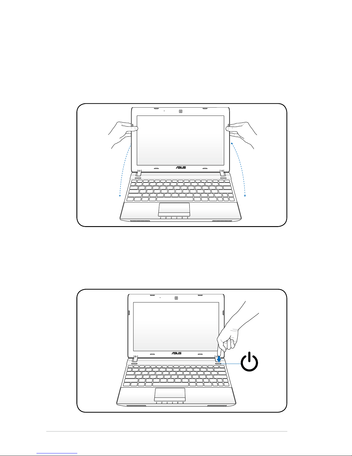
Opening the LCD display panel
1. Carefully lift up the display panel with your thumb.
2. Slowly tilt the display panel forward or backward to a
comfortable viewing angle.
Turning on the Power
1. Push and release the power button located beneath the LCD
display panel.
2. Use [Fn]+[F5] or [Fn]+[F6] to adjust the LCD brightness.
2
1
3
2
1
3
Page 13

2
Chapter 2:
Knowing the parts
Page 14
14
Notebook PC User Manual
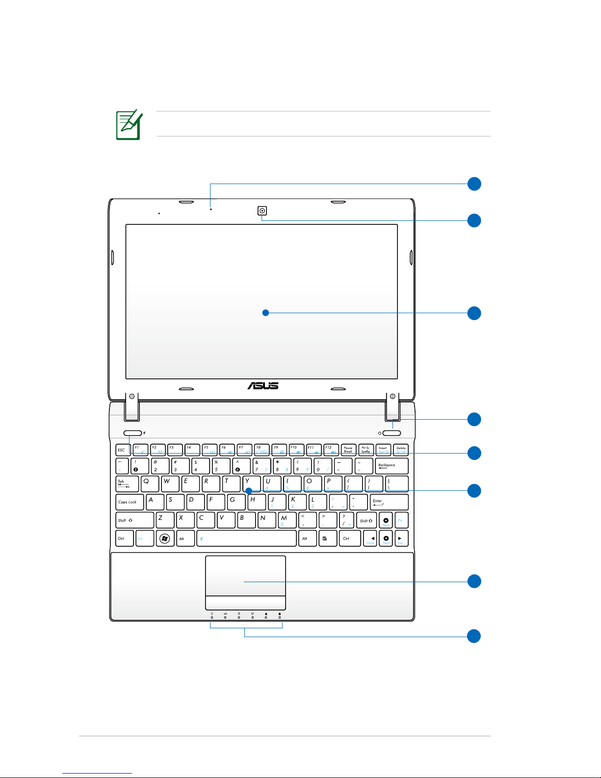
Top Side
The keyboard differs for each territory.
3
2
4
5
6
1
7
8
Page 15

Notebook PC User Manual
15
Microphone (Built-in)
The built-in mono microphone can be used for video
conferencing, voice narrations, or simple audio recordings.
Camera (on selected models)
The built-in camera allows picture taking or video
recording. Can be used with video conferencing and other
interactive applications.
Display Panel
The display panel functions the same as a desktop monitor.
The Notebook PC uses an active matrix TFT LCD, which
provides excellent viewing like that of desktop monitors.
Unlike desktop monitors, the LCD panel does not produce
any radiation or flickering, so it is easier on the eyes. Use
a soft cloth without chemical liquids (use plain water if
necessary) to clean the display panel.
Power Switch
The power switch allows powering ON and OFF the
Notebook PC and recovering from STD. Use the switch once
to turn ON and once to turn OFF the Notebook PC. The
power switch only works when the display panel is opened.
Power4Gear Key (on selected models)
Under the Windows OS, this key functions as the
Power4Gear Hybrid key. The key toggles power savings
between various power saving modes. The power saving
modes control many aspects of the Notebook PC to
maximize performance versus battery time. Applying or
removing the power adapter will automatically switch the
system between AC mode and battery mode. The selected
mode is shown on the display.
1
2
3
4
5
Page 16
16
Notebook PC User Manual
Keyboard
The keyboard provides full-sized keys with comfortable
travel (depth at which the keys can be depressed) and
palm rest for both hands. Two Windows function keys are
provided to help ease navigation in the Windows operating
system.
Touchpad and Buttons
The touchpad with its buttons is a pointing device that
provides the same functions as a desktop mouse. A
software-controlled scrolling function is available after
setting up the included touchpad utility to allow easy
Windows or web navigation.
Status Indicators (front)
Status indicators represent various hardware/software
conditions. See indicator details in Chapter 3.
7
8
6
Page 17
Notebook PC User Manual
17
Bottom Side
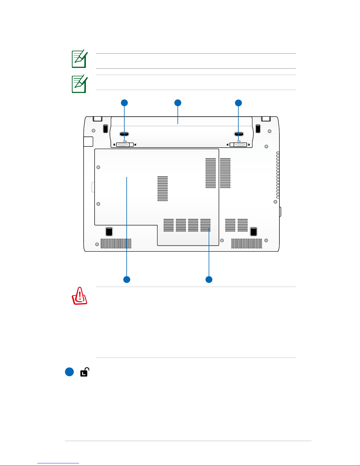
The bottom side may vary in appearance depending on model.
The battery pack size varies depending on model.
The bottom of the Notebook PC can get very hot. Be careful
when handling the Notebook PC while it is in operation or
recently been in operation. High temperatures are normal during
charging or operation. DO NOT USE ON SOFT SURFACES SUCH
AS SOFAS OR BEDS, WHICH MAY BLOCK THE VENTS. DO NOT
PUT THE NOTEBOOK PC ON YOUR LAP OR OTHER PARTS OF
THE BODY TO AVOID INJURY FROM THE HEAT.
1 2
4 5
3
1
Battery Lock - Spring
The spring battery lock is used to keep the battery
pack secured. When the battery pack is inserted, it will
automatically lock. To remove the battery pack, this spring
lock must be held in the unlocked position.
Page 18

18
Notebook PC User Manual
Battery Pack
The battery pack is automatically charged when the
Notebook PC is connected to an AC power source and
maintains power to the Notebook PC when AC power is
not connected. This allows use when moving temporarily
between locations. Battery time varies by usage and by
the specifications for this Notebook PC. The battery pack
cannot be disassembled and must be purchased as a single
unit.
Battery Lock - Manual
The manual battery lock is used to keep the battery pack
secured. Move the manual lock to the unlocked position to
insert or remove the battery pack. Move the manual lock to
the locked position after inserting the battery pack.
Hard Disk Drive Compartment
The hard disk drive is secured in a compartment. Visit an
authorized service center or retailer for information on hard
disk drive upgrades for your Notebook PC. Only purchase
hard disk drives from authorized retailers of this Notebook
PC to ensure maximum compatibility and reliability.
Memory (RAM) Compartment
The memory compartment provides expansion capabilities
for additional memory. Additional memory will increase
application performance by decreasing hard disk access.
The BIOS automatically detects the amount of memory in
the system and configures CMOS accordingly during the
POST (Power-On-Self-Test) process. There is no hardware or
software (including BIOS) setup required after the memory
is installed. Visit an authorized service center or retailer for
information on memory upgrades for your Notebook PC.
Only purchase expansion modules from authorized retailers
of this Notebook PC to ensure maximum compatibility and
reliability.
2
3
4
5
Page 19
Notebook PC User Manual
19
Right Side
1
2
3
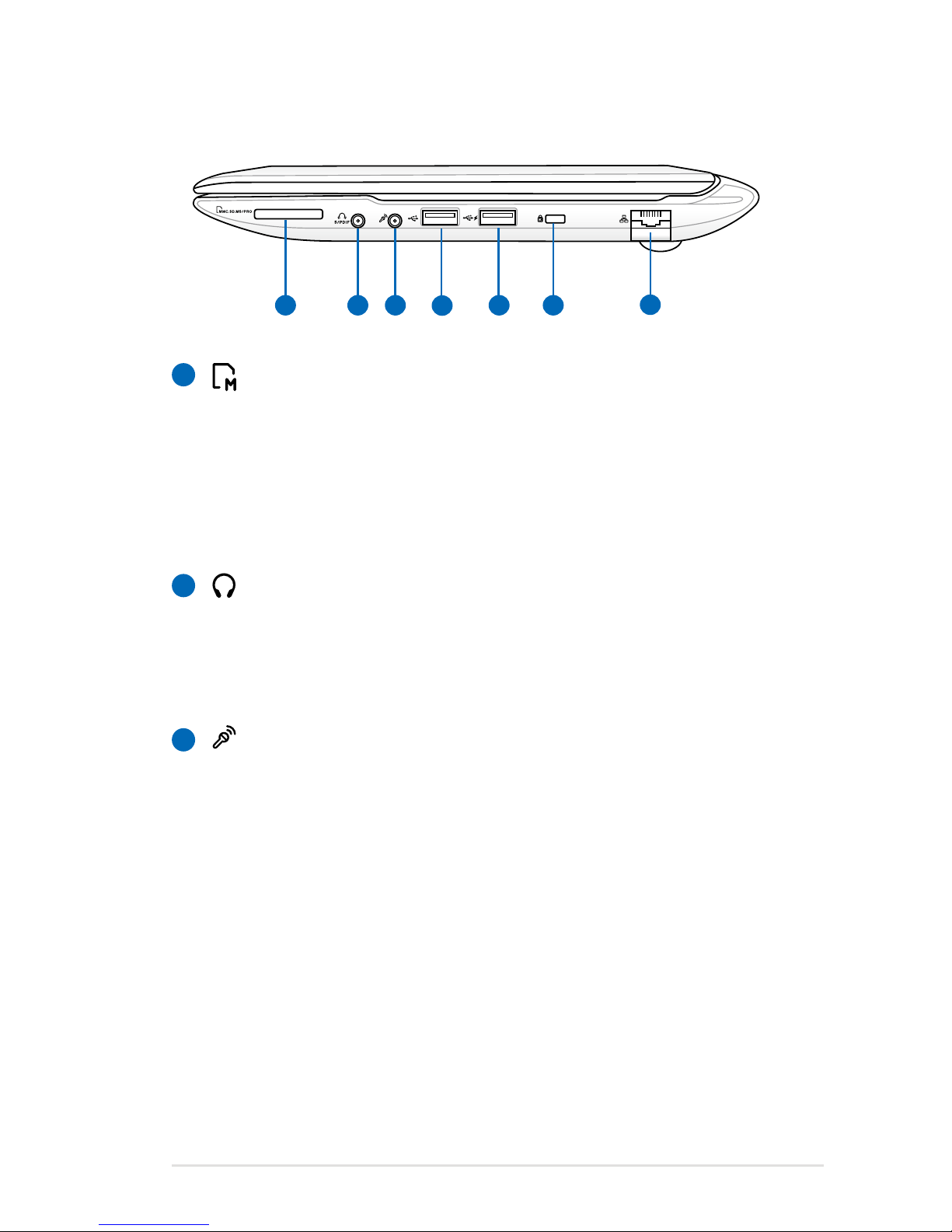
Flash Memory Slot
Normally an external memory card reader must be
purchased separately in order to use memory cards from
devices such as digital cameras, MP3 players, mobile
phones, and PDAs. This Notebook PC has a built-in
high-speed memory card reader that can conveniently read
from and write to many flash memory cards.
Headphone Output Jack
The stereo headphone jack (1/8 inch) is used to connect
the Notebook PC’s audio out signal to amplified speakers
or headphones. Using this jack automatically disables the
built-in speakers.
Microphone Input Jack
The mono microphone jack (1/8 inch) can be used to
connect an external microphone or output signals from
audio devices. Using this jack automatically disables the
built-in microphone. Use this feature for video conferencing,
voice narrations, or simple audio recordings.
21
7
6
4
3 5
Page 20

20
Notebook PC User Manual
5
6
4
USB Port (3.0, on selected models / 2.0)
USB Port (3.0, on selected models / 2.0)
This port also supports USB Charger+ function that helps
charge the connected USB device even when the Notebook
PC is powered off.
Kensington® Lock Port
The Kensington® lock port allows the Notebook PC to
be secured using Kensington® compatible Notebook PC
security products. These security products usually include
a metal cable and lock that prevent the Notebook PC to
be removed from a fixed object. Some may also include a
motion detector to sound an alarm when moved.
LAN Port
The RJ-45 LAN port with eight pins is larger than the RJ-11
modem port and supports a standard Ethernet cable for
connection to a local network. The built-in connector allows
convenient use without additional adapters.
7
Page 21
Notebook PC User Manual
21
Left Side
1
2
3
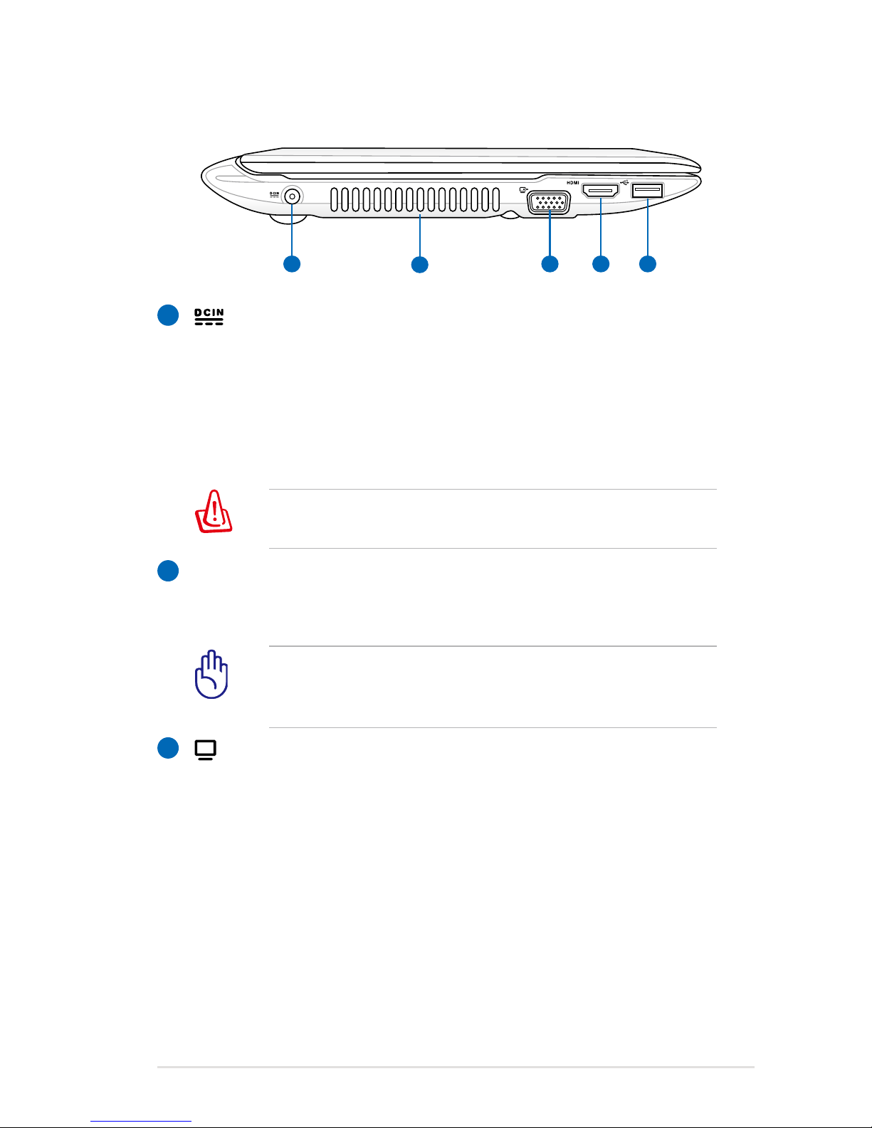
Power (DC) Input
The supplied power adapter converts AC power to DC
power for use with this jack. Power supplied through this
jack supplies power to the Notebook PC and charges the
internal battery pack. To prevent damage to the Notebook
PC and battery pack, always use the supplied power
adapter.
The adapter may become warm to hot when in use. Ensure
not to cover the adapter and keep it away from your body.
Air Vents
The air vents allow cool air to enter and warm air to exit the
Notebook PC.
Ensure that paper, books, clothing, cables, or other objects
do not block any of the air vents or else overheating may
occur.
Display (Monitor) Output
The 15-pin D-sub monitor port supports a standard
VGA-compatible device such as a monitor or projector to
allow viewing on a larger external display.
1
2
4 53
Page 22

22
Notebook PC User Manual
5
4
HDMI
HDMI Port
HDMI (High-Definition Multimedia Interface) is an
uncompressed all-digital audio/video interface between
any audio/video source, such as a set-top box, DVD player,
and A/V receiver and an audio and/or video monitor, such
as a digital television (DTV). Supports standard, enhanced,
or high-definition video, plus multi-channel digital audio
on a single cable. It transmits all ATSC HDTV standards and
supports 8-channel digital audio, with bandwidth to spare
to accommodate future enhancements or requirements.
USB Port 2.0 (3.0, on selected models)
The USB (Universal Serial Bus) port is compatible with USB
devices such as keyboards, pointing devices, cameras, hard
disk drives, printers, and scanners. USB allows many devices
to run simultaneously on a single computer, with some
peripherals acting as additional plug-in sites or hubs. USB
supports hot-swapping of devices so that most peripherals
can be connected or disconnected without restarting the
computer.
Page 23
Notebook PC User Manual
23
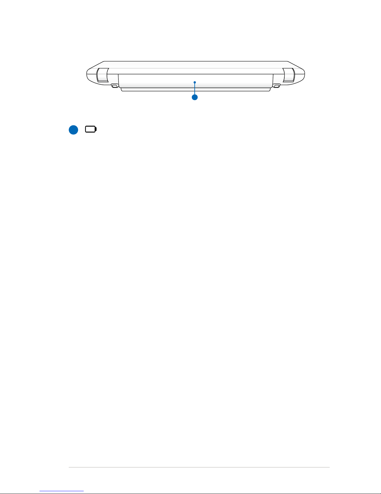
Rear Side
Battery Pack
The battery pack is automatically charged when the
Notebook PC is connected to an AC power source and
maintains power to the Notebook PC when AC power is
not connected. This allows use when moving temporarily
between locations. Battery time varies by usage and by
the specifications for this Notebook PC. The battery pack
cannot be disassembled and must be purchased as a single
unit.
1
1
Page 24
24
Notebook PC User Manual
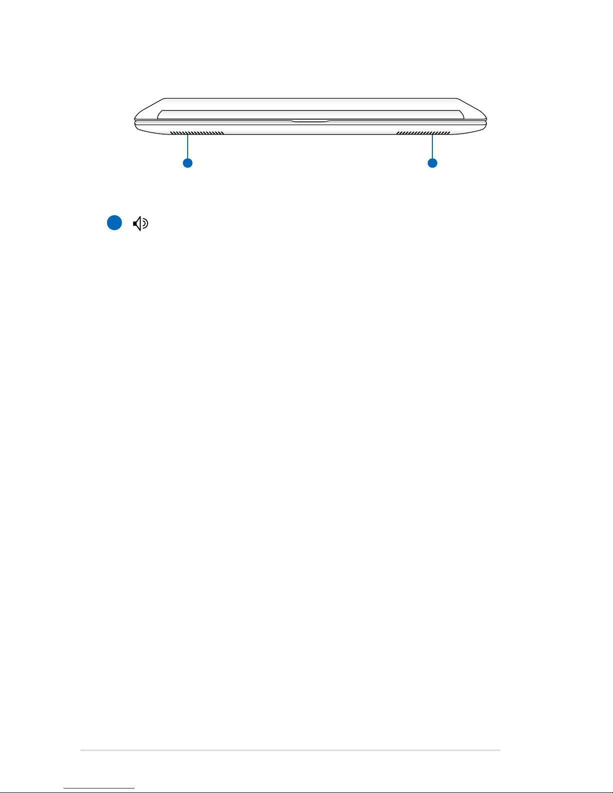
Front Side
Audio Speaker System
The built-in stereo speaker system allows you to hear audio
without additional attachments. The multimedia sound
system features an integrated digital audio controller
that produces rich, vibrant sound (results improved with
external stereo headphones or speakers). Audio features
are software controlled.
1
1 1
Page 25

3
Chapter 3:
Getting Started
Page 26

26
Notebook PC User Manual
Power System
Using AC Power
The Notebook PC power is comprised of two parts, the power
adapter and the battery power system. The power adapter converts
AC power from a wall outlet to the DC power required by the
Notebook PC. Your Notebook PC comes with a universal AC-DC
adapter. That means that you may connect the power cord to any
100V-120V as well as 220V-240V outlets without setting switches
or using power converters. Different countries may require that an
adapter be used to connect the provided US-standard AC power
cord to a different standard. Most hotels will provide universal
outlets to support different power cords as well as voltages. It is
always best to ask an experienced traveler about AC outlet voltages
when bringing power adapters to another country.
You can buy travel kits for the Notebook PC that includes power
and modem adapters for almost every country.
WARNING! DO NOT connect the AC power cord to an AC outlet
prior to connecting the DC plug to the Notebook PC. Doing so
may damage the AC-DC adapter.
1
2
3
110V-220V
Page 27
Notebook PC User Manual
27
IMPORTANT! Damage may occur if you use a different adapter
to power the Notebook PC or use the Notebook PC’s adapter to
power other electrical devices. If there is smoke, burning scent,
or extreme heat coming from the AC-DC adapter, seek servicing.
Seek servicing if you suspect a faulty AC-DC adapter. You may
damage both your battery pack(s) and the Notebook PC with a
faulty AC-DC adapter.
This Notebook PC may come with either a two or three-prong
plug depending on territory. If a three-prong plug is provided,
you must use a grounded AC outlet or use a properly grounded
adapter to ensure safe operation of the Notebook PC.
WARNING! THE POWER ADAPTER MAY BECOME WARM TO HOT
WHEN IN USE. BE SURE NOT TO COVER THE ADAPTER AND KEEP
IT AWAY FROM YOUR BODY.
Unplug the power adapter or switch off the AC outlet to
minimize the power consumption when the Notebook PC is not
in use.
Page 28
28
Notebook PC User Manual
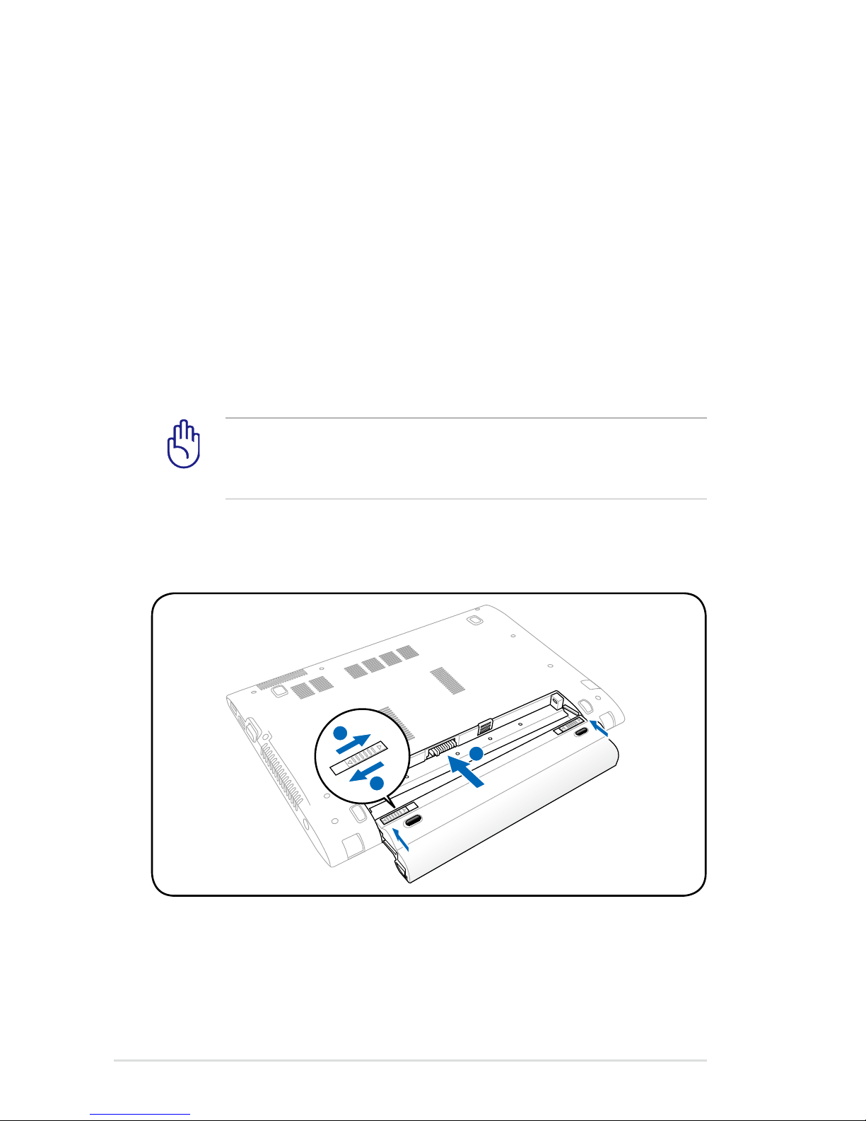
IMPORTANT! Never attempt to remove the battery pack while
the Notebook PC is turned ON, as this may result in the loss of
working data.
To install the battery pack:
Using Battery Power
The Notebook PC is designed to work with a removable battery pack.
The battery pack consists of a set of battery cells housed together.
A fully charged pack will provide several hours of battery life, which
can be further extended by using power management features
through the BIOS setup. Additional battery packs are optional and
can be purchased separately through a Notebook PC retailer.
Installing and Removing the Battery Pack
Your Notebook PC may or may not have its battery pack installed. If
your Notebook PC does not have its battery pack installed, use the
following procedures to install the battery pack.
2
1
3
2
1
3
Page 29
Notebook PC User Manual
29
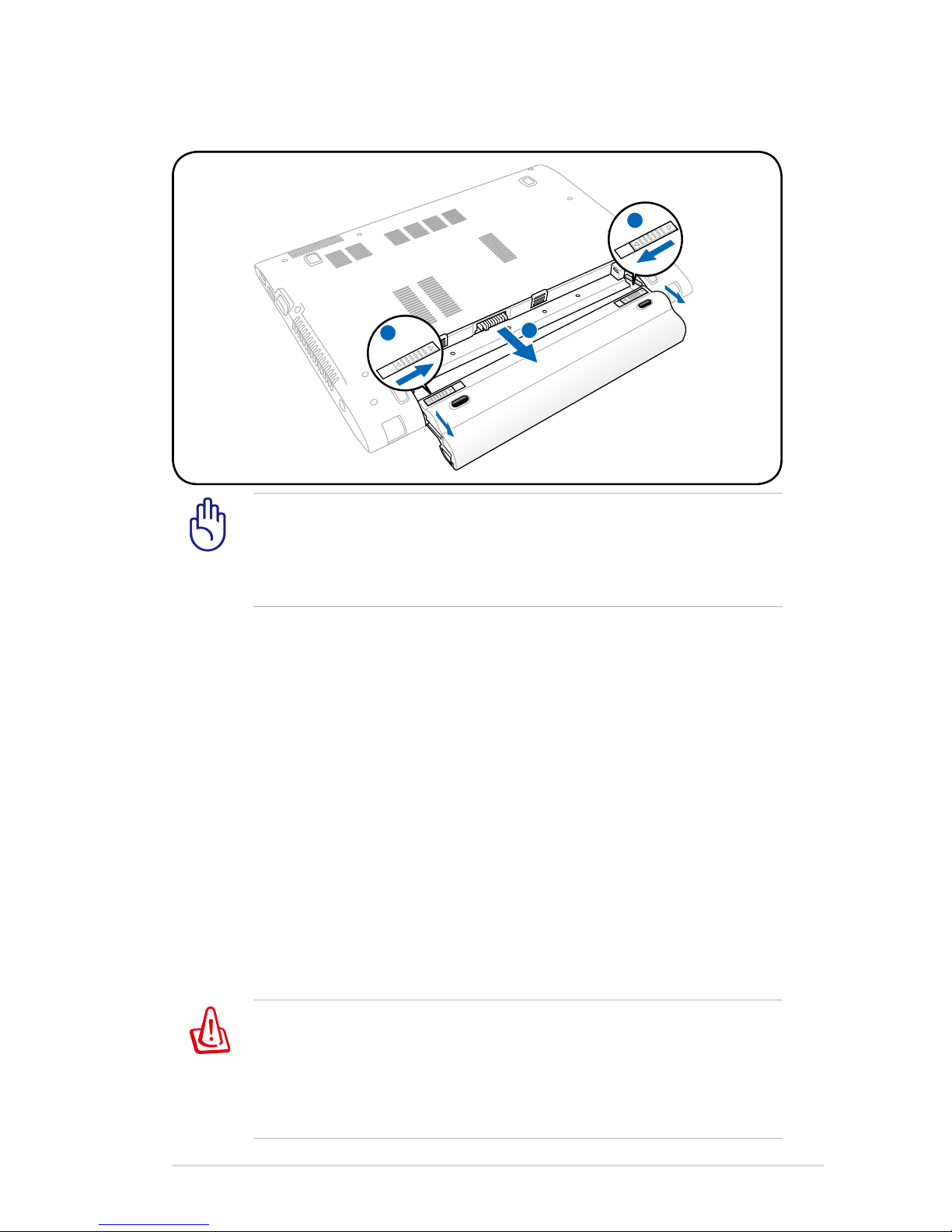
IMPORTANT! Only use battery packs and power adapters
supplied with this Notebook PC or specifically approved by the
manufacturer or retailer for use with this model or else damage
may occur to the Notebook PC.
To remove the battery pack:
WARNING! For safety reasons, DO NOT throw the battery in fire,
DO NOT short circuit the contacts, and DO NOT disassemble the
battery. If there is any abnormal operation or damage to the
battery pack caused by impact, turn OFF the Notebook PC and
contact an authorized service center.
Battery Care
The Notebook PC’s battery pack, like all rechargeable batteries, has
a limit on the number times it can be recharged. The battery pack’s
useful life will depend on your environment temperature, humidity,
and how your Notebook PC is used. It is ideal that the battery be
used in a temperature range between 10˚C and 35˚C (50˚F and
95˚F). You must also take into account that the Notebook PC’s
internal temperature is higher than the outside temperature. Any
temperatures above or below this range will shorten the life of the
battery. But in any case, the battery pack’s usage time will eventually
decrease and a new battery pack must be purchased from an
authorized dealer for this Notebook PC. Because batteries also have
a shelf life, it is not recommended to buy extras for storing.
2
1
3
2
3
1
Page 30

30
Notebook PC User Manual
IMPORTANT! To protect the hard disk drive, always wait at least
5 seconds after turning OFF your Notebook PC before turning it
back ON.
WARNING! DO NOT carry or cover a Notebook PC that is
powered ON with any materials that will reduce air circulation
such as a carrying bag.
Before bootup, the display panel flashes when the power is
turned ON. This is part of the Notebook PC’s test routine and is
not a problem with the display.
Powering ON the Notebook PC
The Notebook PC’s power-ON message appears on the screen when
you turn it ON. If necessary, you may adjust the brightness by using
the hot keys. If you need to run the BIOS Setup to set or modify the
system configuration, press [F2] upon bootup to enter the BIOS
Setup. Press [ESC] and you will be presented with a boot menu with
selections to boot from your available drives.
The Power-On Self Test (POST)
When you turn ON the Notebook PC, it will first run through a
series of software-controlled diagnostic tests called the Power-On
Self Test (POST). The software that controls the POST is installed
as a permanent part of the Notebook PC’s architecture. The POST
includes a record of the Notebook PC’s hardware configuration,
which is used to make a diagnostic check of the system. This record
is created by using the BIOS Setup program. If the POST discovers
a difference between the record and the existing hardware, it will
display a message on the screen prompting you to correct the
conflict by running BIOS Setup. In most cases the record should be
correct when you receive the Notebook PC. When the test is finished,
you may get a message reporting “No operating system found” if the
hard disk was not preloaded with an operating system. This indicates
that the hard disk is correctly detected and ready for the installation
of a new operating system.
Page 31
Notebook PC User Manual
31
IMPORTANT! If warnings are still given during bootup after
running a software disk checking utility, you should take your
Notebook PC in for servicing. Continued use may result in data
loss.
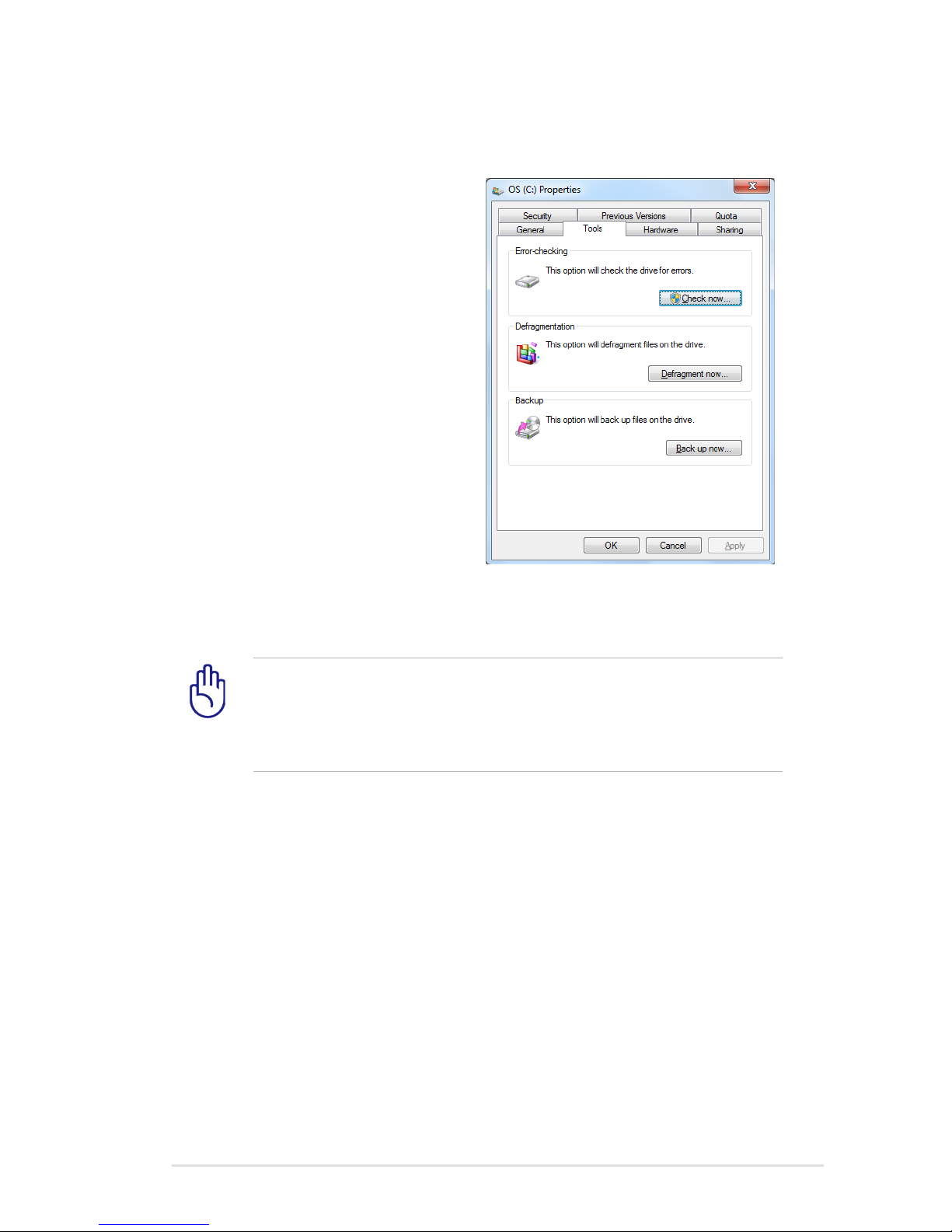
Self Monitoring and Reporting Technology
The S.M.A.R.T. (Self Monitoring
and Reporting Technology)
checks the hard disk drive during
POST and gives a warning
message if the hard disk drive
requires servicing. If any critical
hard disk drive warning is given
during bootup, backup your data
immediately and run Windows
disk checking program. To run
Window’s disk checking program:
click Start > select Computer >
right-click a hard disk drive icon
> choose Properties > click the
Tools tab > click Check Now >
click Start. You can also select “Scan ... sectors” for more effective
scan and repair but the process will run slower.
Page 32
32
Notebook PC User Manual
You will be warned when battery power is low. If you continue
to ignore the low battery warnings, the Notebook PC eventually
enters suspend mode (Windows default uses STR).
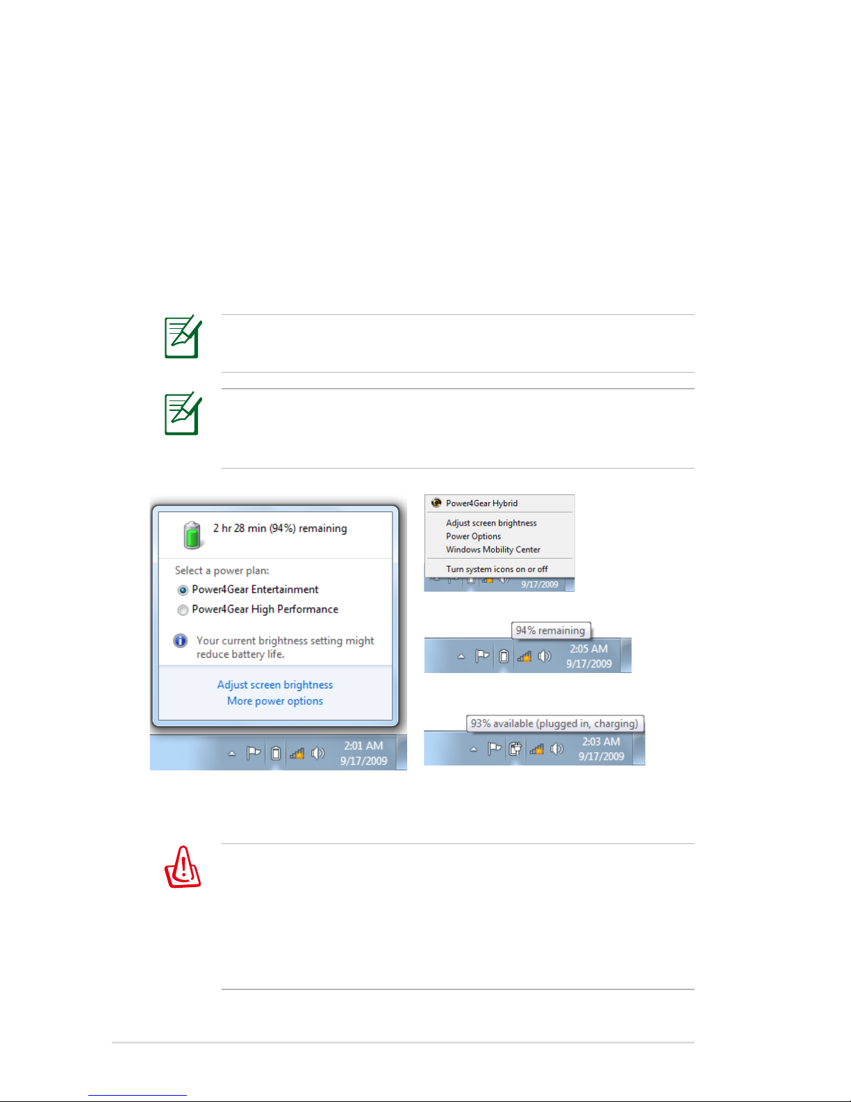
Screen captures shown here are examples only and may not
reflect what you see in your system.
Checking Battery Power
The battery system implements the Smart Battery standard under
the Windows environment, which allows the battery to accurately
report the amount of charge left in the battery. A fully-charged
battery pack provides the Notebook PC a few hours of working
power. But the actual figure varies depending on how you use the
power saving features, your general work habits, the CPU, system
memory size, and the size of the display panel.
Pointer over the battery icon without power adapter.
Pointer over the battery icon with
power adapter.
Right-click the battery icon
Left-click the battery icon
WARNING! Suspend-to-RAM (STR) does not last long when the
battery power is depleted. STR is not the same as power OFF.
STR requires a small amount of power and will fail and lose data
if no power is available due to complete battery depletion or
no power supply (e.g. removing both the power adapter and
battery pack).
Page 33
Notebook PC User Manual
33
WARNING! DO NOT leave the battery pack discharged. The
battery pack will discharge over time. If not using a battery pack,
it must continued to be charged every three months to extend
recovery capacity or else it may fail to charge in the future.
The battery stops charging if the temperature is too high or the
battery voltage is too high.
Charging the Battery Pack
Before you use your Notebook PC on the road, you will have to
charge the battery pack. The battery pack begins to charge as
soon as the Notebook PC is connected to external power using the
power adapter. Fully charge the battery pack before using it for the
first time. A new battery pack must completely charge before the
Notebook PC is disconnected from external power. It takes a few
hours to fully charge the battery when the Notebook PC is turned
OFF and may take twice the time when the Notebook PC is turned
ON. The battery status indicator on the Notebook PC turns OFF when
the battery pack is charged.
The battery starts charging when the charge remaining in
the battery drops below 95%. This prevents the battery from
charging frequently. Minimizing the recharge cycles helps
prolong battery life.
Page 34
34
Notebook PC User Manual
IMPORTANT! To protect the hard drive, wait at least 5 seconds
after turning OFF your Notebook PC before turning it back ON.
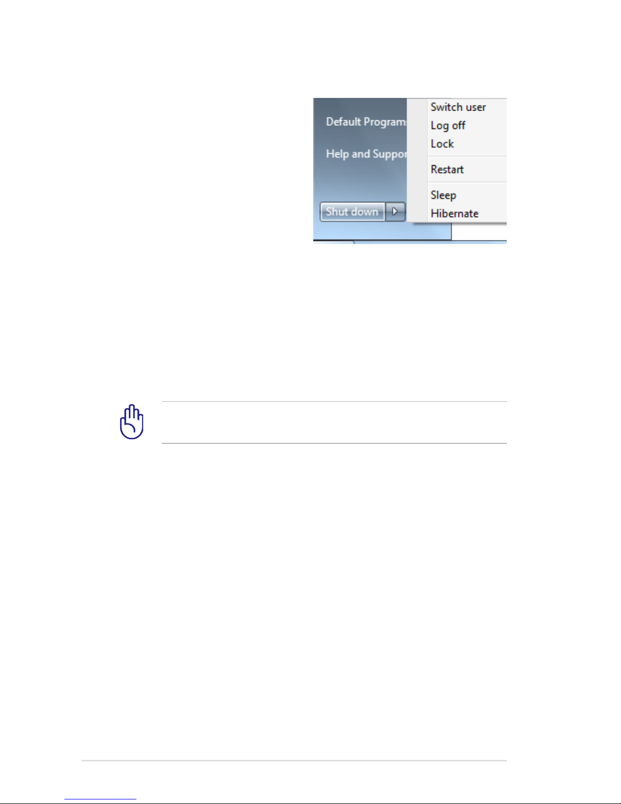
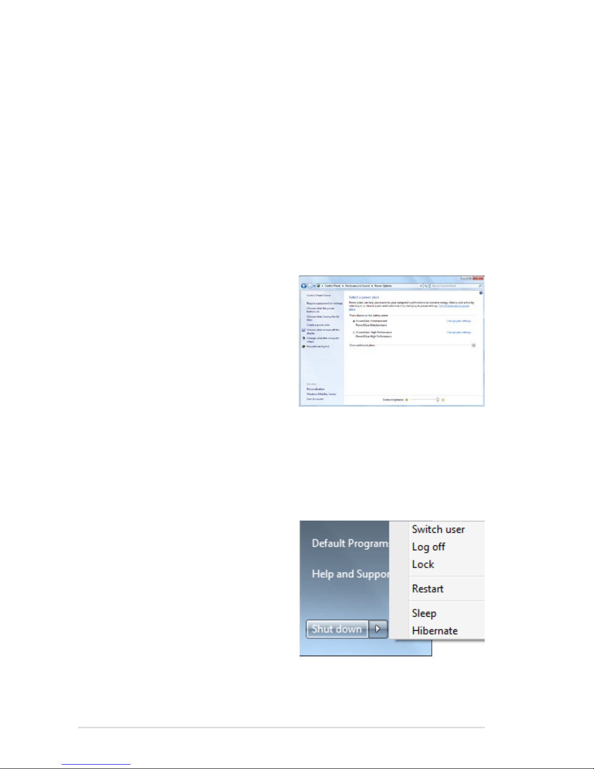
Power Options
The power switch turns ON and
OFF the Notebook PC or putting
the Notebook PC into sleep
or hibernation modes. Actual
behavior of the power switch
can be customized in Windows
Control Panel “Power Options.”
For other options, such as “Switch
User, Restart, Sleep, or Shut Down,” click the arrowhead next to the
lock icon.
Restarting or Rebooting
After making changes to your operating system, you may be
prompted to restart the system. Some installation processes will
provide a dialog box to allow restart. To restart the system manually,
choose Restart.
Page 35
Notebook PC User Manual
35
Emergency Shutdown
In case your operating system cannot properly turn OFF or restart,
there is an additional way to shutdown your Notebook PC:
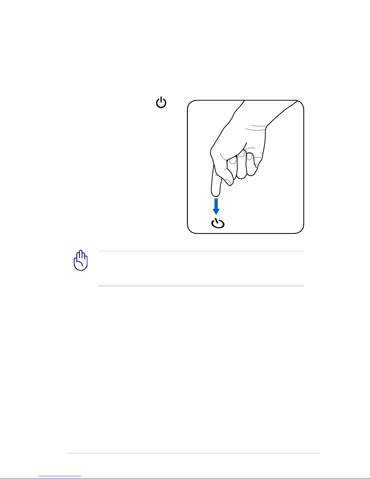
• Hold the power button over
4 seconds.
IMPORTANT! DO NOT use emergency shutdown while data is
being written; doing so can result in loss or destruction of your
data.
Page 36
36
Notebook PC User Manual
Sleep and Hibernate
Power management settings
can be found in the Windows
> Control Panel > Hardware
and Sound > Power Options. In
Power Options, you can define
“Sleep/Hibernate” or “Shut Down”
for closing the display panel
or pressing the power button.
“Sleep” and “Hibernate” saves power when your Notebook PC is not
in use by turning OFF certain components. When you resume your
work, your last status (such as a document scrolled down half way or
email typed half way) will reappear as if you never left. “Shut Down”
will close all applications and ask if you want to save your work if any
are not saved.
Power Management Modes
The Notebook PC has a number of automatic or adjustable power
saving features that you can use to maximize battery life and lower
Total Cost of Ownership (TCO). You can control some of these
features through the Power menu in the BIOS Setup. ACPI power
management settings are made through the operating system.
The power management features are designed to save as much
electricity as possible by putting components into a low power
consumption mode as often as possible but also allow full operation
on demand.
Sleep is the same as Suspend-toRAM (STR). This function stores
your current data and status in
RAM while many components
are turned OFF. Because RAM
is volatile, it requires power to
keep (refresh) the data. Click
the Windows button and the
arrowhead next to the lock icon
to see this option. You can also use the keyboard shortcut [Fn F1]
to activate this mode. Recover by pressing any keyboard key except
[Fn]. (NOTE: The power indicator will blink in this mode.)
Page 37

Notebook PC User Manual
37
Thermal Power Control
There are three power control methods for controlling the Notebook
PC’s thermal state. These power control cannot be configured by
the user and should be known in case the Notebook PC should
enter these states. The following temperatures represent the chassis
temperature (not CPU).
• The fan turns ON for active cooling when the temperature reaches
the safe upper limit.
• The CPU decreases speed for passive cooling when the temperature
exceeds the safe upper limit.
• The system shut down for critical cooling when temperature exceeds the maximum safe upper limit.
Hibernate is the same as Suspend-to-Disk (STD) and stores your
current data and status on the hard disk drive. By doing this, RAM
does not have to be periodically refreshed and power consumption
is greatly reduced but not completely eliminated because
certain wake-up components like LAN needs to remain powered.
“Hibernate” saves more power compared to “Sleep”. Click the Start
button and the arrowhead next to the lock icon to see this option.
Recover by pressing the power button. (NOTE: The power indicator
will be OFF in this mode.)
Page 38
38
Notebook PC User Manual
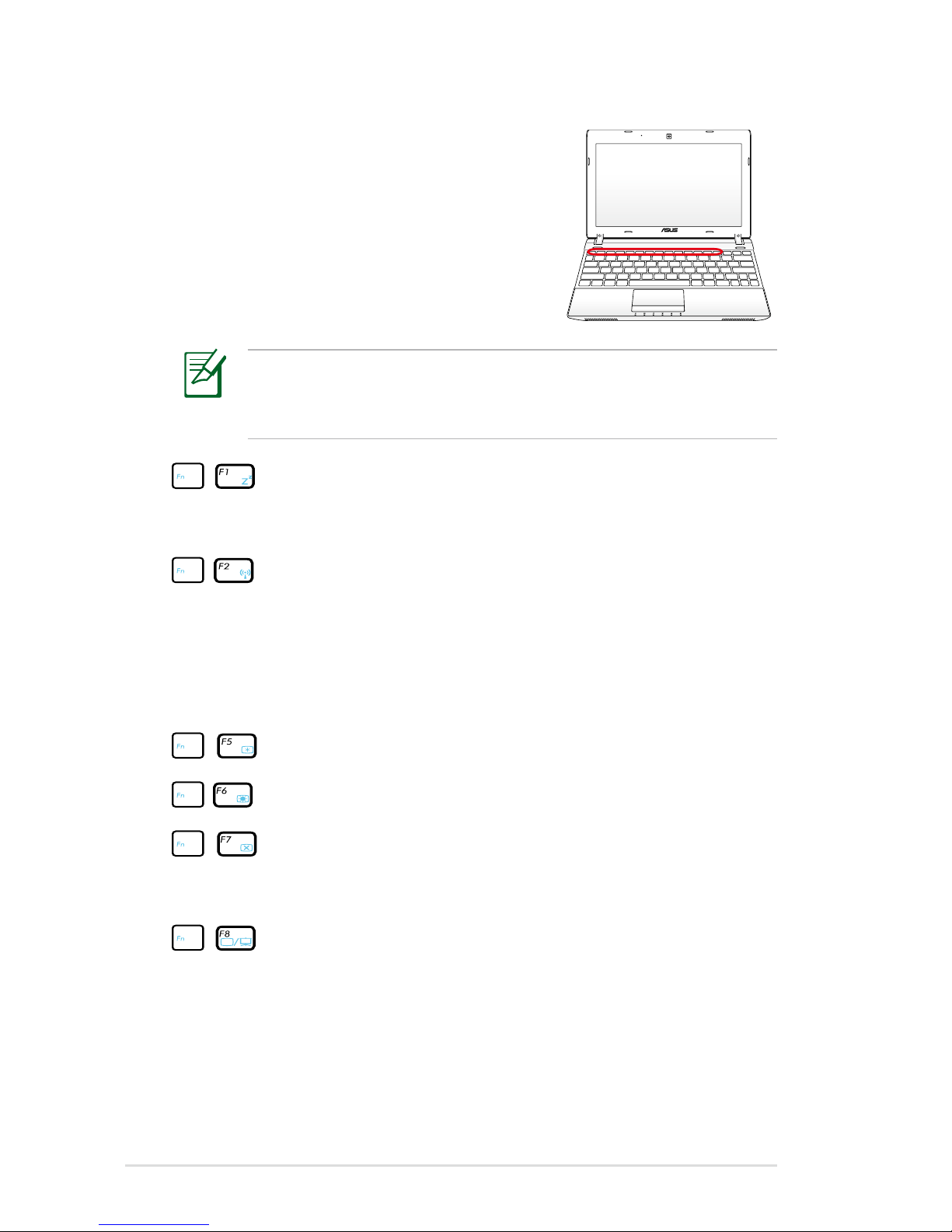
The Hot Key locations on the function keys may vary depending
on model but the functions should remain the same. Follow the
icons instead of the function keys.
Special Keyboard Functions
Colored Hot Keys (on selected models)
The following defines the colored hot keys
on the Notebook PC’s keyboard. The colored
commands can only be accessed by first
pressing and holding the function key while
pressing a key with a colored command.
“ZZ” Icon (F1): Places the Notebook PC in suspend mode
(either Save-to-RAM or Save-to-Disk depending on sleep
button setting in power management setup).
Radio Tower (F2): Wireless Models Only: Toggles the
internal wireless LAN or Bluetooth (on selected models)
ON or OFF with an on-screen-display. When enabled,
the corresponding wireless indicator will light. Windows
software settings are necessary to use the wireless LAN
or Bluetooth.
Sun Down Icon (F5): Decreases the display brightness
Sun Up Icon (F6): Increases the display brightness
LCD Icon (F7): Toggles the display panel ON and OFF. (On
certain models; stretches the screen area to fill the entire
display when using low resolution modes.)
LCD/Monitor Icons (F8): Toggles between the Notebook
PC’s LCD display and an external monitor in this series:
LCD Only -> CRT Only (External Monitor) -> LCD + CRT
(Clone) or LCD + CRT (Extend). (This function does not
work in 256 Colors, select High Color in Display Property
Settings.)
Page 39
Notebook PC User Manual
39
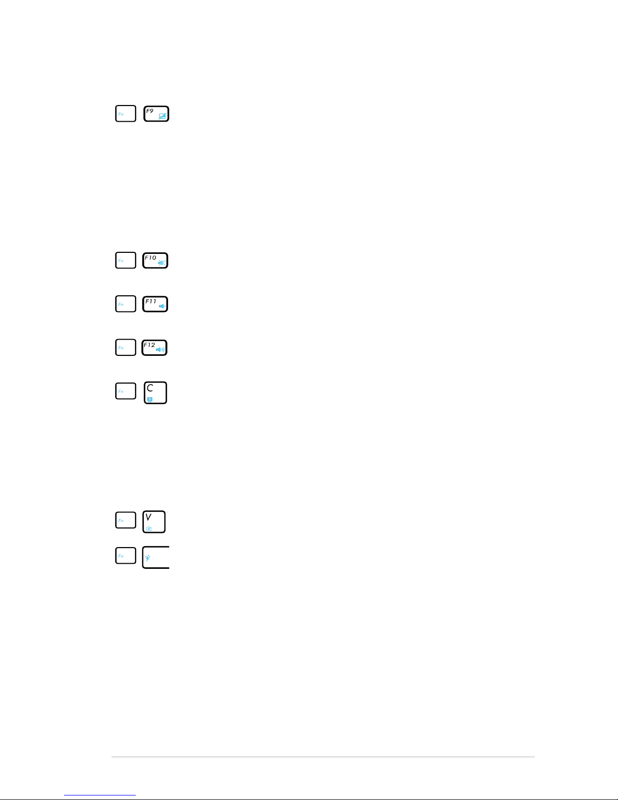
Crossed-out Touchpad (F9): Toggles the built-in
touchpad LOCKED (disabled) and UNLOCKED (enabled).
Locking the touchpad will prevent you from accidentally
moving the pointer while typing and is best used with an
external pointing device such as a mouse. NOTE: Selected
models have an indicator between the touchpad buttons
will light when the touchpad is UNLOCKED (enabled) and
not light when the touchpad is LOCKED (disabled).
Crossed Speaker Icons (F10): Toggles the speakers ON
and OFF (only in Windows OS)
Speaker Down Icon (F11):
Decreases the speaker volume (only in Windows OS)
Speaker Up Icon (F12):
Increases the speaker volume (only in Windows OS)
Fn+C: Toggles “Splendid Video Intelligent Technology”
function ON and OFF. This allows switching between
different display color enhancement modes in order
to improve contrast, brightness, skin tone, and color
saturation for red, green, and blue independently. You
can see the current mode through the onscreen display
(OSD).
Fn+V: Toggles “Life Frame” software application.
Power4Gear Hybrid (Fn+Space Bar): This key toggles
power savings between various power saving modes.
The power saving modes control many aspects of the
Notebook PC to maximize performance versus battery
time. Applying or removing the power adapter will
automatically switch the system between AC mode and
battery mode. You can see the current mode through the
on-screen display (OSD).
Page 40
40
Notebook PC User Manual
Microsoft Windows Keys
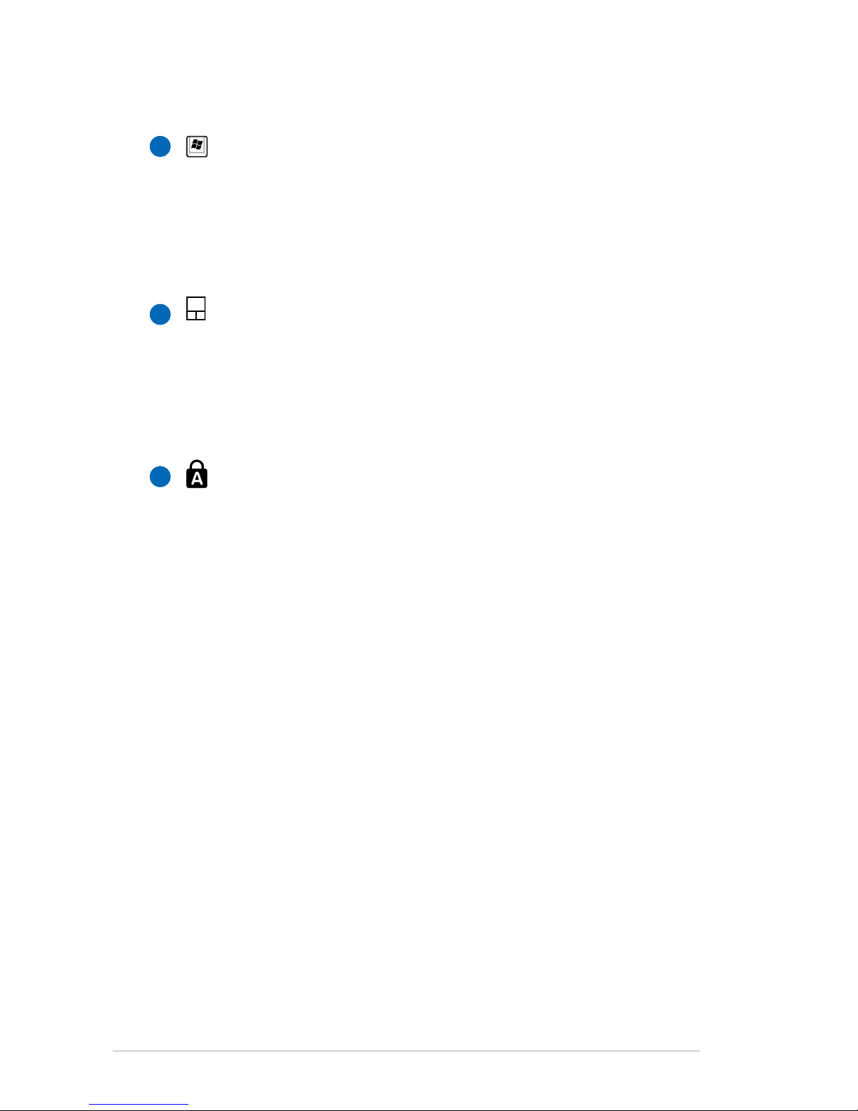
There are two special Windows keys on the keyboard as described
below.
The key with the Windows Logo activates the Start menu
located at the bottom left of the Windows desktop.
The other key, that looks like a Windows menu with
a small pointer, activates the properties menu and is
equivalent to pressing the right mouse button on a
Windows object.
Page 41
Notebook PC User Manual
41
Multimedia Control Keys (on selected models)
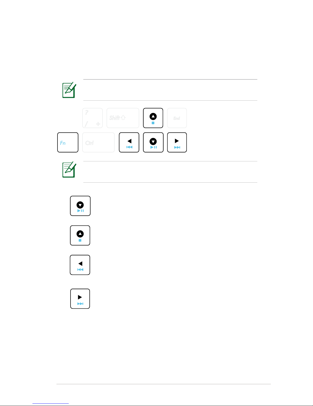
The multimedia control keys allows for convenient controlling of the
multimedia application. The following defines the meaning of each
multimedia control key on the Notebook PC.
Some control key functions may defer depending on Notebook
PC model.
Play/Pause (↓)
Begins or pauses media file playback.
Stop (↑)
Stops media file playback.
Back (←)
During media file playback, goes back to the previous
song / movie chapter.
Forward (→)
During media file playback, skips to the next song /
movie chapter.
Use the [Fn] key in combination with the arrow keys for
multimedia control functions.
Page 42
42
Notebook PC User Manual
Switches and Status Indicators
Switches
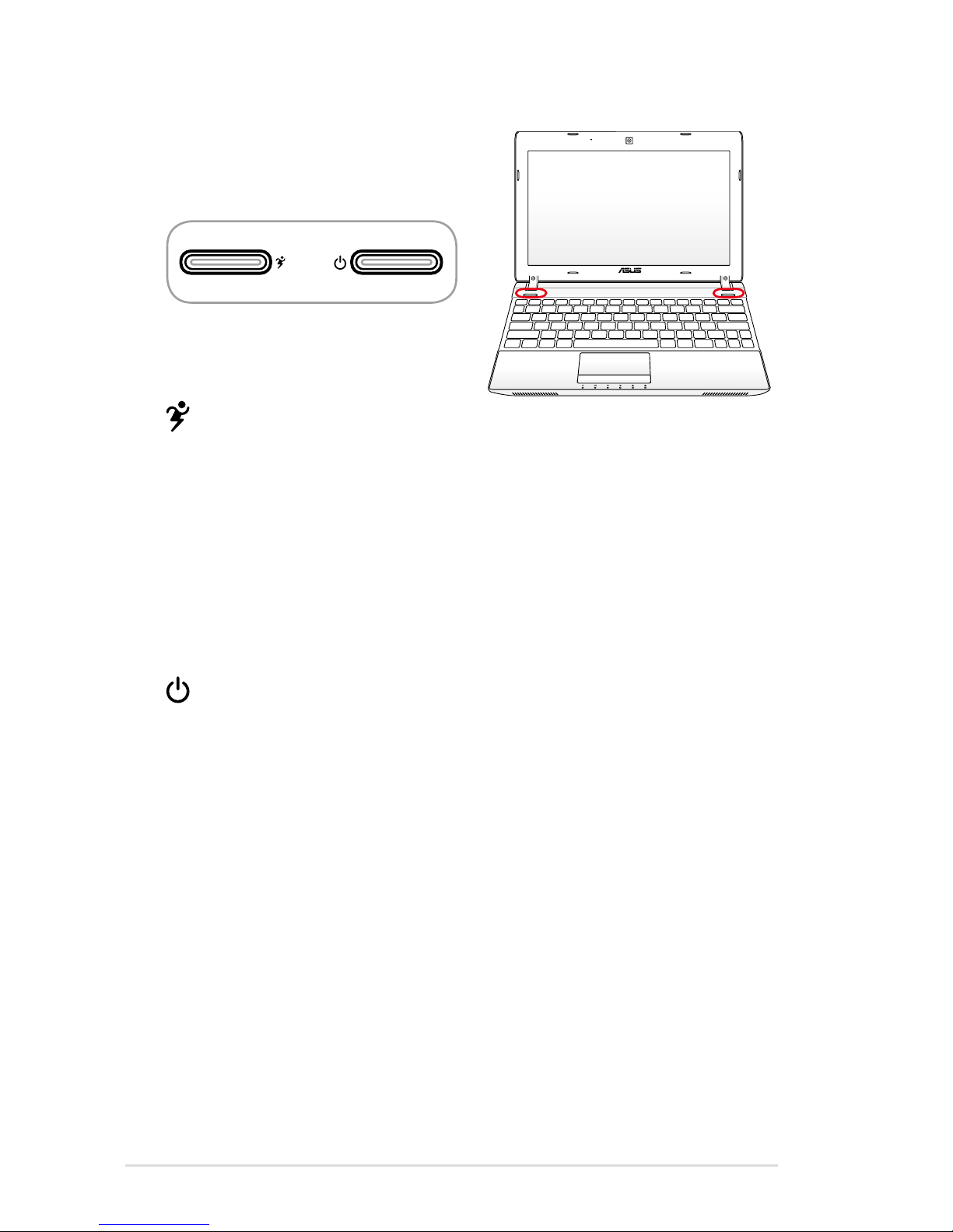
Power4Gear Key (on selected
models)
Under the Windows OS, this key functions as the Power4Gear
Hybrid key. The key toggles power savings between various
power saving modes. The power saving modes control many
aspects of the Notebook PC to maximize performance versus
battery time. Applying or removing the power adapter will
automatically switch the system between AC mode and battery
mode. The selected mode is shown on the display.
Power Switch
The power switch allows powering ON and OFF the Notebook
PC and recovering from STD. Use the switch once to turn ON
and once to turn OFF the Notebook PC. The power switch only
works when the display panel is opened.
Page 43
Notebook PC User Manual
43
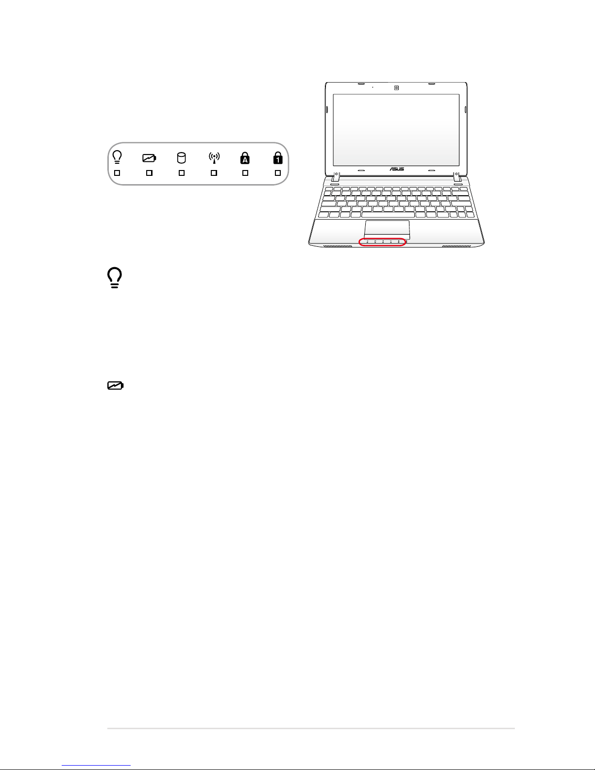
Power Indicator
The power indicator lights when the Notebook PC is turned ON
and blinks slowly when the Notebook PC is in the Suspend-toRAM (Sleep) mode. This indicator is OFF when the Notebook PC
is turned OFF or in the Suspend-to-Disk (Hibernation) mode.
Battery Charge Indicator (dual-color)
The dual-color battery charge indicator shows the status of the
battery’s power as follows:
Green ON: Battery power is between 95% and 100% (with AC
power).
Orange ON: Battery power is less than 95% (with AC power).
Orange Blinking: Battery power is less than 10% (without AC
power).
Off: Battery power is between 10% and 100% (without AC
power).
Status Indicators
Page 44

44
Notebook PC User Manual
Drive Activity Indicator
Indicates that the Notebook PC is accessing one or more storage
device(s) such as the hard disk. The light flashes proportional to
the access time.
Bluetooth / Wireless Indicator
This is only applicable on models with internal Bluetooth (BT)
and built-in wireless LAN. This indicator will light to show that
the Notebook PC’s built-in Bluetooth (BT) function is activated.
When the built-in wireless LAN is enabled, this indicator will also
light. (Windows software settings are necessary.)
Capital Lock Indicator
Indicates that capital lock [Caps Lock] is activated when lighted.
Capital lock allows some of the keyboard letters to type using
capitalized letters (e.g. A, B, C). When the capital lock light is OFF,
the typed letters will be in the lower case form (e.g. a,b,c).
Number Lock Indicator
Indicates that number lock [Num Lk] is activated when lighted.
Number lock allows some of the keyboard letters to act as
numbers for easier numeric data input.
Page 45

4
Chapter 4:
Using the Notebook PC
Page 46
46
Notebook PC User Manual
IMPORTANT! DO NOT use any objects in place of your finger
to operate the touchpad or else damage may occur to the
touchpad’s surface.
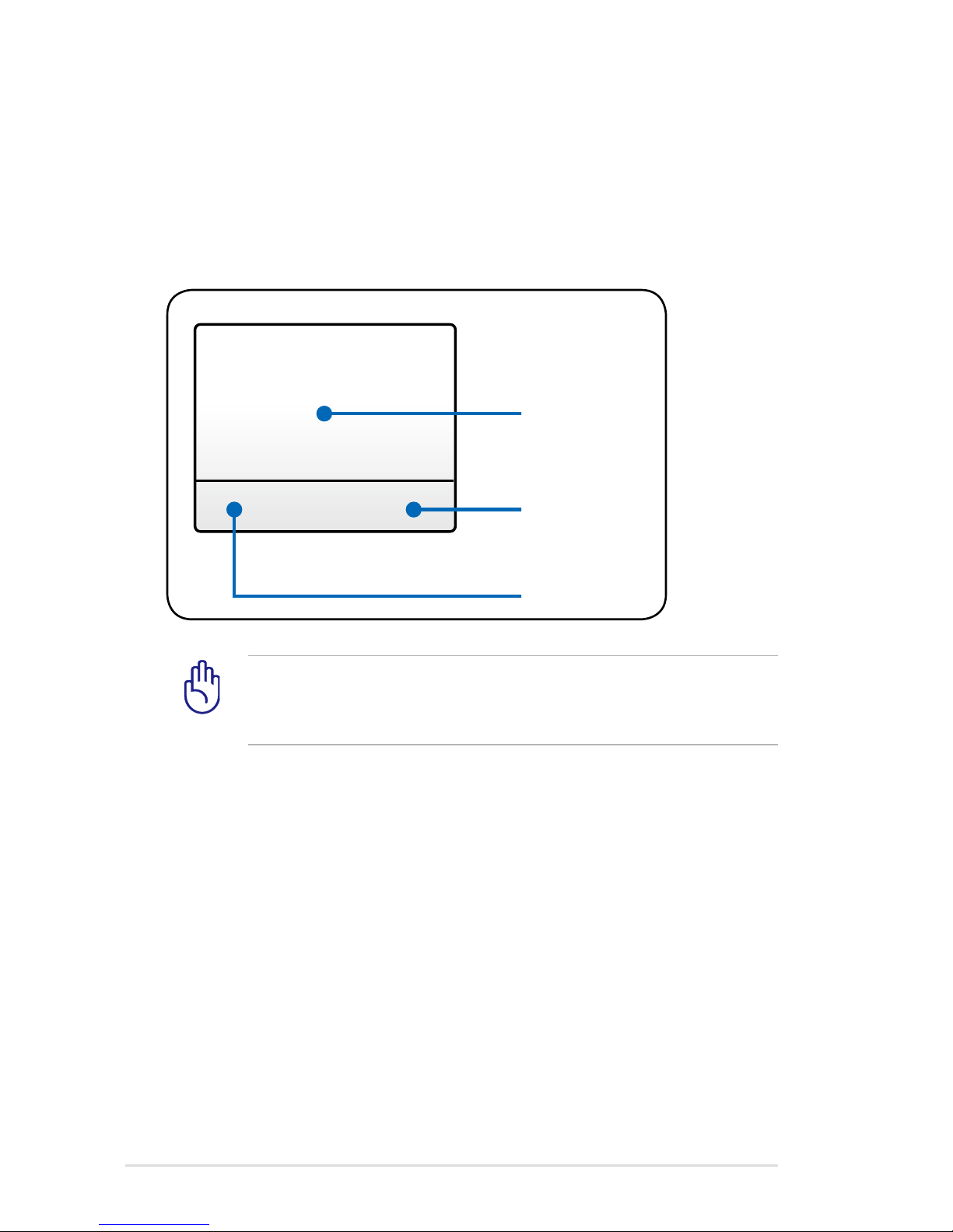
Pointing Device
The Notebook PC’s integrated touchpad pointing device is fully
compatible with all two/three-button and scrolling knob PS/2 mice.
The touchpad is pressure sensitive and contains no moving parts;
therefore, mechanical failures can be avoided. A device driver is still
required for working with some application software.
Pointer Movement
Right Click
Left Click
Page 47
Notebook PC User Manual
47
Using the Touchpad
The touchpad allows you to use your fingers to move the pointer
around or select onscreen items instead of using a standard
mouse. To use the touchpad, lightly press or tap your finger on the
touchpad.
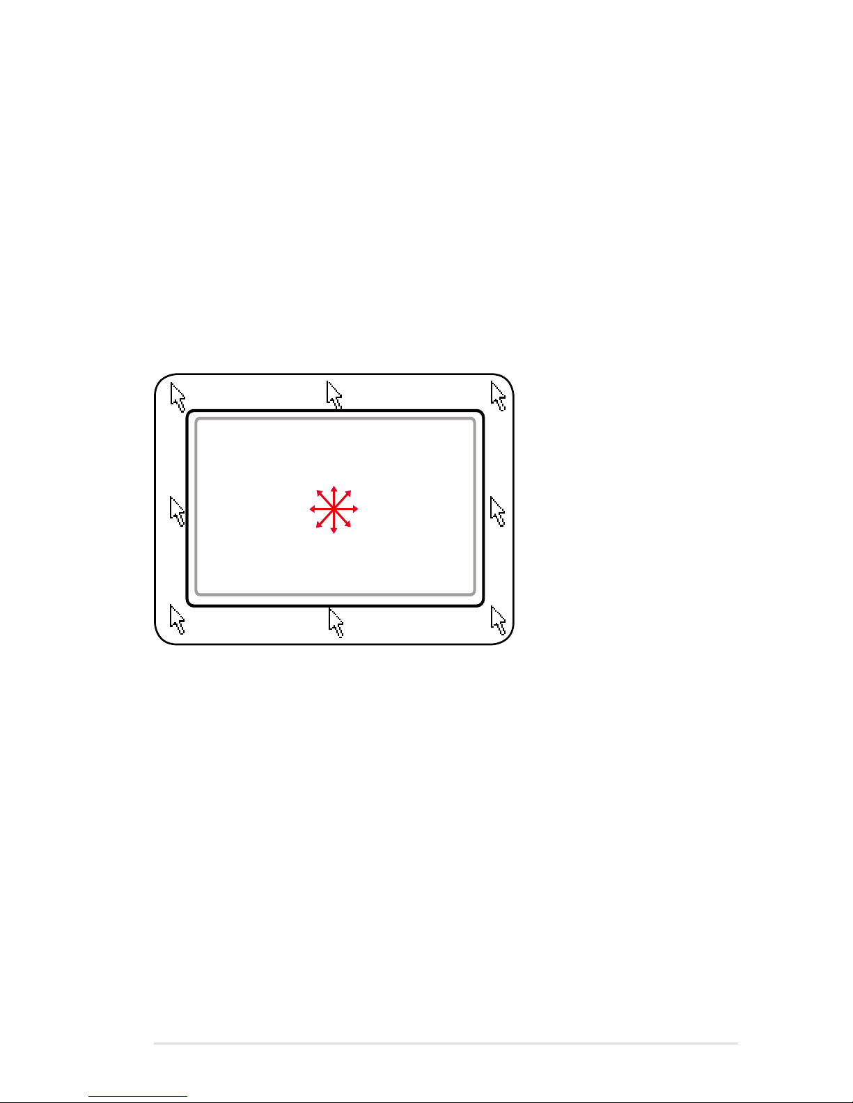
Moving The Pointer
Place your finger in the center of the touchpad and slide in a
direction to move the pointer.
Slide finger forward
Slide finger
left
Slide finger
backward
Slide finger
right
Page 48
48
Notebook PC User Manual
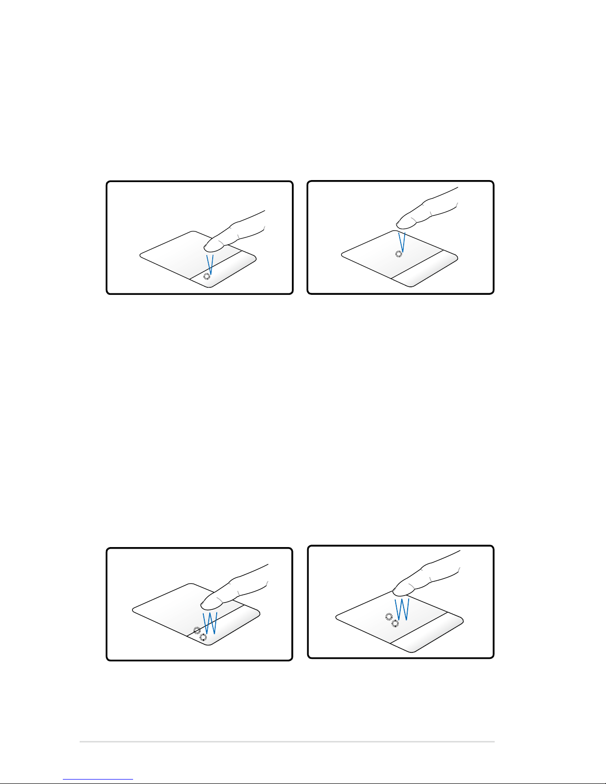
Press the left pointer button
and release.
Lightly but rapidly strike the
touchpad.
Touchpad Usage Illustrations
Clicking/Tapping - With the pointer over an item, press the left button
or use your fingertip to touch the touchpad lightly, keeping your finger
on the touchpad until the item is selected. The selected item will change
color. The following two examples produce the same results.
Double-clicking/Double-tapping - These actions allows you to launch
your selected program. Move your finger over the program that you
want to launch, press the left button or tap the pad twice in rapid
succession, and the system launches your selected program. If the
interval between the clicks or taps is too long, the operation will not
be executed. You can set the double-click speed using the Windows
Control Panel “Mouse.” The following two examples produce the same
results.
Press the left button twice
and release.
Lightly but rapidly strike the
touchpad twice.
Clicking
DoubleClicking
Tapping
DoubleTapping
Page 49
Notebook PC User Manual
49
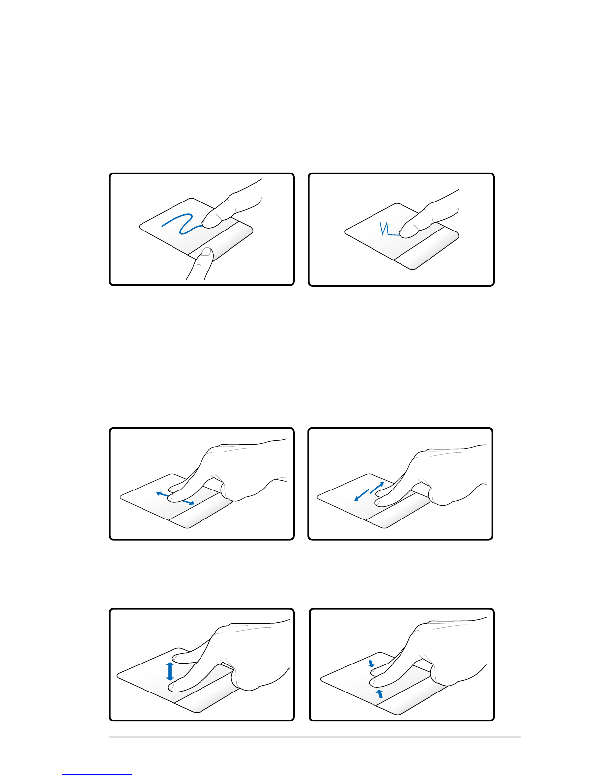
Dragging - Dragging refers to moving an item to another location.
Move your finger over an item, while simultaneously pressing the left
button, move the item to your desired location, then release the left
button. You can also double-tap and hold the item while dragging it
with your finger. The following illustrations produce the same results.
Hold left button and slide
finger on touchpad.
Lightly strike the touchpad
twice, sliding finger on touchpad
during second strike.
Dragging-Clicking
Two-finger scrolling - Use two fingertips to slide up/down/left/
right on the touchpad to scroll a window up/down/left/right. If your
display window includes several sub-windows, move the pointer on
that pane before scrolling.
Dragging-Tapping
Scrolling vertically
Scrolling
horizontally
Two-finger zooming in/out - Moving two fingertips apart or
together on the touchpad to zoom in or zoom out. This is convenient
when viewing photos or reading documents.
Zoom in
Zoom out
Page 50
50
Notebook PC User Manual
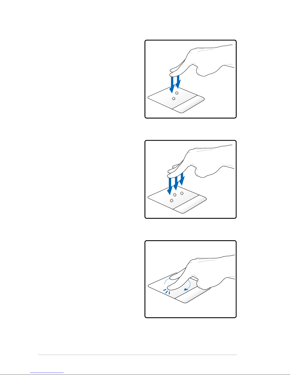
Two-finger tapping - Use two
fingers to tap the touchpad. This
action simulates the click on the
scroll wheel of a mouse.
Three-finger tapping -
Use three fingers to tap the
touchpad. This action mimics the
right-click function of a mouse.
Two-finger rotating- Fix one
fingertip on the touchpad and
make an arc with the other
to rotate the photo or the
document you are viewing.
You can make a clockwise or
counterclockwise rotation based
on your needs.
Page 51
Notebook PC User Manual
51
The touchpad responds to movement not to force. There is no need
to tap the surface too hard. Tapping too hard does not increase
the responsiveness of the touchpad. The touchpad responds best
to light pressure.
Caring for the Touchpad
The touchpad is pressure sensitive. If not properly cared for, it can be
easily damaged. Take note of the following precautions.
• Ensure the touchpad does not come into contact with dirt, liquids or
grease.
• Do not touch the touchpad if your ngers are dirty or wet.
• Do not rest heavy objects on the touchpad or the touchpad
buttons.
• Do not scratch the touchpad with your nger nails or any hard
objects.
Automatic Touchpad Disabling
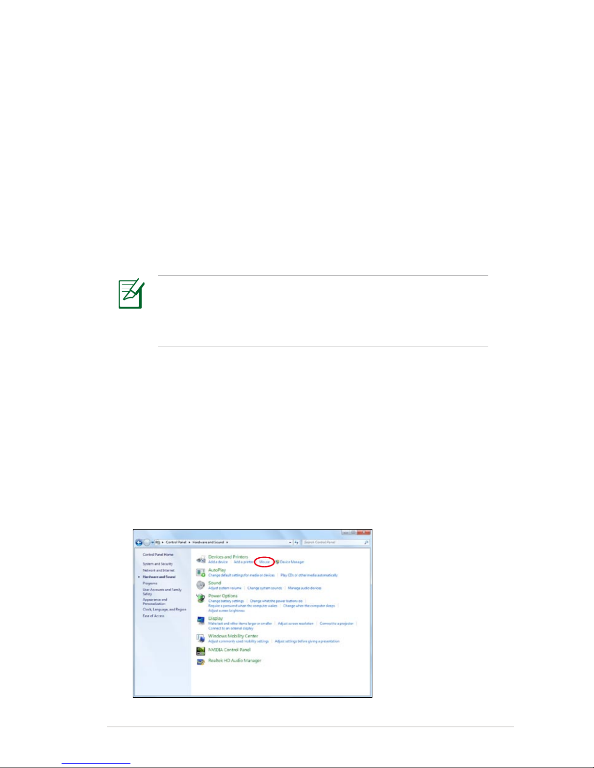
Windows can automatically disable the Notebook PC’s touchpad
when an external USB mouse is attached.
This feature is normally OFF, to turn ON this feature:
1. Select the option in Windows Control Panel > Hardware and
Sound > Mouse.
Page 52
52
Notebook PC User Manual
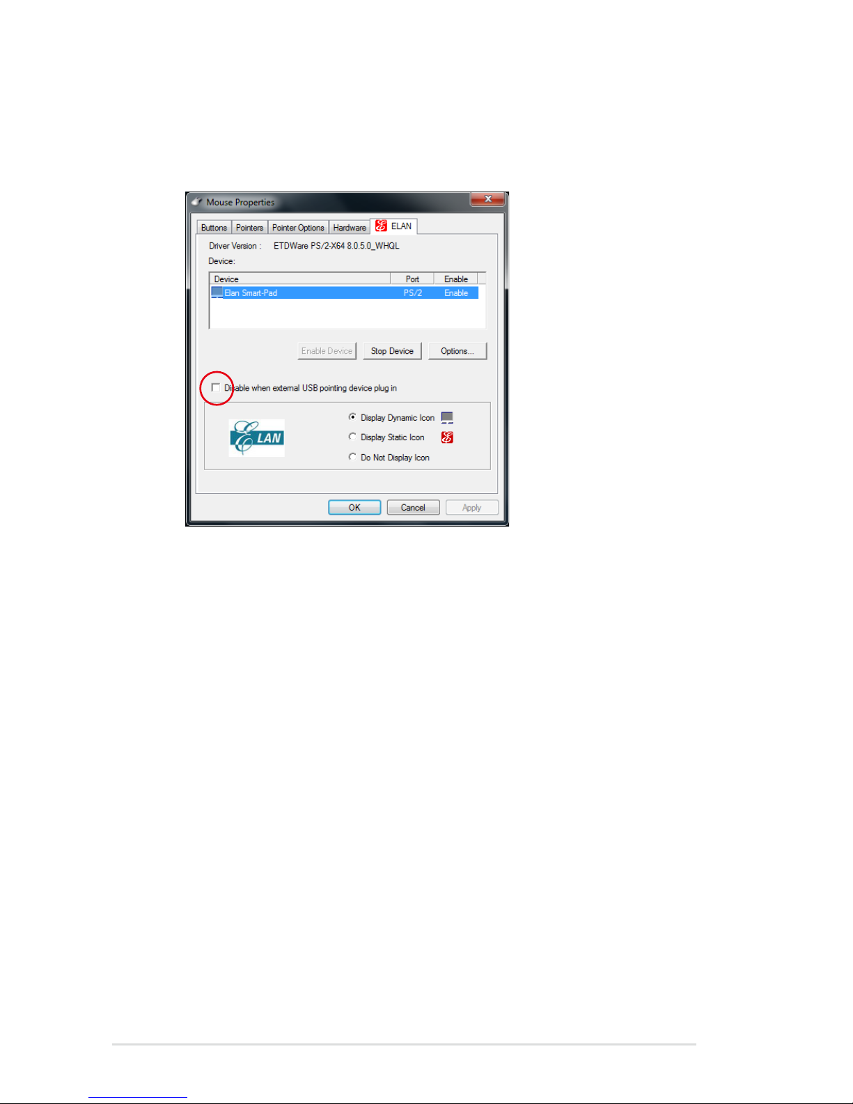
2. Click ELAN on the top and click Disable when external USB
pointing device plug in check box.
3. Click OK to finish the configuration.
Page 53
Notebook PC User Manual
53
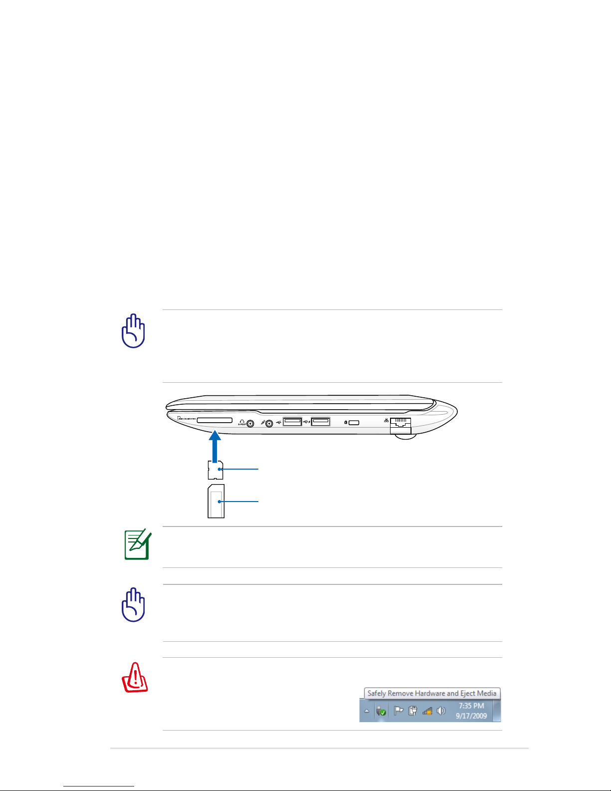
Flash Memory Card Reader
Normally a memory card reader must be purchased separately in
order to use memory cards from devices such as digital cameras,
MP3 players, mobile phones, and PDAs. This Notebook PC has a
single built-in memory card reader that can use many flash memory
cards as shown in the example below. The built-in memory card
reader is not only convenient, but also faster than most other
forms of memory card readers because it utilizes the internal highbandwidth PCI bus.
WARNING! To prevent data loss, use “Safely Remove Hardware
and Eject Media” in the Windows
notification area before removing
the flash memory card.
IMPORTANT! Flash memory card compatibility varies depending
on Notebook PC model and flash memory card specifications.
Flash memory card specifications constantly change so
compatibility may change without warning.
IMPORTANT! Never remove cards while or immediately after
reading, copying, formatting, or deleting data on the card or else
data loss may occur.
The actual location of the Flash Memory Slot differs by models.
Refer to the previous chapter to locate the Flash Memory Slot.
Storage Devices
Storage devices allow the Notebook PC to read or write documents,
pictures, and other files to various data storage devices.
MS / MS Pro
SD / MMC
Page 54
54
Notebook PC User Manual
Installing a Memory Card:
Removing a Memory Card:
3
(This is only an example.)
3
(This is only an example.)
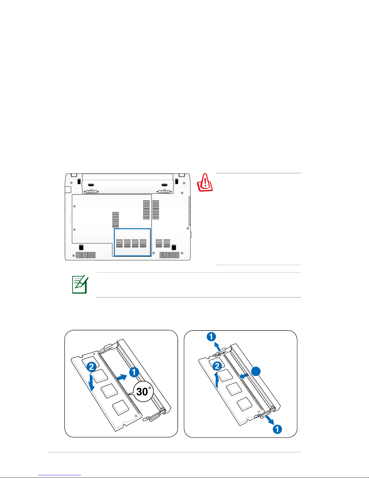
Memory (RAM)
Additional memory will increase application performance by
decreasing hard disk access. Visit an authorized service center or
retailer for information on memory upgrades for your Notebook PC.
Only purchase expansion modules from authorized retailers of this
Notebook PC to ensure maximum compatibility and reliability.
The BIOS automatically detects the amount of memory in the
system and configures CMOS accordingly during the POST (PowerOn-Self-Test) process. There is no hardware or software (including
BIOS) setup required after the memory is installed.
WARNING! Disconnect all
the connected peripherals,
any telephone or
telecommunication lines
and power connector
(such as external power
supply, battery pack,
etc.) before installing or
removing a memory.
The actual location of the memory differs by models. Refer to the
previous chapter to locate the memory.
Page 55

Notebook PC User Manual
55
The built-in network cannot be installed later as an upgrade.
After purchase, network can be installed as an expansion card.
Connections
Network Connection
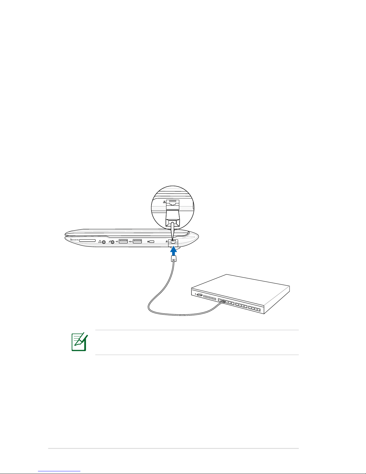
Connect a network cable, with RJ-45 connectors on each end, to the
modem/network port on the Notebook PC and the other end to a
hub or switch. For 100 BASE-TX / 1000 BASE-T speeds, your network
cable must be category 5 or better (not category 3) with twisted-pair
wiring. If you plan on running the interface at 100/1000Mbps, it must
be connected to a 100 BASE-TX / 1000 BASE-T hub (not a BASE-T4
hub). For 10Base-T, use category 3, 4, or 5 twisted-pair wiring. 10/100
Mbps Full-Duplex is supported on this Notebook PC but requires
connection to a network switching hub with “duplex” enabled. The
software default is to use the fastest setting so no user-intervention
is required.
1000BASE-T (or Gigabit) is only supported on selected models.
Page 56
56
Notebook PC User Manual
Twisted-Pair Cable
The cable used to connect the Ethernet card to a host (generally
a Hub or Switch) is called a straight-through Twisted Pair Ethernet
(TPE). The end connectors are called RJ-45 connectors, which are
not compatible with RJ-11 telephone connectors. If connecting two
computers together without a hub in between, a crossover LAN
cable is required (Fast-Ethernet model). (Gigabit models support
auto-crossover so a crossover LAN cable is optional.)
Example of the Notebook PC connected to a Network Hub or Switch
for use with the built-in Ethernet controller.
Network cable with
RJ-45 connectors
Network Hub or Switch
The actual location of the LAN port differs by models. Refer to
the previous chapter to locate the LAN port.
Page 57

Notebook PC User Manual
57
Wireless LAN Connection (on selected models)
The optional built-in wireless LAN is a compact easy-to-use wireless
Ethernet adapter. Implementing the IEEE 802.11 standard for
wireless LAN (WLAN), the optional built-in wireless LAN is capable of
fast data transmission rates using Direct Sequence Spread Spectrum
(DSSS) and Orthogonal Frequency Division Multiplexing (OFDM)
technologies on 2.4GHz/5GHz frequencies. The optional built-in
wireless LAN is backward compatible with the earlier IEEE 802.11
standards allowing seamless interfacing of wireless LAN standards.
The optional built-in wireless LAN is a client adapter that supports
Infrastructure and Ad-hoc modes giving you flexibility on your
existing or future wireless network configurations for distances up to
40 meters between the client and the access point.
To provide efficient security to your wireless communication, the
optional built-in wireless LAN comes with a 64-bit/128-bit Wired
Equivalent Privacy (WEP) encryption and Wi-Fi Protected Access
(WPA) features.
For security concerns, DO NOT connect to the unsecured
network; otherwise, the information transmission without
encryption might be visible to others.
Page 58
58
Notebook PC User Manual
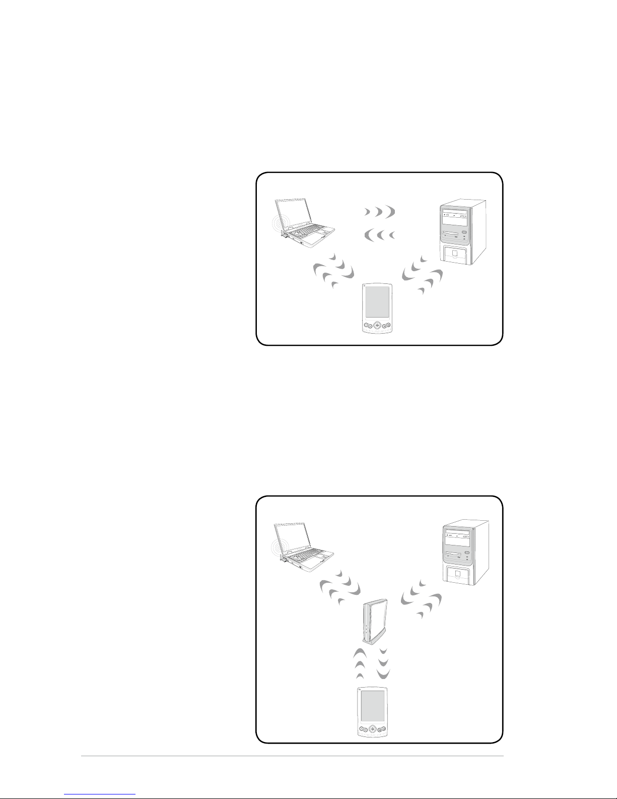
Ad-hoc mode
The Ad-hoc mode allows the Notebook PC to connect to another
wireless device. No access point (AP) is required in this wireless
environment.
(All devices must install
optional 802.11 wireless
LAN adapters.)
Desktop PC
PDA
Notebook PC
Infrastructure mode
The Infrastructure mode allows the Notebook PC and other wireless
devices to join a wireless network created by an Access Point (AP)
(sold separately) that provides a central link for wireless clients to
communicate with each other or with a wired network.
(All devices must install
optional 802.11 wireless
LAN adapters.)
Access Point
Desktop PC
PDA
Notebook PC
Page 59
Notebook PC User Manual
59
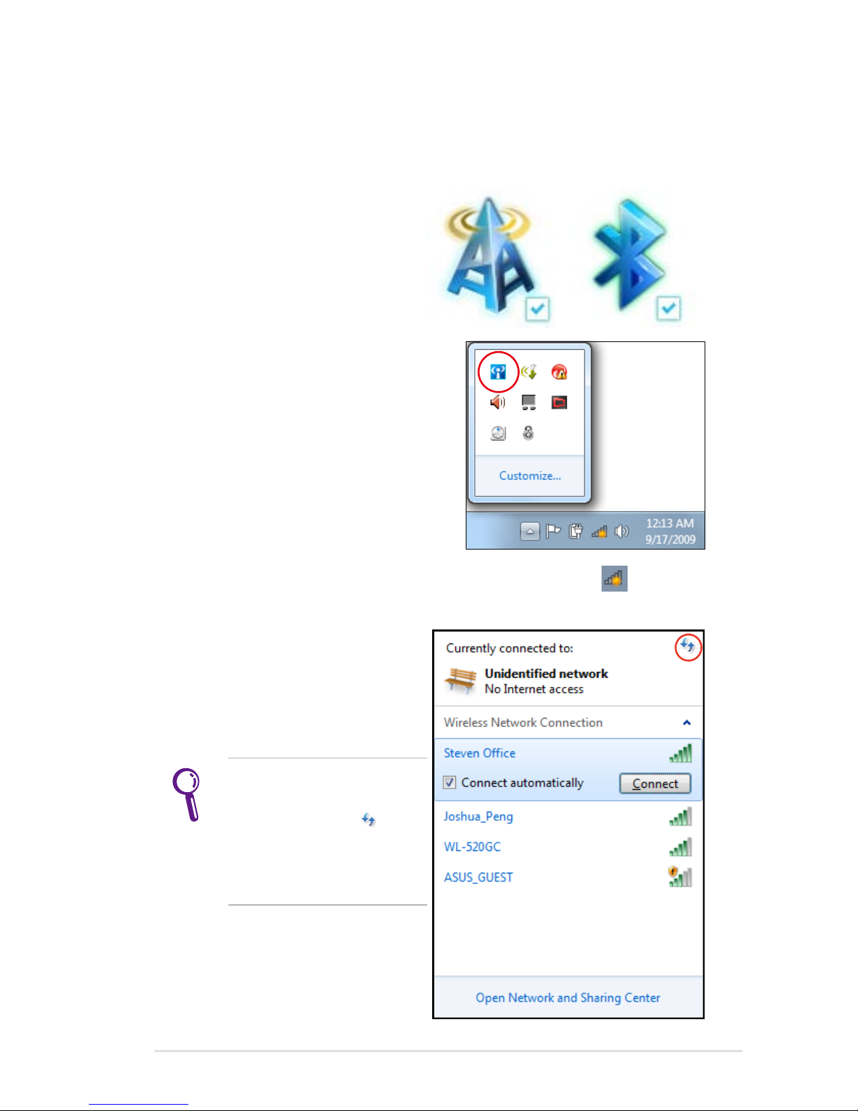
Windows Wireless Network Connection
Connecting to a network
1. Switch ON the Wireless function if necessary for your model (see
switches in Chapter 3).
2. Press [FN+F2] repeatedly
until wireless LAN icon and
Bluetooth icon are shown.
Or double click the Wireless
Console icon in Windows
notification area and select the
wireless LAN icon.
3. Click the wireless network icon with an orange star in the
Windows® Notification area.
4. Select the wireless access
point you want to connect
to from the list and click
Connect to build the
connection.
If you cannot find the
desired access point, click
the Refresh icon on
the upper right corner to
refresh and search in the
list again.
Page 60
60
Notebook PC User Manual
5. When connecting, you may have to enter a password.
6. After a connection has been established, the connection is
shown on the list.
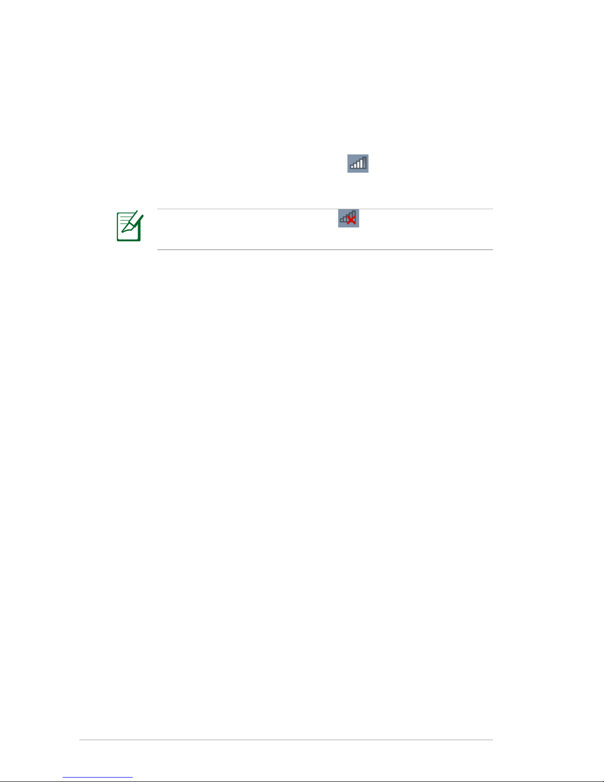
7. You can see the wireless network icon in the Notification
area.
The crossed wireless network icon appears when you press
<Fn> + <F2> to disable the WLAN function.
Page 61

Notebook PC User Manual
61
Bluetooth Wireless Connection
(on selected models)
Notebook PCs with Bluetooth technology eliminates the need for
cables for connecting Bluetooth-enabled devices. Examples of
Bluetooth-enabled devices may be Notebook PCs, Desktop PCs,
mobile phones, and PDAs.
If your Notebook PC did not come with built-in Bluetooth, you
need to connect a USB or ExpressCard Bluetooth module in
order to use Bluetooth.
Bluetooth-enabled mobile phones
You can wireless connect to your mobile phone. Depending on
your mobile phone’s capabilities, you can transfer phone book
data, photos, sound files, etc. or use it as a modem to connect to the
Internet. You may also use it for SMS messaging.
Bluetooth-enabled computers or PDAs
You can wireless connect to another computer or PDA and exchange
files, share peripherals, or share Internet or network connections.
You may also make use of Bluetooth-enabled wireless keyboard or
mouse.
Turning ON and Launching Bluetooth Utility
This process can be used to add most Bluetooth devices.
1. Switch ON the Wireless function if necessary for your model (see
switches in Chapter 3).
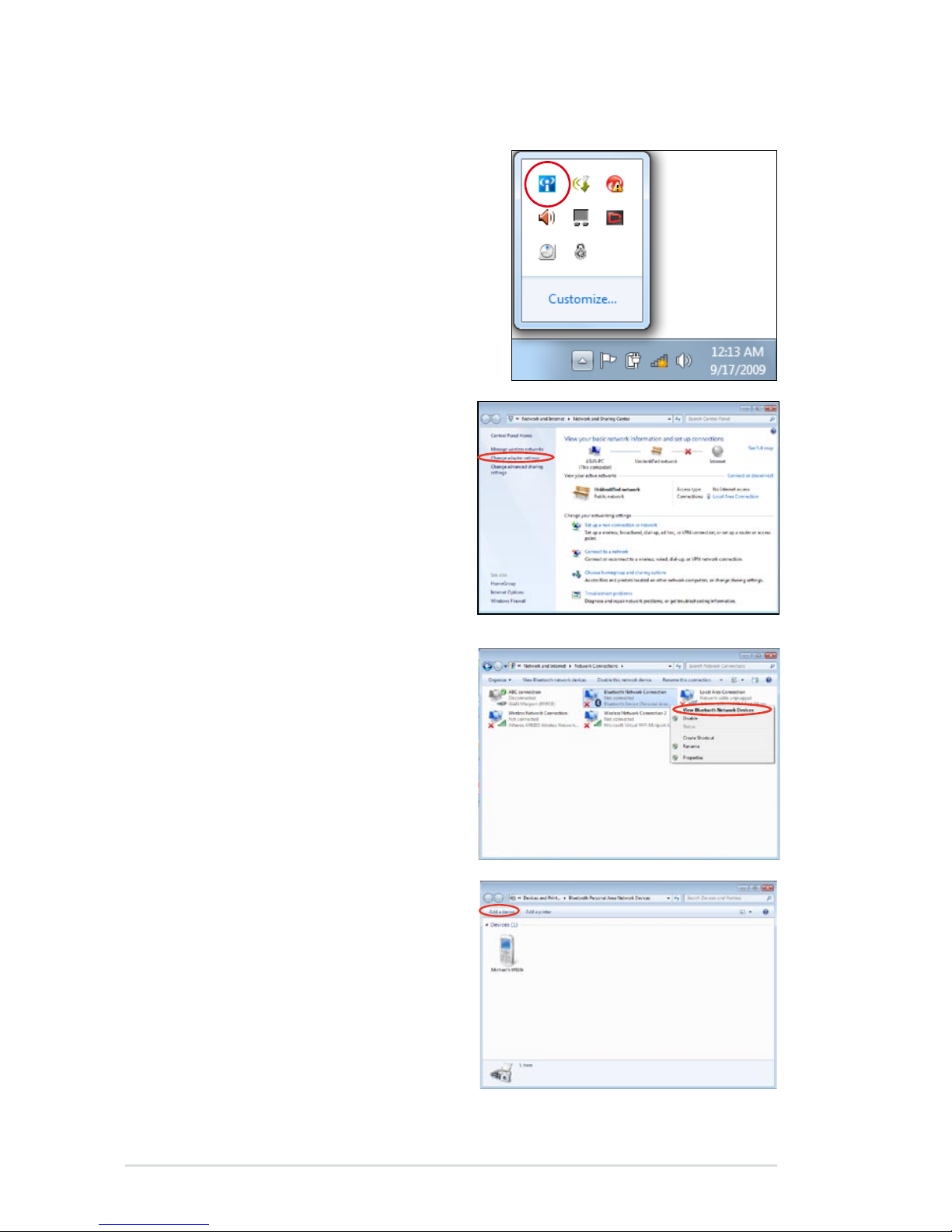
2. Press [FN+F2] repeatedly
until wireless LAN icon and
bluetooth icon are shown.
Page 62
62
Notebook PC User Manual
Or double click the Wireless
Console icon in the Windows
notification area and select the
Bluetooth icon.
3. From Control Panel, go
to Network and Internet
> Network and Sharing
Center and then click
Change adapter settings in
the left blue pane.
4. Right-click Bluetooth
Network Connection and
select View Bluetooth
Network Devices.
5. Click Add a device to look for
new devices.
Page 63
Notebook PC User Manual
63
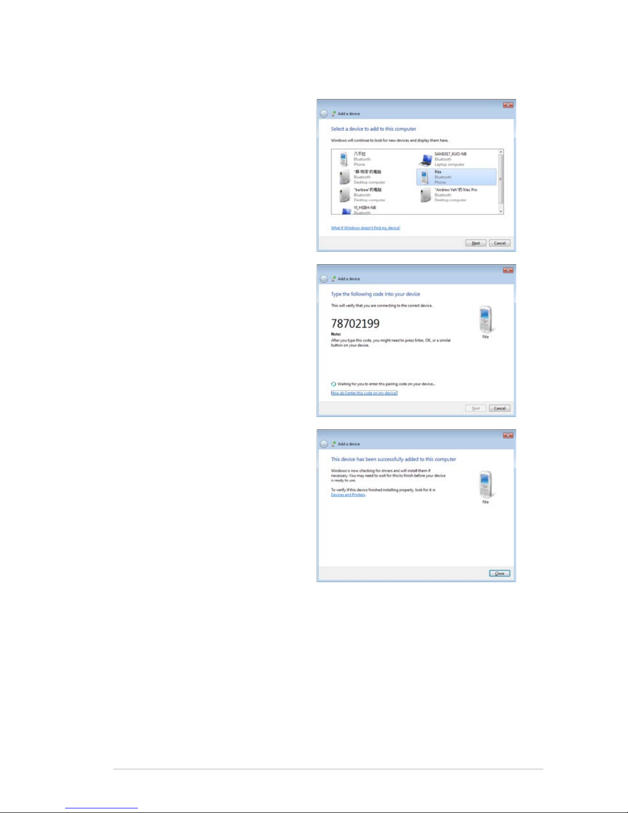
6. Select a Bluetooth-enabled
device from the list and click
Next.
7. Enter the Bluetooth security
code into your device and
start pairing.
8. The paired relationship is
successfully built. Click Close
to finish the setting.
Page 64
64
Notebook PC User Manual
USB Charger+
USB Charger+ helps charge your USB devices compatible with
Battery Charging Version 1.1 (BC 1.1) specifications whether your
Notebook PC is powered on or off. You can decide and set the
battery threshold for stopping charging according to your needs.
With Adapter
USB Charger+ is always available on the designated USB port when
your Notebook PC is connected with the adapter.
Without Adapter
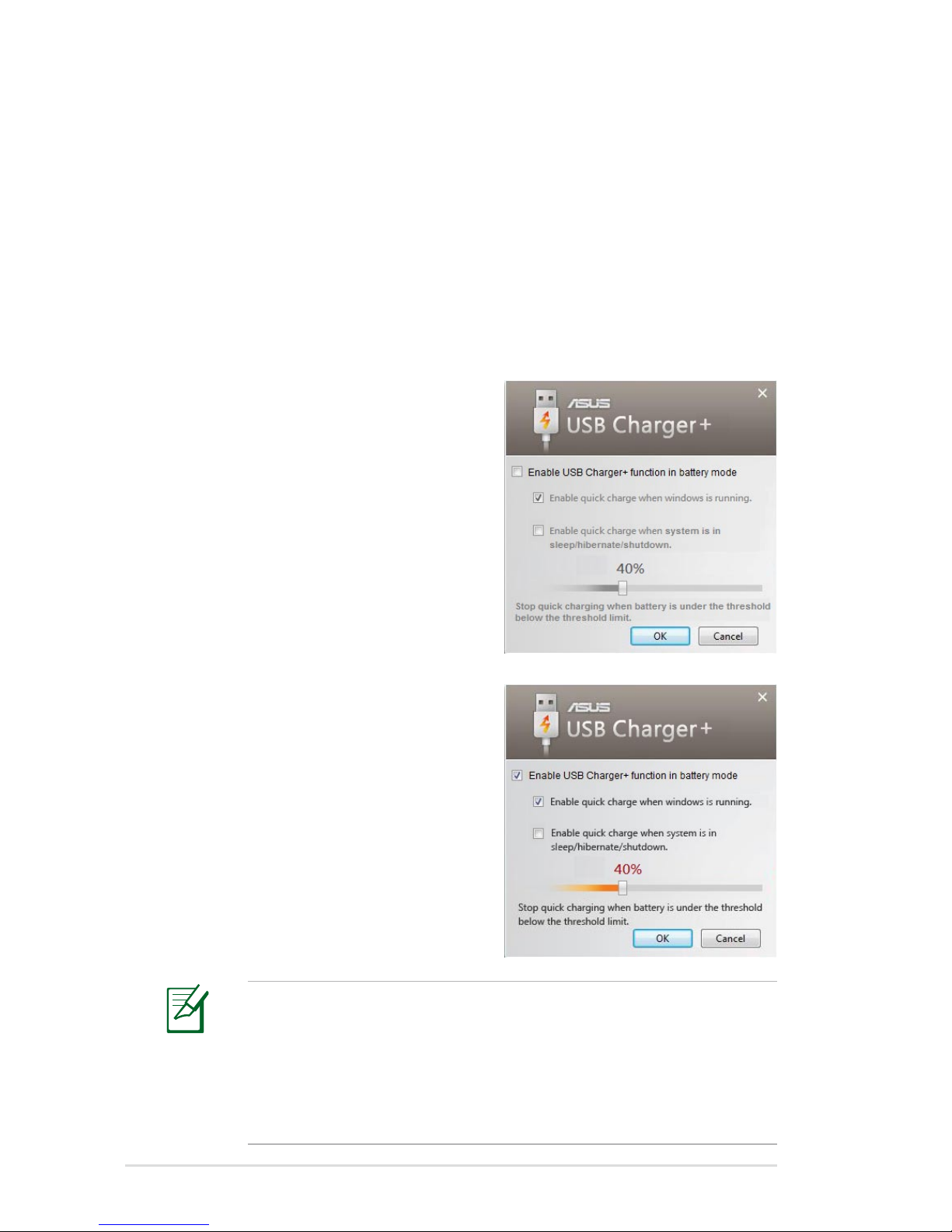
To enable the USB Charger+
1. Click the USB Charger+ icon in
the notification area and select
Settings.
2. Click Enable USB Charger
function in battery mode.
3. According to your needs, click
to enable quick charge when
the Notebook PC is powered
ON or in sleep/hibernation/
shutdown.
4. Move the slider to set the
battery charge threshold
to stop the USB Charger+
function.
• The Notebook PC stops charging your connected USB device
when the battery charge drops below your set threshold.
• The USB port that supports USB Charger+ does not support
USB device wake up function.
• If your connected device is overheated, smoking, or has
abnormal odors, remove the device immediately.
Page 65
Notebook PC User Manual
65
Instant On
Zero-wait system restarting gets you immediately back to work and
play with saved system status. After activating it, the SHUT DOWN
button in the Start Menu will be changed to SLEEP so you could
enjoy fast resume to your last working state.
During WINDOWS UPDATE, the “Instant On” feature will be
automatically disabled so the SHUT DOWN button in the Start
Menu will not be changed to the SLEEP function before all
updates are completed.When Instant On function is enabled,
“Wake on USB/LAN“ function will be disabled.
When Instant On function is enabled, “Wake on USB/LAN“
function will be disabled.
Page 66

66
Notebook PC User Manual
Page 67

A
Appendix
Page 68

A-2
Notebook PC User Manual
Operating System and Software
This Notebook PC may offer (depending on territory) its customers
the choice of a pre-installed Microsoft Windows operating system.
The choices and languages will depend on the territory. The levels
of hardware and software support may vary depending on the
installed operating system. The stability and compatibility of other
operating systems cannot be guaranteed.
Support Software
This Notebook PC comes with a support disc that provides BIOS,
drivers and applications to enable hardware features, extend
functionality, help manage your Notebook PC, or add functionality
not provided by the native operating system. If updates or
replacement of the support disc is necessary, contact your dealer for
web sites to download individual software drivers and utilities.
The support disc contains all drivers, utilities and software for all
popular operating systems including those that have been preinstalled. The support disc does not include the operating system
itself. The support disc is necessary even if your Notebook PC came
pre-configured in order to provide additional software not included
as part of the factory pre-install.
A recovery disc is optional and includes an image of the original
operating system installed on the hard drive at the factory. The
recovery disc provides a comprehensive recovery solution that
quickly restores the Notebook PC’s operating system to its original
working state provided that your hard disk drive is in good working
order. Contact your retailer if you require such a solution.
Some of the Notebook PC’s components and features may not
work until the device drivers and utilities are installed.
Page 69
Notebook PC User Manual
A-3
System BIOS Settings
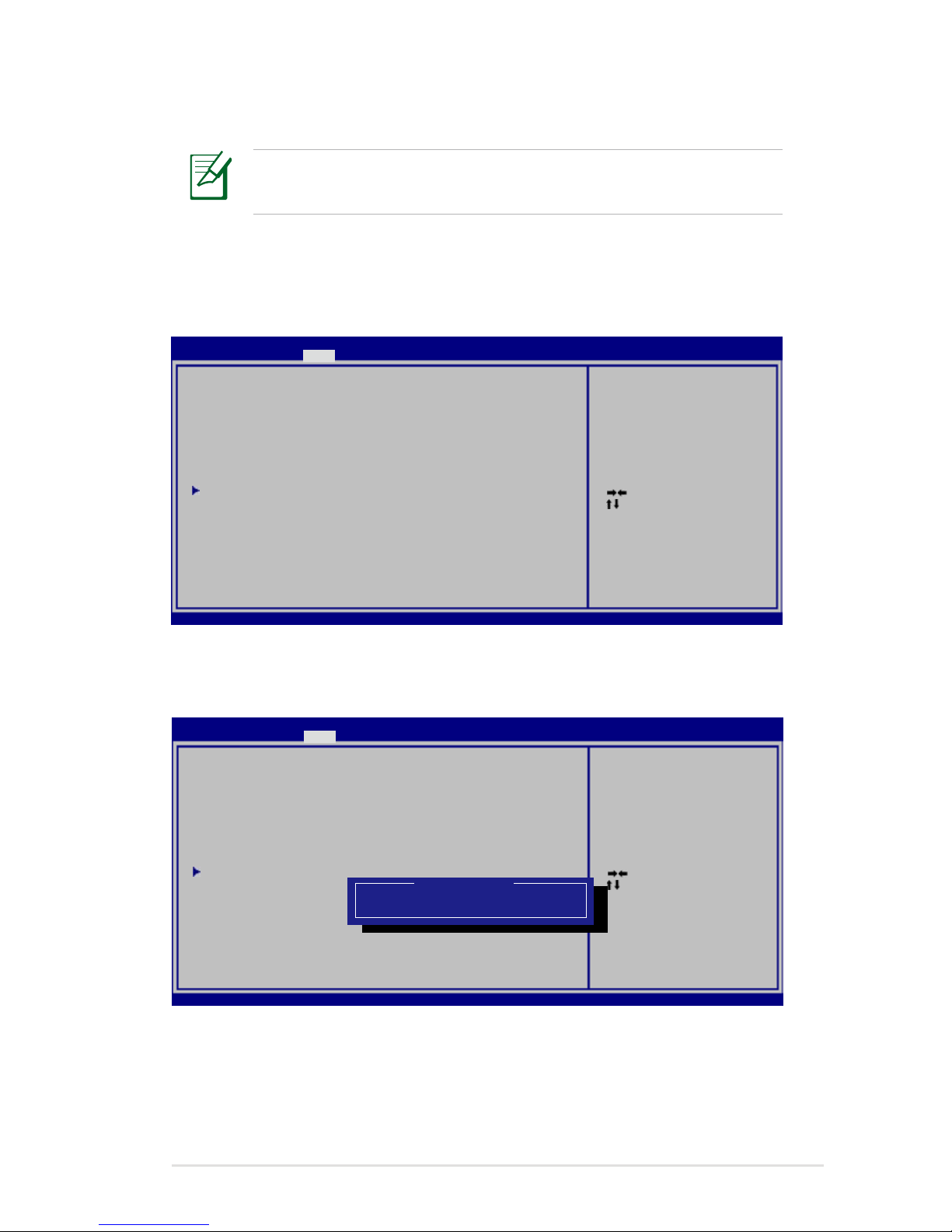
Boot Device
1. On the Boot screen, select Boot Option #1.
: Se le ct S cr ee n
: Se lec t It em
En ter : Se le ct
+/ —: Ch ang e Op t.
F1 : Ge ner al H el p
F9 : Op tim iz ed D ef au lt s
F1 0: Sav e E SC : E xi t
Ve rsi on 2 .0 1. 12 04 . Co py ri gh t (C ) 20 10 A me ri can Megatrends, Inc.
A pt io S et up U tility - Copyright (C) 20 10 Ame ri ca n Me ga tr en ds , In c.
M ai n A dv an ce dMa in A dv an ce d B oo t S ec ur it y S av e & Exit
Bo ot C on fi gu ra ti on
UE FI B oo t [D isa bl ed ]
PX E RO M [D isa bl ed ]
Bo ot O pt io n Pr io ri ti es
Bo ot O pt io n #1 [P 0: S T9 64 04 23 AS . .. ]
Ha rd D ri ve B BS P ri or it ie s
Ad d Ne w Bo ot O pt io n
D ele te B oo t Op ti on
Se t t he s ys te m bo ot o rd er .
2. Press [Enter] and select a device as the Boot Option #1.
: Se le ct S cr ee n
: Se lec t It em
En ter : Se le ct
+/ —: Ch ang e Op t.
F1 : Ge ner al H el p
F9 : Op tim iz ed D ef au lt s
F1 0: Sav e E SC : E xi t
Ve rsi on 2 .0 1. 12 04 . Co py ri gh t (C ) 20 10 A me ri can Megatrends, Inc.
A pt io S et up U tility - Copyright (C) 20 10 Ame ri ca n Me ga tr en ds , In c.
M ai n A dv an ce dMa in A dv an ce d B oo t S ec ur it y S av e & Exit
Bo ot C on fi gu ra ti on
UE FI B oo t [D isa bl ed ]
PX E RO M [D isa bl ed ]
Bo ot O pt io n Pr io ri ti es
Bo ot O pt io n #1 [P 0: S T9 64 04 23 AS . .. ]
Ha rd D ri ve B BS P ri or it ie s
Ad d Ne w Bo ot O pt io n
D ele te B oo t Op ti on
Se t t he s ys te m bo ot o rd er .
Bo ot Op ti on # 1
P0 : ST 96 40 42 3A S
Di sab le d
The BIOS screens in this section are for reference only. The actual
screens may differ by models and territories.
Page 70
A-4
Notebook PC User Manual
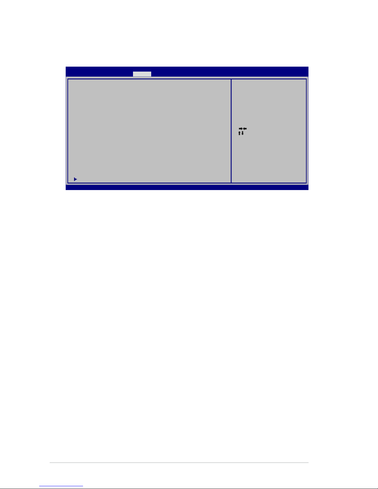
Security Setting
To set the password:
1. On the Security screen, select Setup Administrator Password
or User Password.
2. Type in a password and press [Enter].
3. Re-type to confirm the password and press [Enter].
4. Password is then set.
To clear the password:
1. On the Security screen, select Setup Administrator Password
or User Password.
2. Enter the current password and press [Enter].
3. Leave the Create New Password field blank and press [Enter].
4. Leave the Confirm New Password field blank and press [Enter].
5. Password is then cleared.
: Se le ct S cr ee n
: Se lec t It em
En ter : Se le ct
+/ —: Ch ang e Op t.
F1 : Ge ner al H el p
F2 : Pr evi ou s Va lu es
F9 : Op tim iz ed D ef au lt s
F1 0: Sav e E SC : E xi t
Ve rsi on 2 .0 1. 12 04 . Co py ri gh t (C ) 20 10 A me ri can Megatrends, Inc.
A pt io S et up U tility - Copyright (C) 20 10 Ame ri ca n Me ga tr en ds , In c.
M ai n A dv an ce d B ootMa in A dv an ce d B oo t S ec ur it y S av e & Exit
Pa ss wo rd D es cr ip ti on
If O NL Y th e Ad mi ni st ra to r’ s pa ss wo rd i s set,
th en t hi s on ly l im it s ac ce ss t o Se tu p an d is
on ly a sk ed f or w he n en te ri ng S et up .
If O NL Y th e us er ’s p as sw or d is s et , th en this
is a p ow er o n pa ss wo rd a nd m us t be e nt er ed to
bo ot o r en te r Se tu p. I n Se tu p, t he U se r will
ha ve A dm in is tr at or r ig ht s.
A dm in is tr at or P as sw or d NO T I NS TA LL ED
U se r Pa ss wo rd S ta tu s NO T I NS TA LL ED
S et up a dm in is tr at or p as sw or d
U se r Pa ss wo rd
H DD U se r Pa ss wo rd S ta tu s : NOT INSTALLED
S et M as te r Pa ss wo rd
S et U se r Pa ss wo rd
I /O In te rf ac e Se cu ri ty
Se t t he s ys te m bo ot o rd er .
Page 71
Notebook PC User Manual
A-5
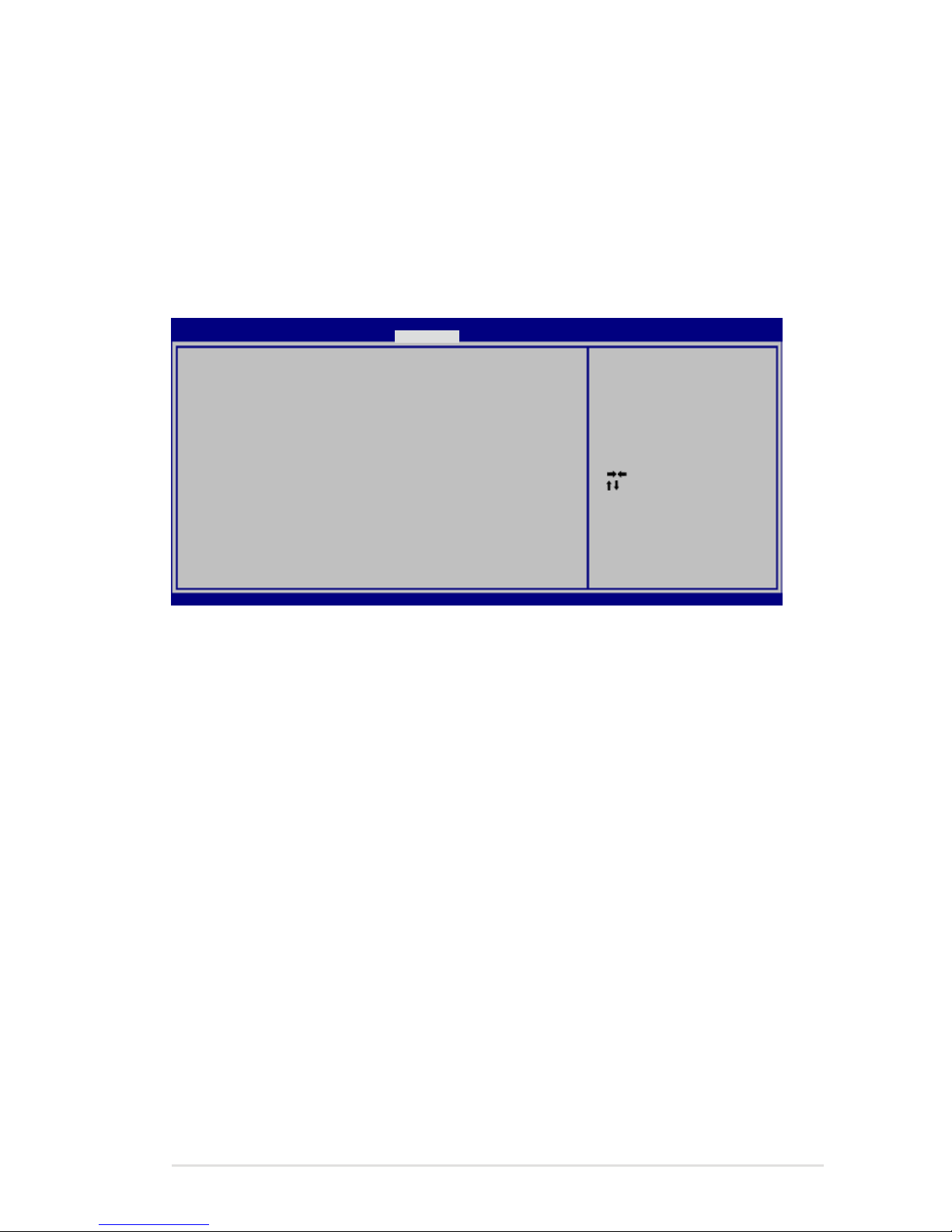
Save Changes
If you want to keep your configuration settings, you must save
changes before exiting the BIOS setup utility.
If you want to restore default settings, choose Restore Defaults. You
must then save changes to keep the manufacture default settings.
: Se le ct S cr ee n
: Se lec t It em
En ter : Se le ct
+/ —: Ch ang e Op t.
F1 : Ge ner al H el p
F9 : Op tim iz ed D ef au lt s
F1 0: Sav e E SC : E xi t
Ve rsi on 2 .0 1. 12 04 . Co py ri gh t (C ) 20 10 A me ri can Megatrends, Inc.
A pt io S et up U tility - Copyright (C) 20 10 Ame ri ca n Me ga tr en ds , In c.
M ai n A dv an ce d B ootMa in A dv an ce d B oo t S ec ur it y S av e & Exit
Sa ve C ha ng es a nd E xi t
Di sc ar d Ch an ge s an d Ex it
Sa ve O pt io ns
Sa ve C ha ng es
Di sc ar d Ch an ge s
Re st or e De fa ul ts
Bo ot O ve rr id e
P0 : ST 96 40 42 3A S
La un ch E FI S he ll f ro m fi le sy st em d ev ic e
Ex it sy st em s et up a ft er s av in g
th e c ha ng es .
Page 72

A-6
Notebook PC User Manual
Common Problems and Solutions
Unknown Reason - System Unstable
Cannot wake up from the hibernation.
1. Remove upgraded parts (RAM, HDD, WLAN, BT) if they were
installed after purchase.
2. If not the case, try MS System Restore to an earlier date.
3. If problem still persists, try restoring your system using the
recovery partition or DVD.
You must backup all your data to another location before
recovering.
4. If the problem still exist, contact your local service center and
ask an engineer for assistance.
Hardware Problem - Keyboard / Hotkey
The Hotkey (FN) is disabled.
A. Reinstall the “ATK0100” driver from the driver CD or download it
from the ASUS website.
Hardware Problem - Built-in Camera
The built-in camera does not work correctly.
1. Check “Device Manager” to see if there are any problems.
2. Try reinstalling the webcam driver to solve the problem.
3. If the problem is not solved, update the BIOS to the latest
version and try again.
4. If the problem still exist, contact your local service center and
ask an engineer for assistance.
Page 73

Notebook PC User Manual
A-7
Hardware Problem - Battery
Battery maintenance.
1. Register the Notebook PC for a one-year-warranty using the
following website:
http://member.asus.com/login.aspx?SLanguage=en-us
2. Do NOT remove the battery pack while using the Notebook
PC with the AC adaptor to prevent damage caused by the
accidental power loss. The ASUS battery pack has protection
circuitry to prevent over-charging so it will not damage the
battery pack if it is left in the Notebook PC.
Hardware Problem - Power ON/OFF Error
I cannot power ON the Notebook PC.
Diagnostics:
1. Power On by Battery only? (Y = 2, N = 4)
2. Able to see BIOS (ASUS Logo)? (Y = 3, N = A)
3. Able to load the OS? (Y = B, N = A)
4. Adapter power LED ON? (Y = 5, N = C)
5. Power ON by Adapter only? (Y = 6, N = A)
6. Able to see BIOS (ASUS Logo)? (Y = 7, N = A)
7. Able to load the OS? (Y = D, N = A)
Symptom & Solutions:
A. Problem might be in the MB, HDD, or NB; visit a local service center
for assistance.
B. Problem caused by the operating system, try restoring your system us-
ing the recovery partition or disc.
IMPORTANT! You must backup all your data to another location
before recovering.
Page 74

A-8
Notebook PC User Manual
C. Adapter problem; check the power cord connections, otherwise visit
a local service center for replacement.
D. Battery problem; please check the battery contacts, otherwise visit a
local service center for repair.
Hardware Problem - Wireless Card
How to check whether a Notebook PC is equipped with a wireless
card?
A. Enter Control Panel -> Device Manager. You will see whether
the Notebook PC has a WLAN card under the “Network Adapter”
item.
Mechanical Problem - FAN / Thermal
Why is the cooling fan always ON and the temperature high?
1. Make sure that the FAN works when the CPU temperature is
high and check whether there is air flow from the main air vent.
2. If you have many applications running (see taskbar), close them
to decrease system load.
3. The problem may also be caused by some viruses, use anti-virus
software to detect them.
4. If none of the above help, try restoring your system using the
recovery partition or DVD.
IMPORTANT! You must backup all your data to another location
before recovering.
CAUTION! DO NOT connect to the Internet before you have
installed an anti-virus software and Internet firewall to protect
yourself from viruses.
Software Problem - ASUS bundled software
When I power ON the Notebook PC, there will be an “Open policy file
error” message.
Page 75
Notebook PC User Manual
A-9
A. Reinstall the latest version “Power4 Gear” utility to solve your
problem. It is available on the ASUS website.
Unknown Reason - Blue screen with white text
A blue screen with white text appears after system bootup.
1. Remove additional memory. If additional memory was installed
after purchase, power OFF, remove the additional memory, and
power ON to see if the problem is due to incompatible memory.
2. Un-install software applications. If you have installed software
applications recently, they may not be compatible with your
system. Try to un-install them in Windows Safe Mode.
3. Check your system for viruses.
4. Update the BIOS to the latest version with Easy Flash in
Windows or AFLASH in DOS mode. These utilities and BIOS files
can be downloaded from the ASUS website.
WARNING! Ensure your Notebook PC does not lose power during
the BIOS flashing process.
5. If problem still cannot be solved, use the recovery process to
reinstall your entire system.
IMPORTANT! You must backup all your data to another location
before recovering.
Page 76
A-10
Notebook PC User Manual
CAUTION! DO NOT connect to the Internet before you have
installed an anti-virus software and Internet firewall to protect
yourself from viruses.
Ensure that you install the “Intel INF Update” and “ATKACPI”
drivers first so that hardware devices can be recognized.
6. If the problem still exist, contact your local service center and
ask an engineer for assistance.
Page 77
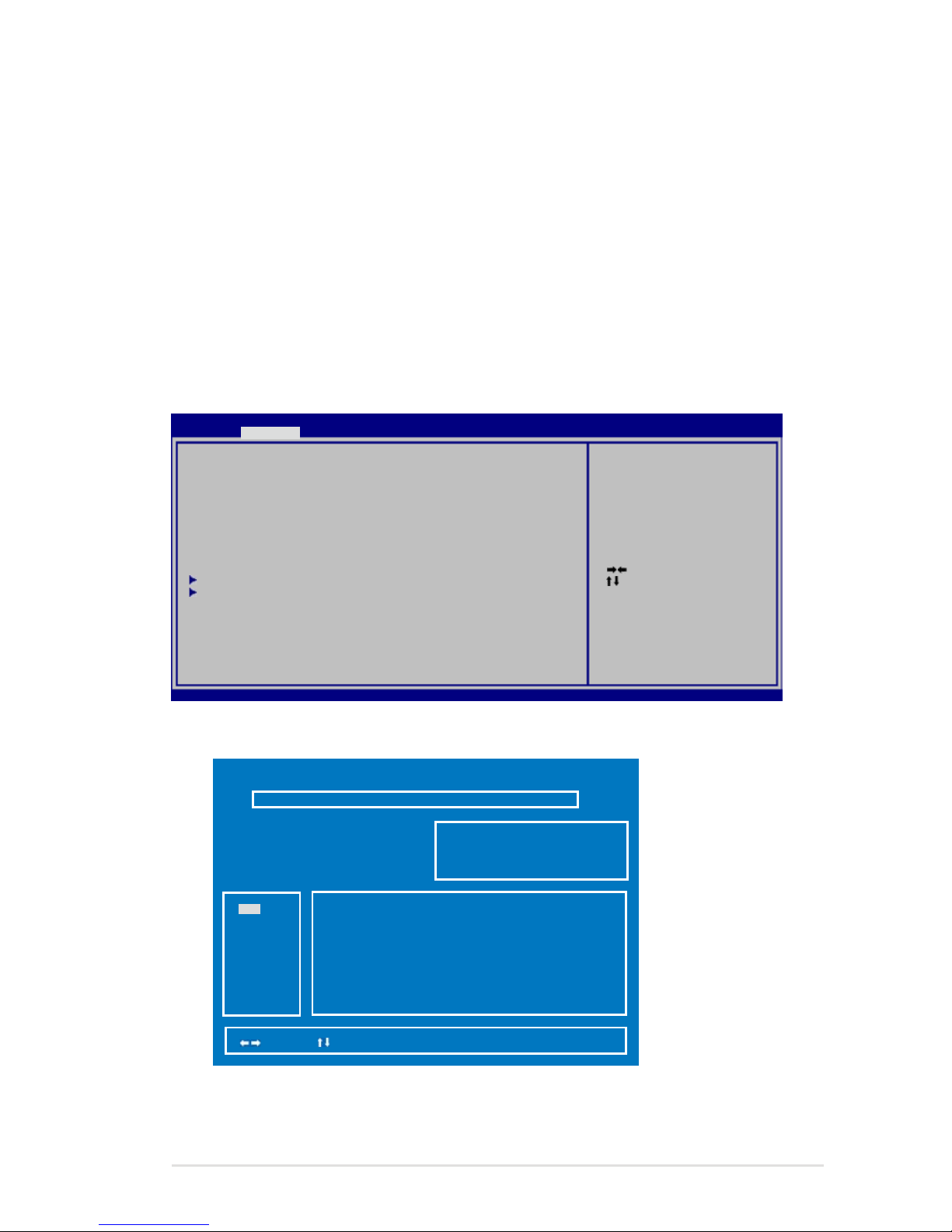
Notebook PC User Manual
A-11
Software Problem - BIOS
Updating the BIOS.
1. Please verify the Notebook PC’s exact model and download the
latest BIOS file for your model from the ASUS website and save
it in your flash disk drive.
2. Connect your flash disk drive to the Notebook PC and power on
the Notebook PC.
3. Use the “Start Easy Flash” function on the Advanced page of the
BIOS Setup Utility. Follow the instructions shown.
4. Locate the latest BIOS file and start updating (flashing) the BIOS.
AS US Te k. E as y Fl as h Ut il it y
[ ]: Swi tc h [ ] : C ho os e [q ] : Ex it
FL ASH T YP E: G en er ic F la sh T yp e
C ur re nt P la tf or m
Pl atf or m: U 56 E
Ve rsi on : 10 3
Bu ild D at e: S ep 1 6 20 10
N ew P la tf or m
Pl atf or m: U nk ow n
Ve rsi on : Un ko wn
Bu ild D at e: U nk ow n
5. You must “Restore Defaults” on the Exit page after updating
(flashing) the BIOS.
: Se le ct S cr ee n
: Se lec t It em
En ter : Se le ct
+/ —: Ch ang e Op t.
F1 : Ge ner al H el p
F9 : Op tim iz ed D ef au lt s
F1 0: Sav e E SC : E xi t
Ve rsi on 2 .0 1. 12 04 . Co py ri gh t (C ) 20 10 A me ri can Megatrends, Inc.
A pt io S et up U tility - Copyright (C) 20 10 Ame ri ca n Me ga tr en ds , In c.
M ai nMa in A dv an ce d B oo t S ec ur it y S av e & Exit
AS US F an cy St ar t [D isa bl ed ]
PO ST L og o Ty pe [S tat ic ]
St ar t Ea sy F la sh
Pl ay P OS T So un d [ No]
Sp ea ke r Vo lu me [4]
In te rn al P oi nt in g De vi ce [E nab le d]
In te l Vi rt ua li za ti on T ec hn ol og y [E nab le d]
Le ga cy U SB S up po rt [E nab le d]
US B CH AR GE [D isa bl e]
SA TA C on fi gu ra ti on
In te l( R) A T Co nf ig ur at io ns
Pr ess E NT ER t o ru n th e ut il it y
to se le ct a nd u pd at e BI OS .
FS 0
FS 1
FS 2
Page 78
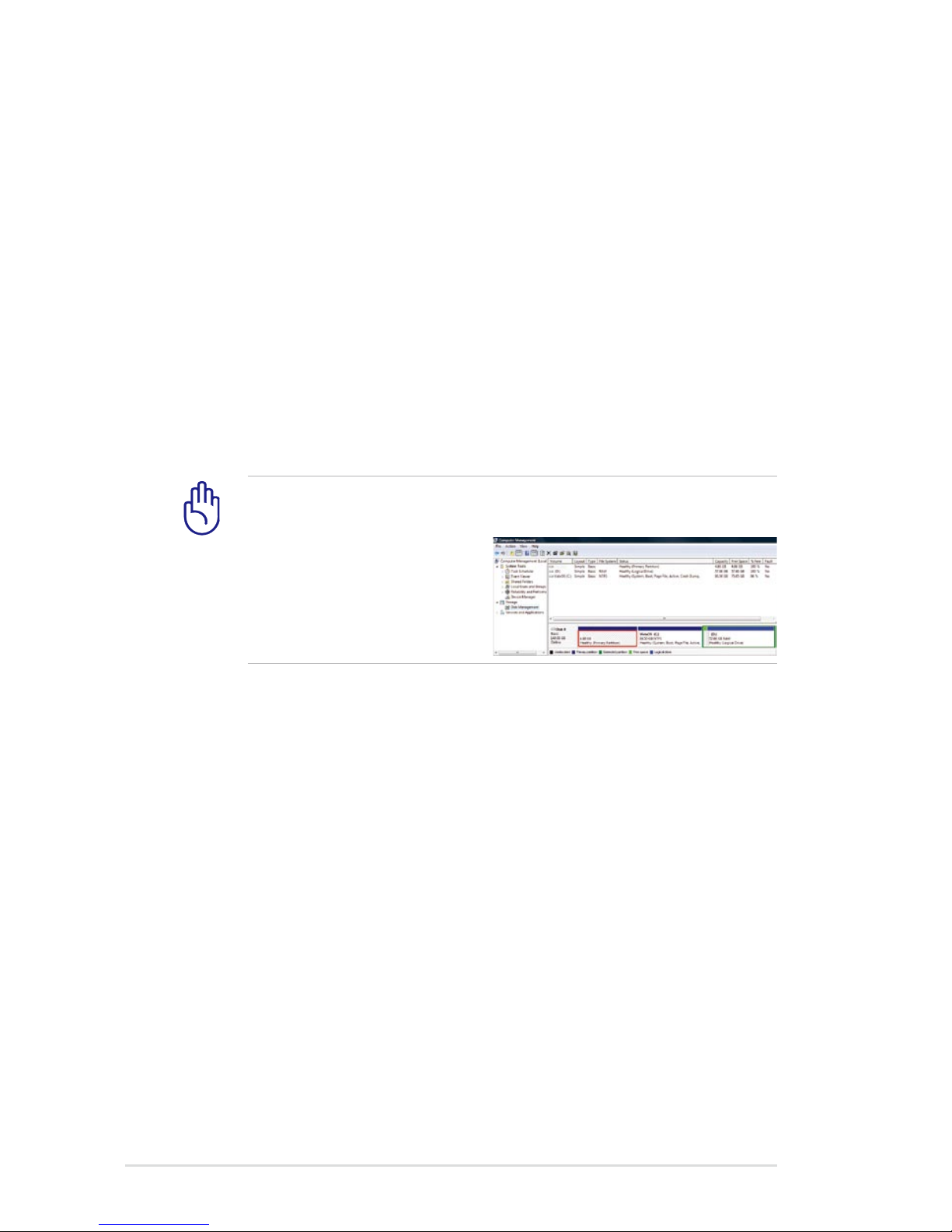
A-12
Notebook PC User Manual
Recovering Your Notebook PC
Using Recovery Partition
The Recovery Partition quickly restores your Notebook PC’s software
to its original working state. Before using the Recovery Partition, copy
your data files (such as Outlook PST files) to USB storage devices or
to a network drive and make note of any customized configuration
settings (such as network settings).
About the Recovery Partition
The Recovery Partition is a reserved space on your hard disk drive
used to restore the operating system, drivers, and utilities installed
on your Notebook PC at the factory.
IMPORTANT! DO NOT delete the partition named RECOVERY.
The Recovery Partition is created at the factory and cannot be
restored if deleted. Take
your Notebook PC to an
authorized ASUS service
center if you have problems
with the recovery process.
Using the Recovery Partition:
1. Press [F9] during bootup.
2. Press [Enter] to select Windows Setup [EMS Enabled].
3. Select the language you want to recover and click Next.
4. Read the ASUS Preload Wizard messages and click Next.
5. Select a partition option and click Next. Partition options:
Recover Windows to first partition only.
This option deletes only the first partition and allows you to keep other
partitions, and to create a new system partition as drive “C”.
Recover Windows to entire HD.
This option deletes all partitions from your hard disk drive and creates
a new system partition as drive “C”.
Page 79
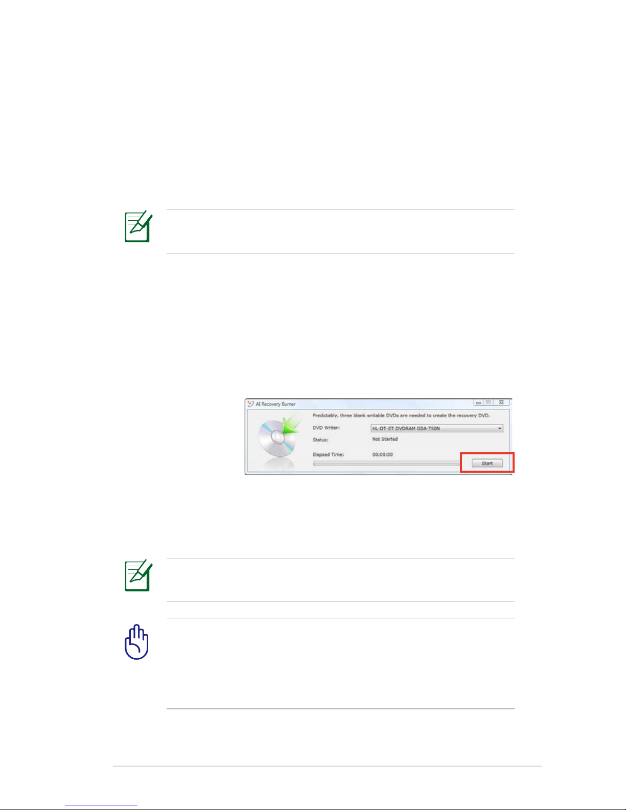
Notebook PC User Manual
A-13
Recover Windows to entire HD with two partitions.
This option deletes all partitions from your hard drive and creates two
new partitions “C” (40%) and “D” (60%).
6. Follow the onscreen instructions to complete the recovery
process.
Visit the ASUS website at www.asus.com for updated drivers and
utilities.
Using Recovery DVD (on selected models)
Creating the Recovery DVD:
1. Double-click the AI Recovery Burner icon on the Window
desktop.
2. Insert a blank
writable DVD
into the optical
drive and click
Start to start
creating the
Recovery DVD.
3. Follow the onscreen instructions to complete creating the
recovery DVD.
Prepare enough blank writable DVDs as instructed to create the
Recovery DVD.
IMPORTANT! Remove the external hard disk drive before
performing system recovery on your Notebook PC. According
to Microsoft, you may lose important data because of setting up
Windows on the wrong disk drive or formatting the incorrect
drive partition.
Page 80
A-14
Notebook PC User Manual
Using the Recovery DVD:DVD::
1. Insert the Recovery DVD into the optical drive. Your Notebook
PC needs to be powered ON.
2. Restart the Notebook PC and press [Esc] on bootup and select
the optical drive (may be labeled as “CD/DVD”) and press [Enter]
to boot from the Recovery DVD.
3. Select OK to start to restore the image.
4. Select OK to confirm the system recovery.
Restoring will overwrite your hard drive. Ensure to back up all
your important data before the system recovery.
5. Follow the onscreen instructions to complete the recovery
process.
WARNING: DO NOT remove the Recovery disc, unless instructed
to do so, during the recovery process or else your partitions will
be unusable.
Ensure to connect the power adapter to your Notebook PC when
performing system recovery. Unstable power supply may cause
recovery failure.
Visit the ASUS website at www.asus.com for updated drivers and
utilities.
Page 81

Notebook PC User Manual
A-15
Internal Modem Compliancy (on
selected models)
The Notebook PC with internal modem model complies with
JATE (Japan), FCC (US, Canada, Korea, Taiwan), and CTR21. The
internal modem has been approved in accordance with Council
Decision 98/482/EC for pan-European single terminal connection
to the public switched telephone network (PSTN). However due
to differences between the individual PSTNs provided in different
countries, the approval does not, of itself, give an unconditional
assurance of successful operation on every PSTN network
termination point. In the event of problems you should contact your
equipment supplier in the first instance.
Overview
On 4th August 1998 the European Council Decision regarding the
CTR 21 has been published in the Official Journal of the EC. The CTR
21 applies to all non voice terminal equipment with DTMF-dialling
which is intended to be connected to the analogue PSTN (Public
Switched Telephone Network).
CTR 21 (Common Technical Regulation) for the attachment
requirements for connection to the analogue public switched
telephone networks of terminal equipment (excluding terminal
equipment supporting the voice telephony justified case service)
in which network addressing, if provided, is by means of dual tone
multifrequency signalling.
Page 82

A-16
Notebook PC User Manual
Network Compatibility Declaration
Statement to be made by the manufacturer to the Notified Body and
the vendor: “This declaration will indicate the networks with which
the equipment is designed to work and any notified networks with
which the equipment may have inter-working difficulties”
Network Compatibility Declaration
Statement to be made by the manufacturer to the user: “This
declaration will indicate the networks with which the equipment
is designed to work and any notified networks with which the
equipment may have inter-working difficulties. The manufacturer
shall also associate a statement to make it clear where network
compatibility is dependent on physical and software switch settings.
It will also advise the user to contact the vendor if it is desired to use
the equipment on another network.”
Up to now the Notified Body of CETECOM issued several panEuropean approvals using CTR 21. The results are Europe’s first
modems which do not require regulatory approvals in each
individual European country.
Non-Voice Equipment
Answering machines and loud-speaking telephones can be eligible
as well as modems, fax machines, auto-dialers and alarm systems.
Equipment in which the end-to-end quality of speech is controlled
by regulations (e.g. handset telephones and in some countries also
cordless telephones) is excluded.
Page 83

Notebook PC User Manual
A-17
This table shows the countries currently under the CTR21
standard.
Country Applied More Testing
Austria1 Yes No
Belgium Yes No
Czech Republic No Not Applicable
Denmark1 Yes Yes
Finland Yes No
France Yes No
Germany Yes No
Greece Yes No
Hungary No Not Applicable
Iceland Yes No
Ireland Yes No
Italy Still Pending Still Pending
Israel No No
Lichtenstein Yes No
Luxemburg Yes No
The Netherlands1 Yes Yes
Norway Yes No
Poland No Not Applicable
Portugal No Not Applicable
Spain No Not Applicable
Sweden Yes No
Switzerland Yes No
United Kingdom Yes No
Page 84

A-18
Notebook PC User Manual
This information was copied from CETECOM and is supplied without
liability. For updates to this table, you may visit http://www.cetecom.
de/technologies/ctr_21.html
1 National requirements will apply only if the equipment may use
pulse dialling (manufacturers may state in the user guide that the
equipment is only intended to support DTMF signalling, which
would make any additional testing superfluous).
In The Netherlands additional testing is required for series
connection and caller ID facilities.
Page 85

Notebook PC User Manual
A-19
Declarations and Safety Statements
Federal Communications Commission Statement
This device complies with FCC Rules Part 15. Operation is subject to
the following two conditions:
• This device may not cause harmful interference.
• This device must accept any interference received, including
interference that may cause undesired operation.
This equipment has been tested and found to comply with the
limits for a class B digital device, pursuant to Part 15 of the Federal
Communications Commission (FCC) rules. These limits are designed
to provide reasonable protection against harmful interference in
a residential installation. This equipment generates, uses, and can
radiate radio frequency energy and, if not installed and used in
accordance with the instructions, may cause harmful interference
to radio communications. However, there is no guarantee that
interference will not occur in a particular installation. If this equipment
does cause harmful interference to radio or television reception,
which can be determined by turning the equipment off and on, the
user is encouraged to try to correct the interference by one or more of
the following measures:
• Reorient or relocate the receiving antenna.
• Increase the separation between the equipment and receiver.
• Connect the equipment into an outlet on a circuit different from
that to which the receiver is connected.
• Consult the dealer or an experienced radio/TV technician for
help.
The use of a shielded-type power cord is required in order to
meet FCC emission limits and to prevent interference to the
nearby radio and television reception. It is essential that only
the supplied power cord be used. Use only shielded cables to
connect I/O devices to this equipment. You are cautioned that
changes or modifications not expressly approved by the party
responsible for compliance could void your authority to operate
the equipment.
Page 86

A-20
Notebook PC User Manual
(Reprinted from the Code of Federal Regulations #47, part 15.193, 1993.
Washington DC: Office of the Federal Register, National Archives and
Records Administration, U.S. Government Printing Office.)
FCC Radio Frequency (RF) Exposure Caution
Statement
Any changes or modifications not expressly approved by the
party responsible for compliance could void the user’s authority
to operate this equipment. “The manufacture declares that
this device is limited to Channels 1 through 11 in the 2.4GHz
frequency by specified firmware controlled in the USA.”
This equipment complies with FCC radiation exposure limits set forth
for an uncontrolled environment. To maintain compliance with FCC
RF exposure compliance requirements, please avoid direct contact
to the transmitting antenna during transmitting. End users must
follow the specific operating instructions for satisfying RF exposure
compliance.
Declaration of Conformity
(R&TTE directive 1999/5/EC)
The following items were completed and are considered relevant
and sufficient:
• Essential requirements as in [Article 3]
• Protection requirements for health and safety as in [Article 3.1a]
• Testing for electric safety according to [EN 60950]
• Protection requirements for electromagnetic compatibility in
[Article 3.1b]
• Testing for electromagnetic compatibility in [EN 301 489-1] & [EN
301 489-17]
• Effective use of the radio spectrum as in [Article 3.2]
• Radio test suites according to [EN 300 328-2]
Page 87
Notebook PC User Manual
A-21
CE Mark Warning
CE marking for devices without wireless LAN/Bluetooth
The shipped version of this device complies with the requirements
of the EEC directives 2004/108/EC “Electromagnetic compatibility”
and 2006/95/EC “Low voltage directive”.
CE marking for devices with wireless LAN/ Bluetooth
This equipment complies with the requirements of Directive 1999/5/
EC of the European Parliament and Commission from 9 March, 1999
governing Radio and Telecommunications Equipment and mutual
recognition of conformity.
IC Radiation Exposure Statement for Canada
This equipment complies with IC radiation exposure limits set forth
for an uncontrolled environment. To maintain compliance with IC
RF exposure compliance requirements, please avoid direct contact
to the transmitting antenna during transmitting. End users must
follow the specific operating instructions for satisfying RF exposure
compliance.
Operation is subject to the following two conditions:
• This device may not cause interference and
• This device must accept any interference, including interference
that may cause undesired operation of the device.
To prevent radio interference to the licensed service (i.e. co-channel
Mobile Satellite systems) this device is intended to be operated
indoors and away from windows to provide maximum shielding.
Equipment (or its transmit antenna) that is installed outdoors is
subject to licensing.
Page 88

A-22
Notebook PC User Manual
Wireless Operation Channel for Different Domains
N. America 2.412-2.462 GHz Ch01 through CH11
Japan 2.412-2.484 GHz Ch01 through Ch14
Europe ETSI 2.412-2.472 GHz Ch01 through Ch13
France Restricted Wireless Frequency Bands
Some areas of France have a restricted frequency band. The worst
case maximum authorized power indoors are:
• 10mW for the entire 2.4 GHz band (2400 MHz–2483.5 MHz)
• 100mW for frequencies between 2446.5 MHz and 2483.5 MHz
Channels 10 through 13 inclusive operate in the band 2446.6 MHz to
2483.5 MHz.
There are few possibilities for outdoor use: On private property or on
the private property of public persons, use is subject to a preliminary
authorization procedure by the Ministry of Defense, with maximum
authorized power of 100mW in the 2446.5–2483.5 MHz band. Use
outdoors on public property is not permitted.
In the departments listed below, for the entire 2.4 GHz band:
• Maximum authorized power indoors is 100mW
• Maximum authorized power outdoors is 10mW
Departments in which the use of the 2400–2483.5 MHz band is
permitted with an EIRP of less than 100mW indoors and less than
10mW outdoors:
01 Ain 02 Aisne 03 Allier
05 Hautes Alpes 08 Ardennes 09 Ariège
11 Aude 12 Aveyron 16 Charente
24 Dordogne 25 Doubs 26 Drôme
32 Gers 36 Indre 37 Indre et Loire
41 Loir et Cher 45 Loiret 50 Manche
55 Meuse 58 Nièvre 59 Nord
Page 89

Notebook PC User Manual
A-23
60 Oise 61 Orne
63 Puy du Dôme 64 Pyrénées Atlantique
66 Pyrénées Orientales 67 Bas Rhin
68 Haut Rhin 70 Haute Saône
71 Saône et Loire 75 Paris
82 Tarn et Garonne 84 Vaucluse
88 Vosges 89 Yonne
90 Territoire de Belfort 94 Val de Marne
This requirement is likely to change over time, allowing you to use
your wireless LAN card in more areas within France. Please check
with ART for the latest information (www.arcep.fr)
Your WLAN Card transmits less than 100mW, but more than
10mW.
Page 90

A-24
Notebook PC User Manual
UL Safety Notices
Required for UL 1459 covering telecommunications (telephone)
equipment intended to be electrically connected to a
telecommunication network that has an operating voltage to
ground that does not exceed 200V peak, 300V peak-to-peak, and
105V rms, and installed or used in accordance with the National
Electrical Code (NFPA 70).
When using the Notebook PC modem, basic safety precautions
should always be followed to reduce the risk of fire, electric shock,
and injury to persons, including the following:
• DO NOT use the Notebook PC near water, for example, near
a bath tub, wash bowl, kitchen sink or laundry tub, in a wet
basement or near a swimming pool.
• DO NOT use the Notebook PC during an electrical storm. There
may be a remote risk of electric shock from lightning.
• DO NOT use the Notebook PC in the vicinity of a gas leak.
Required for UL 1642 covering primary (nonrechargeable) and
secondary (rechargeable) lithium batteries for use as power sources
in products. These batteries contain metallic lithium, or a lithium
alloy, or a lithium ion, and may consist of a single electrochemical
cell or two or more cells connected in series, parallel, or both, that
convert chemical energy into electrical energy by an irreversible or
reversible chemical reaction.
• Do not dispose the Notebook PC battery pack in a fire, as
they may explode. Check with local codes for possible special
disposal instructions to reduce the risk of injury to persons due
to fire or explosion.
• Do not use power adapters or batteries from other devices to
reduce the risk of injury to persons due to fire or explosion. Use
only UL certified power adapters or batteries supplied by the
manufacturer or authorized retailers.
Page 91

Notebook PC User Manual
A-25
Power Safety Requirement
Products with electrical current ratings up to 6A and weighing more
than 3Kg must use approved power cords greater than or equal to:
H05VV-F, 3G, 0.75mm2 or H05VV-F, 2G, 0.75mm2.
REACH
Complying with the REACH (Registration, Evaluation, Authorization,
and Restriction of Chemicals) regulatory framework, we publish
the chemical substances in our products at ASUS REACH website at
http://csr.asus.com/english/REACH.htm.
TV Tuner Notices (on selected models)
Note to CATV System Installer—Cable distribution system should be
grounded (earthed) in accordance with ANSI/NFPA 70, the National
Electrical Code (NEC), in particular Section 820.93, Grounding of
Outer Conductive Shield of a Coaxial Cable – installation should
include bonding the screen of the coaxial cable to the earth at the
building entrance.
Page 92

A-26
Notebook PC User Manual
Nordic Lithium Cautions (for lithium-ion batteries)
CAUTION! Danger of explosion if battery is incorrectly replaced.
Replace only with the same or equivalent type recommended
by the manufacturer. Dispose of used batteries according to the
manufacturer’s instructions. (English)
ATTENZIONE! Rischio di esplosione della batteria se sostituita in
modo errato. Sostituire la batteria con un una di tipo uguale o
equivalente consigliata dalla fabbrica. Non disperdere le batterie
nell’ambiente. (Italian)
VORSICHT! Explosionsgefahr bei unsachgemäßen Austausch der
Batterie. Ersatz nur durch denselben oder einem vom Hersteller
empfohlenem ähnlichen Typ. Entsorgung gebrauchter Batterien
nach Angaben des Herstellers. (German)
ADVARSELI! Lithiumbatteri - Eksplosionsfare ved fejlagtig håndtering.
Udskiftning må kun ske med batteri af samme fabrikat og type. Levér
det brugte batteri tilbage til leverandøren. (Danish)
VARNING! Explosionsfara vid felaktigt batteribyte. Använd
samma batterityp eller en ekvivalent typ som rekommenderas
av apparattillverkaren. Kassera använt batteri enligt fabrikantens
instruktion. (Swedish)
VAROITUS! Paristo voi räjähtää, jos se on virheellisesti asennettu. Vaihda
paristo ainoastaan laitevalmistajan sousittelemaan tyyppiin. Hävitä
käytetty paristo valmistagan ohjeiden mukaisesti. (Finnish)
ATTENTION! Il y a danger d’explosion s’il y a remplacement incorrect
de la batterie. Remplacer uniquement avec une batterie du mêre
type ou d’un type équivalent recommandé par le constructeur.
Mettre au rebut les batteries usagées conformément aux instructions
du fabricant. (French)
ADVARSEL! Eksplosjonsfare ved feilaktig skifte av batteri.
Benytt samme batteritype eller en tilsvarende type anbefalt
av apparatfabrikanten. Brukte batterier kasseres i henhold til
fabrikantens instruksjoner. (Norwegian)
(Japanese)
ВНИМАНИЕ! При замене аккумулятора на аккумулятор иного
типа возможно его возгорание. Утилизируйте аккумулятор в
соответствии с инструкциями производителя. (Russian)
Page 93

Notebook PC User Manual
A-27
Macrovision Corporation Product Notice
This product incorporates copyright protection technology that
is protected by method claims of certain U.S.A. patents and other
intellectual property rights owned by Macrovision Corporation and
other rights owners. Use of this copyright protection technology
must be authorized by Macrovision Corporation, and is intended
for home and other limited viewing uses only
unless otherwise
authorized by Macrovision Corporation
. Reverse engineering or
disassembly is prohibited.
Page 94
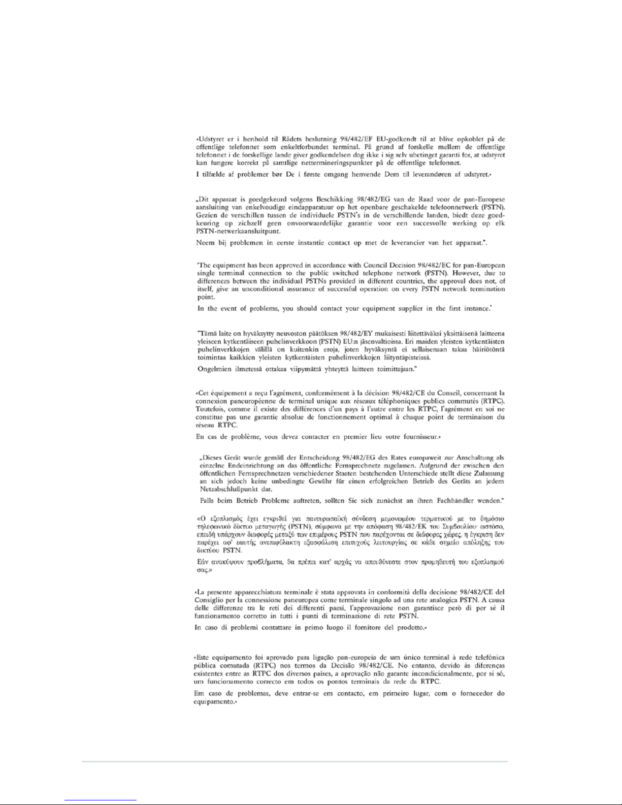
A-28
Notebook PC User Manual
CTR 21 Approval
(for Notebook PC with built-in Modem)
Danish
Dutch
English
Finnish
French
German
Greek
Italian
Portuguese
Page 95
Notebook PC User Manual
A-29
Spanish
Swedish
Page 96

A-30
Notebook PC User Manual
European Union Eco-label
This Notebook PC has been awarded the EU Flower label, which
means that this product has the following characteristics:
1. Decreased energy consumption during use and stand-by
modes.
2. Limited use of toxic heavy metals.
3. Limited use of substances harmful to the environment and
health.
4. Reduction of the use of natural resources by encouraging
recycling.
5. Designed for easy upgrades and longer lifetime through
providing compatible spare parts such as batteries, power
supplies, the keyboard, the memory, and if available the CD drive
or DVD drive.
6. Reduced solid waste through takeback policy.
For more information on the EU Flower label, please visit the
European Union Eco-label website at http://www.ecolabel.eu.
ENERGY STAR complied product
ENERGY STAR is a joint program of the U.S.
Environmental Protection Agency and the U.S.
Department of Energy helping us all save money
and protect the environment through energy
efficient products and practices.
All ASUS products with the ENERGY STAR logo
comply with the ENERGY STAR standard, and the power management
feature is enabled by default. The monitor and computer are
automatically set to sleep after 15 and 30 minutes of user inactivity.
To wake your computer, click the mouse or press any key on the
keyboard. Please visit http://www.energy.gov/powermanagement
for detail information on power management and its benefits to the
environment. In addition, please visit http://www.energystar.gov for
detail information on the ENERGY STAR joint program.
NOTE: Energy Star is NOT supported on Freedos and Linux-based
products.
Page 97

Notebook PC User Manual
A-31
Global Environmental Regulation Compliance and
Declaration
ASUS follows the green design concept to design and manufacture
our products, and makes sure that each stage of the product
life cycle of ASUS product is in line with global environmental
regulations. In addition, ASUS disclose the relevant information
based on regulation requirements.
Please refer to http://csr.asus.com/english/Compliance.htm for
information disclosure based on regulation requirements ASUS is
complied with:
Japan JIS-C-0950 Material Declarations
EU REACH SVHC
Korea RoHS
Swiss Energy Laws
ASUS Recycling/Takeback Services
ASUS recycling and takeback programs come from our commitment
to the highest standards for protecting our environment. We believe
in providing solutions for you to be able to responsibly recycle our
products, batteries, other components as well as the packaging
materials. Please go to http://csr.asus.com/english/Takeback.htm for
detailed recycling information in different regions.
Page 98

A-32
Notebook PC User Manual
Copyright Information
No part of this manual, including the products and software
described in it, may be reproduced, transmitted, transcribed, stored
in a retrieval system, or translated into any language in any form
or by any means, except documentation kept by the purchaser
for backup purposes, without the express written permission of
ASUSTeK COMPUTER INC. (“ASUS”).
ASUS PROVIDES THIS MANUAL “AS IS” WITHOUT WARRANTY OF ANY
KIND, EITHER EXPRESS OR IMPLIED, INCLUDING BUT NOT LIMITED TO
THE IMPLIED WARRANTIES OR CONDITIONS OF MERCHANTABILITY
OR FITNESS FOR A PARTICULAR PURPOSE. IN NO EVENT SHALL ASUS,
ITS DIRECTORS, OFFICERS, EMPLOYEES OR AGENTS BE LIABLE FOR
ANY INDIRECT, SPECIAL, INCIDENTAL, OR CONSEQUENTIAL DAMAGES
(INCLUDING DAMAGES FOR LOSS OF PROFITS, LOSS OF BUSINESS,
LOSS OF USE OR DATA, INTERRUPTION OF BUSINESS AND THE LIKE),
EVEN IF ASUS HAS BEEN ADVISED OF THE POSSIBILITY OF SUCH
DAMAGES ARISING FROM ANY DEFECT OR ERROR IN THIS MANUAL
OR PRODUCT.
Products and corporate names appearing in this manual may or
may not be registered trademarks or copyrights of their respective
companies, and are used only for identification or explanation and to
the owners’ benefit, without intent to infringe.
SPECIFICATIONS AND INFORMATION CONTAINED IN THIS MANUAL
ARE FURNISHED FOR INFORMATIONAL USE ONLY, AND ARE SUBJECT
TO CHANGE AT ANY TIME WITHOUT NOTICE, AND SHOULD NOT
BE CONSTRUED AS A COMMITMENT BY ASUS. ASUS ASSUMES NO
RESPONSIBILITY OR LIABILITY FOR ANY ERRORS OR INACCURACIES
THAT MAY APPEAR IN THIS MANUAL, INCLUDING THE PRODUCTS
AND SOFTWARE DESCRIBED IN IT.
Copyright © 2011 ASUSTeK COMPUTER INC. All Rights Reserved.
Page 99

Notebook PC User Manual
A-33
Limitation of Liability
Circumstances may arise where because of a default on ASUS’ part
or other liability, you are entitled to recover damages from ASUS.
In each such instance, regardless of the basis on which you are
entitled to claim damages from ASUS, ASUS is liable for no more
than damages for bodily injury (including death) and damage to real
property and tangible personal property; or any other actual and
direct damages resulted from omission or failure of performing legal
duties under this Warranty Statement, up to the listed contract price
of each product.
ASUS will only be responsible for or indemnify you for loss, damages
or claims based in contract, tort or infringement under this Warranty
Statement.
This limit also applies to ASUS’ suppliers and its reseller. It is the
maximum for which ASUS, its suppliers, and your reseller are
collectively responsible.
UNDER NO CIRCUMSTANCES IS ASUS LIABLE FOR ANY OF
THE FOLLOWING: (1) THIRD-PARTY CLAIMS AGAINST YOU FOR
DAMAGES; (2) LOSS OF, OR DAMAGE TO, YOUR RECORDS OR DATA;
OR (3) SPECIAL, INCIDENTAL, OR INDIRECT DAMAGES OR FOR ANY
ECONOMIC CONSEQUENTIAL DAMAGES (INCLUDING LOST PROFITS
OR SAVINGS), EVEN IF ASUS, ITS SUPPLIERS OR YOUR RESELLER IS
INFORMED OF THEIR POSSIBILITY.
Service and Support
Visit our multi-language web site at http://support.asus.com
Page 100

A-34
Notebook PC User Manual
 Loading...