

Page 1

E546
1. FEATURES
1.1 The CUW-AM
The CUW-AM motherboard is carefully designed for the demanding PC user who
wants advanced features processed by the fastest processors.
1.1.1 Specifications
• Latest Intel Socket 370 Processor Support
®
Intel Pentium
Intel Celeron™ 66MHz FSB Mendocino core PPGA
• Latest Intel 810 Chipset! The 810 (GMCH+ICH) supports 66/100MHz FSB
and UltraDMA/66.
• Integrated Graphics! Controller supports 3D hyper pipelined architecture, par-
allel data processing and compression, precise pixel interpolation, full 2D hardware acceleration, and motion video acceleration.
• Custom Graphics Driver! You can gain about 12% performance over that of
the standard graphics driver (2D highend graphics WinMark) using the custom
graphics driver. The custom graphics driver also provides more features and
provides selection of higher refresh rates and resolutions.
III 100MHz FSB Coppermine core FC-PGA
Specifications
1. FEATURES
• V ersatile Memory Support! DRAM controller supports asymmetrical address-
ing and two DIMM sockets support Intel PC100-compliant SDRAMs (16, 32,
64, 128, or 256MB) up to 512MB. (supports a maximum of 4 sides)
• Latest Low Pin Count Multi-I/O: Provides two high-speed UAR T compatible
serial ports and one parallel port with EPP and ECP capabilities.
• Integrated IDE! Controller supports UltraDMA/66 up to 66MB/s, UltraDMA/
33 up to 33MB/s, and PIO Mode 4 up to 17MB/s.
• Firmware Hub! Provides security and other latest power computing features.
• Enhanced ACPI & Anti-Boot Virus Protection! Programmable BIOS (Flash
EEPROM), offering enhanced ACPI for W indows 98 compatibility , built-in firmware-based virus protection, and autodetection of most devices for virtually automatic setup.
• Highest Audio Quality! AC’97 DAC/ADC (software audio) built into the au-
dio codec reduces noise to improve audio quality and performance for a SNR
(signal to noise ratio) of +90dB. These features greatly improve voice synthesis
and recognition. If more quality is required, an optional onboard Crystal PCI
audio improves audio quality beyond software audio.
CUW-AM User’s Manual 1
Page 2

1. FEATURES
1. FEATURES
Specifications
1.1.2 Performance
• UltraPerformance! Onboard IDE Bus Master controller with two connectors
• Dual Speeds! CPU frequency can operate at either 66MHz or 100MHz while
• Double or Quadruple the IDE T ransfer Speed! IDE transfers using UltraDMA/
• Concurrent PCI! Concurrent PCI allows multiple PCI transfers from PCI mas-
• SDRAM Optimized Performance! ASUS smart series motherboards support
• ACPI Ready! ACPI provides more Energy Saving Features for future operating
• Extreme Graphics! The integrated motion compensation allows for smooth
that support four IDE devices in two channels. Supports UltraDMA/66,
UltraDMA/33 (IDE DMA Mode 2), PIO Modes 3 & 4, and supports Enhanced
IDE devices, such as Tape Backup, CD-ROM, CD-R/RW, and LS-120 drives.
system memory operates at 100MHz. This asynchronous design can optimize the
VGA performance under shared memory configuration.
33 Bus Master IDE can handle rates up to 33MB/s and up to 66MB/s using
UltraDMA/66 technology. The best of all is that these new technology is compatible with existing ATA-2 IDE specifications so there is no need to upgrade
current IDE devices or cables.
ter buses to memory to CPU.
the new generation memory, Synchronous Dynamic Random Access Memory
(SDRAM), which increases the data transfer rate to 800MB/s max using PC100
SDRAM.
systems (OS) supporting OS Direct Power Management (OSPM) functionality.
With these features implemented in the OS, PCs can be ready around the clock,
yet satisfy all the energy saving standards. To fully utilize the benefits of ACPI,
an ACPI-supported OS such as Windows 98 must be used.
MPEG1 or MPEG2 video playback. Fast 3D graphics engine allows for an exciting gameplay experience.
2
CUW-AM User’s Manual
Page 3

1. FEATURES
1.1.3 Intelligence
• Auto Fan Off: The system fans will power off automatically even in standby
mode. This function reduces both energy consumption and system noise, and is
an important feature in implementing silent PC systems.
• Dual Function Power Button: Pushing the power button for less than 4 sec-
onds when the system is in the working state places the system into one of two
states: sleep mode or soft-off mode, depending on the BIOS or OS setting. When
the power button is pressed for more than 4 seconds, the system enters the softoff mode regardless of the BIOS setting.
Specifications
1. FEATURES
CUW-AM User’s Manual 3
Page 4
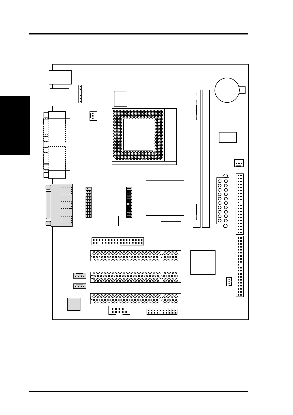
2.1 CUW-AM Motherboard Layout
PS2KBMS
T: Mouse
B: Keyboard
Motherboard Layout
2. H/W SETUP
USB
T: Port 1
B: Port 2
2. HARDWARE SETUP
USBV1
Power
Controller
CR2032 3V
Lithium Cell
CMOS Power
COM1
PARALLEL PORT
VGA
Line
Out
Line
In
Mic
GAME_AUDIO
In
SYS_FAN
FLOPPY
LCDTV
Super
I/O
Socket 370
Intel 810
Graphics &
Memory
Controller
Hub (GMCH)
4Mbit
Firmware
Hub
(FWH)
CUW-AM
PCI Slot 1
Clock
Generator
PS_FAN
DIMM Socket 1 (64/72-bit, 168-pin module)
DIMM Socket 2 (64/72-bit, 168-pin module)
SECONDARY IDEPRIMARY IDE
Row
01
0
1
3
2
ATXPWR
Intel I/O
Controller
CD_IN
AUX_IN
Audio
Codec
PCI Slot 2
PCI Slot 3
PANEL
Hub (ICH)
WOL_CON
COM2
4
CUW-AM User’s Manual
Page 5

2. HARDWARE SETUP
2.2 Layout Contents
Expansion Slots
1) DIMM1, DIMM2 p. 7 168-Pin DIMM Memory Support
2) Socket 370 p. 9 Central Processing Unit (CPU) Socket
3) PCI1, PCI2, PCI3 p.10 32-bit PCI Bus Expansion Slots
Connectors
1) PS2KBMS p.11 PS/2 Mouse Connector (6-pin female)
2) PS2KBMS p.11 PS/2 Keyboard Connector (6-pin female)
3) USB p.12 Universal Serial Bus Ports 1 & 2 (Two 4-pin female)
4) PRINTER p.12 Parallel Port Connector (25-pin female)
5) COM1 p.12 Serial Port COM1 Connector (9-pin male)
6) VGA p.13 Monitor (VGA) Output Connector (15-pin female)
7) GAME_AUDIO p.13 Game/MIDI Connector (15-pin female) (optional)
8) GAME_AUDIO p.13 Audio Port Connectors (Three 1/8” female) (optional)
9) PRIMAR Y/SECONDARY IDE p.14 Primary/Secondary IDE Connectors (Two 40-1pins)
10) FLOPPY p.14 Floppy Disk Drive Connector (34-1pins)
11) WOL_CON p.15 Wake-On-LAN Connector (3 pins)
12) COM2 p.15 Serial Port COM2 Header (10-1 pins)
13) CPU_FAN, PS_FAN p.16 CPU and Power Supply Fan Connectors (3 pins)
14) LCDTV p.16 TV Out Connector (Two 20-1 pins)
15) CD_IN, AUX_IN p.17 Internal Audio Connector (4-pins) (optional)
16) USBV1 p.17 USB Header (6-1 pins)
17) MLED (PANEL) p.18 System Message LED (2 pins)
18) KLOCK (PANEL) p.18 Keyboard Lock Switch Lead (2 pins)
19) EXSMI (PANEL) p.18 System Management Interrupt Switch Lead (2 pins)
20) SPEAKER (PANEL) p.18 System Warning Speaker Connector (4 pins)
21) PWR (PANEL) p.18 ATX Power / Soft-Off Switch Lead (2 pins)
22) HDLED (PANEL) p.18 IDE Activity LED (2 pins)
23) PLED (PANEL) p.19 System Power LED Lead (3-1 pins)
24) RESET (PANEL) p.19 Reset Switch Lead (2 pins)
25) ATXPWR p.20 ATX Power Supply Connector (20 pins)
2. H/W SETUP
Layout Contents
CUW-AM User’s Manual 5
Page 6

2.3 Hardware Setup Procedure
Before using your computer, you must complete the following steps:
• Check Motherboard Settings
• Install Memory Modules
• Install the Central Processing Unit (CPU)
Motherboard Settings
2. H/W SETUP
• Install Expansion Cards
• Connect Ribbon Cables, Panel Wires, and Power Supply
2.4 Motherboard Settings
WARNING! Computer motherboards and expansion cards contain very delicate
Integrated Circuit (IC) chips. To protect them against damage from static electricity, you should follow some precautions whenever you work on your computer.
1. Unplug your computer when working on the inside.
2. Use a grounded wrist strap before handling computer components. If you do
not have one, touch both of your hands to a safely grounded object or to a metal
object, such as the power supply case.
2. HARDWARE SETUP
3. Hold components by the edges and try not to touch the IC chips, leads or connectors, or other components.
4. Place components on a grounded antistatic pad or on the bag that came with the
component whenever the components are separated from the system.
5. Ensure that the ATX power supply is switched off before you plug in or
remove the ATX power connector on the motherboard.
WARNING! Make sure that you unplug your power supply when adding or
removing system components. Failure to do so may cause severe damage to
your motherboard, peripherals, and/or components. The onboard LED when
lit acts as a reminder that the system is in suspend or soft-off mode and not
powered OFF.
6
CUW-AM User’s Manual
Page 7
2. HARDWARE SETUP
2.5 System Memory (DIMM)
NOTE: No hardware or BIOS setup is required after adding or removing memory.
This motherboard uses only Dual Inline Memory Modules (DIMMs). S ockets are
available for 3.3Volt (power level) unbuffered Synchronous Dynamic Random Ac-
cess Memory (SDRAM) of 16, 32, 64, 128MB, or 256MB.
This chipset does not support ECC. However, ECC memory modules may still be
used, but the ECC function will not be available.
Install memory in any combination as follows:
Location 168-pin DIMM SDRAM Total Memory
DIMM1 Single-Sided/Double-Sided x1
(Rows 0&1) 16, 32, 64, 128MB, or 256MB
DIMM2 Single-Sided/Double-Sided x1
(Rows 2&3)
16, 32, 64, 128MB, or 256MB
2. H/W SETUP
System Memory
Total System Memory (Max 512MB) =
2.5.1 General DIMM Notes
• ASUS motherboards support SPD (Serial Presence Detect) DIMMs. This is the
memory of choice for best performance vs. stability.
• SDRAM chips are generally thinner with higher pin density than EDO (Extended
Data Output) chips.
• Single-sided DIMMs come in 16, 32, 64,128MB; double-sided come in 32, 64,
128, 256MB.
CUW-AM User’s Manual 7
Page 8
2. HARDWARE SETUP
2.5.2 DIMM Installation
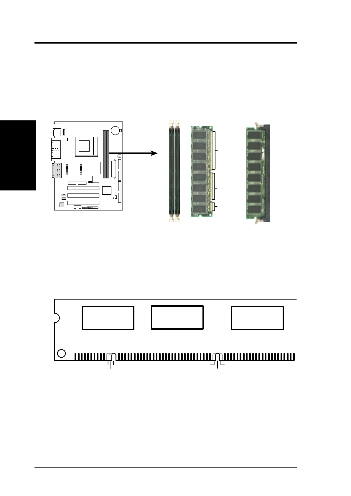
Insert the module(s) as shown. Because the number of pins are different on either
side of the breaks, the module will only fit in the orientation shown. DIMM modules are longer and have different pin contact on each side and therefore have a
higher pin density. SIMMs have the same pin contact on both sides.
System Memory
2. H/W SETUP
CUW-AM 168-Pin DIMM Sockets
The DIMMs must be 3.3V Unbuffered for this motherboard. To determine the DIMM
type, check the notches on the DIMMs (see figure below).
CUW-AM
Lock
88 Pins
0 1
60 Pins
20 Pins
FRONT
168-Pin DIMM Notch Key Definitions (3.3V)
DRAM Key Position
RFU
Buffered
Unbuffered
Voltage Key Position
5.0V
Reserved
3.3V
The notches on the DIMM will shift between left, center, or right to identify the type
and also to prevent the wrong type from being inserted into the DIMM slot on the
motherboard. You must ask your retailer the correct DIMM type before purchasing.
This motherboard supports four clock signals per DIMM slot.
8 CUW-AM User’s Manual
Page 9
2. HARDWARE SETUP
2.6 Central Processing Unit (CPU)
The motherboard provides a ZIF Socket 370. The CPU that came with the motherboard should have a fan attached to it to prevent overheating. If this is not the case,
then purchase a fan before you turn on your system.
WARNING! Be sure that there is sufficient air circulation across the processor’s
heatsink by regularly checking that your CPU fan is working. W ithout sufficient
circulation, the processor could overheat and damage both the processor and the
motherboard. You may install an auxiliary fan, if necessary.
CPU
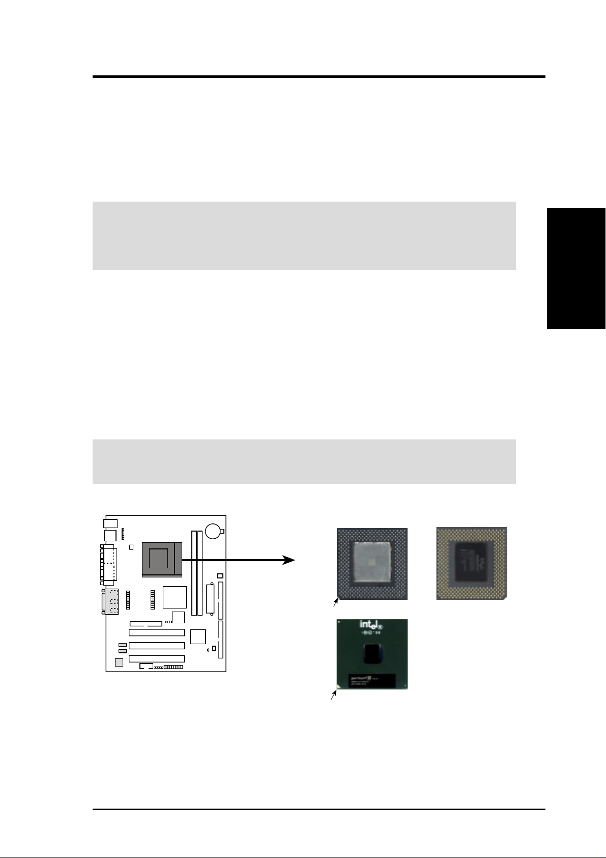
To install a CPU, first turn off your system and remove its cover. Locate the ZIF
socket and open it by first pulling the lever sideways away from the socket then
upwards to a 90-degree angle. Insert the CPU with the correct orientation as shown.
The notched corner should point towards the end of the lever . Because the CPU has
a corner pin for two of the four corners, the CPU will only fit in the orientation as
shown. The picture is for reference only; you should have a CPU fan that covers the
face of the CPU. With the added weight of the CPU fan, no force is required to
insert the CPU. Once completely inserted, close the socket’s lever while holding
down the CPU.
CAUTION! Be careful not to scrape the motherboard when mounting a clamp-
style processor fan or else damage may occur to the motherboard.
Socket 370 CPU
(Top)
Socket 370 CPU
(Bottom)
2. H/W SETUP
0 1
CUW-AM
CUW-AM Socket 370
Notch
Gold Arrow
Celeron
Coppermine
CUW-AM User’s Manual 9
Page 10
2. HARDWARE SETUP
2.7 Expansion Cards
WARNING! Make sure that you unplug your power supply when adding or
removing expansion cards or other system components. Failure to do so may
cause severe damage to both your motherboard and expansion cards.
Expansion Cards
2. H/W SETUP
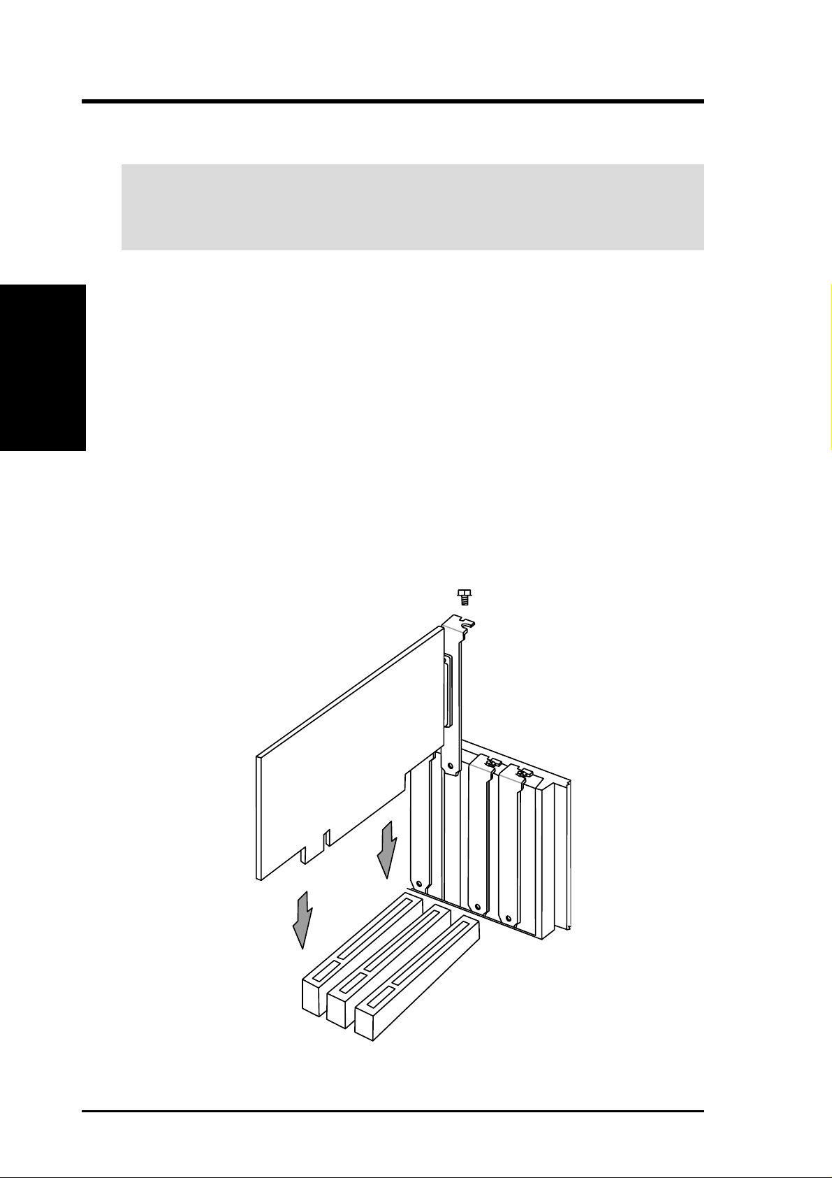
2.7.1 Expansion Card Installation Procedure
1. Read the documentation for your expansion card and make any necessary hardware or software settings for your expansion card, such as jumpers or switches.
2. Remove your computer system’s cover and the bracket plate with screw on the
slot you intend to use. Keep the bracket for possible future use.
3. Carefully align the card’s connectors and press firmly.
4. Secure the card on the slot with the screw you removed above.
5. Replace the computer system’s cover.
6. Set up the BIOS if necessary.
7. Install the necessary software drivers for your expansion card.
10 CUW-AM User’s Manual
Page 11
2. HARDWARE SETUP
2.8 External Connectors
WARNING! Some pins are used for connectors or power sources. These are
clearly distinguished from jumpers in the Motherboard Layout. Placing jumper
caps over these connector pins will cause damage to your motherboard.
IMPORTANT: Ribbon cables should always be connected with the red stripe to
Pin 1 on the connectors. Pin 1 is usually on the side closest to the power connector on hard drives and CD-ROM drives, but may be on the opposite side on
floppy disk drives. Check the connectors before installation because there may
be exceptions. IDE ribbon cable must be less than 46 cm (18 in.), with the second drive connector no more than 15 cm (6 in.) from the first connector.
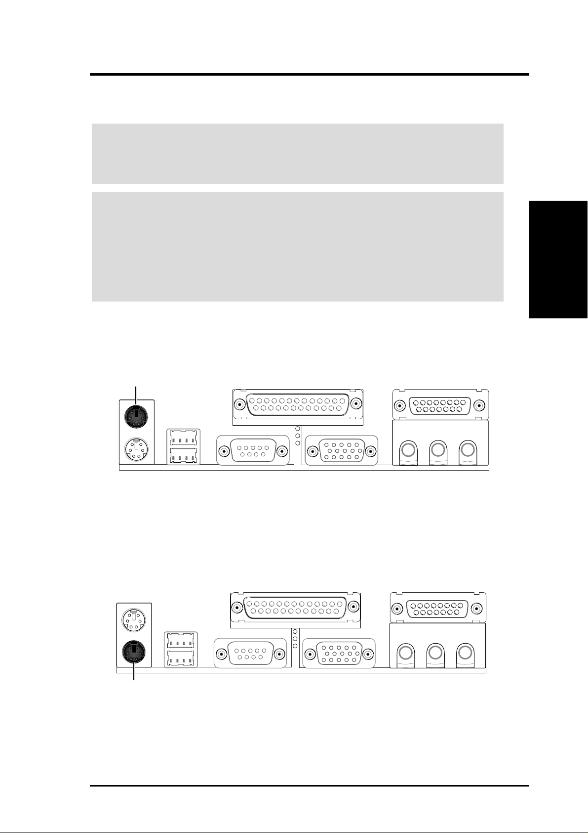
1) PS/2 Mouse Connector (6-pin PS2KBMS)
The system will direct IRQ12 to the PS/2 mouse if one is detected.
Connectors
2. H/W SETUP
PS/2 Mouse (6-pin Female)
2) PS/2 Keyboard Connector (6-pin PS2KBMS)
This connection is for a standard keyboard using an PS/2 plug (mini DIN). This
connector will not allow standard AT size (large DIN) keyboard plugs. You
may use a DIN to mini DIN adapter on standard AT keyboards.
PS/2 Keyboard (6-pin Female)
CUW-AM User’s Manual 11
Page 12
2. H/W SETUP
Connectors
2. HARDWARE SETUP
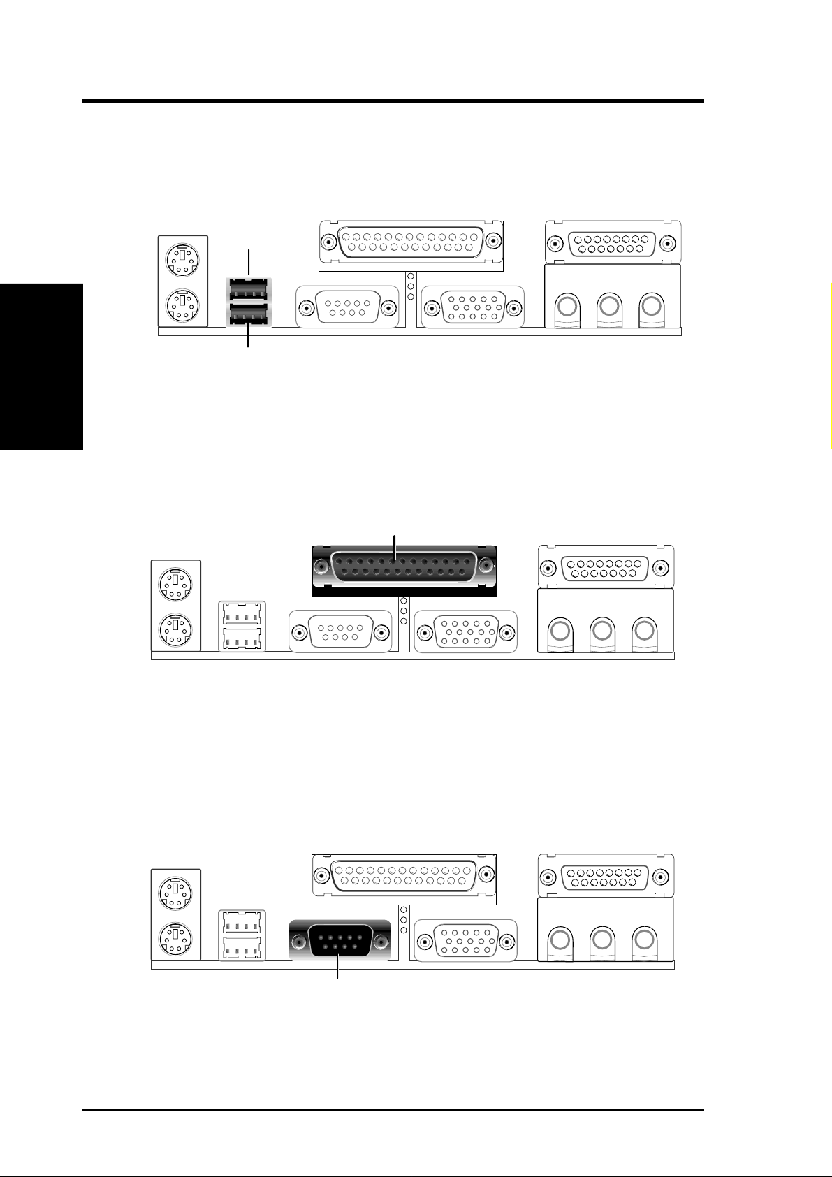
3) Universal Serial Bus Ports (Two 4-pin USB)
Two USB ports are available for connecting USB devices.
USB 1
Universal Serial Bus (USB) 2
4) Parallel Port Connector (25-pin PRINTER)
The parallel connector is used for a single parallel device such as a printer or a
portable drive.
NOTE: Serial printers must be connected to the serial port.
Parallel (Printer) Port (25-pin Female)
5) Serial Port Connector (9-pin COM1)
One serial port is ready for a mouse or other serial devices. A second serial port
is available using a serial port bracket connected from the motherboard to an
expansion slot opening.
Serial Port (9-pin Male) COM 1
12 CUW-AM User’s Manual
Page 13
2. HARDWARE SETUP
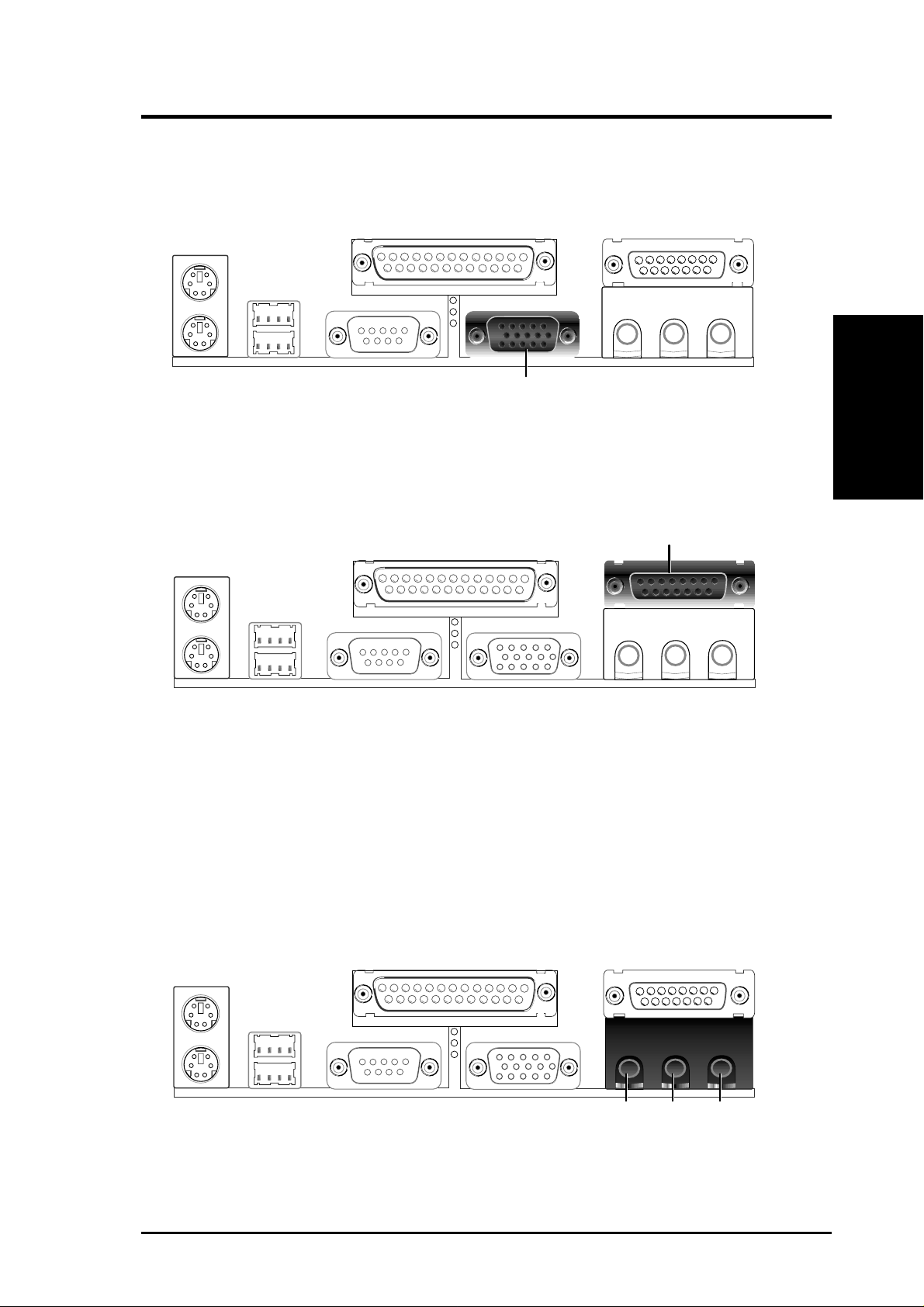
6) Monitor Output Connector (15-pin VGA)
This connector is for output to a VGA-compatible device.
VGA Monitor (15-pin Female)
7) Game/MIDI Connector (15-pin GAME_AUDIO) (optional)
You may connect game joysticks or game pads to this connector for playing
games. Connect MIDI devices for playing or editing professional audio.
Joystick/Midi (15-pin Female)
Connectors
2. H/W SETUP
NOTE: The onboard game port is to be used only if you are not using any PCI
or ISA audio card with a game port.
8) Audio Port Connectors (Three 1/8” GAME_AUDIO) (optional)
Line Out (lime) can be connected to headphones or preferably powered speak-
ers. Line In (light blue) allows tape players or other audio sources to be re-
corded by your computer or played through the Line Out (lime). Mic (pink)
allows microphones to be connected for inputting voice.
MicLine InLine Out
1/8" Stereo Audio Connectors
CUW-AM User’s Manual 13
Page 14
2. H/W SETUP
Connectors
2. HARDWARE SETUP
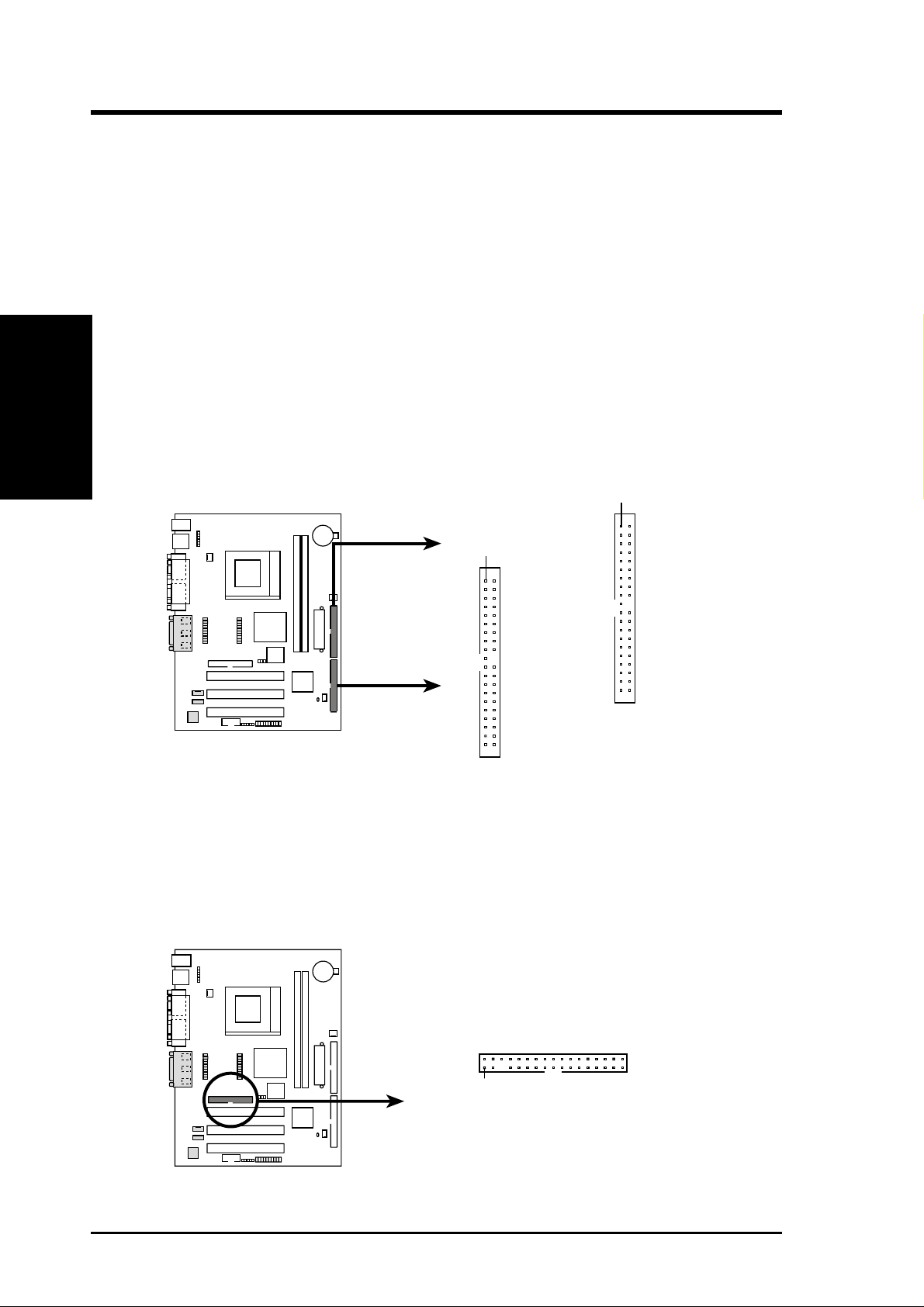
9) Primary / Secondary IDE Connectors
(40-1pin PRIMARY/SECONDARY IDE)
These connectors support the provided IDE hard disk ribbon cable.
After connecting the single end to the board, connect the two plugs at the other
end to your hard disk(s). If you install two hard disks, you must configure the
second drive to Slave mode by setting its jumper accordingly. Please refer to
your hard disk documentation for the jumper settings. (Pin 20 is removed to
prevent inserting in the wrong orientation when using ribbon cables with
pin 20 plugged).
TIP: You may configure two hard disks to be both Masters with two ribbon
cables – one for the primary IDE connector and another for the secondary IDE
connector and select the boot disk through the BIOS.
IMPORTANT: UltraDMA/66 IDE devices must use an 80-wire IDE cable or
else devices will automatically be limited to UltraDMA/33 mode.
PIN 1
PIN 1
0 1
CUW-AM
CUW-AM IDE Connectors
Primary IDE Connector
NOTE: Orient the red markings
on the IDE ribbon cable to
Secondary IDE Connector
PIN 1
10) Floppy Disk Drive Connector (34-1pin FLOPPY)
This connector supports the provided floppy drive ribbon cable. After connecting the single end to the board, connect the two plugs on the other end to the
floppy drives. (Pin 5 is removed to prevent inserting in the wrong orienta-
tion when using ribbon cables with pin 5 plugged).
NOTE: Orient the red markings on
the floppy ribbon cable to
PIN 1
0 1
CUW-AM
CUW-AM Floppy Disk Drive Connector
PIN 1
14 CUW-AM User’s Manual
Page 15
2. HARDWARE SETUP
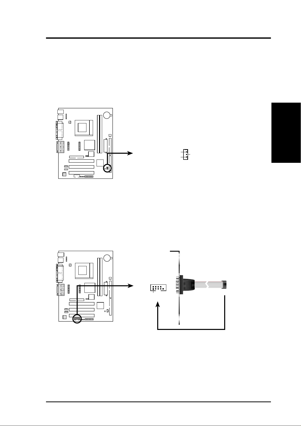
11) Wake-On-LAN Connector (3-pin WOL_CON)
This connector connects to a LAN card with a Wake-On-LAN output. The connector powers up the system when a wakeup packet or signal is received through
the LAN card.
IMPORTANT: This feature requires that your system has an ATX power supply
with at least 720mA +5V standby power.
IMPORTANT: Requires an ATX power
supply with at least 720mA +5 volt
standby power
PME
Ground
CUW-AM
0 1
+5 Volt Standby
CUW-AM Wake-On-LAN Connector
12) Serial Port Header (10-1 pin COM2)
The optional serial port bracket can be used to add an additional serial port for
additional serial devices.
to COM2 Header
CUW-AM
0 1
PIN 1
Connectors
2. H/W SETUP
CUW-AM Serial COM2 Bracket
CUW-AM User’s Manual 15
Page 16
2. H/W SETUP
Connectors
2. HARDWARE SETUP
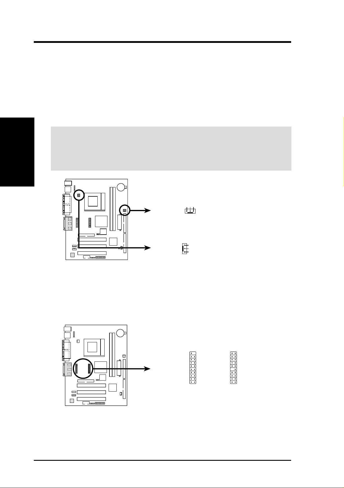
13) CPU and Power Supply Fan Connectors (3-pin CPU_FAN, PS_FAN)
Orientate the fan so that the heat sink fins allow airflow to go across the onboard
heat sink(s) instead of the expansion slots. Depending on the fan manufacturer,
the wiring and plug may be different. The red wire should be positive, while the
black should be ground. Connect the fan’s plug to the board taking into consid-
eration the polarity of the connector.
NOTE: The “Rotation” signal cannot be monitored on this motherboard.
WARNING! The CPU and/or motherboard will overheat if there is no airflow
across the CPU and onboard heatsinks. Damage may occur to the motherboard
and/or the CPU fan if these pins are incorrectly used. These are not jumpers,
do not place jumper caps over these pins.
GND
Rotation
+12V
PS_FAN
0 1
CUW-AM
CUW-AM 12-Volt Cooling Fan Power
GND
+12V
Rotation
SYS_FAN
CPU_FAN
14) LCD-TV Headers (Two 20-1 pin LCDTV)
These headers require an optional LCD module for LCD output or a TV-out
module for TV output.
LCDTV
1
0 1
CUW-AM
CUW-AM LCD-TV Headers
16 CUW-AM User’s Manual
Page 17
2. HARDWARE SETUP
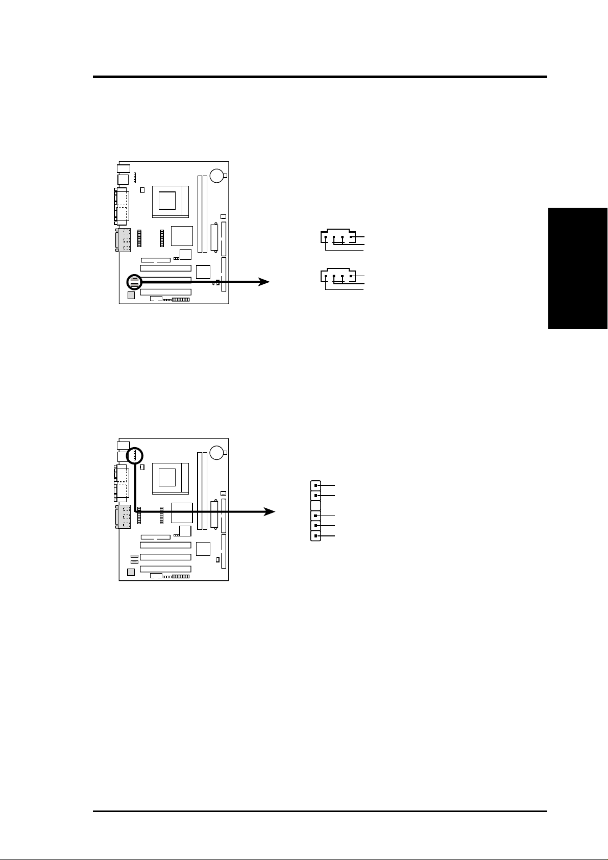
15) Internal Audio Connector (4-pin AUX_IN, CD_IN) (optional)
These connectors allow you to receive stereo audio input from such sound sources
as a CD-ROM, TV tuner, or MPEG card.
CD_IN (Black)
Left Audio Channel
0 1
CUW-AM
AUX_IN (White)
CUW-AM Internal Audio Connector
16) USB Header (6-1 pin USBV1)
If the USB port connectors on the back panel are inadequate, a USB header is
available for additional USB port connectors. Connect the USB header to an
optional USB connector set and mount it to an open slot on your chassis.
Ground
Right Audio Channel
Left Audio Channel
Ground
Right Audio Channel
Connectors
2. H/W SETUP
0 1
CUW-AM
CUW-AM USB Header
GND
USB Power
USBPUSBP+
GND
USBV1
CUW-AM User’s Manual 17
Page 18
2. HARDWARE SETUP
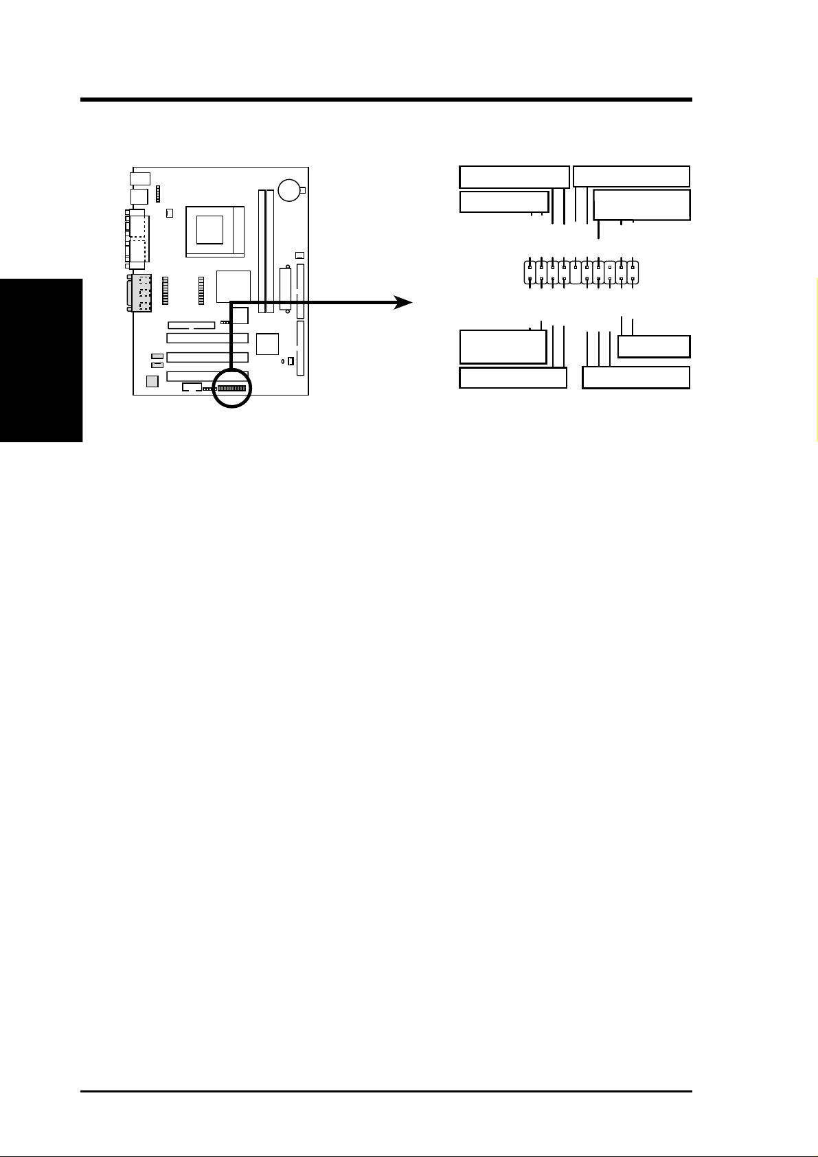
The following PANEL illustration is used for items 17-24
2. H/W SETUP
Connectors
CUW-AM
Keyboard Lock
Message LED
MSGLED+
0 1
PWRBTN
ATX Power
Switch*
HDLED
*
Requires an ATX power supply.
External SMI Lead
Ground
Ground
ExtSMI#
Keylock
MSGLED-
Ground
IDELED-
IDELED+
PWRLED+
Speaker
Connector
Speaker
+5V
Reset Ground
Ground
PWRLED-
PWRLED-
Reset SW
Power LED
CUW-AM System Panel Connectors
17) Message LED Lead (2-pin MLED)
This indicates whether a message has been received from a fax/modem. The
LED will remain lit when there is no signal and flash when there is data received. This function requires an ACPI OS as well as application and driver
support.
18) Keyboard Lock Switch Lead (2-pin KLOCK)
This 2-pin connector connects to the case-mounted key switch to allow keyboard locking.
19) System Management Interrupt Lead (2-pin EXSMI)
This allows the user to manually place the system into a suspend mode or “Green”
mode, where system activity is decreased to save electricity and expand the life
of certain components when the system is not in use. This 2-pin connector connects to the case-mounted suspend switch.
20) System Warning Speaker Connector (4-pin SPEAKER)
This 4-pin connector connects to the case-mounted speaker.
21) Reset Switch Lead (2-pin RESET)
This 2-pin connector connects to the case-mounted reset switch for rebooting
your computer without having to turn off your power switch. This is a preferred
method of rebooting to prolong the life of the system’s power supply.
22) System Power LED Lead (3-1 pin PLED)
This 3-1 pin connector connects the system power LED, which lights when the
system is powered ON and flashes when it is in standby (suspend) mode.
18 CUW-AM User’s Manual
Page 19
2. HARDWARE SETUP
23) IDE Activity LED (2-pin HDLED)
This connector supplies power to the cabinet’s IDE activity LED. Read and
write activity by devices connected to the Primary or Secondary IDE connector
will cause the LED to light up.
24) ATX Power Switch Lead (2-pin PWR)
The system power is controlled by a momentary switch connected to this lead.
Pressing the button once will switch the system between ON and SOFT OFF.
Pushing the switch while in the ON mode for more than 4 seconds will turn the
system off. The system power LED shows the status of the system’s power.
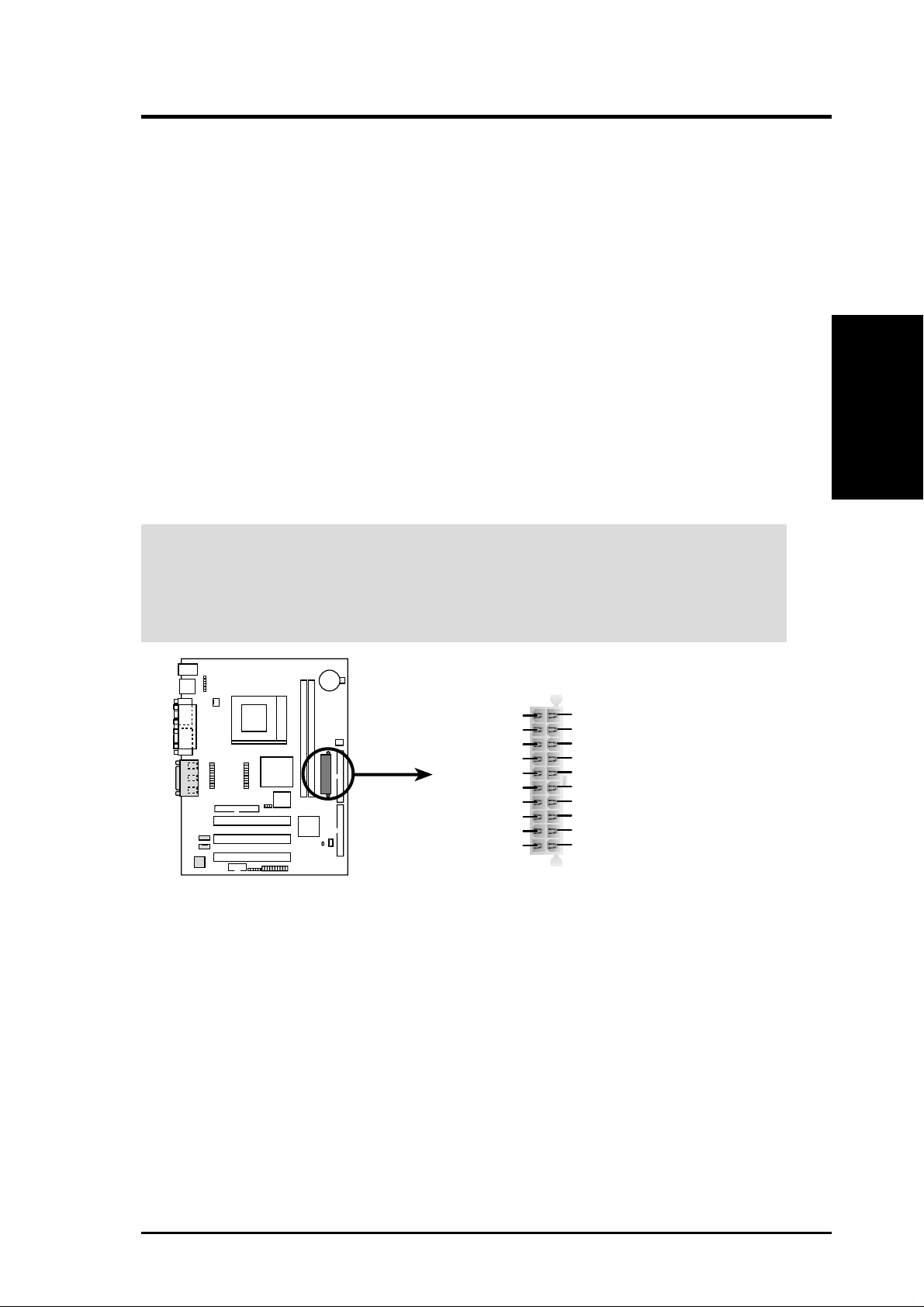
25) ATX Power Supply Connector (20-pin block ATXPWR)
This connector connects to an ATX power supply. The plug from the power supply will only insert in one orientation because of the different hole sizes. Find the
proper orientation and push down firmly making sure that the pins are aligned.
Connectors
2. H/W SETUP
IMPORTANT: Make sure that your ATX power supply can supply at least 10mA
on the +5-volt standby lead (+5VSB). You may experience difficulty in powering ON your system if your power supply cannot support the load. For WakeOn-LAN support, your ATX power supply must supply at least 720mA +5VSB.
0 1
CUW-AM
CUW-AM ATX Power Connector
+12.0 Volts
+5V Standby
Power Good
Ground
+5.0 Volts
Ground
+5.0 Volts
Ground
+3.3 Volts
+3.3 Volts
+5.0 Volts
+5.0 Volts
-5.0 Volts
Ground
Ground
Ground
Power Supply On
Ground
-12.0 Volts
+3.3 Volts
CUW-AM User’s Manual 19
Page 20

2. H/W SETUP
Connectors
2. HARDWARE SETUP
(This page was intentionally left blank.)
20 CUW-AM User’s Manual
 Loading...