

Page 1

CUSL-L
Intel® 815 microATX Motherboard
USER’S MANUAL
Page 2

2 CUSL-L User’s Manual
USER'S NOTICE
Product Name: CUSL-L
Manual Revision: 1.00 E648
Release Date: November 2000
No part of this manual, including the products and software described in it, may be reproduced, transmitted, transcribed, stored in a retrieval system, or translated into any language in
any form or by any means, except documentation kept by the purchaser for backup purposes,
without the express written permission of TeK COMPUTER INC. (“”).
PROVIDES THIS MANUAL “AS IS” WITHOUT WARRANTY OF ANY KIND, EITHER
EXPRESS OR IMPLIED, INCLUDING BUT NOT LIMITED TO THE IMPLIED WARRANTIES OR CONDITIONS OF MERCHANT ABILITY OR FITNESS FOR A PARTICULAR PURPOSE. IN NO EVENT SHALL , ITS DIRECTORS, OFFICERS, EMPLOYEES
OR AGENTS BE LIABLE FOR ANY INDIRECT, SPECIAL, INCIDENTAL, OR CONSEQUENTIAL DAMAGES (INCLUDING DAMAGES FOR LOSS OF PROFITS, LOSS OF
BUSINESS, LOSS OF USE OR DA T A, INTERRUPTION OF BUSINESS AND THE LIKE),
EVEN IF HAS BEEN ADVISED OF THE POSSIBILITY OF SUCH DAMAGES ARISING FROM ANY DEFECT OR ERROR IN THIS MANUAL OR PRODUCT.
Product warranty or service will not be extended if: (1) the product is repaired, modified or
altered, unless such repair, modification of alteration is authorized in writing by ; or (2) the
serial number of the product is defaced or missing.
Products and corporate names appearing in this manual may or may not be registered trademarks or copyrights of their respective companies, and are used only for identification or
explanation and to the owners’ benefit, without intent to infringe.
• Adobe and Acrobat are registered trademarks of Adobe Systems Incorporated.
• Intel, LANDesk, and Pentium are registered trademarks of Intel Corporation.
• Trend and ChipAwayVirus are trademarks of Trend Micro, Inc.
• Windows and MS-DOS are registered trademarks of Microsoft Corporation.
• ADI and SoundMAX are trademarks of Analog Devices, Inc..
The product name and revision number are both printed on the product itself. Manual revi-
sions are released for each product design represented by the digit before and after the period
of the manual revision number. Manual updates are represented by the third digit in the manual
revision number.
For previous or updated manuals, BIOS, drivers, or product release information, contact at
http://www..com.tw or through any of the means indicated on the following page.
SPECIFICATIONS AND INFORMATION CONTAINED IN THIS MANUAL ARE FURNISHED FOR INFORMATIONAL USE ONLY, AND ARE SUBJECT TO CHANGE AT
ANY TIME WITHOUT NOTICE, AND SHOULD NOT BE CONSTRUED AS A COMMITMENT BY . ASSUMES NO RESPONSIBILITY OR LIABILITY FOR ANY ERRORS
OR INACCURACIES THA T MA Y APPEAR IN THIS MANUAL, INCLUDING THE PRODUCTS AND SOFTWARE DESCRIBED IN IT.
Copyright © 2000. All Rights Reserved.
Page 3

CUSL-L User’s Manual 3
CONTENTS
1. INTRODUCTION ............................................................................. 5
1.1 How This Manual Is Organized .................................................. 5
1.2 Item Checklist ............................................................................. 5
2. FEATURES ........................................................................................ 6
2.1 The CUSL-L.................................................................................6
2.1.1 Specifications .................................................................... 6
2.1.2 Specifications - Optional Components ............................. 7
2.1.3 Performance ...................................................................... 7
2.2 CUSL-L Motherboard Components............................................ 8
2.2.1 Component Locations ....................................................... 9
3. HARDWARE SETUP ...................................................................... 10
3.1 CUSL-L Motherboard Layout .................................................. 10
3.2 Layout Contents ........................................................................ 11
3.3 Hardware Setup Procedure ....................................................... 12
3.4 System Memory (DIMM) ......................................................... 13
3.4.1 General DIMM Notes .................................................... 13
3.4.2 Memory Installation ...................................................... 14
3.5 Central Processing Unit (CPU) ................................................. 15
3.6 Expansion Cards ....................................................................... 16
3.6.1 PCI Expansion Card Installation Procedure .................. 16
3.6.2 PCI Expansion Card Golden Finger .............................. 16
3.6.3 Accelerated Graphics Port (AGP) Slot .......................... 17
3.7 External Connectors.................................................................. 18
Page 4

4 CUSL-L User’s Manual
FCC & DOC COMPLIANCE
Federal Communications Commission Statement
This device complies with FCC Rules Part 15. Operation is subject to the following
two conditions:
• This device may not cause harmful interference, and
• This device must accept any interference received, including interference that
may cause undesired operation.
This equipment has been tested and found to comply with the limits for a Class B
digital device, pursuant to Part 15 of the FCC Rules. These limits are designed to
provide reasonable protection against harmful interference in a residential installation. This equipment generates, uses and can radiate radio frequency energy and, if
not installed and used in accordance with manufacturer's instructions, may cause
harmful interference to radio communications. However, there is no guarantee that
interference will not occur in a particular installation. If this equipment does cause
harmful interference to radio or television reception, which can be determined by
turning the equipment off and on, the user is encouraged to try to correct the interference by one or more of the following measures:
• Re-orient or relocate the receiving antenna.
• Increase the separation between the equipment and receiver.
• Connect the equipment to an outlet on a circuit different from that to which the
receiver is connected.
• Consult the dealer or an experienced radio/TV technician for help.
WARNING! Any changes or modifications to this product not expressly ap-
proved by the manufacturer could void any assurances of safety or performance
and could result in violation of Part 15 of the FCC Rules.
Reprinted from the Code of Federal Regulations #47, part 15.193, 1993. W ashington DC: Of fice of the
Federal Register, National Archives and Records Administration, U.S. Government Printing Office.
Canadian Department of Communications Statement
This digital apparatus does not exceed the Class B limits for radio noise emissions
from digital apparatus set out in the Radio Interference Regulations of the Canadian
Department of Communications.
This Class B digital apparatus complies with Canadian ICES-003.
Cet appareil numérique de la classe B est conforme à la norme NMB-003 du Canada.
Page 5
CUSL-L User’s Manual 5
1.1 How This Manual Is Organized
This manual is divided into the following sections:
1. INTRODUCTION Manual information and checklist
2. FEATURES Production information and specifications
3. HARDWARE SETUP Instructions on setting up the motherboard.
1.2 Item Checklist
Check that your package is complete. If you discover damaged or missing items,
contact your retailer.
1. INTRODUCTION
1. INTRODUCTION
Manual / Checklist
Optional Items
LAN Network Controller
USB Hub
PCI twin slot card
AIMM card
LCD controller module
TVOUT controller module
Package Contents
(1) Motherboard
(1) 40-pin 80-conductor ribbon cable
for internal UltraDMA100/66/33
IDE drives
(1) Ribbon cable for (1) 5.25” and (2)
3.5” floppy disk drives
(1) Serial COM2 connector with
bracket
(1) Bag of spare jumpers
(1) Support drivers and utilities
(1) This Motherboard User’s Manual
(1) 2-port USB connector set with
bracket
Page 6

6
CUSL-L User’s Manual
2.1 The CUSL-L
The CUSL-L motherboard is carefully designed for the demanding PC user who
wants advanced features processed by the fastest processors.
2.1.1 Specifications
• Latest Intel Processor Support
Pentium III™ 100/133MHz FSB FC-PGA370
Celeron™ 66MHz FSB FC-PGA370
• North Bridge System Chipset: The Intel
®
Solano™ 82815 chipset (N.B. 544
BGA) supports a 66/100/133 Front Side Bus (FSB), up to 512MB of PC100/
PC133 SDRAM, internal graphics AGP 2.0 and universal AGP slot support.
• South Bridge System Chipset: The Intel I/O Controller Hub 1 (ICH1) features
support for UltraDMA/66, which allows burst mode data transfer rates of up to
66MB/sec.
• Intel
®
Accelerated Hub Architecture: Features a dedicated high speed hub
link between the ICH1 and GMCH with a bandwidth of 266MB/sec – twice the
maximum bandwidth of the PCI bus.
• Onboard Audio: Features AC’97 2.1 Compliant ICH1 Internal Audio Control-
ler and Cirrus Logic CS4299 Codec..
• PC100/PC133 Memory Support: Equipped with two Dual Inline Memory Mod-
ule (DIMM) sockets to support PC100/PC133-compliant SDRAMs (available in
64, 128, 256, 512MB densities) up to 512MB.
• Solano Internal Graphics: Integrated graphics support (AGP 2.0 ).
• Universal AGP Slot: Comes with an Accelerated Graphic slot that supports
AGP cards for high performance, component level interconnect targeted at 3D
graphical applications using a 1X, 2X or 4X mode bus. (Backward compatible
to support AGP 4X and AGP 2X. This slot can also support an AGP Inline
Memory Module (AIMM) for up to 4MB of 133MHz SDRAM display cache.)
• UltraDMA33/66 Support: Comes with an onboard PCI Bus Master IDE con-
troller with two connectors that support four IDE devices on two channels. Supports UltraDMA/66, UltraDMA/33, PIO Modes 3 & 4 and Bus Master IDE
DMA Mode 2, and Enhanced IDE devices, such as DVD-ROM, CD-ROM, CDR/RW, LS-120, and Tape Backup drives.
• Low Pin Count (LPC) Multi-I/O: Provides two high-speed UAR T compatible
serial ports and one parallel port with EPP and ECP capabilities.
• Fault Detection: CPU Fan and Chassis Fan.
• PCI Expansion Slots: Provides three 32-bit PCI (PCI 2.2 compliant) expansion
slots. All PCI slots can support Bus Master PCI cards, such as SCSI or LAN
cards. (PCI supports up to 133MB/s maximum throughput.)
• Enhanced ACPI & Anti-Boot V irus Protection: Firmware HUB programmable
(Flash EEPROM)BIOS with enhanced ACPI for Windows 98 compatibility , builtin firmware virus protection, and autodetection of most devices for auto-setup.
• Concurrent PCI: Concurrent PCI allows multiple PCI transfers from PCI mas-
ter busses to the memory and processor.
• LCD/TV Output: The LCD/TV interface can support either an optional LCD
module for LCD output or a TV-out module for TV output.
2. FEATURES
Specifications
2. FEATURES
Page 7

CUSL-L User’s Manual 7
2. FEATURES
2. FEATURES
Options &
Performance
2.1.2 Specifications–Optional Components
The following onboard components are optional at the time of purchase:
• Networking: Features Realtek
®
8139C PCI LAN Fast Ethernet controller.
• Onboard Audio: Features CS4299 Codec.
• Onboard USB Hub: Features AU9254.
2.1.3 Performance
• UltraPerformance: Onboard IDE Bus Master controller with two connectors that
support four IDE devices in two channels. Supports UltraDMA/66, UltraDMA/33
(IDE DMA Mode 2), PIO Modes 3 & 4, and supports Enhanced IDE devices, such
as DVD-ROM, CD-ROM, CD-R/R W, LS-120, and Tape Backup drives.
• High-Speed Data Transfer Interface: IDE transfers using UltraDMA/66 Bus
Master IDE can handle rates up to 66.6MB/s with existing DMA devices.
(UltraDMA/66 requires a 40-pin 80-conductor cable to be enabled.)
• Concurrent PCI: Concurrent PCI allows multiple PCI transfers from PCI mas-
ter buses to memory and processor.
• SDRAM Optimized Performance: This motherboard supports PC133-com-
pliant Synchronous Dynamic Random Access Memory (SDRAM), which increases
the data transfer rate to 1066MB/s max.
• ACPI Ready: ACPI (Advanced Configuration and Power Interface) is also imple-
mented on all smart series motherboards. ACPI provides more Energy Saving
Features for future operating systems (OS) supporting OS Direct Power Management (OSPM) functionality . W ith these features implemented in the OS, PCs
can be ready around the clock, yet satisfy all the energy saving standards. To
fully utilize the benefits of ACPI, an ACPI-supported OS, such as Windows 98,
must be used.
• New Compliancy: Both the BIOS and hardware levels of the motherboard meet
the stringent requirements for PC 99 certification. The new PC 99 requirements
for systems and components are based on the following high-level goals: support for Plug and Play compatibility and power management for configuring
and managing all system components, and 32-bit device drivers and installation
procedures for W indows 95/98/NT . Color-coded connectors and descriptive icons
make identification easy as required by PC 99.
Page 8

8
CUSL-L User’s Manual
2. FEATURES
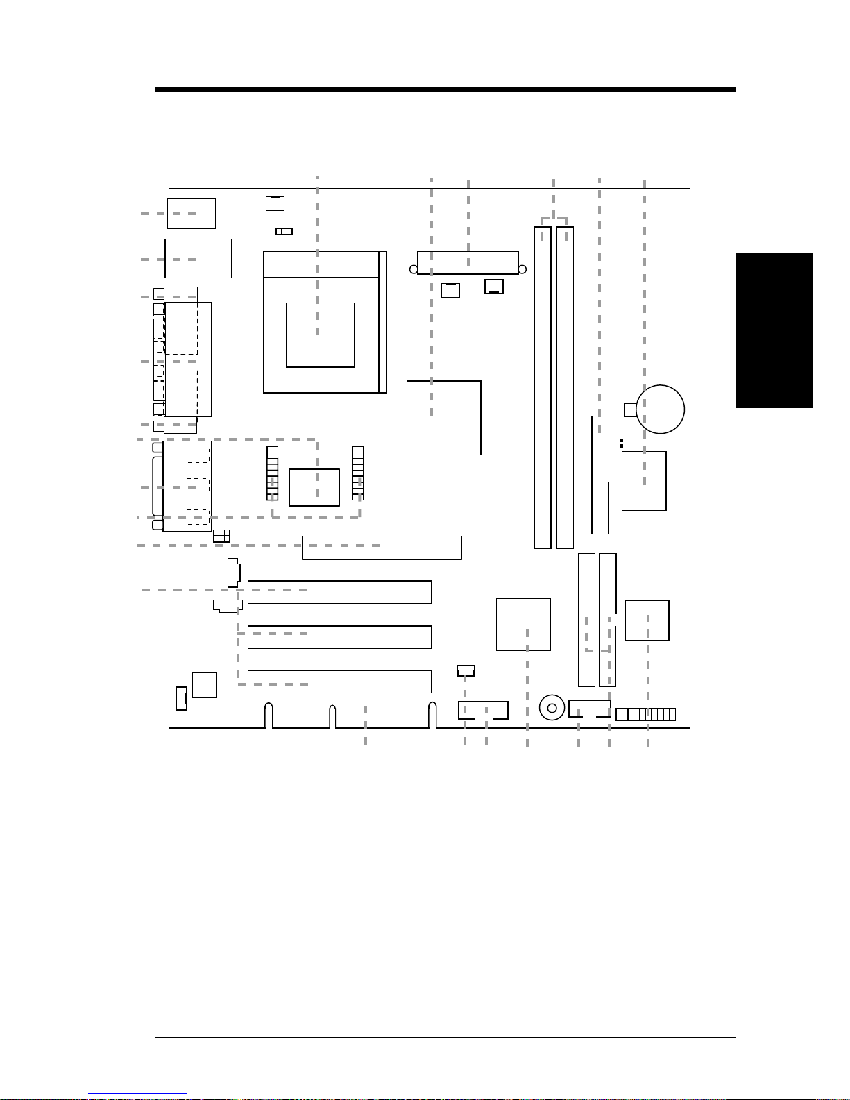
2.2 CUSL-L Motherboard Components
See opposite page for locations.
Location
Processor Support Socket A370 for Coppermine/Celeron (PPGA) Processors ..... 1
Chipsets Intel 815 Solano Graphics Memory Cont.Hub (GMCH) ......... 2
Intel I/O Controller Hub (ICH) ............................................. 10
4Mbit Firmware Hub (FWH) ................................................... 7
Low Pin Count SMC 47M102 SuperMulti-I/O Chipset .......... 6
Main Memory 2 DIMM Sockets (maximum 512MB support) ........................ 4
PC133 SDRAM support
Expansion Slots 1 PCI Extension Card golden finger....................................... 13
3 PCI Slots .............................................................................. 14
1 Universal Accelerated Graphics (AGP) Slot ....................... 15
System I/O 1 USB Header (2 Ports) .......................................................... 11
1 Floppy Disk Drive Connector ............................................... 5
2 IDE Connectors (UltraDMA33/66 Support) ......................... 8
1 Serial COM2 Header ............................................................. 9
1 Parallel Port Connector ............................................. (Top) 20
1 Serial COM1 Port Connector .............................. (Bottom) 21
2 USB Port Connectors .......................................... (Bottom) 22
1 PS/2 Mouse Connector ............................................. (Top) 23
1 PS/2 Keyboard Connector ................................... (Bottom) 23
3D Graphics Solano Integrated Graphics and Memory Controller Hub ....... 2
1 VGA Monitor Output Connector......................................... 19
TV-Out/Digital LCD Module Headers ................................... 16
Audio AC’97 V2.1 Audio Codec
1 Game/MIDI Connector) ............................................ (Top) 17
1 Speaker Out Connector ....................................... (Bottom) 17
1 Line In Connector................................................ (Bottom) 17
1 Microphone Connector ........................................ (Bottom) 17
Network Features Realtek 8139C PCI LAN Ethernet Controller ........................ 18
Wake-On-LAN Connector...................................................... 12
RJ-45 Connector ........................................................... (Top) 22
Power ATX Power Supply Connector ............................................... 31
Form Factor microATX
MB Components
2. FEATURES
Page 9
CUSL-L User’s Manual 9
2. FEATURES
2. FEATURES
MB Components
2.2.1 Component Locations
CUSL-L
34
14
11 710 8
15
17
19
20
21
22
23
18
1
5
9
12
26
13
16
Page 10
10
CUSL-L User’s Manual
3. HARDWARE SETUP
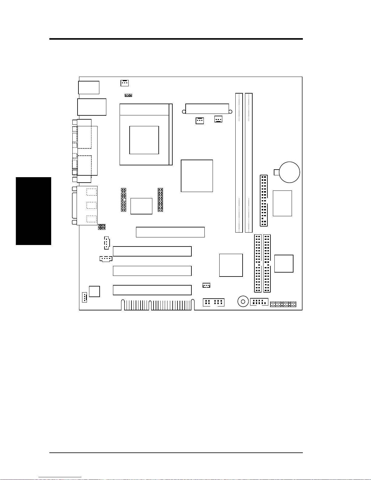
3.1 CUSL-L Motherboard Layout
PS/2KBMS
T: Mouse
B: Keyboard
PS_FAN
GAME_AUDIO
Mic
In
Line
Out
Line
In
PCI1
PANEL
FLOPPY
SECONDARY IDE
PRIMARY IDE
CUSL-L
CHA_FAN
CDIN
Accelerated Graphics Port (AGP)
CR2032 3V
Lithium Cell
CMOS Power
DIMM1 (64/72 bit, 168-pin module)
1
0
DIMM2 (64/72 bit, 168-pin module)
3
2
Socket 370
COM1
PARALLEL PORT
VGA
Audio
Codec
ATX Power Connector
CPU_FAN
MODEM
WOL_CON
LINEOUT_SW
COM2
ROW
LCDTV
Intel I/O
Controller
Hub
(ICH1)
Intel 815E
Graphics &
Memory
Controller
Hub (GMCH)
4Mbit
Firmware
Hub
(FWH)
USB
T: USB1
B: USB2
Top:
RJ-45
PCI3
PCI2
Fast
Ethernet
USB
CPUT
Multi
I/O
BUZZER
VIDEO
Grayed components are optional at the time of purchase.
Motherboard Layout
3. H/W SETUP
Page 11

CUSL-L User’s Manual 11
3. HARDWARE SETUP
3.2 Layout Contents
Expansion Slots
1) DIMM1/2 p.14 168-Pin System Memory Support
2) CPU p.15 Central Processing Unit (CPU)6
3) PCI1/2/3 p.16 32-bit PCI Bus Expansion Slots
4) PCI EX p.16 PCI Extension Card Golden Finger
5) AGP 4X p 17 Universal Accelerated Graphics Port (AGP) Slot
Connectors
1) PS2KBMS p.18 PS/2 Mouse Connector (6-pin female)
2) PS2KBMS p.18 PS/2 Keyboard Connector (6-pin female)
3) USB p.19 Universal Serial Bus Ports (Two 4-pin female)
4) PRINTER p.19 Parallel Port Connector (25-pin female)
5) COM1 p.20 Serial Port Connector (9-pin male, 10-1 pin)
6) VGA p.20 Monitor Output Connector (15-pin female)
7) GAME_AUDIO p.21 Game/MIDI Connector (15-pin female)
8) GAME_AUDIO p.21 Audio Port Connectors (Three 1/8” female)
9) RJ-45 p.21 Fast Ethernet Port Connector
10) FLOPPY p.22 Floppy Disk Drive Connector (34-1pins)
11) PRIMARY/SECONDAR Y IDE p.22 Primary/Secondary IDE Connectors (Two 40-1pins)
12) CPU_FAN, PS_FAN p.23 CPU, Power Supply , Chassis Fan Connectors (Three 3-pin)
CHA_FAN
13) CDIN, VIDEO, MODEM p.23 Internal Audio Connectors ( 4-pin CDIN, 4-pin
VIDEO MODEM)
14)WOL_CON p.24 Wake-On-LAN Connector (3 pins)
15) LCD-TV p.24 LCD-TV Headers (20-1 pins/20 pins)
16) CPUT p.24 CPU Thermal Sensor Connector (3-pin CPUT)
17) USB2 p.25 USB Headers (12-1 pins)
18) ATXPWR p.25 ATX Power Supply Connector (20 pins)
19) PLED (PANEL) p.26 System Power LED Lead (3-1 pins)
20) KLCK (PANEL) p.26 Keyboard Lock Switch Lead (2 pins)
21) SPEAKER (PANEL) p.26 System Warning Speaker Connector (4 pins)
22) IDELED p.26 IDE Activity LED (2-pin)
23) MLED (PANEL) p.26 System Message LED (2 pins)
24) SMI (PANEL) p.26 System Management Interrupt Switch Lead (2 pins)
25) PWR (PANEL) p.26 ATX Power / Soft-Off Switch Lead (2 pins)
26) RESET (PANEL) p.26 Reset Switch Lead (2 pins)
Layout Contents
3. H/W SETUP
Page 12

12 CUSL-L User’s Manual
3. HARDWARE SETUP
Set-up Procedure
3. H/W SETUP
3.3 Hardware Setup Procedure
Before using your computer, you must complete the following steps:
• Install Memory Modules
• Install the Central Processing Unit (CPU)
• Install Expansion Cards
• Connect Ribbon Cables, Panel Wires, and Power Supply
WARNING! Computer motherboards and expansion cards contain very delicate
Integrated Circuit (IC) chips. To protect them against damage from static electricity, you should follow some precautions whenever you work on your computer.
1. Unplug your computer when working on the inside.
2. Use a grounded wrist strap before handling computer components. If you do
not have one, touch both of your hands to a safely grounded object or to a metal
object, such as the power supply case.
3. Hold components by the edges and try not to touch the IC chips, leads or connectors, or other components.
4. Place components on a grounded antistatic pad or on the bag that came with the
component whenever the components are separated from the system.
5. Ensure that the ATX power supply is switched off before you plug in or
remove the ATX power connector on the motherboard.
WARNING! Make sure that you unplug your power supply when adding or
removing system components. Failure to do so may cause severe damage to
your motherboard, peripherals, and/or components.
Page 13
CUSL-L User’s Manual 13
3. HARDWARE SETUP
3.4 System Memory (DIMM)
NOTE: No hardware or BIOS setup is required after adding or removing memory.
This motherboard uses only Dual Inline Memory Modules (DIMMs). Sockets are
available for 3.3Volt (power level) unbuffered Synchronous Dynamic Random Ac-
cess Memory (SDRAM). One side (with memory chips) of the DIMM takes up one
row on the motherboard.
Memory speed setup is recommended through SDRAM Configuration in 4.4.1
Chip Configuration.
NOTE: If the total installed memory exceeds 512MB, the system will hang during
startup.
3.4.1 General DIMM Notes
• For the system CPU bus to operate at 133MHz, use only PC133-compliant
DIMMs.
• Motherboards support SPD (Serial Presence Detect) DIMMs. This is the memory
of choice for best performance vs. stability.
• Single-sided DIMMs come in 16, 32, 64,128, 256MB; double-sided come in 32,
64, 128, 256, 512MB.
Install memory in any combination as follows:
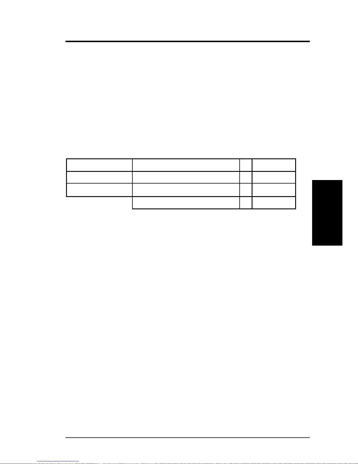
DIMM Location 168-pin DIMM Total Memory
Socket 1 (Rows 0&1) SDRAM 8, 16, 32, 64, 128, 256, 512MB x1
Socket 2 (Rows 2&3) SDRAM 8, 16, 32, 64, 128, 256, 512MB x1
Total System Memory (Max 512MB) =
System Memory
3. H/W SETUP
Page 14
14 CUSL-L User’s Manual
3. HARDWARE SETUP
3.4.2 Memory Installation
WARNING! Make sure that you unplug your power supply when adding or
removing memory modules or other system components. Failure to do so may
cause severe damage to both your motherboard and expansion cards (see 3.3
Hardware Setup Procedure for more information).
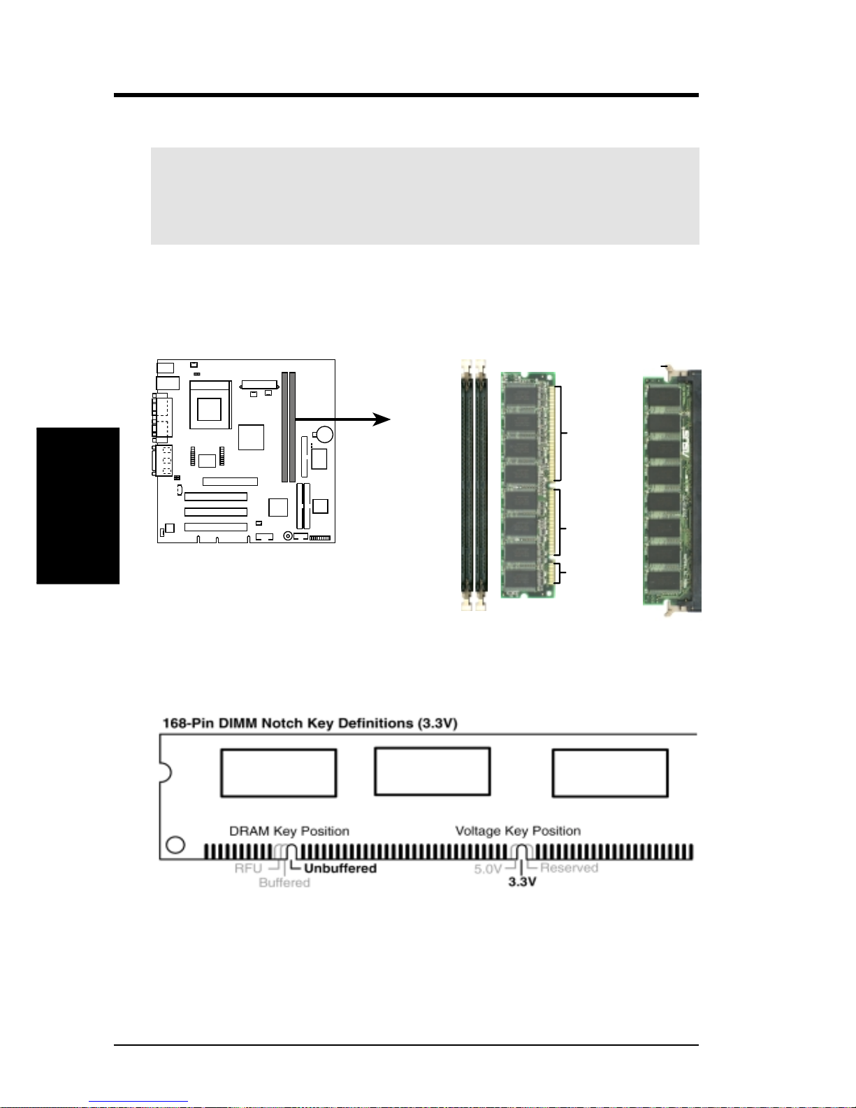
Insert the module(s) as shown. Because the number of pins are different on either
side of the breaks, the module will only fit in the orientation shown. DRAM SIMM
modules have the same pin contacts on both sides. SDRAM DIMMs have different
pin contacts on each side and therefore have a higher pin density.
CUSL-L
CUSL-L 168-Pin DIMM Sockets
Lock
20 Pins
60 Pins
88 Pins
The DIMMs must be 3.3Volt unbuffered SDRAMs. To determine the DIMM type,
check the notches on the DIMMs (see figure below).
The notches on the DIMM will shift between left, center, or right to identify the type
and also to prevent the wrong type from being inserted into the DIMM slot on the
motherboard. You must tell your retailer the correct DIMM type before purchasing.
This motherboard supports four clock signals per DIMM.
System Memory
3. H/W SETUP
Page 15
CUSL-L User’s Manual 15
3. HARDWARE SETUP
CPU
3. H/W SETUP
3.5 Central Processing Unit (CPU)
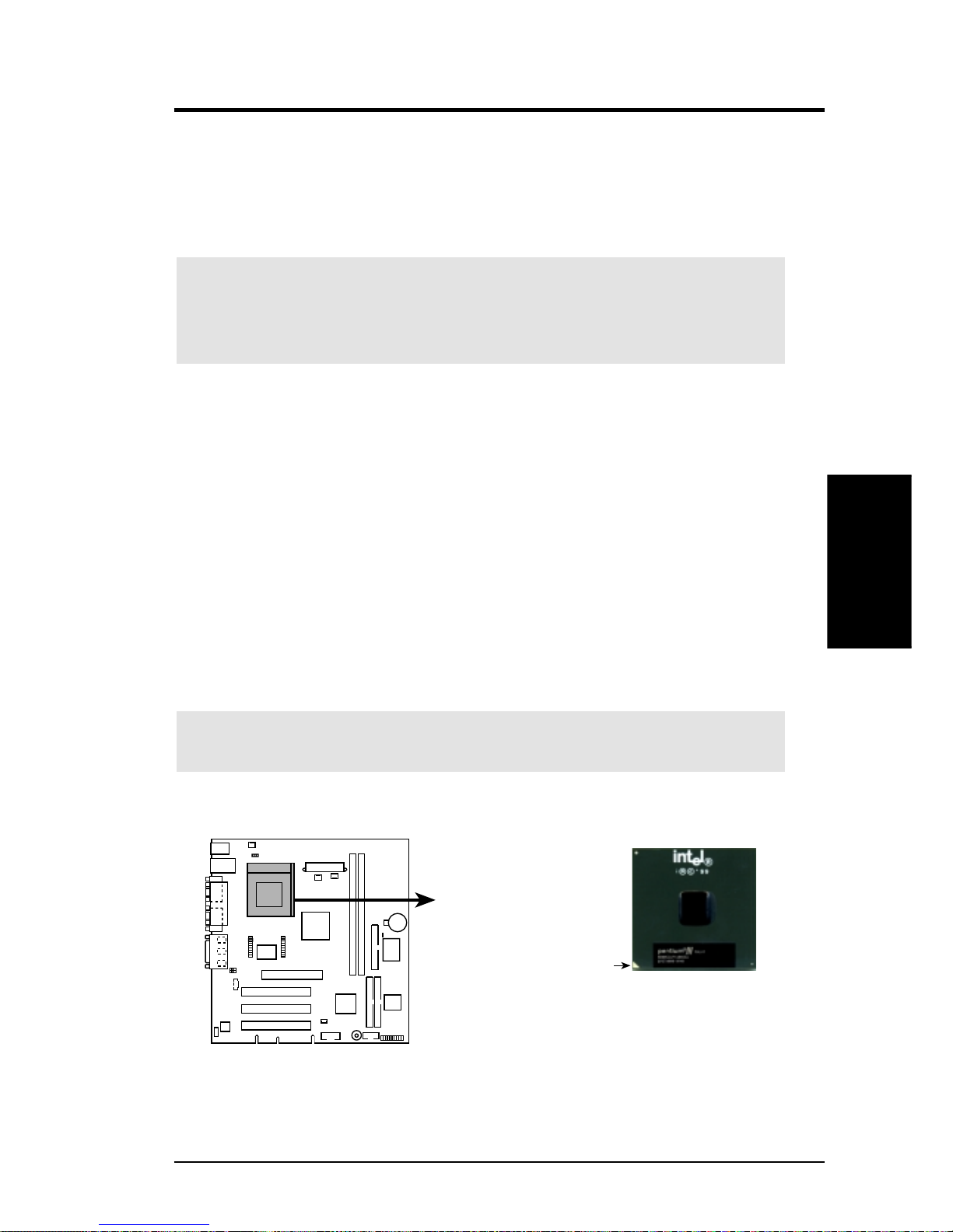
The motherboard provides a ZIF Socket 370. The CPU that came with the motherboard should have a fan attached to prevent overheating. If this is not the case, then
purchase a fan before turning on your system.
WARNING! Be sure that there is suf ficient air circulation across the processor’s
heatsink by regularly checking that your CPU fan is working. W ithout sufficient
circulation, the processor could overheat and damage both the processor and the
motherboard. You may install an auxiliary fan, if necessary.
To install a CPU, first turn off your system and remove its cover. Locate the ZIF
socket and open it by first pulling the lever sideways away from the socket then
upwards to a 90-degree angle. Insert the CPU with the correct orientation as shown.
The notched corner should point towards the end of the lever . Because the CPU has
a corner pin for two of the four corners, the CPU will only fit in the orientation as
shown. You should have a CPU fan that covers the face of the CPU. W ith the added
weight of the CPU fan, no force is required to insert the CPU. Once completely
inserted, close the socket’s lever while holding down the CPU. After the CPU is in
place, install an Intel recommended fan heatsink. Locate the CPU fan connector
(see 3.1 Motherboard Layout or 3.7 External Connectors) and connect the CPU
fan cable to it.
NOTE: Socket 370 processors provide internal thermal sensing so that a socket
mounted thermal resistor is not needed.
CAUTION! Be careful not to scrape the motherboard when mounting a clamp-
style processor fan or else damage may occur to the motherboard.
CUSL-L
CUSL-L Socket 370
Gold Arrow
Pentium III
Page 16
CUSL-L User’s Manual 15
3. HARDWARE SETUP
3.5 Central Processing Unit (CPU)
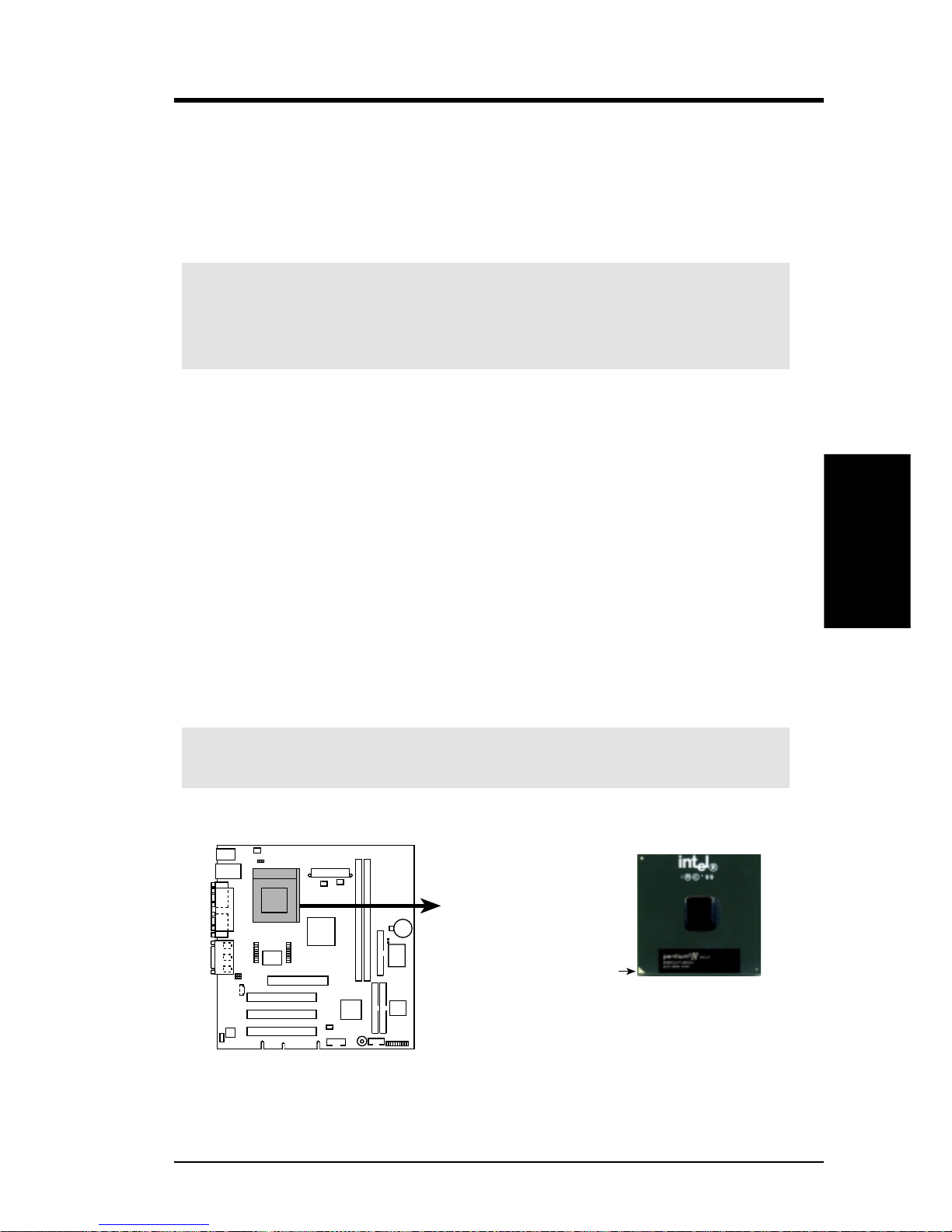
The motherboard provides a ZIF Socket 370. The CPU that came with the motherboard should have a fan attached to prevent overheating. If this is not the case, then
purchase a fan before turning on your system.
WARNING! Be sure that there is suf ficient air circulation across the processor’s
heatsink by regularly checking that your CPU fan is working. W ithout sufficient
circulation, the processor could overheat and damage both the processor and the
motherboard. You may install an auxiliary fan, if necessary.
To install a CPU, first turn off your system and remove its cover. Locate the ZIF
socket and open it by first pulling the lever sideways away from the socket then
upwards to a 90-degree angle. Insert the CPU with the correct orientation as shown.
The notched corner should point towards the end of the lever . Because the CPU has
a corner pin for two of the four corners, the CPU will only fit in the orientation as
shown. You should have a CPU fan that covers the face of the CPU. W ith the added
weight of the CPU fan, no force is required to insert the CPU. Once completely
inserted, close the socket’s lever while holding down the CPU. After the CPU is in
place, install an Intel recommended fan heatsink. Locate the CPU fan connector
(see 3.1 Motherboard Layout or 3.7 External Connectors) and connect the CPU
fan cable to it.
NOTE: Socket 370 processors provide internal thermal sensing so that a socket
mounted thermal resistor is not needed.
CAUTION! Be careful not to scrape the motherboard when mounting a clamp-
style processor fan or else damage may occur to the motherboard.
CUSL-L
CUSL-L Socket 370
Gold Arrow
Pentium III
CPU
3. H/W SETUP
Page 17
16 CUSL-L User’s Manual
3. HARDWARE SETUP
Expansion Cards
3. H/W SETUP
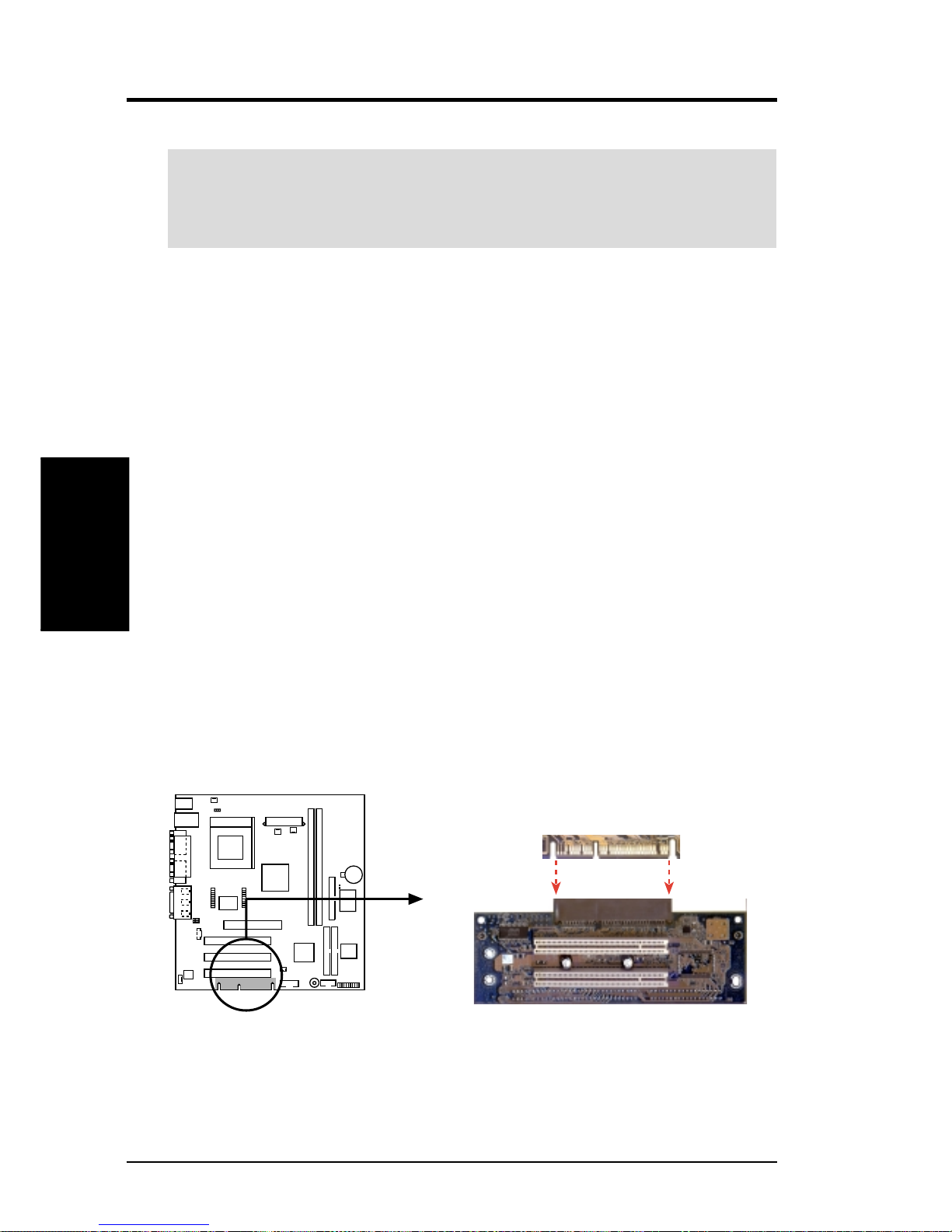
CUSL-L PCI Extension Card
CUSL-L
3.6 Expansion Cards
WARNING! Unplug your power supply when adding or removing expansion
cards or other system components. Failure to do so may cause severe damage to
both your motherboard and expansion cards (see 3.3 Hardware Setup Proce-
dure for more information).
3.6.1 PCI Expansion Card Installation Procedure
1. Read the documentation for your expansion card and make any necessary hardware or software settings for your expansion card, such as jumpers.
2. Remove your computer system’s cover and the bracket plate on the slot you
intend to use. Keep the bracket for possible future use.
3. Carefully align the card’s connectors and press firmly.
4. Secure the card on the slot with the screw you removed above.
5. Replace the computer system’s cover.
6. Set up the BIOS if necessary
7. Install the necessary software drivers for your expansion card.
3.6.2 PCI Extension Card Golden Finger
This motherboard features a plug-in extension “golden finger” configured to support two PCI slots. An extension board plugs into the built-in golden finger on the
edge of the motherboard. The golden finger only supports one PCI extension board;
do not attempt to use other extenders or cards of any kind on the golden finger.
Page 18
CUSL-L User’s Manual 17
3. HARDWARE SETUP
Expansion Cards
3. H/W SETUP
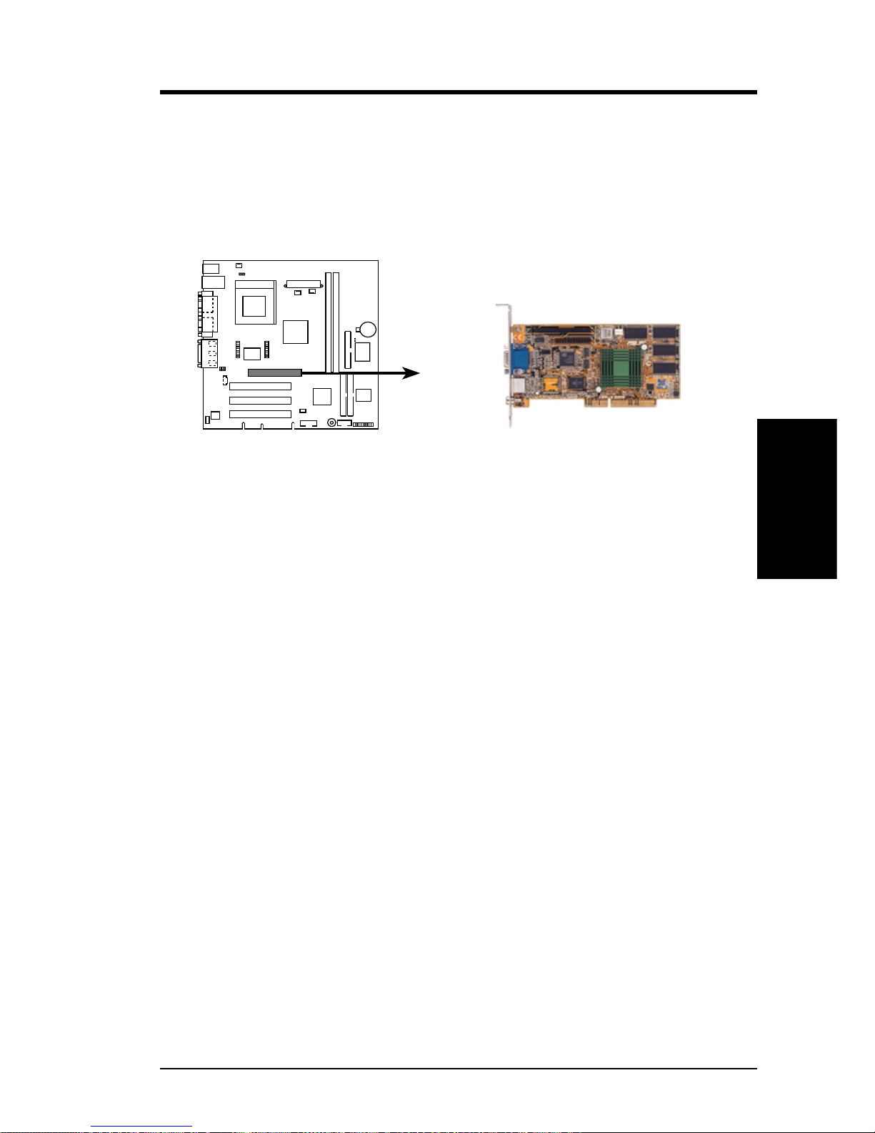
3.6.3 Universal Accelerated Graphics (AGP) 4X Port
This motherboard provides an accelerated graphics port (AGP) slot to support a
universal AGP 4X graphics cards with ultra-high memory bandwidth. This slot can
also support an AGP Inline Memory Module (AIMM) for up to 4MB of 133MHz
SDRAM display cache to work with the integrated graphics controller to deliver
high quality video graphics.
CUSL-L Accelerated Graphics Port (AGP)
CUSL-L
NOTE: Disable the integrated graphics controller (see Onboard VGA in BIOS)
when using an add-on graphics card.
Page 19
18 CUSL-L User’s Manual
3. HARDWARE SETUP
Expansion Cards
3. H/W SETUP
3.7 External Connectors
WARNING! Some pins are used for connectors or power sources. These are
clearly distinguished from jumpers in the Motherboard Layout. Placing jumper
caps over these connector pins will cause damage to your motherboard.
IMPORTANT: Ribbon cables should always be connected with the red stripe to
Pin 1 on the connectors. Pin 1 is usually on the side closest to the power connector on hard drives and CD-ROM drives, but may be on the opposite side on
floppy disk drives. Check the connectors before installation because there may
be exceptions. IDE ribbon cable must be less than 46 cm (18 in.), with the second drive connector no more than 15 cm (6 in.) from the first connector.
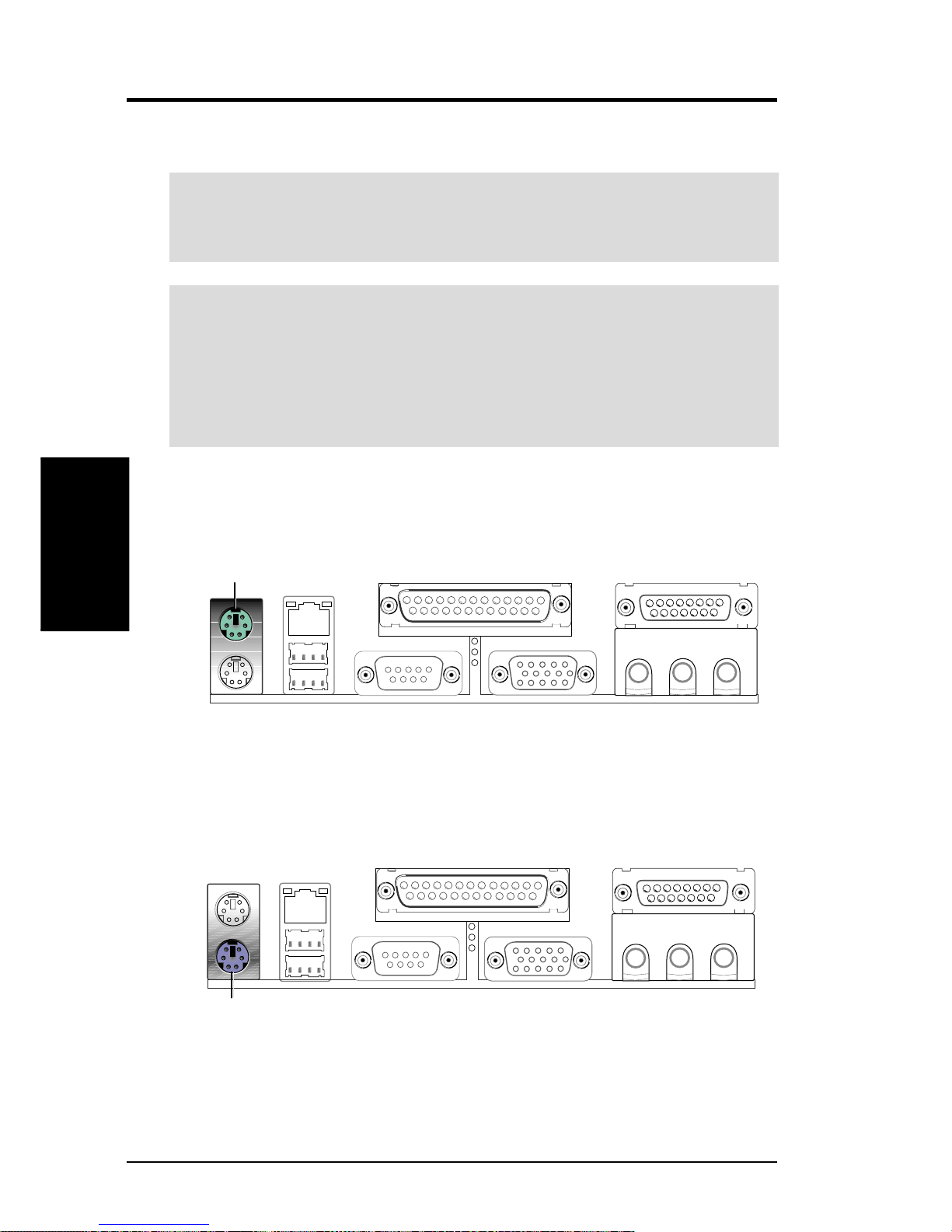
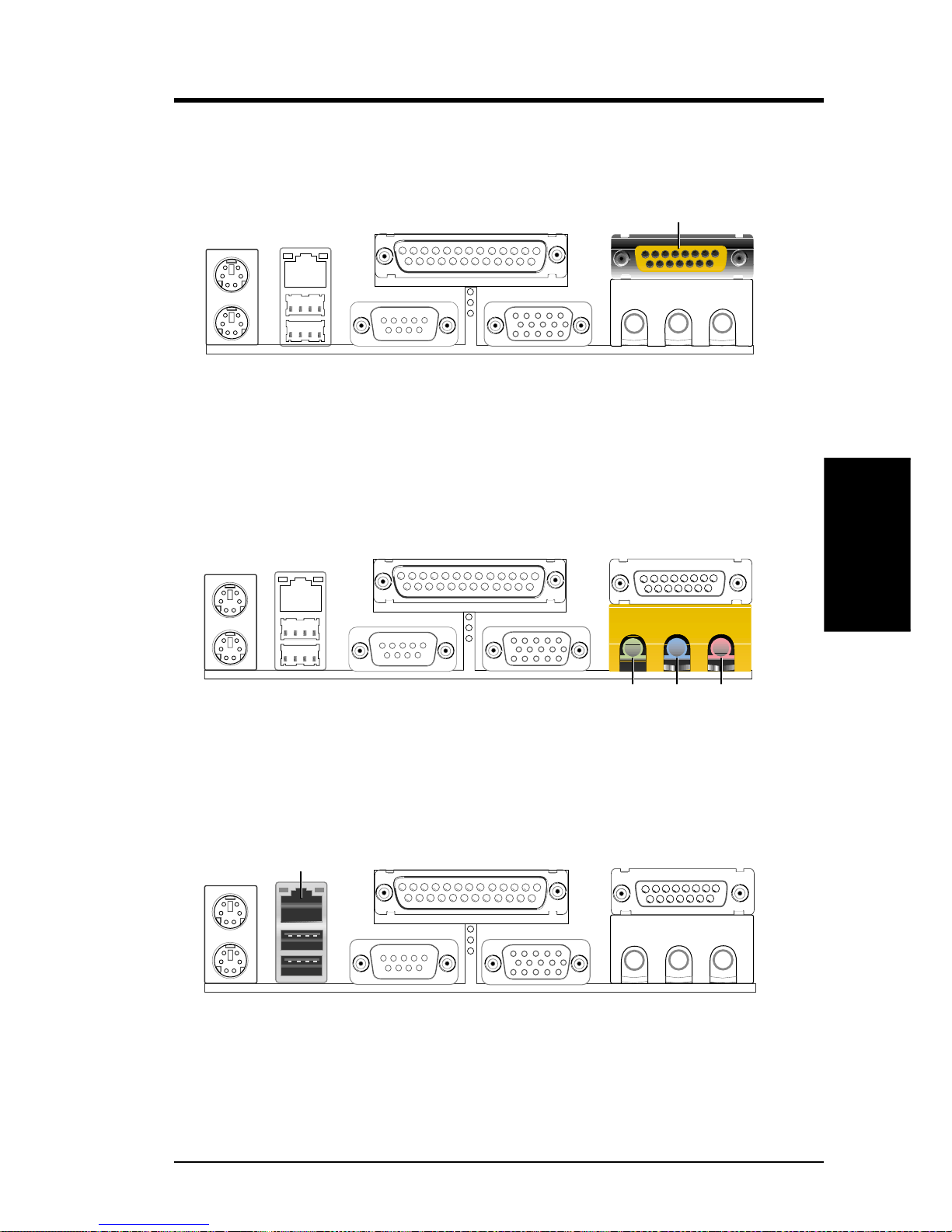
1) PS/2 Mouse Connector (Green 6-pin PS2KBMS)
The system will direct IRQ12 to the PS/2 mouse if one is detected.
PS/2 Mouse (6-pin female)
2) PS/2 Keyboard Connector (Purple 6-pin PS2KBMS)
This connection is for a standard keyboard using an PS/2 plug (mini DIN). This
connector will not allow standard AT size (large DIN) keyboard plugs. You
may use a DIN to mini DIN adapter on standard AT keyboards.
PS/2 Keyboard (6-pin female)
Page 20
CUSL-L User’s Manual 19
3. HARDWARE SETUP
Connectors
3. H/W SETUP
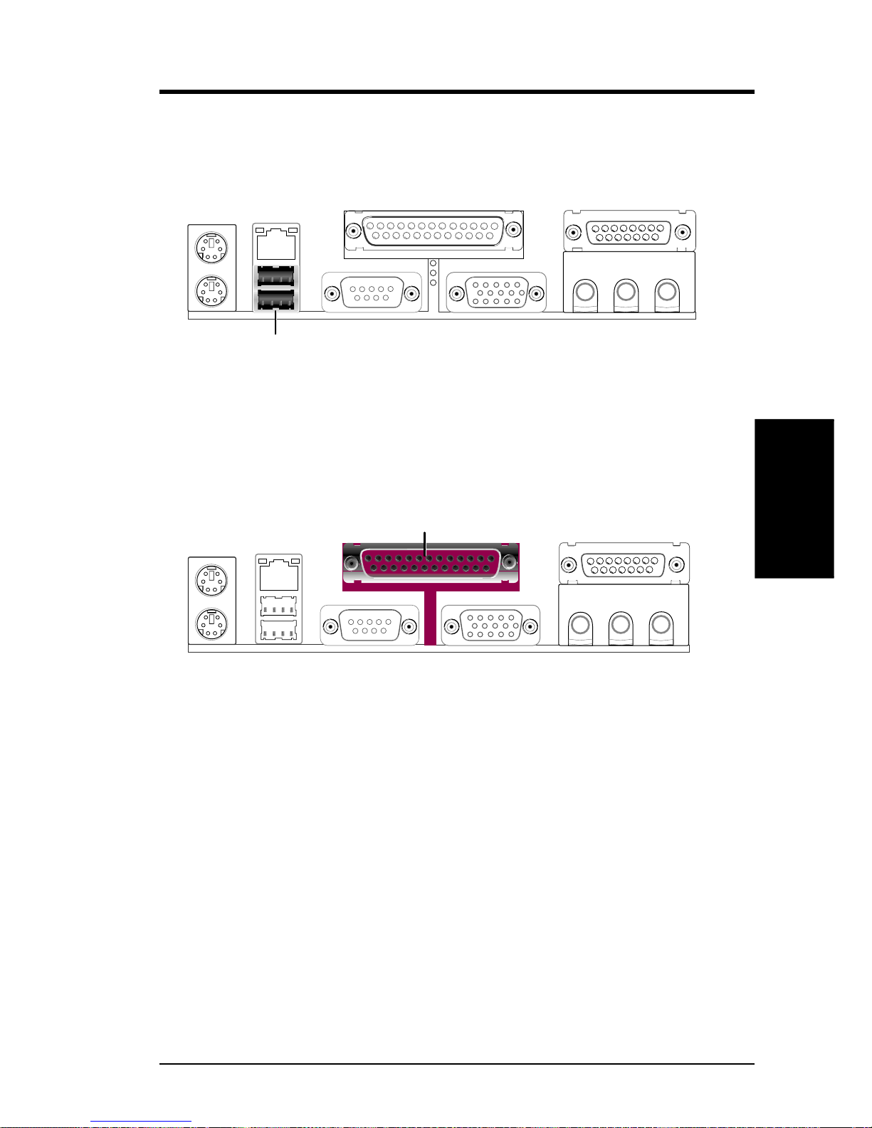
3) Universal Serial BUS Ports 0 & 1 (Black two 4-pin USB)
Two USB ports are available for connecting USB devices. For additional USB
ports, you can use the USB headers (see USB Headers later in this section) and
mount new ports to the chassis.
Universal Serial Bus (USB)
4) Parallel Port Connector (Burgundy 25-pin PRINTER)
Enable the parallel port and choose the IRQ through Onboard Parallel Port
command.
NOTE: Serial printers must be connected to the serial port.
Parallel (Printer) Port (25-pin female)
Page 21
20 CUSL-L User’s Manual
Connectors
3. H/W SETUP
3. HARDWARE SETUP
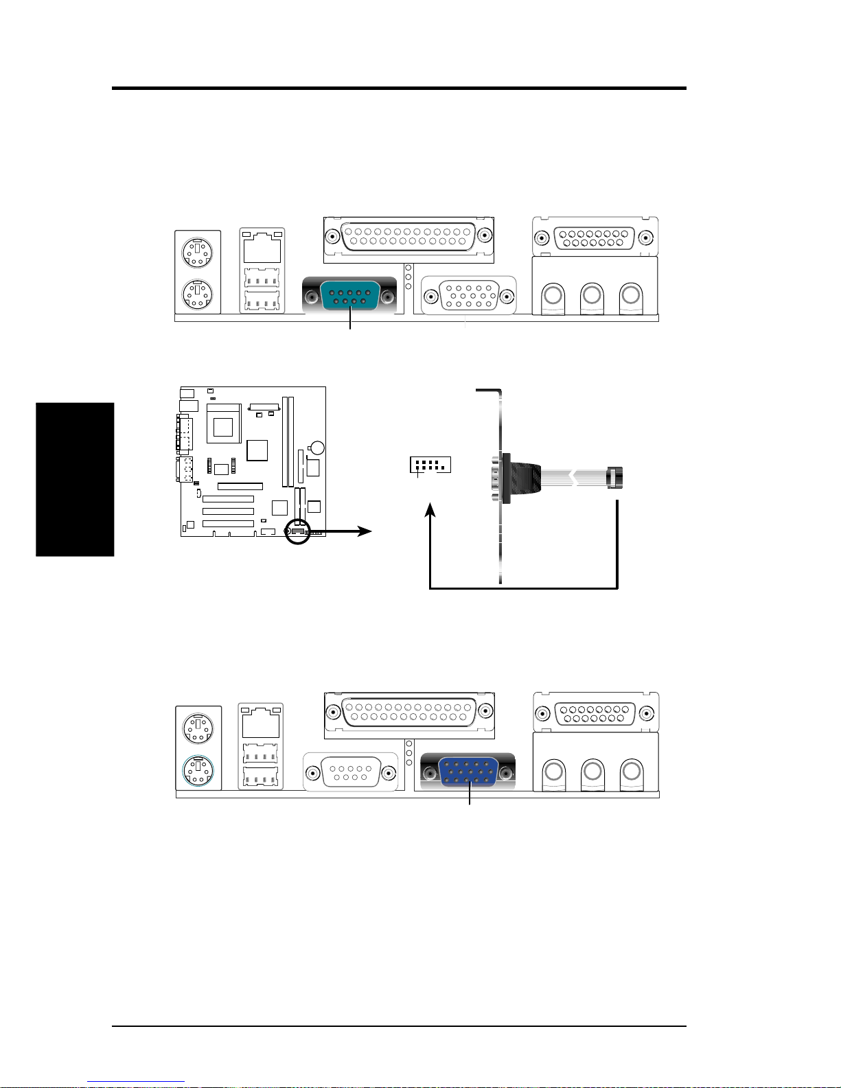
5) Serial Port Connectors (Teal/Turquoise 9-pin COM1, 10-1 pin COM2)
One serial port is ready for a mouse or other serial devices. A second serial port
is available using a serial port bracket connected from the motherboard to an
expansion slot opening.
COM 1
Serial Port (9-pin male)
CUSL-L Serial COM2 Bracket
PIN 1
CUSL-L
6) Monitor Output Connector (Blue 15-pin VGA)
This connector is for output to a VGA-compatible device.
VGA Monitor (15-pin female)
Page 22
CUSL-L User’s Manual 21
3. HARDWARE SETUP
Connectors
3. H/W SETUP
7) Game/MIDI Connector (Gold 15-pin GAME_AUDIO)
You may connect game joysticks or game pads to this connector for playing
games. Connect MIDI devices for playing or editing professional audio.
Game/MIDI (15-pin female)
8) Audio Port Connectors (Three 1/8” GAME_AUDIO)
Speaker (orange) can be connected to headphones or preferably powered speak-
ers. Line In (light blue) allows tape players or other audio sources to be re-
corded by your computer or played through the Speaker (orange). Mic (pink)
allows microphones to be connected for inputting voice.
MicLine InLine Out
1/8" Stereo Audio Connectors
9) Fast-Ethernet Port Connector (RJ-45)
The RJ-45 connector is optional at the time of purchase and is located on top of
the USB connectors. The connector allows the motherboard to connect to a Local Area Network (LAN) through a network hub.
RJ45
Page 23
22 CUSL-L User’s Manual
Connectors
3. H/W SETUP
3. HARDWARE SETUP
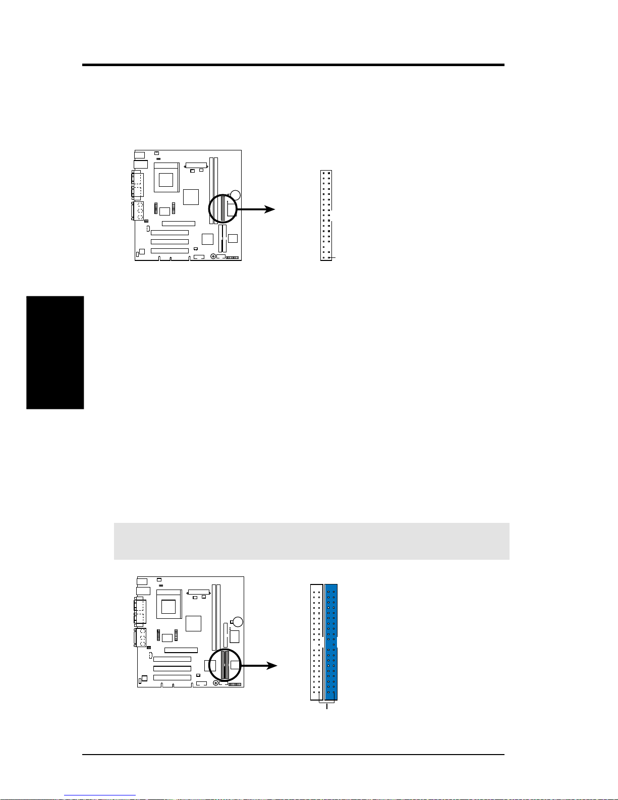
11) Primary (Blue) / Secondary IDE Connectors (Two 40-1pin IDE)
These connectors support the IDE hard disk ribbon cable supplied with this
motherboard. Connect the cable’s blue connector to the motherboard’s primary
(recommended) or secondary IDE connector, and then connect the gray connector to your UltraDMA/66 slave device (hard disk drive) and the black connector
to your UltraDMA/66 master device. It is recommended that non-UltraDMA/66
devices be connected to the secondary IDE connector. If you install two hard
disks, you must configure the second drive to Slave mode by setting its jumper
accordingly. Please refer to your hard disk documentation for the jumper settings. BIOS now supports specific device bootup. (Pin 20 is removed to pre-
vent inserting in the wrong orientation when using ribbon cables with pin
20 plugged).
TIP: You may configure two hard disks to be Masters with two ribbon cables –
one for the primary IDE connector and another for the secondary IDE connector. You may install one operating system on an IDE drive and another on a
SCSI drive and select the boot disk through CMOS Setup in device firmware.
IMPORTANT: UltraDMA/66 IDE devices must use a 40-pin 80-conductor IDE
cable for 66 MByte/sec transfer rates.
CUSL-L
CUSL-L IDE Connectors
NOTE: Orient the red markings
(usually zigzag) on the IDE
ribbon cable to PIN 1.
Secondary IDE Connector
PIN 1
Primary IDE Connector
10) Floppy Disk Drive Connector (34-1pin FLOPPY)
This connector supports the provided floppy drive ribbon cable. After connecting the single end to the board, connect the two plugs on the other end to the
floppy drives. (Pin 5 is removed to prevent inserting in the wrong orienta-
tion when using ribbon cables with pin 5 plugged).
CUSL-L
NOTE: Orient the red markings on
the floppy ribbon cable to PIN 1.
CUSL-L Floppy Disk Drive Connector
PIN 1
FLOPPY
Page 24
CUSL-L User’s Manual 23
3. HARDWARE SETUP
Connectors
3. H/W SETUP
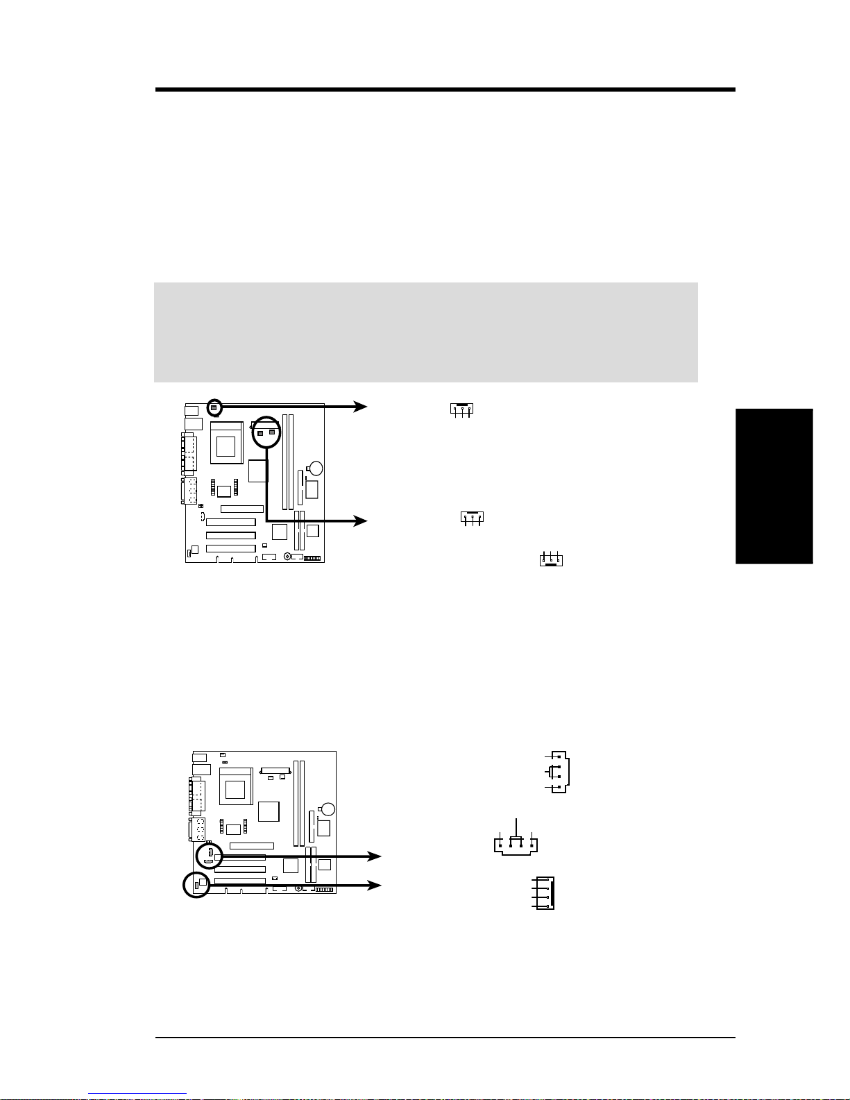
12) Power Supply (PS_FAN), CPU (CPU_FAN), Chassis (CHA_FAN) Fan
Connectors (3 pins)
These connectors support cooling fans of 350mA (4.2 Watts) or less. Orientate
the fans so that the heat sink fins allow airflow to go across the onboard heat
sink(s) instead of the expansion slots. Depending on the fan manufacturer, the
wiring and plug may be different. The red wire should be positive, while the
black should be ground. Connect the fan’s plug to the board taking into consid-
eration the polarity of the connector.
WARNING! The CPU and/or motherboard will overheat if there is no airflow
across the CPU and onboard heatsinks. Damage may occur to the motherboard
and/or the CPU fan if these pins are incorrectly used. These are not jumpers,
do not place jumper caps over these pins.
CUSL-L
CUSL-L 12-Volt Cooling Fan Power
CPU_FAN
PS_FAN
CHA_FAN
GND
Rotation
+12V
GND
Rotation
+12V
GND
GND
Fanstop
13) Internal Audio Connectors (4-pin CD1N, MODEM)
These connectors allow you to receive stereo audio input from such sound sources
as a CD-ROM, TV tuner, or MPEG card. The MODEM connector allows the
onboard audio to interface with a voice modem card with a similar connector.
CUSL-L Internal Audio Connectors
MODEM
VIDEO (Green)
Modem-Out
Ground
Modem-In
Ground
CUSL-L
CDIN (Black)
Right Audio Channel
Left Audio Channel
Ground
Right Audio Channel
Left Audio Channel
Ground
Page 25
24 CUSL-L User’s Manual
Connectors
3. H/W SETUP
3. HARDWARE SETUP
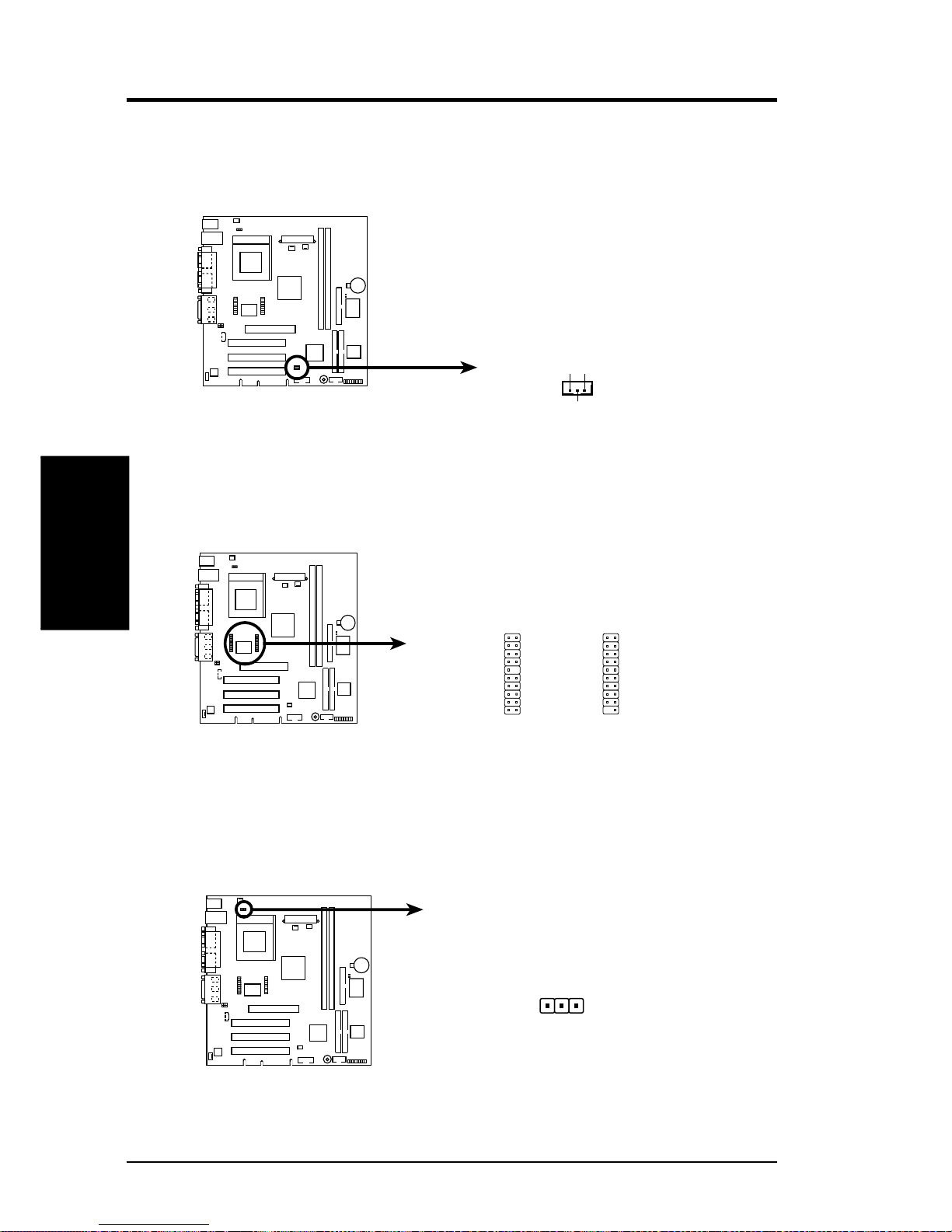
14) Wake-On-LAN Connector (3-pin WOL_CON)
This connector links a LAN card with a Wake-On-LAN output. The connector
powers up the system when a wakeup signal is received through the LAN card.
CUSL-L
CUSL-L Wake-On-LAN Connector
IMPORTANT: Requires an ATX power
supply with at least 720mA +5 volt
standby power
+5 Volt Standby
PME
Ground
WOL_CON
15) LCD-TV Headers (20-pin, 20-1 pin LCDTV)
These headers require an optional LCD module for LCD output or a TV-out
module for TV output.
CUSL-L
CUSL-L LCD-TV Headers
1
LCDTV
16) CPU Thermal Sensor Connector (3-pin CPUT)
This connector requires a thermal sensor device to be attached to the surface of
the CPU for thermal monitoring and response.
CUSL-L
CUSL-L Thermal Sensor Connector
CPUT
Page 26
CUSL-L User’s Manual 25
3. HARDWARE SETUP
Connectors
3. H/W SETUP
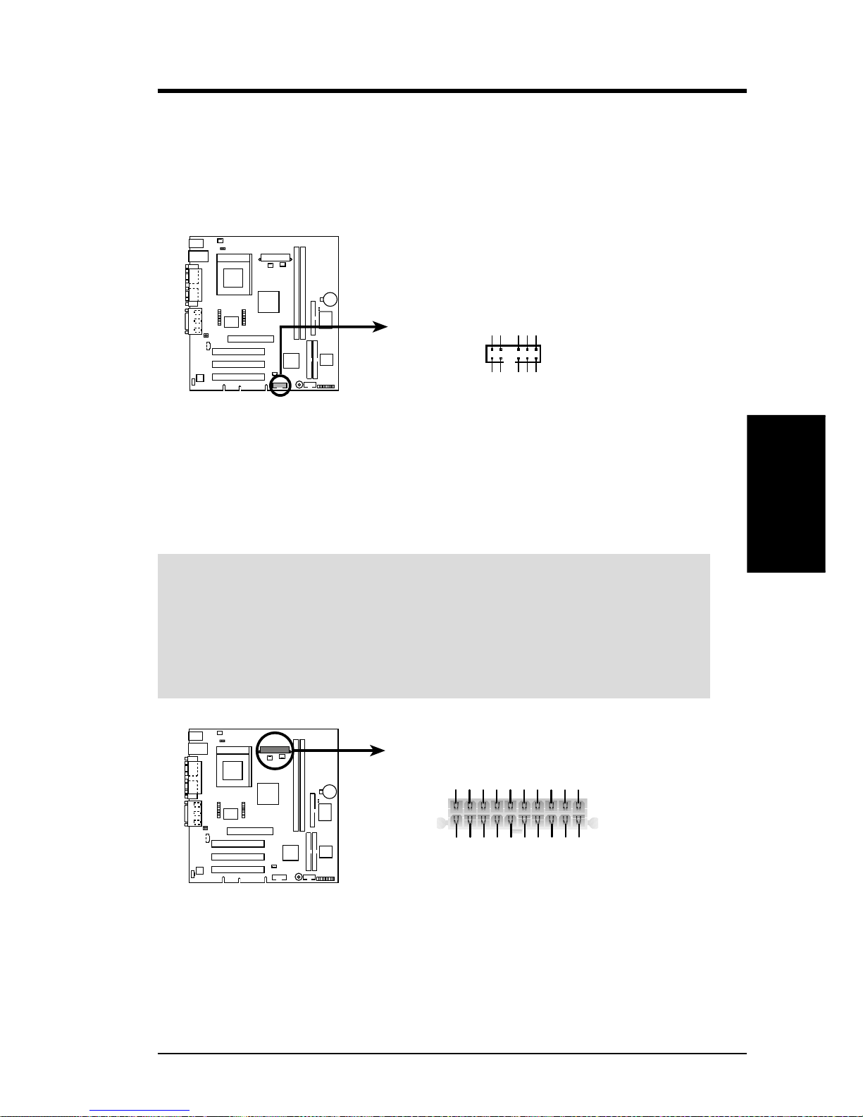
17) USB Headers (12-1 pin USB2)
If the USB Ports on the back panels are inadequate, a USB header is available
for two additional USB ports. Connect the 12-1 pin ribbon cable from the provided 2-port USB connector set to the midboard 12-1 pin USB header and mount
the USB connector set to an open slot on your chassis.
CUSL-L
CUSL-L USB Header
USBPORT
1
2
11
12
GND
GND
GNDGND
USBP–
USBP–
USBP+
USBP+
USB PowerUSB Power
18) ATX Power Supply Connector (20-pin block ATXPWR)
This connector connects to an ATX power supply. The plug from the power supply will only insert in one orientation because of the different hole sizes. Find the
proper orientation and push down firmly making sure that the pins are aligned.
IMPORTANT: Make sure that your A TX power supply (minimum recommended
wattage: 200 watts; 235W for a fully-configured system) can supply at least 20
amperes on the +5-volt lead and at least 10mA (750mA recommended) on the +5volt standby lead (+5VSB). Your system may become unstable/unreliable and may
experience difficulty in powering up if your power supply is inadequate. For W akeOn-LAN support, your ATX power supply must supply at least 750mA +5VSB.
CUSL-L ATX Power Connector
+3.3 Volts
-12.0 Volts
Ground
Power Supply On
Ground
Ground
Ground
-5.0 Volts
+5.0 Volts
+5.0 Volts
Power Good
+12.0 Volts
+3.3 Volts
+3.3 Volts
Ground
+5.0 Volts
Ground
+5.0 Volts
Ground
+5V Standby
CUSL-L
Page 27
26 CUSL-L User’s Manual
Connectors
3. H/W SETUP
3. HARDWARE SETUP
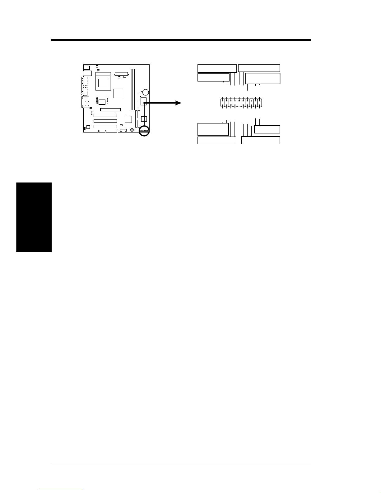
19) System Power LED Lead (3-1 pin PLED)
This 3-1 pin connector connects the system power LED, which lights when the
system is powered on and blinks when it is in sleep mode.
20) Keyboard Lock Switch Lead (2-pin KLCK)
A 2-pin connector to the case-mounted key switch for keyboard locking.
21) System Warning Speaker Connector (4-pin SPEAKER)
This 4-pin connector connects to the case-mounted speaker. Two sources
(LINE_OUT and SPEAKER) will allow you to hear system beeps and warnings. Only SPEAKER will allow you to hear system beeps before the integrated
audio has been properly initialized.
22) IDE Activity LED (2-pin IDELED)
This connector supplies power to the cabinet’s IDE activity LED. Read and
write activity by devices connected to the Primary or Secondary IDE connectors
will cause the LED to light up.
23) System Message LED Lead (2-pin MLED)
This indicates whether a message has been received from a fax/modem. The
LED will remain lit when there is no signal and blink when there is data received. This function requires an ACPI OS and driver support.
24) System Management Interrupt Lead (2-pin SMI)
This allows the user to manually place the system into a suspend mode or “Green”
mode, where system activity is decreased to save electricity and expand the life
of certain components when the system is not in use. This 2-pin connector connects to the case-mounted suspend switch.
25) ATX Power Switch Lead (2-pin PWR)
The system power is controlled by a momentary switch connected to this lead.
Pressing the button once will switch the system between ON and SOFT OFF.
Pushing the switch while in the ON mode for more than 4 seconds will turn the
system off. The system power LED shows the status of the system’s power.
26) Reset Switch Lead (RESET)
Pressing the reset button restarts the computer if a system freeze-up occurs.
CUSL-L
CUSL-L System Panel Connectors
*
Requires an ATX power supply.
IDELED-
Keylock
+5V
Speaker
Speaker
Connector
Power LED
Ground
Reset SW
IDELED
Message LED
ExtSMI#
Reset Ground
Ground
Keyboard Lock
ATX Power
Switch*
PWRBTN
Ground
IDELED+
PWRLED+
PWRLED-
PWRLEDB-
MSGLED+
MSGLED-
Ground
SMI Lead
The following diagram is for items 19-25
 Loading...