

Page 1

®
CUPLE-VM
JumperFree™ PC133/VC133
133/100/66 MHz FSB
Socket 370 Motherboard
USER’S MANUAL
Page 2

USER'S NOTICE
No part of this manual, including the products and software described in it, may be reproduced,
transmitted, transcribed, stored in a retrieval system, or translated into any language in any form
or by any means, except documentation kept by the purchaser for backup purposes, without the
express written permission of ASUSTeK COMPUTER INC. (“ASUS”).
ASUS PROVIDES THIS MANUAL “AS IS” WITHOUT WARRANTY OF ANY KIND, EITHER EXPRESS OR IMPLIED, INCLUDING BUT NOT LIMITED T O THE IMPLIED WARRANTIES OR CONDITIONS OF MERCHANTABILITY OR FITNESS FOR A PARTICULAR
PURPOSE. IN NO EVENT SHALL ASUS, ITS DIRECTORS, OFFICERS, EMPLOYEES OR
AGENTS BE LIABLE FOR ANY INDIRECT, SPECIAL, INCIDENTAL, OR CONSEQUENTIAL DAMAGES (INCLUDING DAMAGES FOR LOSS OF PROFITS, LOSS OF BUSINESS,
LOSS OF USE OR DA TA, INTERRUPTION OF BUSINESS AND THE LIKE), EVEN IF ASUS
HAS BEEN ADVISED OF THE POSSIBILITY OF SUCH DAMAGES ARISING FROM ANY
DEFECT OR ERROR IN THIS MANUAL OR PRODUCT.
Product warranty or service will not be extended if: (1) the product is repaired, modified or altered, unless such repair, modification of alteration is authorized in writing by ASUS; or (2) the
serial number of the product is defaced or missing.
Products and corporate names appearing in this manual may or may not be registered trademarks
or copyrights of their respective companies, and are used only for identification or explanation
and to the owners’ benefit, without intent to infringe.
• VIA and KT133 are trademarks of VIA Technologies, Inc.
• AMD, Athlon™ are trademarks of Advanced Micro Devices, Inc.
• Windows and MS-DOS are registered trademarks of Microsoft Corporation.
• Adobe and Acrobat are registered trademarks of Adobe Systems Incorporated.
• Trend and ChipAwayVirus are trademarks of Trend Micro, Inc.
• Other company and product names may be trademarks or registered trademarks of the respective
companies with which they are associated.
The product name and revision number are both printed on the product itself. Manual revisions
are released for each product design represented by the digit before and after the period of the
manual revision number . Manual updates are represented by the third digit in the manual revision
number.
For previous or updated manuals, BIOS, drivers, or product release information, contact ASUS at
http://www .asus.com.tw or through any of the means indicated on the following page.
SPECIFICA TIONS AND INFORMATION CONTAINED IN THIS MANUAL ARE FURNISHED
FOR INFORMA TIONAL USE ONL Y, AND ARE SUBJECT TO CHANGE A T ANY TIME WITHOUT NOTICE, AND SHOULD NOT BE CONSTRUED AS A COMMITMENT BY ASUS. ASUS
ASSUMES NO RESPONSIBILITY OR LIABILITY FOR ANY ERRORS OR INACCURACIES THAT MAY APPEAR IN THIS MANUAL, INCLUDING THE PRODUCTS AND SOFTWARE DESCRIBED IN IT.
Copyright © 2001 ASUSTeK COMPUTER INC. All Rights Reserved.
Product Name: ASUS CUPLE-VM
Manual Revision: 1.00 E778
Release Date: June 2001
2
ASUS CUPLE-VM User’s Manual
Page 3

ASUS CONTACT INFORMATION
ASUSTeK COMPUTER INC. (Asia-Pacific)
Marketing
Address: 150 Li-Te Road, Peitou, Taipei, Taiwan 112
Telephone: +886-2-2894-3447
Fax: +886-2-2894-3449
Email: [email protected]
Technical Support
MB/Others (Tel): +886-2-2890-7121 (English)
Notebook (Tel): +886-2-2890-7122 (English)
Desktop/Server (Tel): +886-2-2890-7123 (English)
Fax: +886-2-2893-7775
Email: [email protected]
WWW: www.asus.com.tw
FTP: ftp.asus.com.tw/pub/ASUS
ASUS COMPUTER INTERNATIONAL (America)
Marketing
Address: 6737 Mowry Avenue, Mowry Business Center, Building 2
Technical Support
ASUS COMPUTER GmbH (Europe)
Marketing
Address: Harkortstr. 25, 40880 Ratingen, BRD, Germany
Fax: +49-2102-442066
Email: [email protected] (for marketing requests only)
Technical Support
Hotline: MB/Others: +49-2102-9599-0 Notebook: +49-2102-9599-10
Fax: +49-2102-9599-11
Support (Email): www.asuscom.de/de/support (for online support)
WWW: www.asuscom.de
FTP: ftp.asuscom.de/pub/ASUSCOM
ASUS CUPLE-VM User’s Manual 3
Page 4

CONTENTS
1. INTRODUCTION 7
1.1 How This Manual Is Organized................................................. 7
1.2 Item Checklist ............................................................................ 7
2. FEATURES 8
2.1 The ASUS CUPLE-VM............................................................. 8
2.1.1 Specifications.................................................................. 8
2.1.2 Special Features ............................................................ 10
2.1.3 Performance Features.................................................... 10
2.1.4 Intelligence.................................................................... 11
2.2 Motherboard Components ....................................................... 12
2.2.1 Component Locations ................................................... 13
3. HARDWARE SETUP 14
3.1 Motherboard Layout ................................................................ 14
3.2 Layout Contents ....................................................................... 15
3.3 Hardware Setup Procedure ...................................................... 16
3.4 Motherboard Settings............................................................... 16
3.5 System Memory (DIMM) ........................................................ 18
3.5.1 General DIMM Notes ................................................... 18
3.5.2 Memory Installation...................................................... 19
3.6 Central Processing Unit (CPU)................................................ 20
3.6.1 CPU Installation............................................................ 21
3.7 Expansion Cards ...................................................................... 22
3.7.1 Installing an Expansion Card ........................................ 22
3.7.2 Assigning IRQs for Expansion Cards ........................... 23
3.7.4 Advanced Modem Riser (AMR) Slot ........................... 24
3.8 External Connectors................................................................. 25
3.9 Starting Up the First Time ....................................................... 35
4. BIOS SETUP 37
4.1 Managing and Updating Your BIOS........................................ 37
4.1.1 Upon First Use of the Computer System ...................... 37
4.1.2 Updating BIOS Procedures........................................... 38
4.2 BIOS Setup Program ............................................................... 40
4.2.1 BIOS Menu Bar ............................................................ 41
4.2.2 Legend Bar.................................................................... 41
4
ASUS CUPLE-VM User’s Manual
Page 5

CONTENTS
4.3 Main Menu............................................................................... 43
4.3.1 Primary & Secondary Master/Slave.............................. 44
4.3.2 Keyboard Features ........................................................ 47
4.4 Advanced Menu ....................................................................... 49
4.4.1 Chip Configuration ....................................................... 51
4.4.2 I/O Device Configuration ............................................. 54
4.4.3 PCI Configuration......................................................... 58
4.4.4 Shadow Configuration .................................................... 62
4.5 Power Menu ............................................................................. 63
4.5.1 Power Up Control ......................................................... 65
4.5.2 Hardware Monitor......................................................... 67
4.6 Boot Menu ............................................................................... 68
4.7 Exit Menu ................................................................................ 70
5. SOFTWARE SETUP 73
5.1 Install Operating System.......................................................... 73
5.2 Start Windows.......................................................................... 73
5.3 CUPLE-VM Series Support CD .............................................. 74
6. SOFTWARE REFERENCE 75
6.1 ASUS PC Probe ....................................................................... 75
6.2 CyberLink PowerPlayer SE ..................................................... 80
6.3 CyberLink PowerDVD ............................................................ 80
6.4 CyberLink VideoLive Mail...................................................... 82
6.5 ASUS Update........................................................................... 84
6.6 Creative Audio ......................................................................... 85
7. APPENDIX 87
7.1 Glossary ................................................................................... 87
INDEX 91
ASUS CUPLE-VM User’s Manual 5
Page 6

FCC & DOC COMPLIANCE
Federal Communications Commission Statement
This device complies with FCC Rules Part 15. Operation is subject to the following
two conditions:
• This device may not cause harmful interference, and
• This device must accept any interference received, including interference that
may cause undesired operation.
This equipment has been tested and found to comply with the limits for a Class B
digital device, pursuant to Part 15 of the FCC Rules. These limits are designed to
provide reasonable protection against harmful interference in a residential installation. This equipment generates, uses and can radiate radio frequency energy and, if
not installed and used in accordance with manufacturer's instructions, may cause
harmful interference to radio communications. However, there is no guarantee that
interference will not occur in a particular installation. If this equipment does cause
harmful interference to radio or television reception, which can be determined by
turning the equipment off and on, the user is encouraged to try to correct the interference by one or more of the following measures:
• Re-orient or relocate the receiving antenna.
• Increase the separation between the equipment and receiver.
• Connect the equipment to an outlet on a circuit different from that to which the
receiver is connected.
• Consult the dealer or an experienced radio/TV technician for help.
WARNING! Any changes or modifications to this product not expressly ap-
proved by the manufacturer could void any assurances of safety or performance
and could result in violation of Part 15 of the FCC Rules.
Reprinted from the Code of Federal Regulations #47, part 15.193, 1993. Washington DC: Office of the
Federal Register, National Archives and Records Administration, U.S. Government Printing Office.
Canadian Department of Communications Statement
This digital apparatus does not exceed the Class B limits for radio noise emissions
from digital apparatus set out in the Radio Interference Regulations of the Canadian
Department of Communications.
This Class B digital apparatus complies with Canadian ICES-003.
Cet appareil numérique de la classe B est conforme à la norme NMB-003 du Canada.
6
ASUS CUPLE-VM User’s Manual
Page 7
1. INTRODUCTION
1.1 How This Manual Is Organized
This manual is divided into the following sections:
1. INTRODUCTION Manual information and checklist
2. FEATURES Production information and specifications
3. HARDWARE SETUP Intructions on setting up the motherboard.
4. BIOS SETUP Intructions on setting up the BIOS
5. SOFTWARE SETUP Intructions on setting up the included software
6. SOFTWARE REFERENCE Reference material for the included software
7. APPENDIX Optional items and general reference
1.2 Item Checklist
Check that your package is complete. If you discover damaged or missing items,
contact your retailer.
Manual / Checklist
1. INTRODUCTION
Package Contents
(1) ASUS Motherboard
(1) 40-pin 80-conductor ribbon
cable for internal UltraDMA/
100, UltraDMA/66 or
UltraDMA/33 devices
(1) Ribbon cable for one 5.25” and
two 3.5” floppy disk drives
(1) 9-p in COM Cable
(1) ASUS 2-port USB Connector Set
(1) Bag of spare jumper caps
(1) ASUS Support CD with drivers
and utilities
(1) This Motherboard User’s
Manual
Optional Items
ASUS CIDB chassis intrusion detection module
ASUS IrDA-compliant infrared
module
ASUS CUPLE-VM User’s Manual 7
Page 8

2.1 The ASUS CUPLE-VM
The ASUS CUPLE-VM motherboard is carefully designed for the demanding PC
user who wants advanced features processed by the fastest processors.
2.1.1 Specifications
• Intel® Celeron™/Coppermine™, Pentium III® and VIA® Cyrix™ Proces-
2. FEATURES
Specifications
• North Bridge System Chipset: Features the VIA
• “Super South” South Bridge System PCI set: Features the VIA
• PC133 SDRAM / VC133 VCM Support: Equipped with two Dual Inline
• Optional PCI Controller: Creative CT5880 Audio Controller Chipset with AC97
2. FEATURES
sor Support: Supports Socket 370 based Intel
tium III
®
and VIA® Cyrix™ processors.
controller with support for 133 MHz Front Side Bus (FSB); up to 1 GB of PC133/
PC100 SDRAM; complies with 4X, 2X, and 1X AGP modes; and PCI 2.2. bus
interface with support for 4 PCI masters. It is optimized to deliver enhanced
®
Intel
Celeron™/Coppermine™ and VIA® Cyrix™ processor system
performance.
PCI chipset with a PCI Super-I/O Integrated Peripheral Controller (PSIPC) supporting UltraDMA/100, which allows burst mode data transfer rates of up to
100MB/sec; AC97 audio; USB controller with root hub and four function ports.
Memory Module (DIMM) sockets to support Intel
32, 64, 128, 256, or 512MB) or NEC’s VC133-compliant Virtual Channel (VC)
SDRAM up to 1GB. VC SDRAM is a new DRAM core architecture that dramatically improves the memory system’s ability to service, among others, high
multimedia requirements.
Audio CODEC complete with software support.
®
Celeron™/Coppermine™, Pen-
®
VT8601A (PLE133) system
®
VT82C686B
®
PC133-compliant (8, 16,
• JumperFree™ Mode: Allows processor settings and easy overclocking of
frequency and Vcore voltage all through BIOS setup when JumperFree™ mode
is enabled. Easy-to-use DIP switches instead of jumpers are included to allow
manual adjustment of the processor’s external frequency.
• UltraDMA/100 Support: Comes with an onboard PCI Bus Master IDE
controller with two connectors that support four ATA100/66/33 devices on two
channels. Supports UltraDMA/100, UltraDMA/66, UltraDMA/33, PIO Modes
3 & 4 and Bus Master IDE DMA Mode 2, and Enhanced IDE devices, such as
DVD-ROM, CD-ROM, CD-R/RW, LS-120, and Tape Backup drives.
• Wake-On-LAN Connector: Supports Wake-On-LAN activity through an
optional onboard Realtek Fast Ethernet Controller or an optional ASUS PCIL101 10/100 Fast Ethernet PCI card (see 7. Appendix).
• Wake-On-Ring Connector: Supports Wake-On-Ring activity through a PCI
modem card that supports a WOR connector.
8
ASUS CUPLE-VM User’s Manual
Page 9

2. FEATURES
• USB: Supports up to 4 USB ports, two on the back panel and two midboard, for
more peripheral connectivity options.
• PC Health Monitoring: Provides an easy way to examine and manage system
status information, such as CPU and systerm voltages, temperatures, and fan
status through the onboard hardware ASUS ASIC and the bundled ASUS PC
Probe.
• SMBus: Features the System Management Bus interface, which is used to
physically transport commands and information between SMBus devices.
• PCI Expansion Slots: Provides four 32-bit PCI (Rev . 2.1) expansion slots, which
can support Bus Master PCI cards, such as SCSI or LAN cards (PCI supports up
to 133MB/s maximum throughput).
• AMR Slot: Provides one AMR expansion slot, which can support Audio
Modem Riser cards.
• Super Multi-I/O: Provides two high-speed UART compatible serial ports and
one parallel port with EPP and ECP capabilities.
• Enhanced ACPI & Anti-Boot Virus Protection: Programmable BIOS (Flash
EEPROM), offering enhanced ACPI for Windows 98 compatibility, built-in
firmware-based virus protection, and autodetection of most devices for virtually
automatic setup.
Specifications
2. FEATURES
• Concurrent PCI: Concurrent PCI allows multiple PCI transfers from PCI
master busses to the memory and processor.
• Smart BIOS: 2Mb firmware provides Vcore and CPU/SDRAM frequency
adjustments, boot block write protection, and HD/SCSI/MO/ZIP/CD/Floppy boot
selection. Power supply autodetects to enable/disable suspend-to-RAM.
• Integrated Infrared (IrDA) Support: Integrated IR supports an optional
remote control package for wireless interfacing with external peripherals,
personal gadgets, or an optional remote controller.
• Desktop Management Interface (DMI): Supports DMI through BIOS, which
allows hardware to communicate within a standard protocol creating a higher
level of compatibility. (Requires DMI-enabled components.)
• Color-coded Connectors: To enhance user accessibility to system components and
to meet PC 99 compliancy , major connectors in this motherboard are color -coded.
ASUS CUPLE-VM User’s Manual 9
Page 10

2. FEATURES
Performance
2. FEATURES
2.1.2 Special Features
• ACPI Ready: Advanced Configuration Power Interface (ACPI) provides more
Energy Saving Features for operating systems that support OS Direct Power
Management (OSPM) functionality . W ith these features implemented in the OS,
PCs can be ready around the clock, yet satisfy all the energy saving standards.
T o maximize functions, an ACPI-supported OS, like Windows 98 must be used.
• Easy Installation: Incorporates BIOS that supports autodetection of hard disk
drives, PS/2 mouse, and Plug and Play devices to make the setup of hard disk
drives, expansion cards, and other devices virtually automatic.
• New Compliancy: Both the BIOS and hardware levels of this motherboard meet
the stringent requirements for PC 99 certification The new PC 99 requirements
for systems and components are based on the following high-level goals:
Support for Plug and Play compatibility and power management for configuring
and managing all system components, and 32-bit device drivers and installation
procedures for W indows95/98/NT. Color-coded connectors and descriptive icons
make identification easy as required by PC 99.
2.1.3 Performance Features
• Concurrent PCI: Concurrent PCI allows multiple PCI transfers from PCI mas-
ter busses to the memory and processor.
• High-Speed Data Transfer Interface: IDE transfers using UltraDMA/33 Bus
Master IDE can handle rates up to 33MB/s. This motherboard with its chipset
and support for UltraDMA/100 triples the data transfer rate to 100MB/s.
UltraDMA/100 is backward compatible with both DMA/33 and DMA and with
existing DMA devices and systems so there is no need to upgrade current EIDE/
IDE drives and host systems. (UltraDMA/100 requires a 40-pin 80-conductor
cable to be enabled.)
• VCM/SDRAM Optimized Performance: This motherboard supports a new
generation memory, NEC’s 64Mb Virtual Channel Memory (VCM) Synchronous
Dynamic Random Access Memory (SDRAM), which is compatible to the industry
standard SDRAM. The VCM’s core design provides up to 50% higher SDRAM
speed at reduced power consumption of about 30%. This motherboard also supports
standard SDRAM, which increases the data transfer rate (1.064GB/s max using
PC133-compliant SDRAMs and 800MB/s max using PC100-compliant SDRAMs).
10
ASUS CUPLE-VM User’s Manual
Page 11

2. FEATURES
2.1.4 Intelligence
• Auto Fan Off: The system fans will power off automatically even in sleep
mode. This function reduces both energy consumption and system noise, and is
an important feature in implementing silent PC systems.
• Dual Function Power Button: Pushing the power button for less than 4
seconds when the system is in the working state places the system into one of
two states: sleep mode or soft-off mode, depending on the BIOS or OS setting
(see PWR Button < 4 Secs in 4.5 Power Menu). When the power button is
pressed for more than 4 seconds, the system enters the soft-off mode regardless
of the BIOS setting.
• Fan Status Monitoring and Alarm: To prevent system overheat and system
damage, the CPU, power supply, and system fans can be monitored for RPM
and failure. All fans are set for its normal RPM range and alarm thresholds.
• Remote Ring On (requires modem): This allows a computer to be turned on
remotely through an internal or external modem. With this benefit on-hand, users
can access vital information from their computers from anywhere in the world!
Intelligence
2. FEATURES
• System Resources Alert: Today’s operating systems such as Windows 95/98/
NT and OS/2, require much more memory and hard drive space to present
enormous user interfaces and run large applications. The system resource
monitor will warn the user before the system resources are used up to prevent
possible application crashes. Suggestions will give the user information on
managing their limited resources more efficiently.
• Temperature Monitoring and Alert: CPU temperature is monitored by the
ASUS ASIC to prevent system overheat and system damage.
• Voltage Monitoring and Alert: System voltage levels are monitored to ensure
stable voltage to critical motherboard components. Voltage specifications are
more critical for future processors, so monitoring is necessary to ensure proper
system configuration and management.
ASUS CUPLE-VM User’s Manual 11
Page 12

2. FEATURES
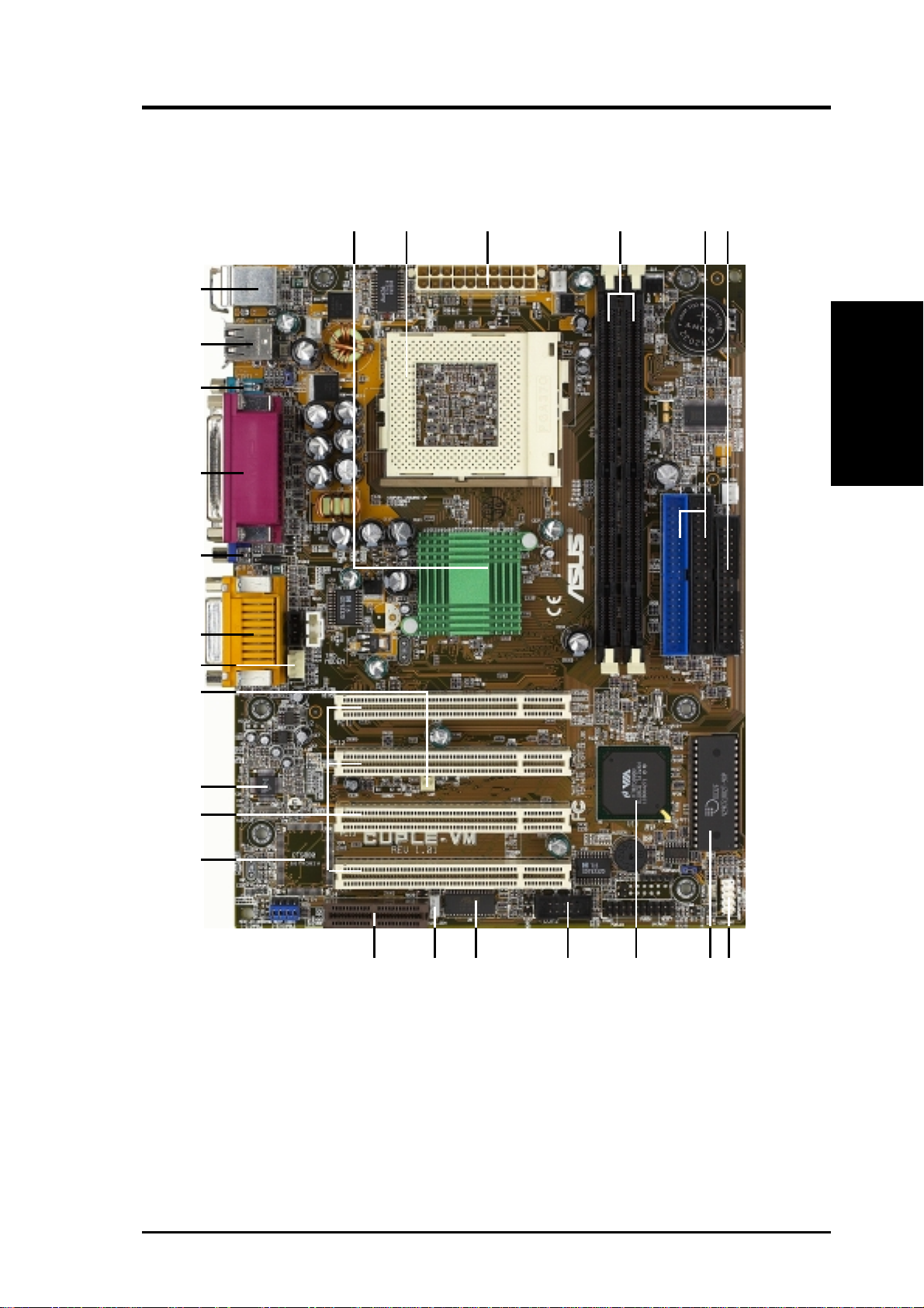
2.2 Motherboard Components
See opposite page for locations.
Processor Support Socket 370 for Intel
Motherboard Parts
2. FEATURES
Expansion Slots 4 PCI Slots .............................................................................. 15
Location
®
Processors .............................................. 2
(NOTE: CPU thermal sensor is integrated on the motherboard,
located near the center of the CPU heat source, just below the
CPU socket)
Chipsets VIA
Main Memory Maximum 1GB support
System I/O 1 Floppy Disk Driver Connector .............................................. 6
®
VT8601A (PLE133) system controller............................ 1
®
VT82C686B PCIset.......................................................... 9
VIA
2Mbit Programmable Flash EEPROM ..................................... 8
2 DIMM Sockets ...................................................................... 4
VC133/PC133 memory support
1 Audio Modem Riser ............................................................ 13
2 IDE Connectors (UltraDMA/100 Support) ........................... 5
1 Modem Connector ............................................................... 18
1 Parallel Port Connector ............................................. (Top) 21
1 VGA Connector ................................................... (Bottom) 20
1 Serial COM1 Port Connector .............................. (Bottom) 22
1 Serial COM2 Port Header .................................................. 10
USB Connectors (Port 0 & Port 1) ........................ (Bottom) 23
USB Connectors (Port 2 & Port 3) ........................................... 7
1 PS/2 Mouse Connector .............................................. (Top) 24
1 PS/2 Keyboard Connector ................................... (Bottom) 24
Audio AC’97 V2.1 Audio Codec ..................................... (optional) 16
Creative Audio Controller ..................................... (optional) 14
1 Game/MIDI Connector (on audio model only)...........(Top) 19
1 Line Out Connector (on audio model only) ........ (Bottom) 19
1 Line In Connector (on audio model only) ........... (Bottom) 19
1 Microphone Connector (on audio model only) ... (Bottom) 19
Network Features Wake-On-LAN Connector...................................................... 12
Wake-On-Ring Connector ...................................................... 17
Hardware Monitoring System Voltage Monitoring (integrated in ASUS ASIC) ....... 11
3 Fan Power and Speed Monitoring Connectors
Power ATX Power Supply Connector ................................................. 3
Form Factor Micro A TX
12
ASUS CUPLE-VM User’s Manual
Page 13
2. FEATURES
2.2.1 Component Locations
24
23
22
21
20
19
18
1
24
3
5
6
2. FEATURES
Motherboard Parts
17
16
15
-
14
8
91113 12 10
7
ASUS CUPLE-VM User’s Manual 13
Page 14
3. HARDWARE SETUP
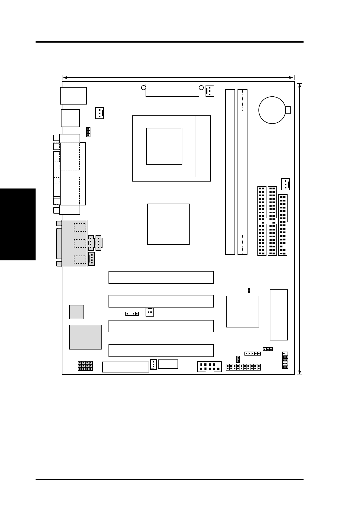
3.1 Motherboard Layout
19.2cm (7.56in)
PS/2
T: Mouse
B: Keyboard
Bottom:
USB1
USB2
COM1
Motherboard Layout
3. H/W SETUP
VGA
GAME_AUDIO
Line
Out
Line
In
Mic
In
CPU_FAN
USBPWR1
PARALLEL PORT
CD
AUX
MODEM
ATX Power Connector
Socket 370
VIA
VT8601A
Chipset
PWR_FAN
CR2032 3V
Lithium Cell
CMOS Power
CHA_FAN
Secondary IDE
Primary IDE
DIMM Socket 1 (64/72-bit, 168-pin module)
DIMM Socket 2 (64/72-bit, 168-pin module)
24.4cm (9.6in)
0
2
1
3
FLOPPY
PCI 1
R139
Audio
Codec
CHASS
PCI 2
WOR
VIA
VT82C686B
Chipset
PCI 3
CREATIVE
CT5880
AC97_EN
CUPLE-VM
Audio Modem Riser
(AMR)
PCI 4
ASUS
ASIC
WOLCON
IDELED
COM2
Grayed components are optional at the time of purchase.
IR
Flash EEPROM
(Programable BIOS)
USBPWR2
USBPORT
PANEL
14
ASUS CUPLE-VM User’s Manual
Page 15

3. HARDWARE SETUP
3.2 Layout Contents
Motherboard Settings
1) USBPWR1/USBPWR2 p. 17 USB Device W ake-up (Disable/Enable)
2) AC97_EN p. 17 Audio CODEC Setting (Disable/Enable)
Expansion Slots/Sockets
1) System Memory p.18 System Memory Support
2) DIMM1/2 p.19 DIMM Memory Module Support
3) Socket 370 p.20 CPU Support
4) PCI1/2/3/4 p.22 32-bit PCI Bus Expansion Slots
5) AMR p.24 Advanced Modem Riser Slot
Connectors
1) PS2KBMS p.25 PS/2 Mouse Port Connector (6 pin female)
2) PS2KBMS p.25 PS/2 Keyboard Port Connector (6 pin female)
3) USB p.26 Universal Serial Bus Connectors 0 & 1 (Two 4 pin female)
4) COM1/2 p.26 Serial Port Connector (9 pin male)
5) VGA p.26 Monitor Output Connector (15 pin male)
6) PRINTER p.27 Parallel Port Connector (25 pin female)
7) GAME_AUDIO p.27 Game/MIDI Connector (15 pin female) (optional)
8) GAME_AUDIO p.27 Audio Port Connectors (Three 1/8” female) (optional)
9) PRIMAR Y ID E p.28 IDE Connectors (T wo 40-1 pin)
SECONDARY IDE
10) FLOPPY p.29 Floppy Disk Drive Port Connector (34 pin)
11) IR p.29 Infrared Module Connector (5 pin)
12) WOL_CON p.30 Wake-On-LAN Connector (3 pin)
13) WOR p.30 Wake-On-Ring Connector (2 pin)
14) CPU_, PS_, CHASS_FAN p.31 Chassis, Power Supply, CPU Fan Connectors (3 pin)
15) CD_IN, AUX, MODEM p.32 Internal Audio Connectors (Three 4 pin)
16) USB2 p.32 USB Header (10-1 pin)
17) ATXPWR p.33 ATX Power Supply Connector (20 pin)
18) IDELED p.33 IDE Activity LED (2 pin)
19) SPEAKER (PANEL) p.34 System Warning Speaker Connector (4 pin)
20) PWR.LED (PANEL) p.34 System Power LED Lead (3 pin)
21) RESET (PANEL) p.34 Reset Switch Lead (2 pin)
22) PWR.SW (PANEL) p.34 ATX / Soft-Off Switch Lead (2 pin)
ASUS CUPLE-VM User’s Manual 15
Page 16

3. HARDWARE SETUP
3.3 Hardware Setup Procedure
Before using your computer, you must complete the following steps:
1. Check Motherboard Settings
2. Install Memory Modules
3. Install the Central Processing Unit (CPU)
4. Install Expansion Cards
5. Connect Ribbon Cables, Panel Wires, and Power Supply
6. Setup the BIOS Software
3.4 Motherboard Settings
This section explains in detail how to change your motherboard’s function settings
through the use of switches and/or jumpers.
W ARNING! Computer motherboards and expansion cards contain very delicate
Integrated Circuit (IC) chips. T o protect them against damage from static electricity ,
you should follow some precautions whenever you work on your computer .
1. Unplug your computer when working on the inside.
2. Use a grounded wrist strap before handling computer components. If you do
not have one, touch both of your hands to a safely grounded object or to a
metal object, such as the power supply case.
3. Hold components by the edges and try not to touch the IC chips, leads or
connectors, or other components.
4. Place components on a grounded antistatic pad or on the bag that came with
the component whenever the components are separated from the system.
5. Ensure that the ATX power supply is switched off before you plug in or
remove the ATX power connector on the motherboard.
WARNING! Make sure that you unplug your power supply when adding or
removing system components. Failure to do so may cause severe damage to your
motherboard, peripherals, and/or components. The onboard LED when lit acts as
a reminder that the system is in suspend or soft-off mode and not powered OFF.
16 ASUS CUPLE-VM User’s Manual
Page 17
3. HARDWARE SETUP
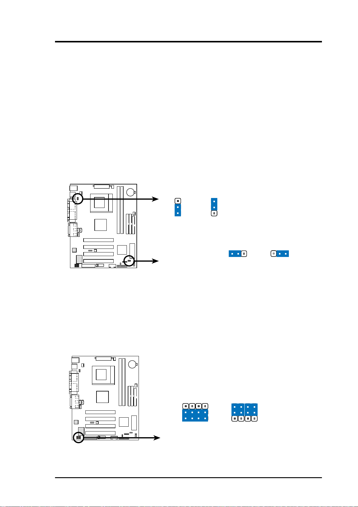
1) USB Device Wake-up (USBPWR1 / USBPWR2)
Set these jumpers to +5V to allow wake up from the S1 sleep state (CPU stopped;
RAM refreshed; system running in low power mode) using the connected USB
devices. Set to +5VSB to allow wake up from S3 sleep state (no power to CPU;
RAM in slow refresh; power supply in reduced power mode). The default setting
for the three jumpers is 1-2 to select +5V (because not all computers have the
appropriate power supply).
NOTES:
1. This feature requires an ATX power supply that can supply at least 2A on
the +5VSB lead when these jumpers are set to +5VSB. Otherwise, the
system does not power up.
2. The total current consumed must NOT exceed the power supply capability
(+5VSB) whether under normal working conditions or in sleep mode.
USBPWR1
3
22
1
Disable
(Default)
CUPLE-VM
CUPLE-VM USB Device Wake Up
Enable
USBPWR2
12
Disable
(Default)
23
Enable
2) Audio CODEC Setting (12 pin AC97_EN)
Four jumpers control the onboard Audio CODEC setting. If the optional
Creative audio chip is on board, these jumpers are not functional. However,
without the Creative audio chip, the jumpers may be reset to disable the
standard onboard audio CODEC. If disabled, an independent PCI sound card
may be installed onboard. The default setting, [1-2], enables the CODEC function.
To disable the CODEC, cover all jumpers, [2-3].
SPK
ADN#
AUD_EN1
AUD_EN2
3
2
1
CUPLE-VM
(Default)
SPK
ADN#
AUD_EN1
AUD_EN2
3
2
1
DisableEnable
CUPLE-VM Audio Codec Setting
ASUS CUPLE-VM User’s Manual 17
Page 18

3. HARDWARE SETUP
3.5 System Memory (DIMM)
This motherboard uses only Dual Inline Memory Modules (DIMMs). Two sockets
are available for 3.3Volt (power level) unbuffered Synchronous Dynamic Random
Access Memory (SDRAM) of 8, 16, 32, 64, 128, 256, or 512MB to form a memory
size between 8MB to 1GB. One side (with memory chips) of the DIMM takes up one
row on the motherboard. This motherboard also supports NEC’s Virtual Channel
(VC) SDRAMs.
Memory speed setup is recommended through SDRAM Configuration under “Chipset
Features Setup”.
IMPORTANT (see General DIMM Notes below for more):
• SDRAMs used must be compatible with the current Intel PC133
SDRAM specification.
• DO NOT attempt to mix PC133 SDRAMs with VCM SDRAMs.
• The motherboard only supports PC100 / PC133 DIMMs or VC
SDRAMs for system memory. Registered DIMMs are not supported.
Install memory in any combination as follows:
DIMM Location 168-pin DIMM Total Memory
Socket 1 (Rows 0&1) SDRAM 8, 16, 32, 64, 128, 256, 512MB x1
Socket 2 (Rows 2&3) SDRAM 8, 16, 32, 64, 128, 256, 512MB x1
Total System Memory (Max 1024MB) =
3.5.1 General DIMM Notes
• DIMMs that have more than 18 chips are not supported on this motherboard.
• For the system CPU bus to operate at 100MHz/133MHz, use only PC100-/PC133-
compliant DIMMs.
• ASUS motherboards support SPD (Serial Presence Detect) DIMMs. This is the
memory of choice for best performance vs. stability.
• BIOS shows SDRAM memory on bootup screen.
• Single-sided DIMMs come in 16, 32, 64,128, 256MB; double-sided come in 32, 64,
128, 256, 512MB.
WARNING! Be sure that the DIMM you use can handle the specified SDRAM
MHz or else bootup will not be possible.
18 ASUS CUPLE-VM User’s Manual
Page 19
3. HARDWARE SETUP
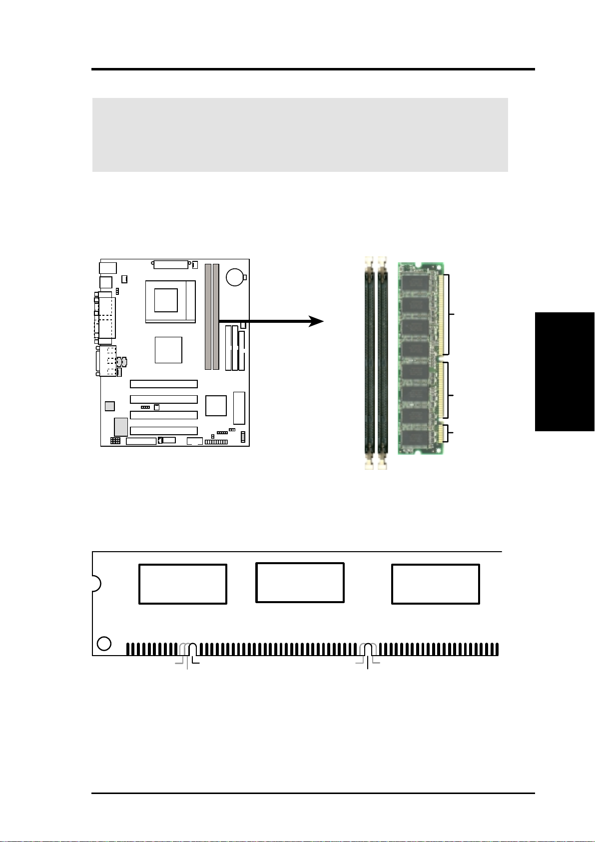
3.5.2 Memory Installation
WARNING! Make sure that you unplug your power supply when adding or
removing memory modules or other system components. Failure to do so may
cause severe damage to both your motherboard and expansion cards (see 3.3
Hardware Setup Procedure for more information).
Insert the module(s) as shown. Because the number of pins are different on either
side of the breaks, the module will only fit in the orientation shown. DRAM SIMM
modules have the same pin contacts on both sides. SDRAM DIMMs have different
pin contacts on each side and therefore have a higher pin density.
88 Pins
60 Pins
CUPLE-VM
20 Pins
CUPLE-VM 168-Pin DIMM Sockets
The DIMMs must be 3.3Volt unbuffered SDRAMs. To determine the DIMM type,
check the notches on the DIMMs (see figure below)
168-Pin DIMM Notch Key Definitions (3.3V)
DRAM Key Position
RFU
Buffered
Unbuffered
The notches on the DIMM will shift between left, center, or right to identify the type
and also to prevent the wrong type from being inserted into the DIMM slot on the
motherboard. You must tell your retailer the correct DIMM type before purchasing.
This motherboard supports four clock signals per DIMM.
Voltage Key Position
5.0V
Reserved
3.3V
3. H/W SETUP
System Memory
ASUS CUPLE-VM User’s Manual 19
Page 20
3. HARDWARE SETUP
3.6 Central Processing Unit (CPU)
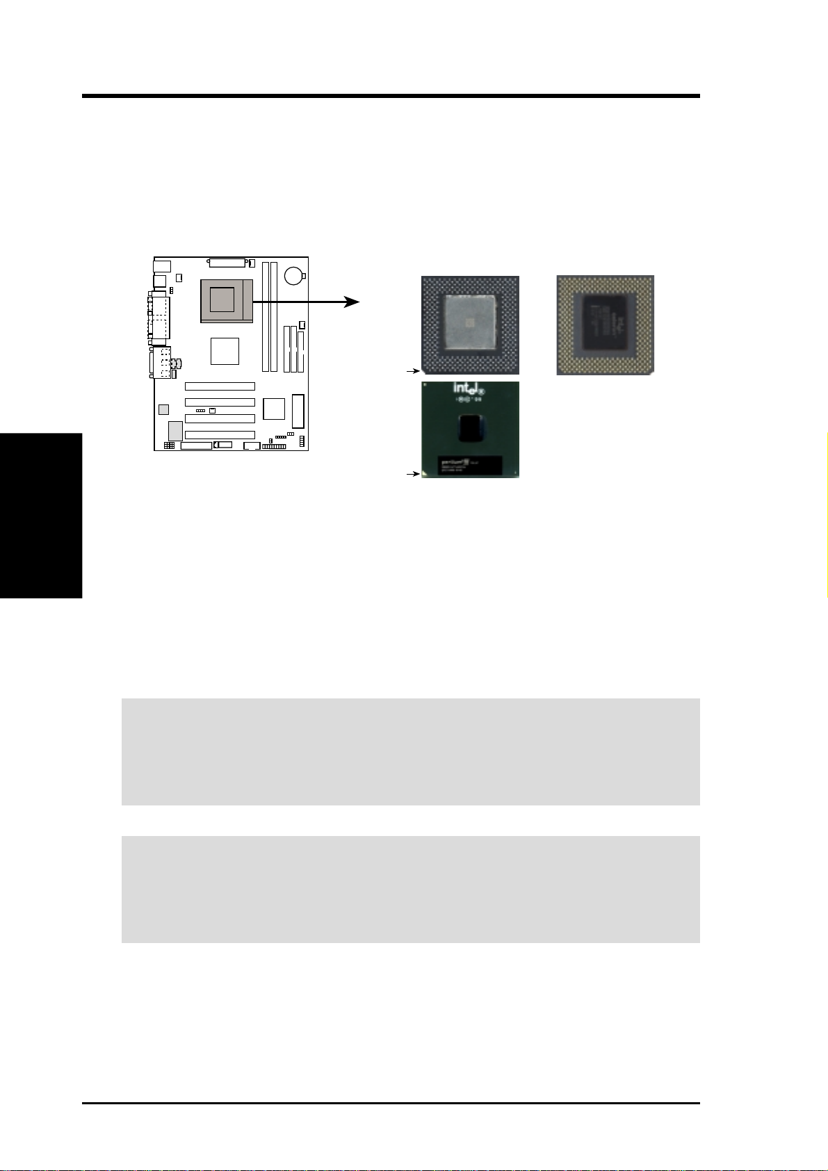
The motherboard comes with a ZIF Socket for the supported CPUs listed in section
2.1.1 Specifications. The following illustration shows the CPU socket location on
the motherboard and the correct CPU orientation.
Socket 370 CPU (Top) Socket 370 CPU (Bottom)
Celeron
Notch
System Memory
3. H/W SETUP
Note in the illustration that CPUs have marks (usually a notch or a gold mark on one
corner) to help identify the proper orientation and enable correct installation of a
CPU. It is important that you match the marked corner of the CPU with the
corresponding corner on the socket so as not to damage the CPU pins.
The CPU picture above is for reference only. Usually, when you buy a CPU, the
heatsink and fan are already attached to the CPU. If a heatsink and fan did not come
with the package, make sure you obtain one before installing the CPU.
WARNING! Be sure that there is sufficient air circulation across the processor’s
heatsink by regularly checking that your CPU fan is working. W ithout sufficient
circulation, the processor could overheat and damage both the processor and the
motherboard. You may install an auxiliary fan, if necessary.
CUPLE-VM
CUPLE-VM Socket 370
Pentium III
Gold Arrow
CAUTION! Be careful not to scrape the motherboard when mounting a clamp-
style processor fan or else damage may occur to the motherboard. When mounting
a heatsink onto your CPU, make sure that the CPU capacitors do not touch the
heatsink; otherwise, your CPU will be damaged!
20 ASUS CUPLE-VM User’s Manual
Page 21
3. HARDWARE SETUP
3.6.1 CPU Installation
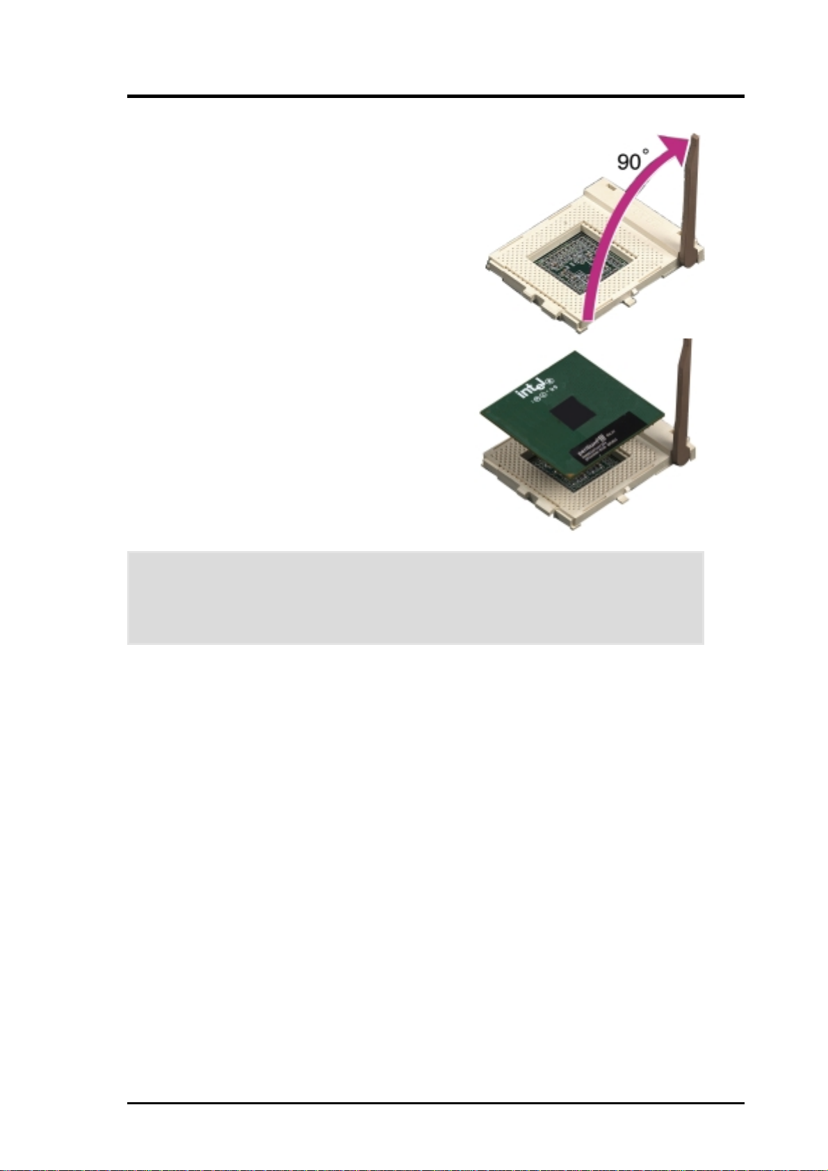
Follow these steps to install a CPU.
1. Locate the ZIF socket on the motherboard.
2. Unlock the socket by pressing the lever
sideways then lifting it up to a 90°-100°
angle.
3. Position the CPU above the socket such
that its notched or marked corner matches
the socket corner near the end of the lever,
while making sure that the CPU is parallel
to the socket.
4. Carefuly insert the CPU into the socket
until it fits in place.
CAUTION! The CPU fits only in one orientation. Do not force the CPU into the
socket to prevent bending the pins and damaging the CPU. If the CPU does not
fit completely, check its orientation or check for bent pins.
5. When the CPU is in place, press it firmly on the socket while you push down the
socket lever to secure the CPU. The lever clicks on the socket indicating that it
is locked.
6. Attach the heatsink and fan to the CPU, if they were not pre-installed by the
vendor . Refer to the installation instructions that came with the heatsink and fan.
NOTE: Do not forget to set the correct Bus Frequency and Multiple
(frequency multiple setting is available only on unlocked processors) for the
processor to avoid start-up problems.
ASUS CUPLE-VM User’s Manual 21
Page 22
3. HARDWARE SETUP
3.7 Expansion Cards
In the future, you may need to install expansion cards. The motherboard has five
PCI expansion slots to support these cards. Follow the steps in the next section
when installing expansion cards.
W ARNING! Unplug the system power cord when adding or removing expansion
cards or other system components. Failure to do so may cause severe damage to
both the motherboard and expansion cards.
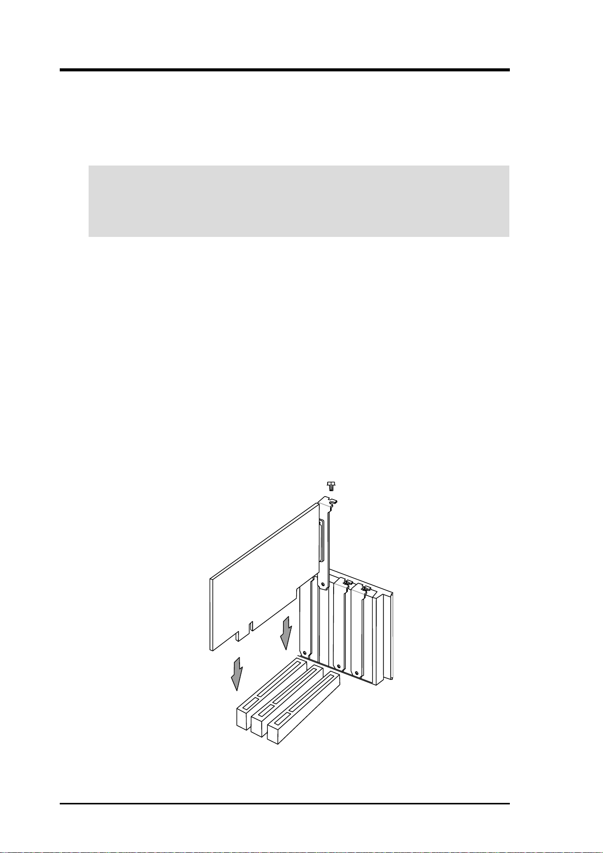
3.7.1 Installing an Expansion Card
1. Read the documentation that comes with the expansion card and make any
necessary hardware settings for the card before installing it.
2. Remove the system unit cover and the bracket plate on the slot you intend to use.
Keep the screw for later use.
3. Align the card connectors with the slot and press firmly until the card fits in
place.
4. Secure the card to the slot with the screw you removed earlier.
5. Replace the system cover.
6. Change the necessary BIOS settings, if any.
(see section 4.4.3 PCI Configuration to change the settings.)
7. Install the necessary software drivers for the expansion card.
22 ASUS CUPLE-VM User’s Manual
Page 23

3. HARDWARE SETUP
3.7.2 Assigning IRQs for Expansion Cards
Some expansion cards need an IRQ to operate. Generally , an IRQ must be exclusively
assigned to one use. In a standard design, there are 16 IRQs available but most of
them are already in use, leaving 6 IRQs free for expansion cards. If your motherboard
has PCI audio onboard, an additional IRQ will be used. If your motherboard also
has MIDI enabled, another IRQ will be used, leaving 4 IRQs free.
IMPORTANT : If using PCI cards on shared slots, make sure that the drivers support
“Share IRQ” or that the cards do not need IRQ assignments. Conflicts arise between
the two PCI groups that will make the system unstable or cards inoperable.
The following table lists the default IRQ assignments for standard PC devices. Use
this table when configuring your system and for resolving IRQ conflicts.
Standard Interrupt Assignments
IRQ Priority Standard Function
0 1 System Timer
1 2 Keyboard Controller
2 N/A Programmable Interrupt
3* 11 Communications Port (COM2)
4* 12 Communications Port (COM1)
5* 13 Sound Card (sometimes LPT2)
6 14 Floppy Disk Controller
7* 15 Printer Port (LPT1)
8 3 System CMOS/Real Time Clock
9* 4 ACPI Mode when used
10* 5 IRQ Holder for PCI Steering
11* 6 IRQ Holder for PCI Steering
12* 7 PS/2 Compatible Mouse Port
13 8 Numeric Data Processor
14* 9 Primary IDE Channel
15* 10 Secondary IDE Channel
*These IRQs are usually available for ISA or PCI devices.
Interrupt Request Table for this Motherboard
INT-A INT-B INT-C INT-D
PCI slot 1 — shared ——
PCI slot 2 ——shared —
PCI slot 3 ———shared
PCI slot 4 shared ———
AMR slot (AC97) ———shared
Onboard audio controller ———shared
Onboard USB controller shared ———
ASUS CUPLE-VM User’s Manual 23
Page 24
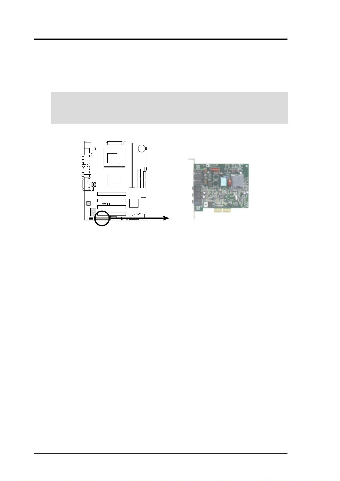
3. HARDWARE SETUP
3.7.4 Advanced Modem Riser (AMR) Slot
This motherboard supports a specially designed audio/modem card called an AMR.
Main processing is done through software and controlled by the motherboard’s system
chipset. This provides an upgradeable audio and /or modem solution at an incredibly
affordable cost.
IMPORTANT: The slot can only accept a specially designed AMR card (optional).
Do not attempt to connect other types of expansion cards to the AMR slot. For
availability, see your vendor or dealer.
CUPLE-VM
CUPLE-VM Audio Modem Riser
(AMR) Connector
24 ASUS CUPLE-VM User’s Manual
Page 25
3. HARDWARE SETUP
3.8 External Connectors
WARNING! Some pins are used for connectors or power sources. These are
clearly distinguished from jumpers in the Motherboard Layout. Placing jumper
caps over these connector pins will cause damage to your motherboard.
IMPORTANT: Ribbon cables should always be connected with the red stripe to
Pin 1 on the connectors. Pin 1 is usually on the side closest to the power connector on hard drives and CD-ROM drives, but may be on the opposite side on
floppy disk drives. Check the connectors before installation because there may
be exceptions. IDE ribbon cable must be less than 46 cm (18 in.), with the second drive connector no more than 15 cm (6 in.) from the first connector.
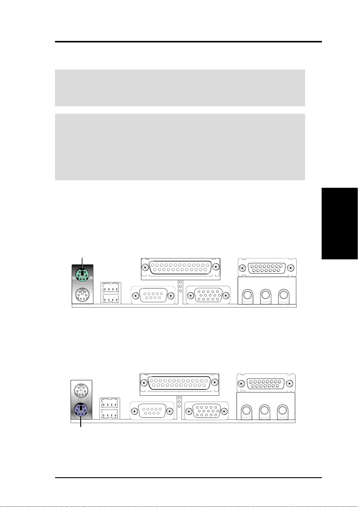
1) PS/2 Mouse Connector (Green 6-pin PS2KBMS)
The system will direct IRQ12 to the PS/2 mouse if one is detected. If one is not
detected, expansion cards can use IRQ12. See PS/2 Mouse Function Control
in 4.4 Advanced Menu.
PS/2 Mouse (6-pin female)
Connectors
3. H/W SETUP
2) PS/2 Keyboard Connector (Purple 6-pin PS2KBMS)
This connection is for a standard keyboard using an PS/2 plug (mini DIN). This
connector will not allow standard AT size (large DIN) keyboard plugs. You
may use a DIN to mini DIN adapter on standard AT keyboards.
PS/2 Keyboard (6-pin female)
ASUS CUPLE-VM User’s Manual 25
Page 26
3. H/W SETUP
Connectors
3. HARDWARE SETUP
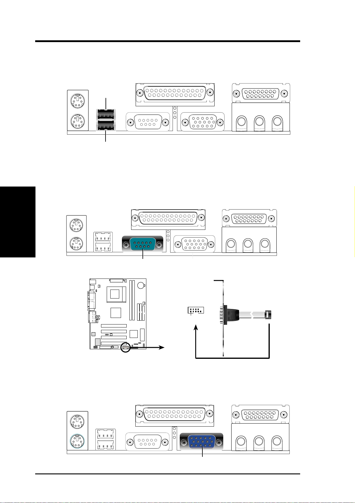
3) Universal Serial BUS Ports 0 & 1 (Black two 4-pin USB)
T wo USB ports are available for connecting USB devices. If these are not enough,
a USB header is available for two additional USB port connectors. See USB
Headers later in this section.
USB 1
Universal Serial Bus (USB) 2
4) Serial Port Connectors (Teal/Turquoise 9-pin COM1/COM2)
One serial port can be used for pointing devices or other serial devices. An additional serial p[ort is available using a serial port bracket. To set up these ports,
see Onboard Serial Port 1 in 4.4.2 I/O Device Configuration for settings.
COM 1
Serial Port (9-pin male)
COM2
PIN 1
CUPLE-VM
CUPLE-VM Serial COM2 Connector
5) Monitor Output Connector (Blue 15-pin VGA)
This connector is for output to a VGA-compatible device.
VGA Monitor (15-pin female)
26 ASUS CUPLE-VM User’s Manual
Page 27
3. HARDWARE SETUP
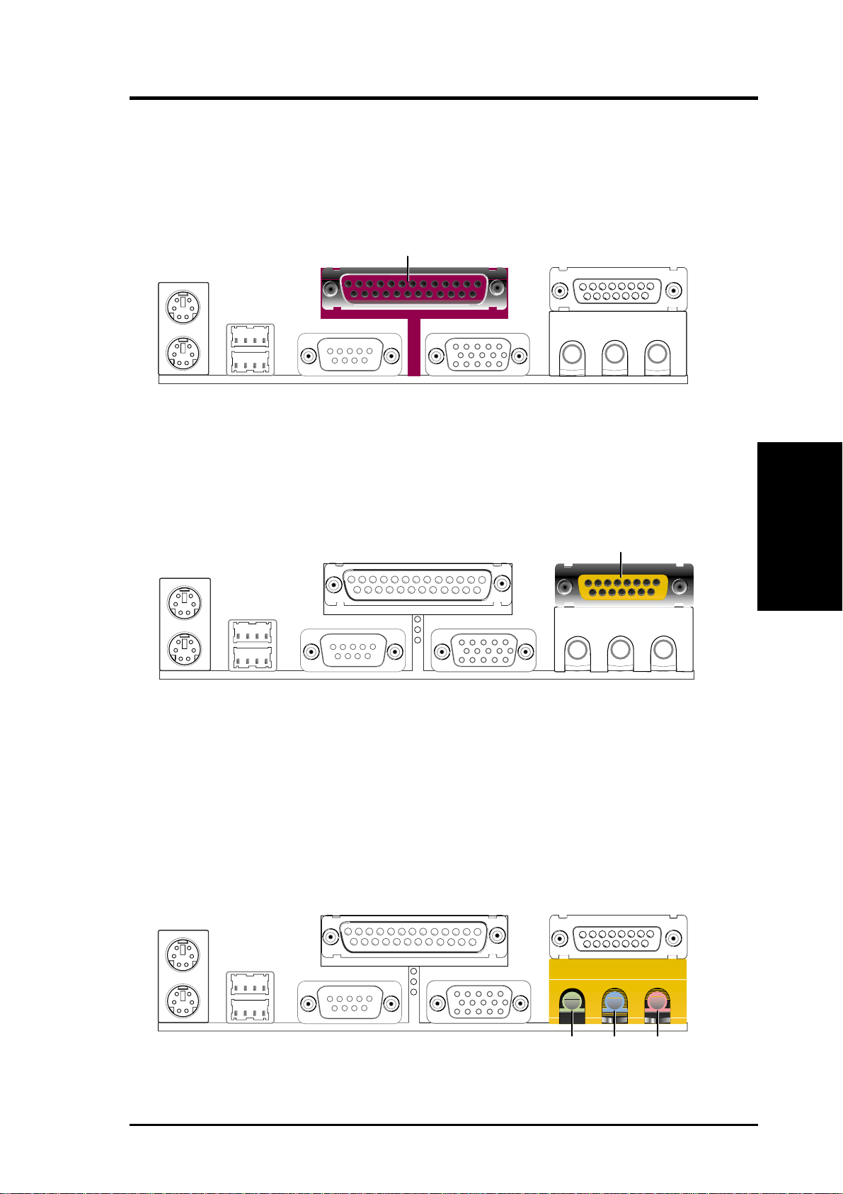
6) Parallel Port Connector (Burgundy 25-pin PRINTER)
You can enable the parallel port and choose the IRQ through Onboard Parallel
Port (see 4.4.2 I/O Device Configuration).
NOTE: Serial printers must be connected to the serial port.
Parallel (Printer) Port (25-pin female)
7) Game/MIDI Connector (Gold 15-pin GAME_AUDIO) (optional)
You may connect game joysticks or game pads to this connector for playing
games. Connect MIDI devices for playing or editing professional audio.
Joystick/MIDI (15-pin female)
8) Audio Port Connectors (Three 1/8” GAME_AUDIO) (optional)
Line Out (lime) can be connected to headphones or preferably powered speak-
ers. Line In (light blue) allows tape players or other audio sources to be re-
corded by your computer or played through the Line Out (lime). Mic (pink)
allows microphones to be connected for inputting voice.
Connectors
3. H/W SETUP
MicLine InLine Out
1/8" Stereo Audio Connectors
ASUS CUPLE-VM User’s Manual 27
Page 28
3. H/W SETUP
Connectors
3. HARDWARE SETUP
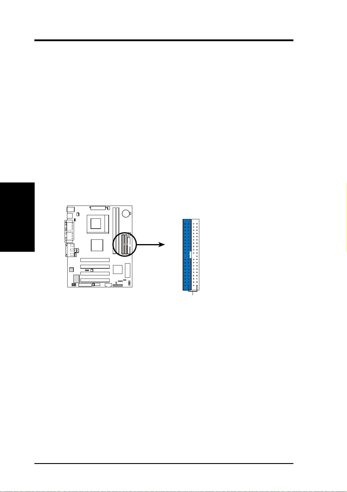
9) Primary (Blue) / Secondary IDE Connectors (40-1 pin IDE1/IDE2)
These connectors support the provided UltraDMA/66 IDE hard disk ribbon cable.
Connect the cable’s blue connector to the motherboard’s primary (recommended)
or secondary IDE connector, and then connect the gray connector to your
UltraDMA/66 slave device (hard disk drive) and the black connector to your
UltraDMA/66 master device. It is recommended that non-UltraDMA/66 devices
be connected to the secondary IDE connector . If you install two hard disks, you
must configure the second drive to Slave mode by setting its jumper accordingly . Refer to your hard disk documentation for the jumper settings. BIOS now
supports specific device bootup (see 4.6 Boot Menu). (Pin 20 is removed to
prevent inserting in the wrong orientation when using ribbon cables with
pin 20 plugged). If you have more than two UltraDMA/66 devices, you will
need to purchase another UltraDMA/66 cable.
NOTE: The hole near the blue connector on the UltraDMA/66 cable is intentional.
TIP: You may configure two hard disks to be both Masters with two ribbon
cables – one for the primary IDE connector and another for the secondary IDE
connector . You may install one operating system on an IDE drive and another on
a SCSI drive and select the boot disk through 4.6 Boot Menu.
CUPLE-VM
CUPLE-VM IDE Connectors
NOTE: Orient the red markings
(usually zigzag) on the IDE
ribbon cable to PIN 1.
Primary IDE Connector
PIN 1
Secondary IDE Connector
28 ASUS CUPLE-VM User’s Manual
Page 29
3. HARDWARE SETUP
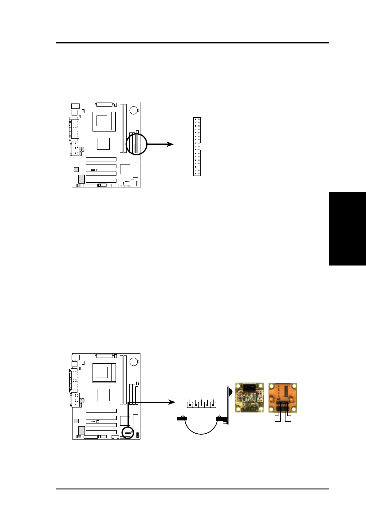
10) Floppy Disk Drive Connector (34-1 pin FLOPPY)
This connector supports the provided floppy drive ribbon cable. After
connecting the single end to the board, connect the two plugs on the other end to
the floppy drives. (Pin 5 is removed to prevent inserting in the wrong orien-
tation when using ribbon cables with pin 5 plugged).
NOTE: Orient the red markings on
the floppy ribbon cable to
PIN 1
CUPLE-VM
PIN 1
CUPLE-VM Floppy Disk Drive Connector
11) Standard Infrared Module Connector (5-pin IR)
This connector supports an optional wireless transmitting and receiving infrared
module. This module mounts to a small opening on system cases that support
this feature. You must also configure the setting through UART2 Use Infrar ed
(see 4.4.2 I/O Device Configuration) to select whether UART2 is directed for
use with COM2 or IrDA. Use the five pins as shown in Back View and connect
a ribbon cable from the module to the motherboard’s SIR connector according
to the pin definitions.
Connectors
3. H/W SETUP
+5V
1
CUPLE-VM
CUPLE-VM Infrared Module Connector
ASUS CUPLE-VM User’s Manual 29
IR
(NC)
IRRX
GND
IRTX
Front View Back View
IRTX
GND
IRRX
+5V
(NC)
Page 30
3. HARDWARE SETUP
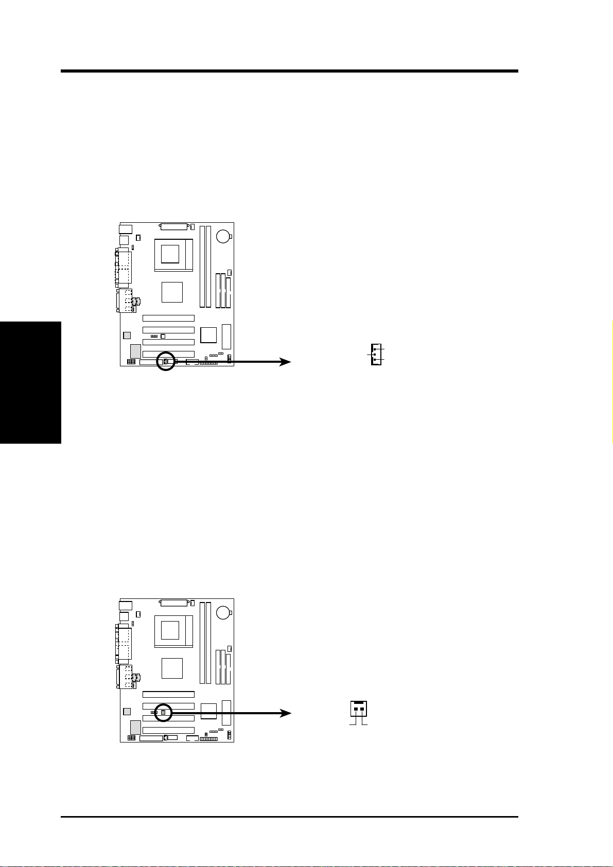
12) Wake-On-LAN Connector (3-pin WOL_CON)
This connector connects to a LAN card with a Wake-On-LAN output, such as
the ASUS PCI-L101 Ethernet card (see 7. Appendix). The connector powers up
the system when a wakeup packet or signal is received through the LAN card.
IMPORTANT: This feature requires that Wake-On-LAN features are enabled
(see 4.4.3 Power Management) and that your system has an A TX power supply
with at least 720mA +5V standby power.
IMPORTANT: Requires an ATX power
supply with at least 720mA +5 volt
standby power.
WOL_CON
3. H/W SETUP
Connectors
CUPLE-VM
Ground
CUPLE-VM Wake-On-LAN Connector
+5 Volt Standby
PME
13) Wake-On-Ring Connector (2-pin WOR)
This connector connects to internal modem cards with a Wake-On-Ring output.
The connector powers up the system when a ringup packet or signal is received
through the internal modem card. NOTE: For external modems, W ake-On-Ring
is detected through the COM port.
IMPORTANT: This feature requires that Wake-On-Ring is enabled (see 4.4.3
Power Management) and that your system has an ATX power supply with at
least 720mA +5V standby power.
WOR
21
CUPLE-VM
CUPLE-VM Wake-On-Ring Connector
RI#Ground
30 ASUS CUPLE-VM User’s Manual
Page 31
3. HARDWARE SETUP
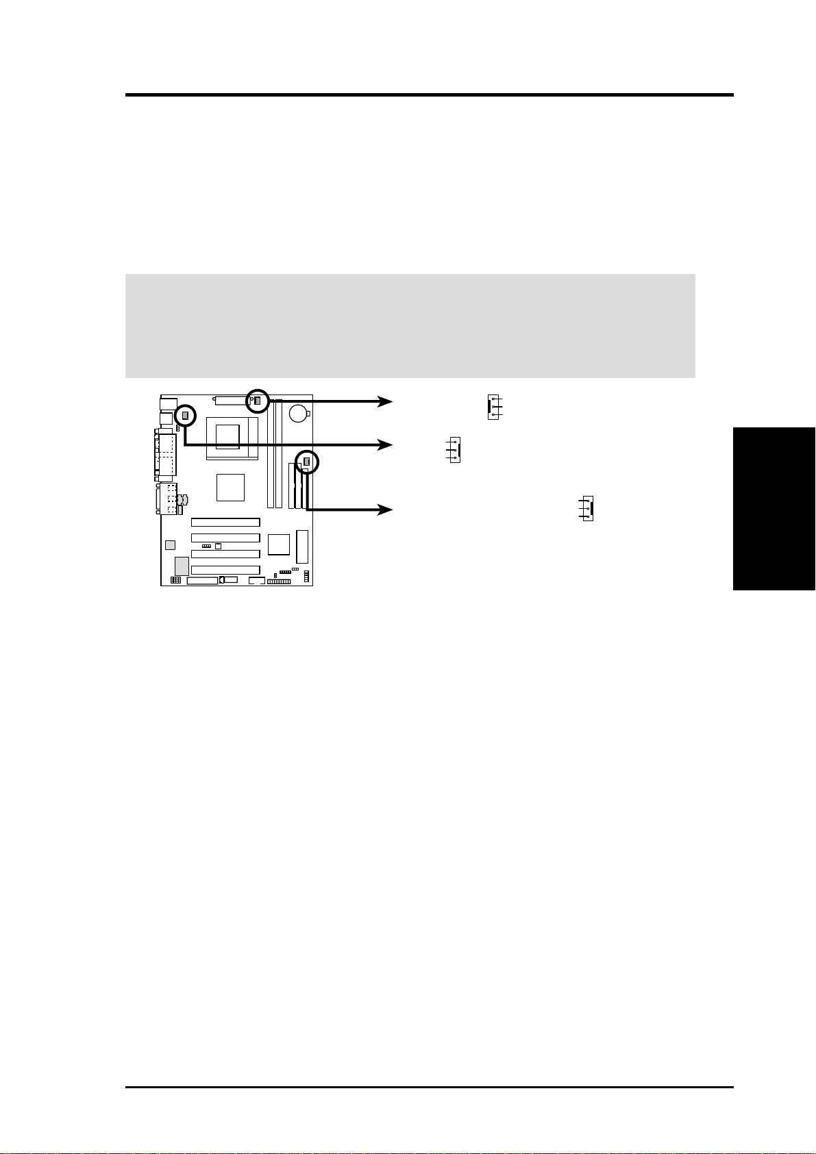
14) CPU, Power Supply, Chassis Fan Connectors (3-pin CPU_FAN, PS_FAN,
CHASS_FAN)
These connectors support cooling fans of 350mA (4.2 Watts) or less. Orient
the fans to blow air across the onboard heat sink. Depending on the fan
manufacturer, the wiring and plug may be different. The red wire should be
positive, while the black should be ground. NOTE: Rotations Per Minute (RPM)
can be monitored using ASUS PC Probe. (see 6. Software Reference).
WARNING! The CPU and/or motherboard will overheat if there is no airflow
across the CPU and onboard heatsinks. Damage may occur to the motherboard
and/or the CPU fan if these pins are incorrectly used. These are not jumpers,
do not place jumper caps over these pins.
Rotation
+12V
GND
CUPLE-VM
CUPLE-VM 12-Volt Cooling Fan Power
GND
+12V
Rotation
CPU_FAN
PWR_FAN
Rotation
+12V
GND
CHA_FAN
Connectors
3. H/W SETUP
ASUS CUPLE-VM User’s Manual 31
Page 32
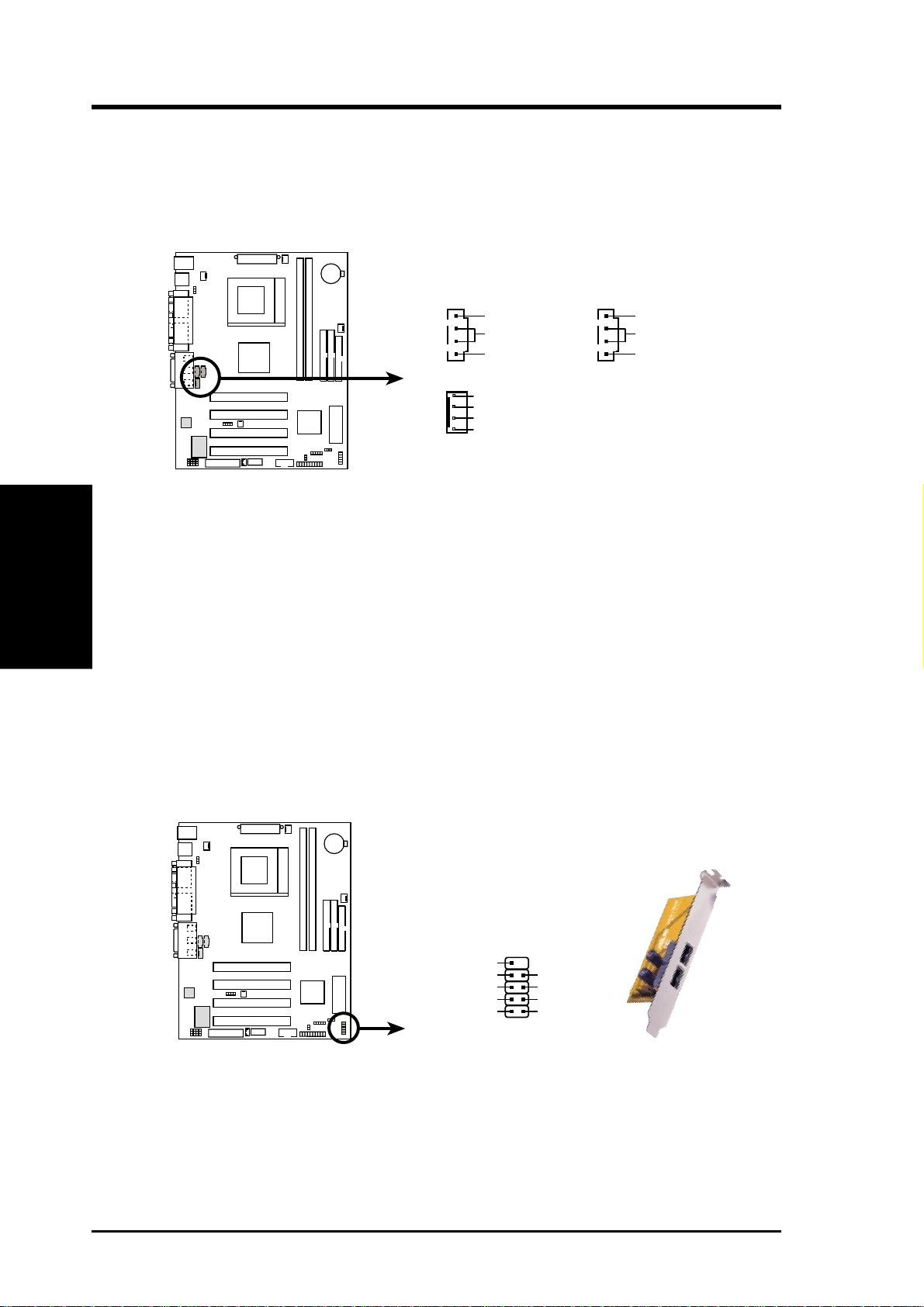
3. HARDWARE SETUP
15) Internal Audio Connectors (4-pin CD_IN, AUX, MODEM)
These connectors allow you to receive stereo audio input from such sound sources
as a CD-ROM, TV tuner, or MPEG card. The MODEM connector allows the
onboard audio to interface with a voice modem card with a similar connector.
AUX (White)CD (Black)
3. H/W SETUP
Connectors
CUPLE-VM
Right Audio Channel
Ground
Left Audio Channel
Modem-In
Ground
Ground
Modem-Out
MODEM
Right Audio Channel
Ground
Left Audio Channel
CUPLE-VM Internal Audio
Connectors
16) USB Header (10-1 pin USB2)
If the USB port connectors on the back panel are inadequate, this USB header is
available for two additional USB port connectors. Connect the USB headers to
the 2-port USB connector set and mount the bracket to an open slot on your
chassis.
USBPORT
10
5
NC
CUPLE-VM
GND
USBP2+
USBP2–
USB Power
1
GND
USBP3+
USBP3–
USB Power
6
CUPLE-VM USB Port
32 ASUS CUPLE-VM User’s Manual
Page 33
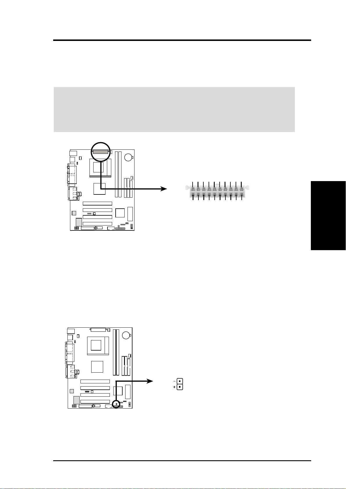
3. HARDWARE SETUP
17) ATX Power Supply Connector (20-pin block ATXPWR)
This connector connects to an ATX power supply. The plug from the power supply will only insert in one orientation because of the different hole sizes. Find the
proper orientation and push down firmly making sure that the pins are aligned.
IMPORTANT: Make sure that your ATX power supply can supply at least 10mA
on the +5-volt standby lead (+5VSB). You may experience difficulty in powering ON your system if your power supply cannot support the load. For WakeOn-LAN support, your ATX power supply must supply at least 720mA +5VSB.
+3.3 Volts
Ground
-12.0 Volts
Power Supply On
Ground
+3.3 Volts
+3.3 Volts
+5.0 Volts
CUPLE-VM
+5.0 Volts
+5.0 Volts
-5.0 Volts
+12.0 Volts
Power Good
+5V Standby
Ground
Ground
Ground
+5.0 Volts
Ground
Ground
CUPLE-VM ATX Power Connector
18) IDE Activity LED (2-pin IDELED)
This connector supplies power to the cabinet’s IDE activity LED. Read and
write activity by devices connected to the Primary/Secondary IDE and Primary/
Secondary ATA100 connectors will cause the LED to light up.
Connectors
3. H/W SETUP
CUPLE-VM
CUPLE-VM IDE Activity LED
ASUS CUPLE-VM User’s Manual 33
IDELED
TIP: If the case-mounted LED does not
light, try reversing the 2-pin plug.
Page 34
3. HARDWARE SETUP
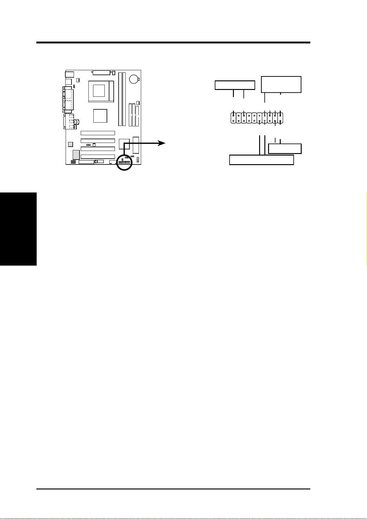
The following 20-pin PANEL illustration is for items 19-22:
3. H/W SETUP
Connectors
Speaker
Connector
Ground
Speaker
Ground
+5V
GND
PWR
Reset
Ground
Reset SW
CUPLE-VM
CUPLE-VM System Panel Connectors
Power LED
PLED-
PLED+
ATX Power Switch*
*
Requires an ATX power supply.
19) System Warning Speaker Connector (4-pin SPEAKER)
This 4-pin connector connects to the case-mounted speaker. Two sources
(LINE_OUT and SPEAKER) will allow you to hear system beeps and warnings. Only SPEAKER will allow you to hear system beeps before the integrated
audio has been properly initialized.
20) System Power LED Lead (3-1 pin PWRLED)
This 3-1 pin connector connects the system power LED, which lights when the
system is powered on and blinks when it is in sleep mode.
21) Reset Switch Lead (2-pin RESET)
This 2-pin connector connects to the case-mounted reset switch for rebooting
your computer without having to turn off your power switch. This is a preferred
method of rebooting to prolong the life of the system’s power supply.
22) ATX Power Switch Lead (2-pin PWRSW)
The system power is controlled by a momentary switch connected to this lead.
Pressing the button once will switch the system between ON and SOFT OFF.
Pushing the switch while in the ON mode for more than 4 seconds will turn the
system off. The system power LED shows the status of the system’s power.
34 ASUS CUPLE-VM User’s Manual
Page 35

3. HARDWARE SETUP
3.9 Starting Up the First Time
1. After all connections are made, close the system case cover.
2. Be sure that all switches are off (in some systems, marked with
3. Connect the power supply cord into the power supply located on the
back of your system case according to your system user’s manual.
4. Connect the power cord into a power outlet that is equipped with a surge
protector .
5. You may then turn on your devices in the following order:
a. Your monitor
b. External SCSI devices (starting with the last device on the chain)
c. Your system power. For ATX power supplies, you need to switch on
the power supply as well as press the ATX power switch on the front
of the case.
6. The power LED on the front panel of the system case will light. For
ATX power supplies, the system LED will light when the ATX power
switch is pressed. The LED on the monitor may light up or switch between orange and green after the system’s if it complies with “green”
standards or if it has a power standby feature. The system will then run
power-on tests. While the tests are running, the BIOS will alarm beeps
or additional messages will appear on the screen. If you do not see anything within 30 seconds from the time you turn on the power, the system
may have failed a power-on test. Recheck your jumper settings and connections or call your retailer for assistance.
).
Powering Up
3. H/W SETUP
Award BIOS Beep Codes
Beep Meaning
One short beep when No error during POST
displaying logo
Long beeps in an endless loop No DRAM installed or detected
One long beep followed by Video card not found or video card
three short beeps memory bad
High frequency beeps when CPU overheated
system is working System running at a lower frequency
ASUS CUPLE-VM User’s Manual 35
Page 36

7. During power-on, hold down <Delete> to enter BIOS setup. Follow the
* Powering Off your computer: You must first exit or shut down your
3. H/W SETUP
Powering Up
3. HARDWARE SETUP
instructions in 4. BIOS SETUP.
operating system before switching off the power switch. For ATX power
supplies, you can press the ATX power switch after exiting or shutting
down your operating system. If you use Windows 9X, click the Start
button, click Shut Down, and then click Shut down the computer?
The power supply should turn off after Windows shuts down.
NOTE: The message “Y ou can now safely turn of f your computer” will
not appear when shutting down with ATX power supplies.
ASUS CUPLE-VM User’s Manual36
Page 37
4. BIOS SETUP
4.1 Managing and Updating Your BIOS
4.1.1 Upon First Use of the Computer System
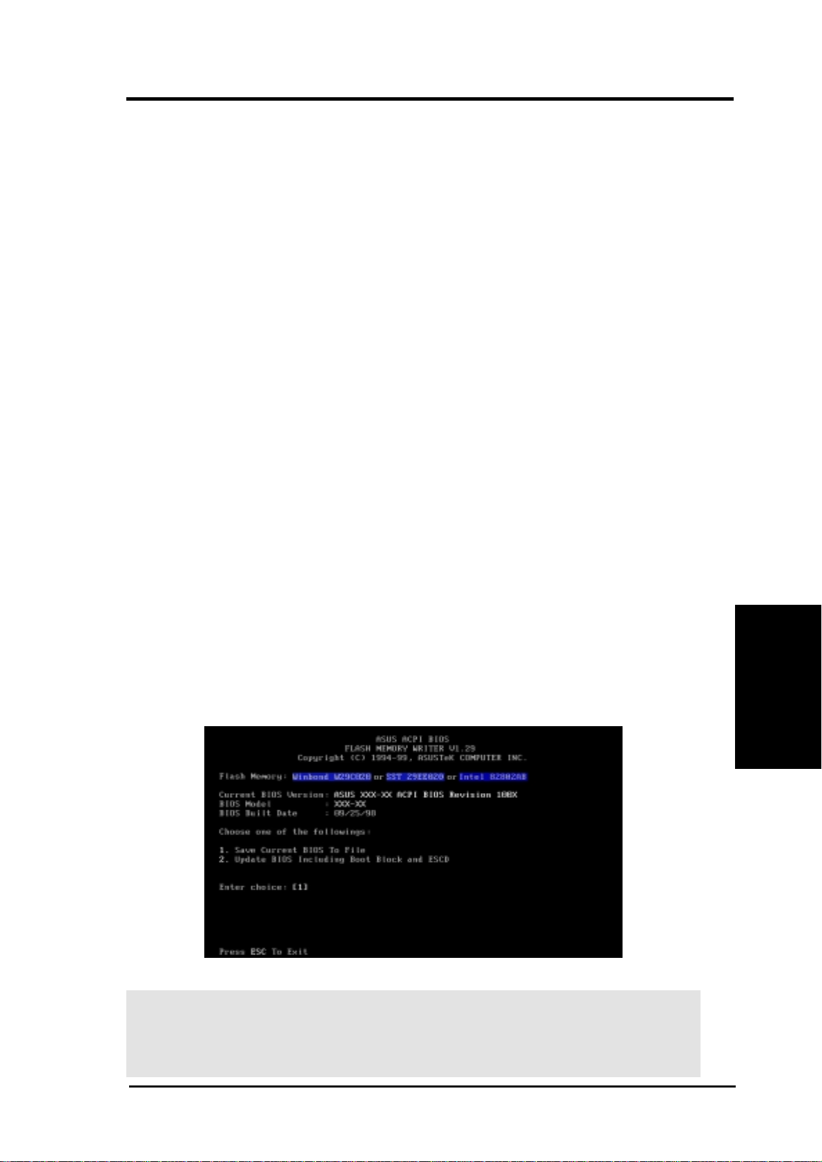
It is recommended that you save a copy of the original motherboard BIOS
along with a Flash Memory Writer utility (AFLASH.EXE) to a bootable
floppy disk in case you need to reinstall the BIOS later . AFLASH.EXE is a
Flash Memory Writer utility that updates the BIOS by uploading a new
BIOS file to the programmable flash ROM on the motherboard. This file
works only in DOS mode. To determine the BIOS version of your motherboard, check the last four numbers of the code displayed on the upper lefthand corner of your screen during bootup. Larger numbers represent a newer
BIOS file.
1. Type FORMAT A:/S at the DOS prompt to create a bootable system
floppy disk. DO NOT copy AUTOEXEC.BAT & CONFIG.SYS to the
disk.
2. T ype COPY D:\AFLASH\AFLASH.EXE A:\ (assuming D is your CD-
ROM drive) to copy AFLASH.EXE to the just created boot disk.
NOTE: AFLASH works only in DOS mode. It will not work with DOS
prompt in Windows and will not work with certain memory drivers that
may be loaded when you boot from your hard drive. It is recommended
that you reboot using a floppy.
3. Reboot your computer from the floppy disk. NOTE: BIOS setup must
specify “Floppy” as the first item in the boot sequence.
4. In DOS mode, type A:\AFLASH <Enter> to run AFLASH.
Updating BIOS
4. BIOS SETUP
IMPORTANT! If “unknown” is displayed after Flash Memory:, the memory
chip is either not programmable or is not supported by the ACPI BIOS and therefore, cannot be programmed by the Flash Memory Writer utility.
ASUS CUPLE-VM User’s Manual 37
Page 38
4. BIOS SETUP
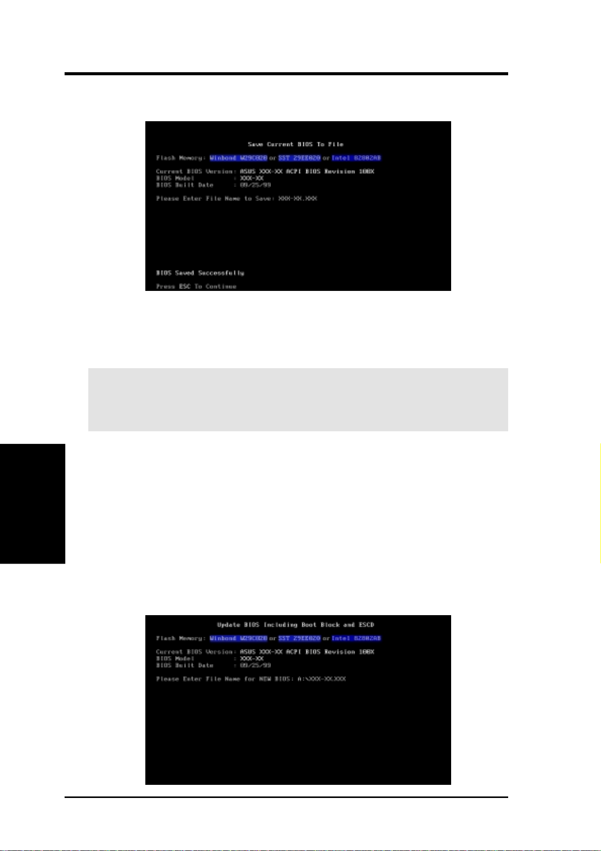
5. Select 1. Save Current BIOS to File from the Main menu and press
<Enter>. The Save Current BIOS To File screen appears.
6. T ype a filename and the path, for example, A:\XXX-XX.XXX and then
press <Enter>.
4.1.2 Updating BIOS Procedures
WARNING! Only update your BIOS if you have problems with your mother-
board and you know that the new BIOS revision will solve your problems. Careless updating can result in your motherboard having more problems!
4. BIOS SETUP
Updating BIOS
1. Download an updated ASUS BIOS file from the Internet (WWW or
2. Boot from the disk you created earlier.
3. At the “A:\” prompt, type AFLASH and then press <Enter>.
4. At the Main Menu, type 2 and then press <Enter>. The Update BIOS
5. Type the filename of your new BIOS and the path, for example, A:\XXX-
FTP) (see ASUS CONTACT INFORMATION on page 3 for details)
and save to the disk you created earlier.
Including Boot Block and ESCD screen appears.
XX.XXX, and then press <Enter>.
NOTE: To cancel this operation, press <Enter>.
ASUS CUPLE-VM User’s Manual38
Page 39
4. BIOS SETUP
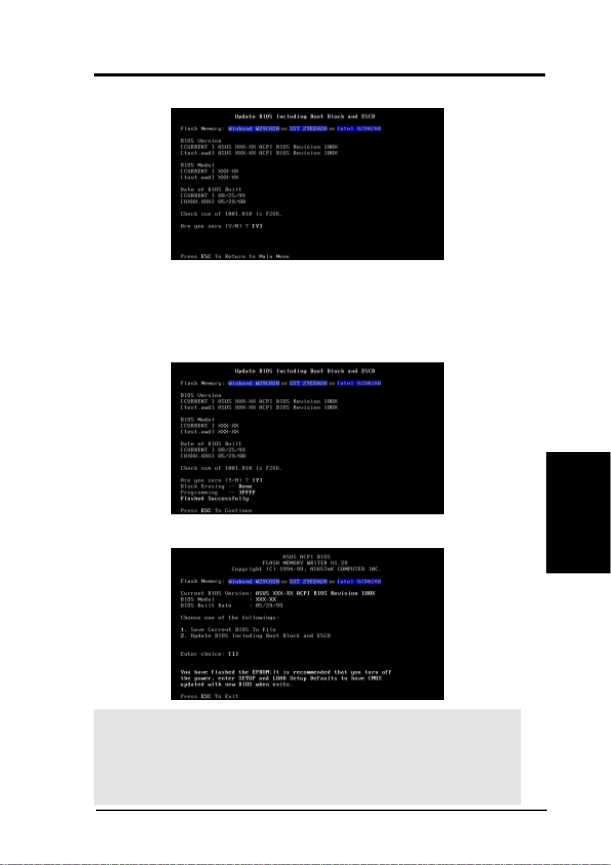
6. When prompted to confirm the BIOS update, press Y to start the update.
7. The utility starts to program the new BIOS information into the flash
ROM. The boot block will be updated automatically only when necessary. This will minimize the chance that a failed update will prevent
your system from booting up. When the programming is finished, Flashed
Successfully will be displayed.
8. Follow the onscreen instructions to continue.
WARNING! If you encounter problems while updating the new BIOS, DO NOT
turn off your system since this might prevent your system from booting up. Just
repeat the process, and if the problem still persists, update the original BIOS file
you saved to disk above. If the Flash Memory Writer utility was not able to
successfully update a complete BIOS file, your system may not be able to boot
up. If this happens, your system will need servicing.
ASUS CUPLE-VM User’s Manual 39
Updating BIOS
4. BIOS SETUP
Page 40

4.2 BIOS Setup Program
This motherboard supports a programmable EEPROM that can be updated using
the provided utility as described in 4.1 Managing and Updating Your BIOS.
The utility is used if you are installing a motherboard, reconfiguring your system,
or prompted to “Run Setup”. This section describes how to configure your system
using this utility.
Even if you are not prompted to use the Setup program, at some time in the future
you may want to change the configuration of your computer. For example, you
may want to enable the Security Password Feature or make changes to the power
management settings. It will then be necessary to reconfigure your system using
the BIOS Setup program so that the computer can recognize these changes and
record them in the CMOS RAM of the EEPROM.
The EEPROM on the motherboard stores the Setup utility. When you start up the
computer, the system provides you with the opportunity to run this program. This
appears during the Power-On Self Test (POST). Press <Delete> to call up the Setup
utility . If you are a little bit late in pressing the mentioned key, POST will continue
with its test routines, thus preventing you from calling up Setup. If you still need to
call Setup, restart the system by pressing <Ctrl> + <Alt> + <Delete>, or by pressing the Reset button on the system chassis. You can also restart by turning the
4. BIOS SETUP
system off and then back on again. But do so only if the first two methods fail.
4. BIOS SETUP
The Setup program has been designed to make it as easy to use as possible. It is a
menu-driven program, which means you can scroll through the various sub-menus
and make your selections among the predetermined choices.
To access the BIOS Setup program, press the <Delete> key after
the computer has run through its POST.
NOTE: Because the BIOS software is constantly being updated, the following
BIOS screens and descriptions are for reference purposes only and may not reflect your BIOS screens exactly.
Program Information
ASUS CUPLE-VM User’s Manual40
Page 41

4. BIOS SETUP
4.2.1 BIOS Menu Bar
The top of the screen has a menu bar with the following selections:
MAIN Use this menu to make changes to the basic system configuration.
ADVANCED Use this menu to enable and make changes to the advanced
features.
POWER Use this menu to configure and enable Power Management
features.
BOOT Use this menu to configure the default system device used to lo-
cate and load the Operating System.
EXIT Use this menu to exit the current menu or specify how to exit the
Setup program.
To access the menu bar items, press the right or left arrow key on the keyboard
until the desired item is highlighted.
4.2.2 Legend Bar
At the bottom of the Setup screen you will notice a legend bar. The keys in the
legend bar allow you to navigate through the various setup menus. The following
table lists the keys found in the legend bar with their corresponding alternates and
Menu Introduction
functions.
Navigation Key(s) Function Description
<F1> or <Alt + H> Displays the General Help screen from anywhere in the BIOS
<Esc> Jumps to the Exit menu or returns to the main menu from a sub-
← or → (keypad arrow) Selects the menu item to the left or right
↑ or ↓ (keypad arrow) Moves the highlight up or down between fields
- (minus key) Scrolls backward through the values for the highlighted field
+ (plus key) or spacebar Scrolls forward through the values for the highlighted field
<Enter> Brings up a selection menu for the highlighted field
<Home> or <PgUp> Moves the cursor to the first field
<End> or <PgDn> Moves the cursor to the last field
Setup
menu
4. BIOS SETUP
<F5> Resets the current screen to its Setup Defaults
<F10> Saves changes and exits Setup
ASUS CUPLE-VM User’s Manual 41
Page 42
4. BIOS SETUP
General Help
In addition to the Item Specific Help window, the BIOS setup program also provides a General Help screen. This screen can be called up from any menu by simply pressing <F1> or the <Alt> + <H> combination. The General Help screen lists
the legend keys with their corresponding alternates and functions.
Saving Changes and Exiting the Setup Program
See 4.7 Exit Menu for detailed information on saving changes and exiting the
setup program.
Scroll Bar
When a scroll bar appears to the right of a help window, it indicates that there is
more information to be displayed that will not fit in the window. Use <PgUp> and
<PgDn> or the up and down arrow keys to scroll through the entire help document. Press <Home> to display the first page, press <End> to go to the last page.
To exit the help window, press <Enter> or <Esc>.
Sub-Menu
4. BIOS SETUP
Take some time to familiarize yourself with each of the legend keys and their
corresponding functions. Practice navigating through the various menus and submenus. If you accidentally make unwanted changes to any of the fields, use the set
default hot key <F5>. While moving around through the Setup program, note that
explanations appear in the Item Specific Help window located to the right of each
menu. This window displays the help text for the currently highlighted field.
NOTE: The item heading in square brackets represents the default setting for
that field.
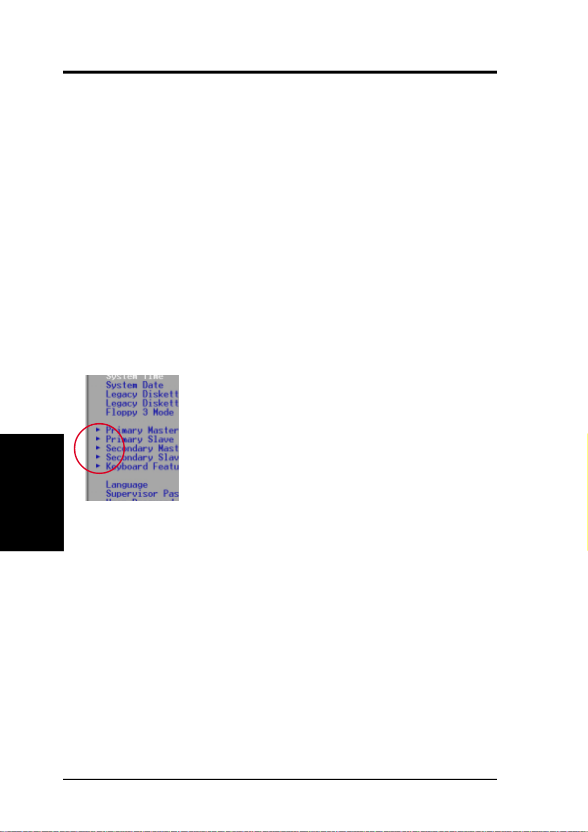
Note that a right pointer symbol (as shown in the left view)
appears to the left of certain fields. This pointer indicates that
a sub-menu can be launched from this field. A sub-menu contains additional options for a field parameter . To call up a submenu, simply move the highlight to the field and press <Enter>. The sub-menu will then immediately appear. Use the
legend keys to enter values and move from field to field within
a sub-menu just as you would within a menu. Use the <Esc>
key to return to the main menu.
Menu Introduction
ASUS CUPLE-VM User’s Manual42
Page 43
4. BIOS SETUP
4.3 Main Menu
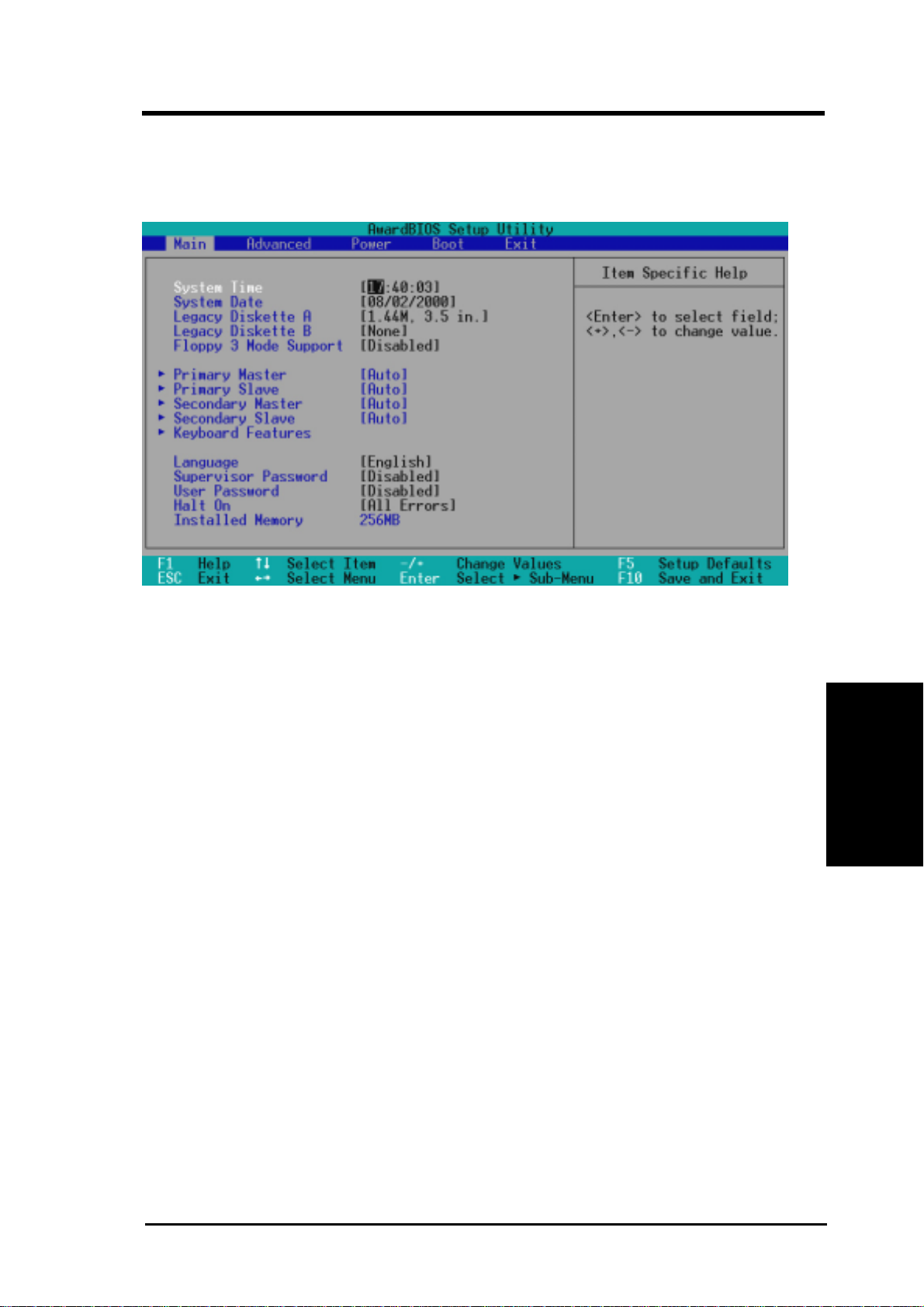
When the Setup program is accessed, the following screen appears:
Main Menu
System Time [XX:XX:XX]
Sets your system to the time that you specify (usually the current time). The format is hour, minute, second. Valid values for hour, minute and second are Hour:
(00 to 23), Minute: (00 to 59), Second: (00 to 59). Use the <Tab> or <Shift> +
<Tab> keys to move between the hour, minute, and second fields.
System Date [XX/XX/XXXX]
Sets your system to the date that you specify (usually the current date). The format
is month, day, year. Valid values for month, day, and year are Month: (1 to 12),
Day: (1 to 31), Year: (100 year range). Use the <Tab> or <Shift> + <Tab> keys to
move between the month, day, and year fields.
Legacy Diskette A [1.44M, 3.5 in.], Legacy Diskette B [None]
Sets the type of floppy drives installed. Configuration options: [None] [360K,
5.25 in.] [1.2M , 5.25 in.] [720K , 3.5 in.] [1.44M, 3.5 in.] [2.88M, 3.5 in.]
Floppy 3 Mode Support [Disabled]
This is required to support older Japanese floppy drives. Floppy 3 Mode support will allow reading and writing of 1.2MB (as opposed to 1.44MB) on a 3.5inch diskette. Configuration options: [Disabled] [Drive A] [Drive B] [Both]
4. BIOS SETUP
ASUS CUPLE-VM User’s Manual 43
Page 44
4. BIOS SETUP
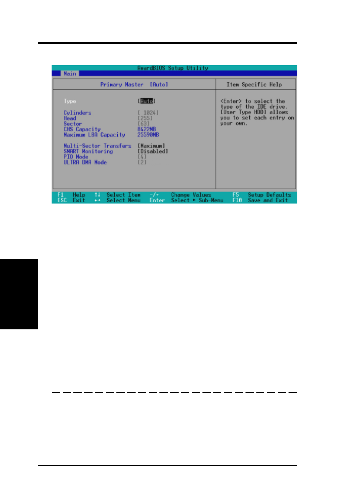
4.3.1 Primary & Secondary Master/Slave
NOTE: Before attempting to configure a hard disk drive, make sure you have
the configuration information supplied by the manufacturer of the drive. Incorrect settings may cause your system to not recognize the installed hard disk. To
allow the BIOS to detect the drive type automatically, select [Auto].
4. BIOS SETUP
Type [Auto]
Select [Auto] to automatically detect an IDE hard disk drive. If automatic detection is successful, the correct values will be filled in for the remaining fields on
this sub-menu. If automatic detection fails, your hard disk drive may be too old or
too new. You can try updating your BIOS or enter the IDE hard disk drive parameters manually.
NOTE: After the IDE hard disk drive information has been entered into BIOS,
new IDE hard disk drives must be partitioned (such as with FDISK) and then
formatted before data can be read from and write on. Primary IDE hard disk
drives must have its partition set to active (also possible with FDISK).
Other options for the Type field are:
Master/Slave Drives
[None] - to disable IDE devices
ASUS CUPLE-VM User’s Manual44
Page 45
4. BIOS SETUP
IMPORT ANT: If your hard disk was already formatted on an older previous system,
incorrect parameters may be detected. You will need to enter the correct parameters
manually or use low-level format if you do not need the data stored on the hard disk.
If the parameters listed differ from the ones used when the disk was formatted, the
disk will not be readable. If the auto-detected parameters do not match the ones that
should be used for your disk, you should enter the correct ones manually by setting
[User Type HDD].
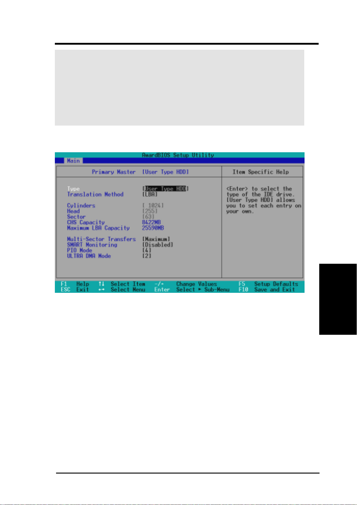
[User Type HDD]
Master/Slave Drives
Manually enter the number of cylinders, heads and sectors per track for your drive.
Refer to your drive documentation or look on the drive for this information. If no
drive is installed or if you are removing a drive and not replacing it, select [None].
Translation Method [LBA]
Select the hard disk drive type in this field. When Logical Block Addressing is enabled, 28-bit addressing of the hard drive is used without regard for cylinders, heads,
or sectors. Note that LBA Mode is necessary for drives with greater than 504MB in
storage capacity. Configuration options: [LBA] [LARGE] [Normal] [Match Partition T able] [Manual]
Cylinders
This field configures the number of cylinders. Refer to your drive documentation to
determine the correct value to enter into this field. NOTE: To make changes to this
field, the Type field must be set to [User Type HDD] and the Translation Method
field must be set to [Manual].
4. BIOS SETUP
ASUS CUPLE-VM User’s Manual 45
Page 46

4. BIOS SETUP
Head
This field configures the number of read/write heads. Refer to your drive documentation to determine the correct value to enter into this field. NOTE: T o make changes
to this field, the Type field must be set to [User Type HDD] and the Translation
Method field must be set to [Manual].
Sector
This field configures the number of sectors per track. Refer to your drive documentation to determine the correct value to enter into this field. NOTE: T o make changes
to this field, the Type field must be set to [User Type HDD] and the Translation
Method field must be set to [Manual].
CHS Capacity
This field shows the drive’s maximum CHS capacity calculated automatically by
the BIOS from the drive information you entered.
Maximum LBA Capacity
This field shows the drive’s maximum LBA capacity calculated automatically by
the BIOS from the drive information you entered.
Multi-Sector Transfers [Maximum]
This option automatically sets the number of sectors per block to the highest number
supported by the drive. This field can also be configured manually. Note that when
this field is automatically configured, the set value may not always be the fastest
value for the drive. Refer to the documentation that came with your hard drive to
4. BIOS SETUP
determine the optimal value and set it manually. NOTE: To make changes to this
field, the Type field must be set to [User Type HDD]. Configuration options: [Dis-
abled] [2 Sectors] [4 Sectors] [8 Sectors] [16 Sectors] [32 Sectors] [Maximum]
SMART Monitoring [Disabled]
This allows the enabling or disabling of the S.M.A.R.T. (Self-Monitoring, Analysis
and Reporting Technology) system which utilizes internal hard disk drive monitoring technology. This feature is normally disabled because system resources used in
this feature may decrease system performance. Configuration options: [Disabled]
[Enabled]
PIO Mode [4]
This option lets you set a PIO (Programmed Input/Output) mode for the IDE device.
Modes 0 through 4 provide successively increased performance. Configuration options: [0] [1] [2] [3] [4]
Master/Slave Drives
Ultra DMA Mode [Disabled]
Ultra DMA capability allows improved transfer speeds and data integrity for compatible IDE devices. Set to [Disabled] to suppress Ultra DMA capability . NOTE: To
make changes to this field, the Type field must be set to [User Type HDD]. Configu-
ration options: [0] [1] [2] [3] [4] [Disabled]
ASUS CUPLE-VM User’s Manual46
Page 47
4. BIOS SETUP
Other options for “Type:” are:
[CD-ROM] - for IDE CD-ROM drives
[LS-120] - for LS-120 compatible floppy disk drives
[ZIP-100] - for ZIP-100 compatible disk drives
[MO] - for IDE magneto optical disk drives
[Other ATAPI Device] - for IDE devices not listed here
After using the legend keys to make your selections on this sub-menu, press the
<Esc> key to exit back to the Main menu. When the Main menu appears, you will
notice that the drive size appear in the field for the hard disk drive that you just
configured.
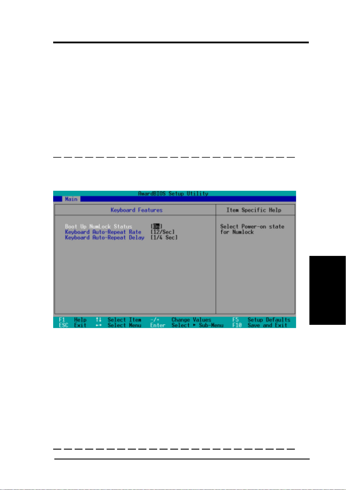
4.3.2 Keyboard Features
Main Menu
4. BIOS SETUP
Boot Up NumLock Status [On]
This field enables users to activate the Number Lock function upon system boot.
Configuration options: [Off] [On]
Keyboard Auto-Repeat Rate [12/Sec]
This controls the speed at which the system registers repeated keystrokes. Options
range from 6 to 30 characters per second. Configuration options: [6/Sec] [8/Sec]
[10/Sec] [12/Sec] [15/Sec] [20/Sec] [24/Sec] [30/Sec]
Keyboard Auto-Repeat Delay [1/4 Sec]
This field sets the time interval for displaying the first and second characters. Configuration options: [1/4 Sec] [1/2 Sec] [3/4 Sec] [1 Sec]
ASUS CUPLE-VM User’s Manual 47
Page 48
4. BIOS SETUP
Language [English]
This allows selection of the BIOS’ displayed language. Currently only English is available.
Supervisor Password [Disabled] / User Password [Disabled]
These fields allow you to set the passwords. To set the password, highlight the appropriate field and press <Enter>. T ype in a password and press <Enter>. You can type up
to eight alphanumeric characters. Symbols and other keys are ignored. To confirm the
password, type the password again and press the <Enter>. The password is now set to
[Enabled]. This password allows full access to the BIOS Setup menus. To clear the
password, highlight this field and press <Enter>. The same dialog box as above will
appear . Press <Enter> and the password will be set to [Disabled].
A Note about Passwords
The BIOS Setup program allows you to specify passwords in the Main menu. The passwords control access to the BIOS during system startup. The passwords are not case sensitive. In other words, it makes no difference whether you enter a password using upper or
lowercase letters. The BIOS Setup program allows you to specify two separate passwords:
a Supervisor password and a User password. When disabled, anyone may access all BIOS
Setup program functions. When enabled, the Supervisor password is required for entering
the BIOS Setup program and having full access to all configuration fields.
Forgot the Password?
If you forgot the password, you can clear the password by erasing the CMOS Real Time
Clock (R TC) RAM. The RAM data containing the password information is powered by the
onboard button cell battery. To erase the RTC RAM: (1) Unplug your computer.
4. BIOS SETUP
(2) Remove the 3V CR2032 onboard battery. (3) Replace the battery, or short
circuit R139. (4) Turn ON your computer, (5) Hold down <Delete> during bootup and
enter BIOS setup to re-enter any new user preferences.
Halt On [All Errors]
This field determines which types of errors will cause the system to halt. Configuration options: [All Errors] [No Error] [All but Keyboard] [All but Disk] [All but
Disk/Keyboard]
CUPLE-VM
CUPLE-VM Clear RTC RAM
R139
Short solder points
to Clear CMOS
Main Menu
Installed Memory [XXX MB]
This display-only field displays the amount of conventional memory detected by the
system during bootup. You do not need to make changes to this field.
ASUS CUPLE-VM User’s Manual48
Page 49
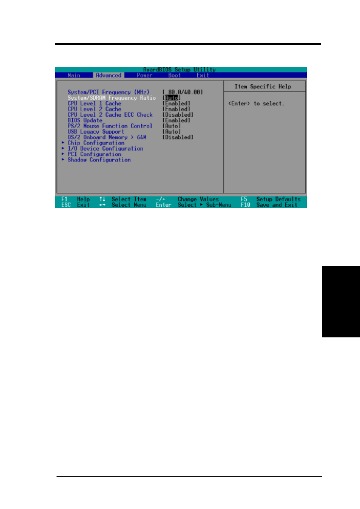
4. BIOS SETUP
4.4 Advanced Menu
Advanced Menu
System/PCI Frequency [MHz]
This field displays the frequency ratio between the System (Front Side Bus)
and the PCI bus. The ratios displayed in this field are auto detected by the
system.
System/DRAM Frequency Ratio [Auto]
This field offers 3 settings for the frequency ratio between the System (Front
Side Bus) and SDRAM. If the FSB Frequency is 66MHz, then the field
offers three configuration options: [Auto] [1/1] [2/3]. If the FSB Frequency
is 100MHz, then the field offers three configuration options: [Auto] [3/2]
[3/4]. If the FSB Frequency is 133MHz, then the field offers three configuration options: [Auto] [1/1] [4/3].
4. BIOS SETUP
CPU Level 1 Cache, CPU Level 2 Cache [Enabled]
These field lets you choose from the default of [Enabled] or choose [Disabled] to turn on or off the CPU’s Level 1 and Level 2 built-in cache. Con-
figuration options: [Disabled] [Enabled]
CPU Level 2 Cache ECC Check [Disabled]
This function controls the ECC capability in the CPU level 2 cache. Configuration options: [Disabled] [Enabled]
BIOS Update [Enabled]
This functions as an update loader integrated into the BIOS to supply the
processor with the required data. In the default position of [Enabled], the
BIOS will load the update on all processors during system bootup. Configuration options: [Disabled] [Enabled]
ASUS CUPLE-VM User’s Manual 49
Page 50

4. BIOS SETUP
PS/2 Mouse Function Control [Auto]
The default of [Auto] allows the system to detect a PS/2 mouse on startup. If detected, IRQ12 will be used for the PS/2 mouse. IRQ12 will be reserved for expansion cards only if a PS/2 mouse is not detected. [Enabled] will always reserve IRQ12,
whether on startup a PS/2 mouse is detected or not. Configuration options: [Enabled] [Auto]
USB Legacy Support [Auto]
This motherboard supports Universal Serial Bus (USB) devices. The default of [Auto]
allows the system to detect a USB device on startup. If detected, the USB controller
will be enabled. If not detected, the USB controller will be disabled. When this field
is set to [Disabled], the USB controller is disabled no matter whether you are using
a USB device or not. Configuration options: [Disabled] [Enabled] [Auto]
OS/2 Onboard Memory > 64M [Disabled]
When using OS/2 operating systems with installed DRAM of greater than 64MB,
you need to set this option to [Enabled]; otherwise, leave this on [Disabled]. Configuration options: [Disabled] [Enabled]
4. BIOS SETUP
Advanced Menu
ASUS CUPLE-VM User’s Manual50
Page 51
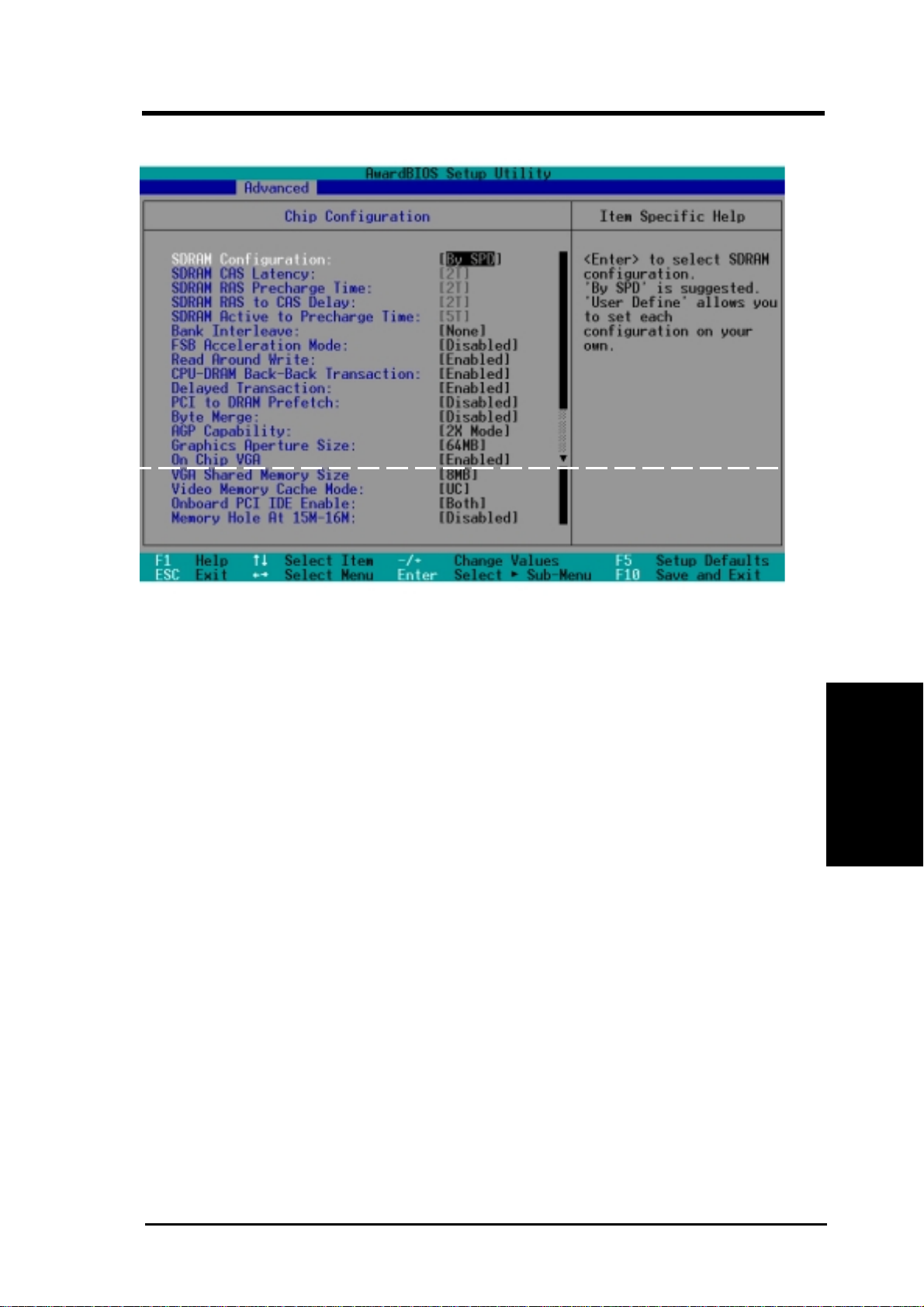
4. BIOS SETUP
4.4.1 Chip Configuration
SDRAM Configuration [By SPD]
This sets the optimal timings for SDRAM related fields, depending on the memory
JumperFree Mode
modules that you are using. Default setting is [By SPD], which configures the subsequent 3 items by reading the contents in the SPD (Serial Presence Detect) device.
The EEPROM on the memory module stores critical parameter information about
the module, such as memory type, size, speed, voltage interface, and module banks.
Configuration options: [User Define] [7ns(143MHz)] [8ns(125MHz)] [By SPD]
SDRAM CAS Latency
This controls the latency between the SDRAM read command and the time that the
data actually becomes available. NOTE: This field will only be adjustable when
SDRAM Configuration is set to [User Define].
SDRAM RAS Precharge Time
This controls the idle clocks after issuing a precharge command to the SDRAM.
NOTE: This field will only be adjustable when SDRAM Configuration is set to
[User Define].
(Scroll down to see more items as shown.)
4. BIOS SETUP
SDRAM RAS to CAS Delay
This controls the latency between the SDRAM active command and the read/write
command. NOTE: This field will only be adjustable when SDRAM Configuration
is set to [User Define].
ASUS CUPLE-VM User’s Manual 51
Page 52

4. BIOS SETUP
SDRAM Active to Precharge Time
NOTE: This field will only be adjustable when SDRAM Configuration is set to
[User Define].
Bank Interleave [Enabled]
Configuration options: [Enabled] [Disabled]
FSB Acceleration Time [Disabled]
Configuration options: [Enabled] [Disabled]
Read Around Write [Enabled]
Configuration options: [Enabled] [Disabled]
CPU-DRAM Back-Back Transaction [Enabled]
Configuration options: [Enabled] [Disabled]
PCI to DRAM Prefetch [Enabled]
Configuration options: [Disabled] [Enabled]
Byte Merge [Disabled]
To optimize the data transfer on PCI, this merges a sequence of individual memory
writes (bytes or words) into a single 32-bit block of data. However, byte merging
may only be done when the bytes within a data phase are in a prefetchable address
range. Configuration options: [Disabled] [Enabled]
AGP Capability [4X Mode]
4. BIOS SETUP
Configuration options: [2X Mode] [4X Mode]
Graphics Aperture Size [64MB]
This feature allows you to select the size of mapped memory for AGP graphic data.
Configuration options: [4MB] [8MB] [16MB] [32MB] [64MB] [128MB] [256MB]
On Chip VGA [Enabled]
Configuration options:
VGA Shared Memory Size [8MB]
Configuration options: [2MB] [4MB] [8MB]
Video Memory Cache Mode [UC]
USWC (uncacheable, speculative write combining) is a new cache technology for
the video memory of the processor. It can greatly improve the display speed by
caching the display data. You must set this to UC (uncacheable) if your display card
cannot support this feature; otherwise your system may not boot. Configuration options: [UC] [USWC]
Chip Configuration
[Disabled] [Enabled]
Onboard PCI IDE Enable [Both]
Configuration options: [Both] [Primary] [Secondary] [Disabled]
ASUS CUPLE-VM User’s Manual52
Page 53

4. BIOS SETUP
Onboard PCI Audio Enable [Enabled]
This field appears only if the Creative Audio Controller is available. Configuration
options: [Enabled] [Disabled]
Memory Hole At 15M-16M [Disabled]
Configuration options: [Enabled] [Disabled]
Chip Configuration
4. BIOS SETUP
ASUS CUPLE-VM User’s Manual 53
Page 54
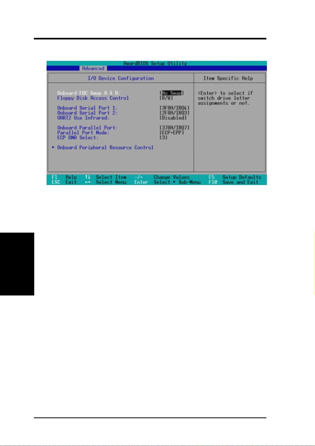
4. BIOS SETUP
4.4.2 I/O Device Configuration
Onboard FDC Swap A & B [No Swap]
This field allows you to reverse the hardware drive letter assignments of your floppy
disk drives. Configuration options: [No Swap] [Swap AB]
Floppy Disk Access Control [R/W]
4. BIOS SETUP
When set to [Read Only], this field protects files from being copied to floppy disks
by allowing reads from the floppy disk drive but not writes. The setup default [R/W]
allows both reads and writes. Configuration options: [R/W] [Read Only]
Onboard Serial Port 1 [3F8H/IRQ4]
Onboard Serial Port 2 [2F8H/IRQ3]
These fields allow you to set the addresses for the onboard serial connectors. Serial
Port 1 and Serial Port 2 must have different addresses. Configuration options: [3F8H/
IRQ4] [2F8H/IRQ3] [3E8H/IRQ4] [2E8H/IRQ10] [Disabled]
UART2 Use Infrared [Disabled]
When enabled, this field activates the onboard standard infrared feature and sets
the second serial UART to support the infrared module connector on the motherboard. If your system already has a second serial port connected to the onboard
COM2 connector, it will no longer work if you enable the infrared feature. See
Standard and Consumer Infrared Module Connector in 3.8 External Connec-
tors. Configuration options: [Disabled] [Enabled]
ASUS CUPLE-VM User’s Manual54
Page 55

4. BIOS SETUP
Onboard Parallel Port [378H/IRQ7]
This field sets the address of the onboard parallel port connector. If you disable this
feature, Parallel Port Mode and ECP DMA Select configurations will not be avail-
able. Configuration options: [Disabled] [378H/IRQ7] [278H/IRQ5]
Parallel Port Mode [ECP+EPP]
This field allows you to set the operation mode of the parallel port. [Normal] allows
normal-speed operation but in one direction only; [EPP] allows bidirectional parallel
port operation; [ECP] allows the parallel port to operate in bidirectional DMA mode;
[ECP+EPP] allows normal speed operation in a two-way mode. Configuration options: [Normal] [ECP] [EPP] [ECP+EPP]
ECP DMA Select [3]
This field allows you to configure the parallel port DMA channel for the selected ECP
mode. This selection is available only if you select [ECP] or [ECP+EPP] in Parallel
Port Mode above. Configuration options: [1] [3]
I/O Device Config
4. BIOS SETUP
ASUS CUPLE-VM User’s Manual 55
Page 56
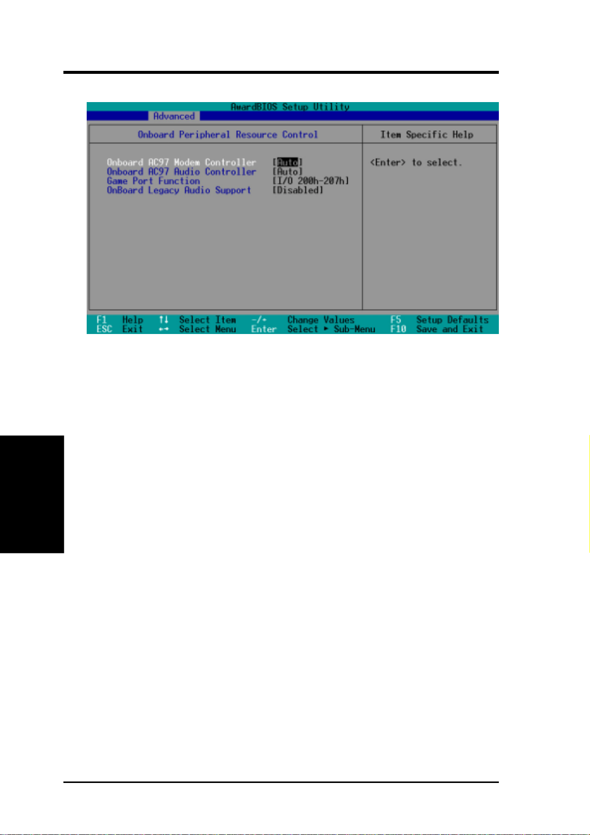
4. BIOS SETUP
Onboard Peripheral Resource Control
Onboard AC97 Modem Controller [Auto]
Onboard AC97 Audio Controller [Auto]
[Auto] allows the motherboard’s BIOS to detect whether you are using any net-
work/audio device. If a network/audio device is detected, the onboard network/audio controller will be enabled; if no network/audio device is detected, the onboard
4. BIOS SETUP
network/audio controller will be disabled. If you have conflicts with the onboard
network/audio controller, you may set the appropriate field to [Disabled]. Configuration options: [Enabled] [Disabled] [Auto]
Game Port Function [
Enable this field to use the game port. Configuration options:
[I/O (200h-207h)] [Disabled]
I/O (200h-207h)
]
I/O Device Config
ASUS CUPLE-VM User’s Manual56
Page 57
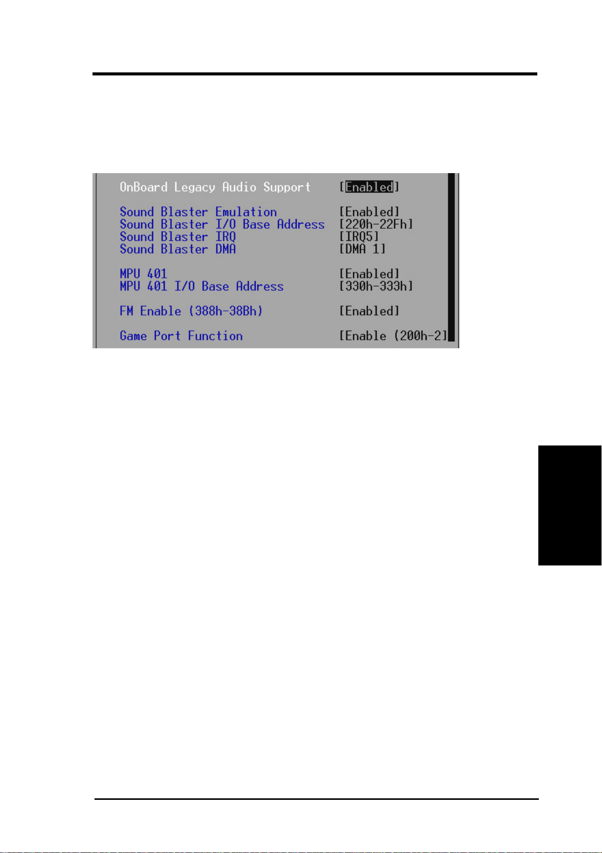
4. BIOS SETUP
Onboard Legacy Audio Support [Disabled]
The onboard chipset is integrated with a SoundBlaster Pro controller . To use it, you
must enable this field. Leave on the default setting [Disabled] if you want to use an
add-on audio device. NOTE: To display the rest of the setup items, this field must
be enabled (as shown below).
Sound Blaster Emulation [Disabled]
Select [Enabled] for this field if you want to use the Sound Blaster™ emulation
feature.
Sound Blaster I/O Base Address [220h-22Fh]
Sound Blaster IRQ [IRQ5]
I/O Device Config
Sound Blaster DMA [DMA 1]
These fields set the I/O address, IRQ, and DMA channel for the Sound Blaster™
feature.
MPU 401 [Enabled]
Enable this field if you want to use the MIDI device onboard.
MPU 401 I/O Base Address [300h-303h]
This sets the I/O address for the onboard MIDI device.
FM Enable (388h-38Bh) [Disabled]
This field enables or disables the FM modulation feature.
4. BIOS SETUP
ASUS CUPLE-VM User’s Manual 57
Page 58
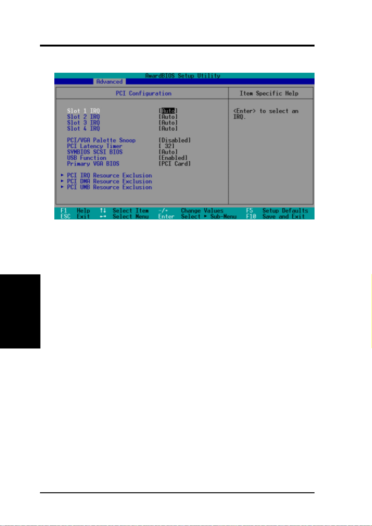
4. BIOS SETUP
4.4.3 PCI Configuration
Slot 1, Slot 2, Slot 3 Slot 4 IRQ [Auto]
These fields set how IRQ use is determined for each PCI slot. The default setting
for each field is [Auto], which utilizes auto-routing to determine IRQ use. Configuration options: [Auto] [NA] [3] [4] [5] [7] [9] [10] [11] [12] [14] [15]
4. BIOS SETUP
PCI/VGA Palette Snoop [Disabled]
Some nonstandard VGA cards, such as graphics accelerators or MPEG video cards,
may not show colors properly. The setting [Enabled] should correct this problem.
Otherwise, leave this on the default setting of [Disabled]. Configuration options:
[Disabled] [Enabled]
PCI Latency Timer [32]
Leave on default setting for best performance vs. stability.
SYMBIOS SCSI BIOS [Auto]
[Auto] allows the motherboard’s BIOS to detect whether you have a Symbios SCSI
card. If the Symbios SCSI card is detected, the motherboard’s Symbios BIOS will
be enabled; if no Symbios SCSI card is detected, the onboard Symbios SCSI BIOS
will be disabled.
PCI Configuration
[Disabled] will disable the motherboard’s Symbios SCSI BIOS so that the BIOS
on an add-on Symbios SCSI card can be used. If your Symbios SCSI card does not
have a BIOS, the Symbios SCSI card will not function. Configuration options: [Auto]
[Disabled]
ASUS CUPLE-VM User’s Manual58
Page 59
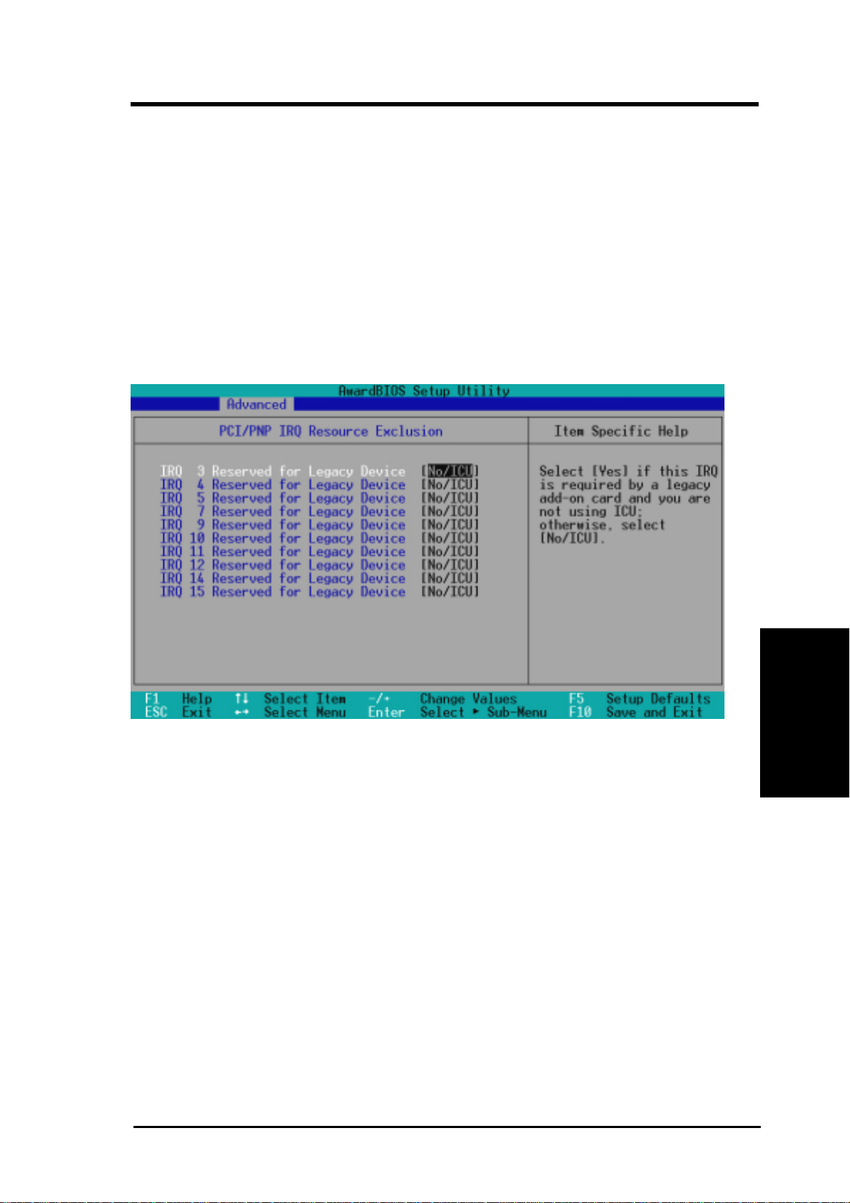
4. BIOS SETUP
USB Function [Enabled]
This motherboard supports Universal Serial Bus (USB) devices. Set to [Enabled] if
you want to use USB devices. Configuration options: [Disabled] [Enabled]
Primary VGA BIOS [PCI Card]
If your computer has a PCI VGA card and on-board VGA is available, this field
allows you to select which of the VGA devices will act as your primary graphics
controller. The default, [PCI Card], allows your PCI graphics card to take precedence when detected. [On-Board] uses on-board VGA as the primary graphics
controller. Configuration options: [PCI Card] [On-Board]
PCI/PNP IRQ Resource Exclusion
PCI Configuration
IRQ XX Reserved for Legacy Device [No/ICU]
These fields indicate whether or not the displayed IRQ for each field is being used
by an onboard legacy (non-PnP) device. The default value indicates either that the
displayed IRQ is not used or that ISA Configuration Utility (ICU) is being used to
determine if a legacy device is using that IRQ. Configuration options: [No/ICU]
[Yes]
4. BIOS SETUP
ASUS CUPLE-VM User’s Manual 59
Page 60
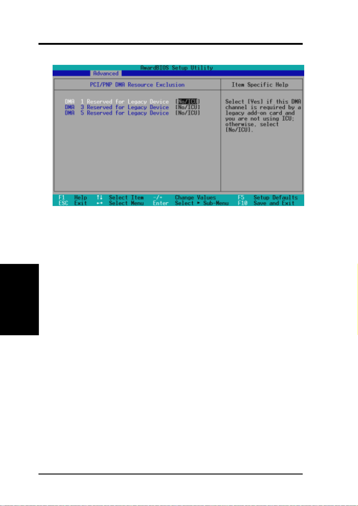
4. BIOS SETUP
PCI/PNP DMA Resource Exclusion
DMA x Reserved for Legacy Device [No/ICU]
These fields indicate whether or not the displayed DMA channel for each field is
being used by an onboard legacy (non-PnP) device. The default setting indicates
either that the displayed DMA channel is not used or an ICU is being used to determine if an ISA device is using that channel. Configuration options: [No/ICU] [Yes]
4. BIOS SETUP
PCI Configuration
ASUS CUPLE-VM User’s Manual60
Page 61
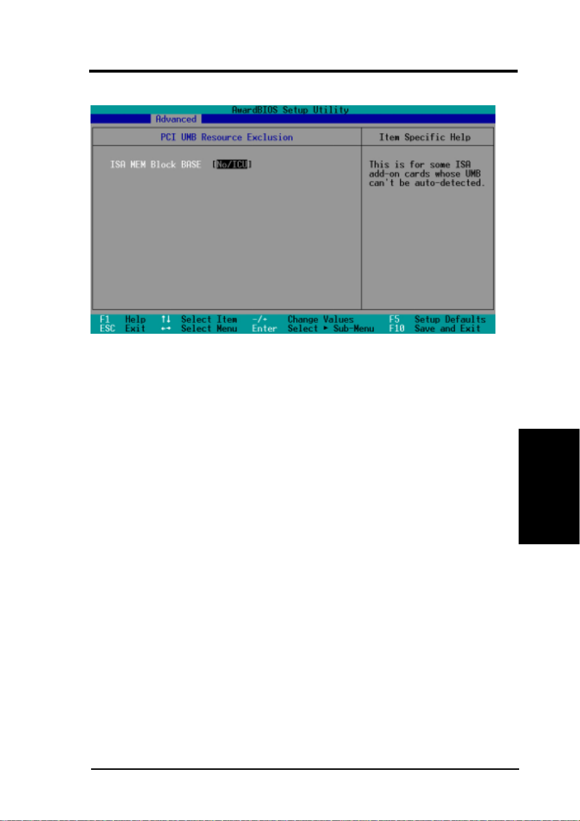
4. BIOS SETUP
PCI/PNP UMB Resource Exclusion
Reserved MEM Block BASE [No/ICU]
This field allows you to set the base address and block size of an onboard legacy ISA
device that uses any memory segment within the C800 and DFFF address range. If
you have such a device and you are not using an ICU to specify its address range,
select a base address from the six available options; the Reserved MEM Block
PCI Configuration
SIZE field will then appear for selecting the block size. If you have more than one
legacy device onboard that requires the use of this address range, you can increase
the block size to 8K, 16K, 32K, or 64K. If you are using an ICU to accomplish this
task, leave Reserved MEM Block BASE to its default setting of [No/ICU]. Configuration options: [No/ICU] [C800] [CC00] [D000] [D400] [D800] [DC00]
4. BIOS SETUP
ASUS CUPLE-VM User’s Manual 61
Page 62
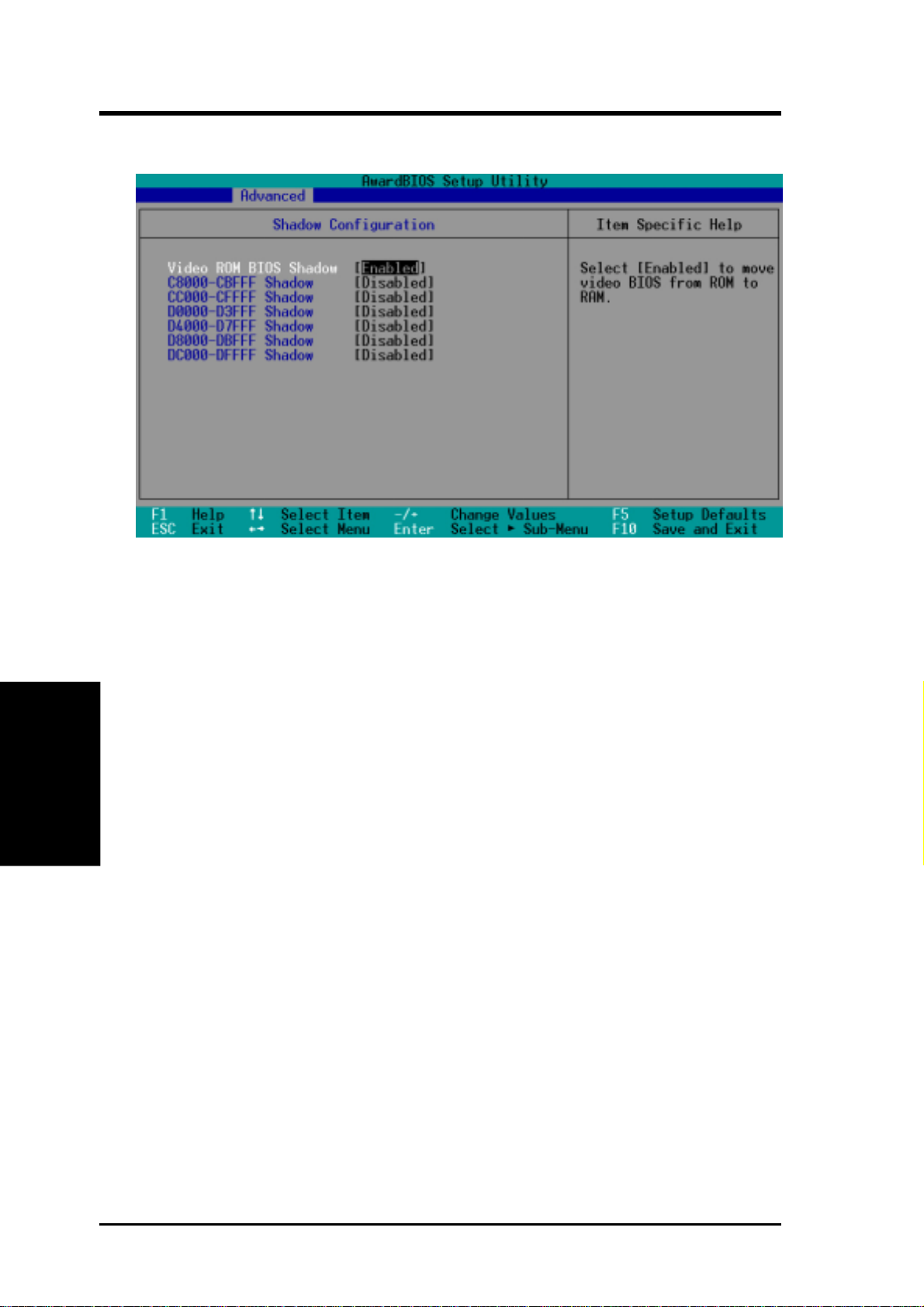
4. BIOS SETUP
4.4.4 Shadow Configuration
Video ROM BIOS Shadow [Enabled]
This field allows you to change the video BIOS location from ROM to RAM. Relocating to RAM enhances system performance, as information access is faster than
the ROM. Configuration options: [Disabled] [Enabled]
C8000-DFFFF Shadow [Disabled]
4. BIOS SETUP
These fields are used for shadowing other expansion card ROMs. If you install other
expansion cards with ROMs on them, you will need to know which addresses the
ROMs use to shadow them specifically. Shadowing a ROM reduces the memory
available between 640K and 1024K by the amount used for this purpose. Configuration options: [Disabled] [Enabled]
Shadow Configuration
ASUS CUPLE-VM User’s Manual62
Page 63
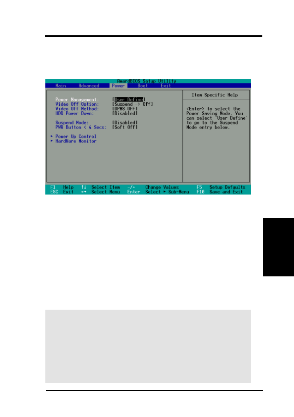
4. BIOS SETUP
4.5 Power Menu
The Power menu allows you to reduce power consumption. This feature turns off the
video display and shuts down the hard disk after a period of inactivity.
Power Management [User Define]
This option must be enabled to use any of the automatic power saving features. If
this menu item is set to [Disabled], power management features will not function
Power Menu
regardless of other field settings on this menu. The [User Define] option allows you
to make your own selections in the Power menu. When set to [Max Saving], system
power will be conserved to its greatest amount. The Suspend Mode field will then
be set to predefined value that ensures maximum power savings.
This field acts as the master control for the power management modes. [Max Saving] puts the system into power saving mode after a brief period of system inactivity; [Min Saving] is almost the same as [Max Saving] except that the system inactivity period is longer; [Disabled] disables the power saving features; [User Define]
allows you to set power saving options according to your preference. Configuration
options: [User Define] [Disabled] [Min Saving] [Max Saving]
4. BIOS SETUP
IMPORT ANT: Advanced Power Management (APM) should be installed to keep
the system time updated when the computer enters suspend mode activated by
the BIOS Power Management. For DOS environments, you need to add the
statement, DEVICE=C:\DOS\POWER.EXE, to your CONFIG.SYS file. For
Windows 3.x and Windows 95, you need to install Windows with the APM
feature. For Windows 98 and later, APM is automatically installed. A battery
and power cord icon labeled “Power Management” will appear in the “Control
Panel.” Choose “Advanced” in the Power Management Properties dialog box.
ASUS CUPLE-VM User’s Manual 63
Page 64

4. BIOS SETUP
Video Off Option [Suspend -> Off ]
This field determines when to activate the video off feature for monitor power management. Configuration options: [Always On] [Suspend -> Off]
Video Off Method [DPMS OFF]
This field defines the video off features. The DPMS (Display Power Management
System) feature allows the BIOS to control the video display card if it supports the
DPMS feature. [Blank Screen] only blanks the screen (use this for monitors without
power management or “green” features. If set up in your system, your screen saver
will not display with [Blank Screen] selected). [V/H SYNC+Blank] blanks the screen
and turns off vertical and horizontal scanning. Configuration options: [Blank Screen]
[V/H SYNC+Blank] [DPMS Standby] [DPMS Suspend] [DPMS OFF] [DPMS Reduce ON]
HDD Power Down [Disabled]
Shuts down any IDE hard disk drives in the system after a period of inactivity as
set in this user-configurable field. This feature does not affect SCSI hard drives.
Configuration options: [Disabled] [1 Min] [2 Min] [3 Min]...[15 Min]
Suspend Mode [Disabled]
Sets the time period before the system goes into suspend mode. Configuration
options: [Disabled] [30 Sec] [1 Min]... [40 Min]
PWR Button < 4 Secs [Soft Off]
4. BIOS SETUP
When set to [Soft off], the ATX switch can be used as a normal system power-off
button when pressed for less than 4 seconds. [Suspend] allows the button to have a
dual function where pressing less than 4 seconds will place the system in sleep
mode. Regardless of the setting, holding the ATX switch for more than 4 seconds
will power off the system. Configuration options: [Soft off] [Suspend]
Power Menu
ASUS CUPLE-VM User’s Manual64
Page 65
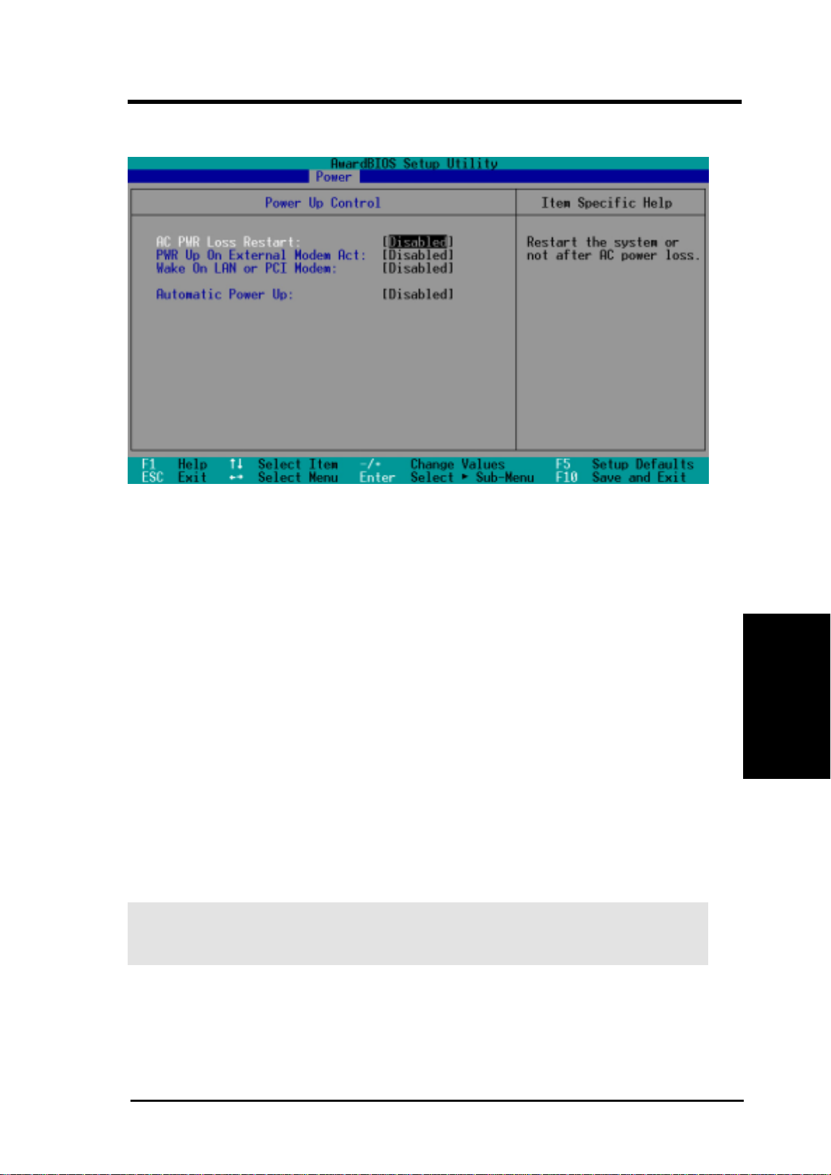
4. BIOS SETUP
4.5.1 Power Up Control
AC PWR Loss Restart [Disabled]
This allows you to set whether you want your system to reboot after the power has
been interrupted. [Disabled] leaves your system of f and [Enabled] reboots your sys-
tem. [Previous State] sets your system back to the state it is before the power interruption. Configuration options: [Disabled] [Enabled] [Previous State]
Power Up Control
PWR Up On External Modem Act [Disabled]
This setting powers up the computer whenever the external modem receives a call
while the computer is in Soft-off mode. NOTE: The computer cannot receive or
transmit data until the computer and applications are fully running. Thus connection
cannot be made on the first try. Turning an external modem off and then back on
while the computer is off causes an initialization string that will also cause the system to power on. Configuration options: [Disabled] [Enabled]
Wake On LAN or PCI Modem [Disabled]
Wake-On-LAN/PCI Modem allows your computer to be booted from another computer via a network by sending a wake-up frame or signal. Configuration options:
[Disabled] [Enabled]
4. BIOS SETUP
IMPORTANT: This feature requires an optional network interface card with W ake-
On-LAN and an ATX power supply with at least 720mA +5V standby power.
ASUS CUPLE-VM User’s Manual 65
Page 66

4. BIOS SETUP
Automatic Power Up [Disabled]
This allows an unattended or automatic system power up. You may configure your
system to power up at a certain time of the day by selecting [Everyday] or at a
certain time and day by selecting [By Date]. NOTE: Automatic Power Up will not
work if the system is powered down by operating systems, such as W indows 98, that
have ACPI support enabled. Configuration options: [Disabled] [Everyday] [By Date]
4. BIOS SETUP
Power Up Control
ASUS CUPLE-VM User’s Manual66
Page 67
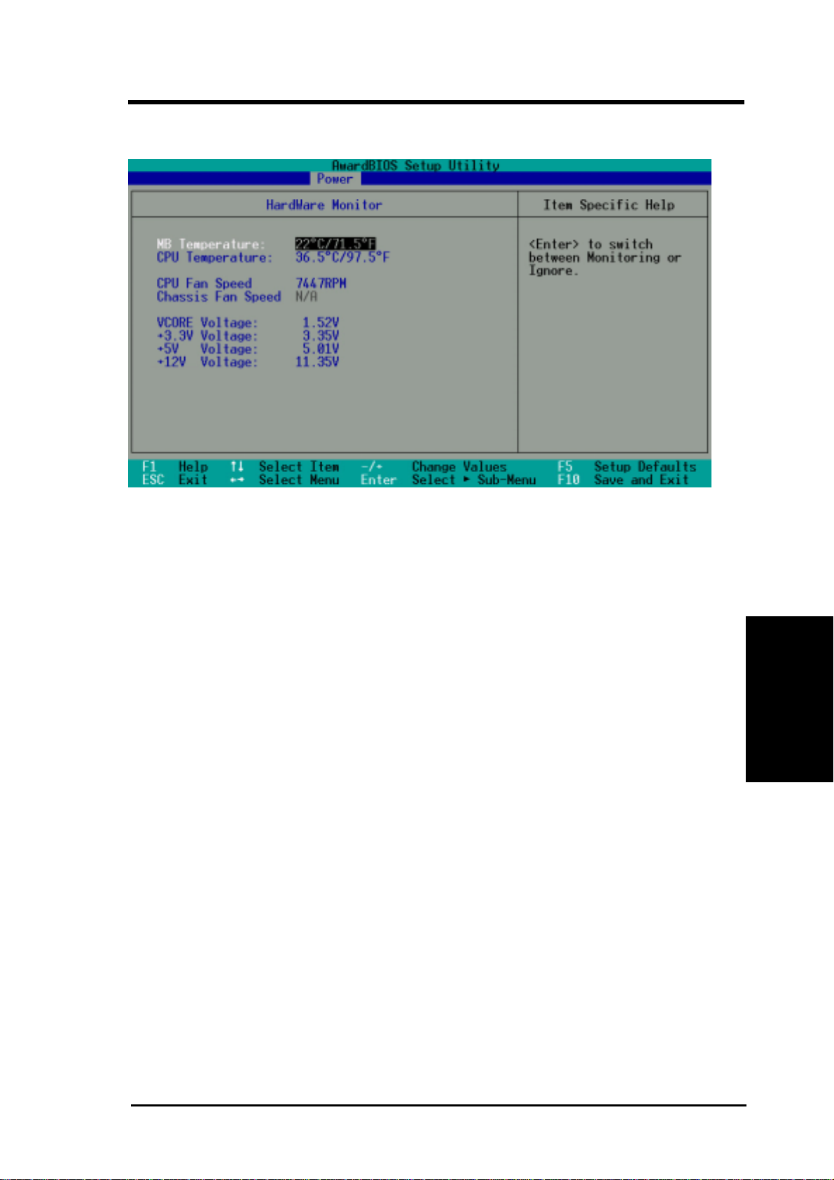
4. BIOS SETUP
4.5.2 Hardware Monitor
MB Temperature [xxxC/xxxF]
CPU Temperature [xxxC/xxxF]
The onboard hardware monitor is able to detect the MB (motherboard) and CPU
temperatures. Set to [Ignore] only if necessary.
Hardware Monitor
CPU Fan Speed [xxxxRPM]
Chassis Fan Speed [xxxxRPM]
The onboard hardware monitor is able to detect the CPU fan speed and the chassis
fan speed in rotations per minute (RPM). The presence of the fans is automatically
detected. Set to [Ignore] only if necessary.
VCORE Voltage, +3.3V Voltage, +5V Voltage, +12V Voltage [xx.xxV]
The onboard hardware monitor is able to detect the voltage output by the onboard
voltage regulators. Set to [Ignore] only if necessary.
NOTE: If any of the monitored items is out of range, an error message will appear:
“Hardware Monitor found an error. Enter Power setup menu for details”. You will
then be prompted to “Press F1 to continue, DEL to enter SETUP”.
4. BIOS SETUP
ASUS CUPLE-VM User’s Manual 67
Page 68
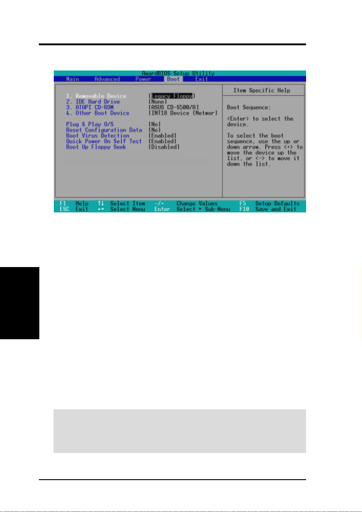
4. BIOS SETUP
4.6 Boot Menu
Boot Sequence
The Boot menu allows you to select among the four possible types of boot devices
listed using the up and down arrow keys. By using the <+> or <Space> key, you can
promote devices and by using the <-> key, you can demote devices. Promotion or
demotion of devices alters the priority which the system uses to search for a boot
4. BIOS SETUP
device on system power up. Configuration fields include Removable Devices, IDE
Hard Drive, ATAPI CD-ROM, and Other Boot Device.
Removable Device [Legacy Floppy]
Configuration options: [Disabled] [Legacy Floppy] [LS120] [ZIP] [ATAPI MO]
IDE Hard Drive
This field allows you to select which IDE hard disk drive to use in the boot sequence. Pressing [Enter] will show the product IDs of all connected IDE hard disk
drives.
ATAPI CD-ROM
This field allows you to select which ATAPI CD-ROM drive to use in the boot
sequence. Pressing [Enter] will show the product IDs of all your connected ATAPI
CD-ROM drives.
Boot Menu
IMPORTANT: Make sure the ATAPI CD-ROM drive that you want to use in the
boot sequence is connected to either the PRIMARY or SECONDARY IDE connectors, not to the ATA100 connectors. Currently, the Promise® Ultra DMA/100
chip does not support this feature.
ASUS CUPLE-VM User’s Manual68
Page 69

4. BIOS SETUP
Other Boot Device Select [INT18 Device (Network)]
Configuration options: [Disabled] [SCSI/Onboard ATA Boot Device] [INT18 Device (Network)] [LANDesk (R) Service Agent]
Plug & Play O/S [No]
This field allows you to use a Plug-and-Play (PnP) operating system to configure
the PCI bus slots instead of using the BIOS. When [Yes] is selected, interrupts may
be reassigned by the OS. When a non-PnP OS is installed or you want to prevent
reassigning of interrupt settings, select the default setting of [No]. Configuration
options: [No] [Yes]
Reset Configuration Data [No]
The Extended System Configuration Data (ESCD) contain information about nonPnP devices. It can also hold the complete record of how the system was configured
the last time it was booted. Select [Yes] only if you want to clear these data during
the Power-On Self Test (POST). Configuration options: [No] [Yes]
Boot Virus Detection [Enabled]
This field allows you to set boot virus detection, ensuring a virus-free boot sector.
The system halts and displays a warning message when it detects a virus. If this
occurs, you can either allow the operation to continue or use a virus-free bootable
floppy disk to restart and investigate your system. Configuration options: [Disabled]
[Enabled]
Boot Menu
Quick Power On Self Test [Enabled]
This field speeds up the Power-On-Self Test (POST) routine by skipping retesting a
second, third, and fourth time. Configuration options: [Disabled] [Enabled]
Boot Up Floppy Seek [Disabled]
When enabled, the BIOS will seek the floppy disk drive to determine whether the
drive has 40 or 80 tracks. Configuration options: [Disabled] [Enabled]
4. BIOS SETUP
ASUS CUPLE-VM User’s Manual 69
Page 70
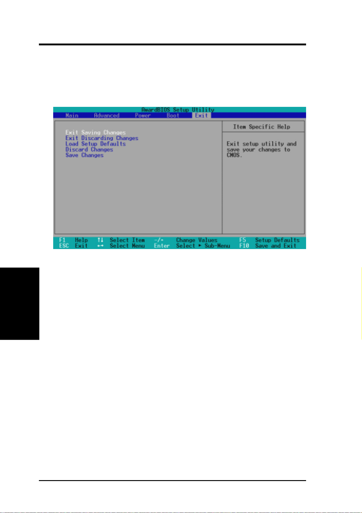
4. BIOS SETUP
4.7 Exit Menu
Once you have made all of your selections from the various menus in the Setup
program, you should save your changes and exit Setup. Select Exit from the menu
bar to display the following menu:
NOTE: Pressing <Esc> does not exit this menu. You must select one of the options
4. BIOS SETUP
from this menu or <F10> from the legend bar to exit this menu.
Exit Saving Changes
Once you are finished making your selections, choose this option from the Exit
menu to ensure the values you selected are saved to the CMOS RAM. The CMOS
RAM is sustained by an onboard backup battery and stays on even when the PC is
turned off. Once this option is selected, a confirmation is asked. Select [Yes] to
save changes and exit.
NOTE: If you attempt to exit the Setup program without saving your changes, the
program will prompt you with a message asking if you want to save your changes
before exiting. Pressing <Enter> will then save changes while exiting.
Exit Discarding Changes
This option should only be used if you do not want to save the changes you have
made to the Setup program. If you have made changes to fields other than system
date, system time, and password, the system will ask for confirmation before exiting.
Exit Menu
ASUS CUPLE-VM User’s Manual70
Page 71

4. BIOS SETUP
Load Setup Defaults
This option allows you to load the default values for each of the parameters on the
Setup menus. When this option is selected or if <F5> is pressed, a confirmation is
requested. Select [Yes] to load default values. You can now select Exit Saving
Changes or make other changes before saving the values to the non-volatile RAM.
Discard Changes
This option allows you to discard the selections you made and restore the values you
previously saved. After selecting this option, a confirmation is requested. Select
[Yes] to discard any changes and load the previously saved values.
Save Changes
This option saves your selections without exiting the Setup program. You can then
return to other menus and make changes. After selecting this option, all selections
are saved and a confirmation is requested. Select [Yes] to save any changes to the
non-volatile RAM.
Exit Menu
4. BIOS SETUP
ASUS CUPLE-VM User’s Manual 71
Page 72

4. BIOS SETUP
(This page intentionally left blank.)
4. BIOS SETUP
ASUS CUPLE-VM User’s Manual72
Page 73

5. SOFTWARE SETUP
5.1 Install Operating System
You should always use the latest operating system and updates when using new
hardware to ensure full compliancy . You may use any version of W indows 98/2000/
Millenium, but for Windows 95, you must use OSR 2.0 or later. For Windows NT
4.0, you must use Service Pack 3.0 or later.
5.2 Start Windows
When you start Windows 98 for the first time after installing your motherboard,
Windows will detect all plug-and play devices. Follow the Add New Hardware W izard to install all necessary device drivers. When prompted to restart, select No and
then follow the setup procedures in this section.
NOTE: Because there are various motherboard settings, options, and expansion
cards, the following can only be used as a general reference and may not reflect
exactly the screen contents displayed on your screen.
Windows 98
5. S/W SETUP
73ASUS CUPLE-VM User’s Manual
Page 74
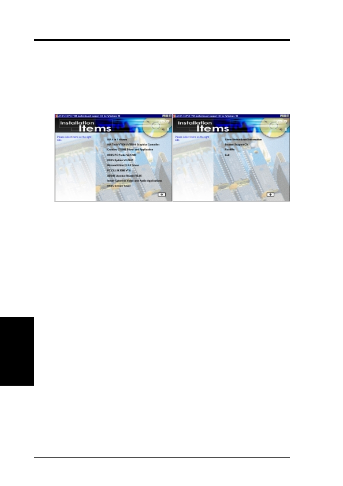
5. SOFTWARE SETUP
5.3 CUPLE-VM Series Support CD
NOTE: The support CD contents are subject to change at any time without notice.
T o begin using your support CD disc, just insert it into your CD-ROM drive and the
support CD installation menu should appear. If the menu does not appear, doubleclick or run D:\ASSETUP.EXE (assuming that your CD-ROM drive is drive D:).
5.3.1 Installation Menu
• VIA 4 in 1 drivers: Installs Bus Master PCI IDE Driver, AGP VxD Driver, VIA
• VIA Tech VT8361/VT8601 Graphics Controller: Installs support for the
• Creative CT5880 Driver and Application: Drivers and seasy-to-use audio soft-
• ASUS PC Probe Vx.xx: Installs a smart utility to monitor your computer’s fan,
• ASUS Update Vx.xx: Installs ASUS\Update to help you update your BIOS or
•
• PC-Cillin 2000Vx.xx: Installs the PC-Cillin virus protection software. View
5. S/W SETUP
Windows 98
• ADOBE Acrobat Reader Vx.xx: Installs the Adobe Acrobat Reader software neces-
• Install Cyberlink Video and Audio Applications: (optional) Installs Cyberlink
• ASUS Screen Saver: Installs ASUS screen saver on the PC.
• Show Motherboard Information: Allows you to view information about your
• Browse Support CD: Allows you to view the contents of the CD.
• ReadMe: Allows you to view the support CD file list and contact information.
• Exit: Exits the CD installation menu.
Additonal CD Content: Flash BIOS writer in the AFLASH folder
Chipset Functions Registry, and IRQ Routing Miniport Driver.
integrated graphics controller.
ware for the Creative audio chip.
temperature, and voltages.
download BIOS image file from the Internet.
Microsoft DirectX Driver: Installs Microsoft DirectX driver.
the online help for more information.
sary to view user’s manuals saved in PDF format. Updated or other language versions of
this motherboard's manual is available in PDF format at any of our web sites.
PowerPlayer SE, PowerDVD Trial, and Cyberlink VideoLive Mail.
(To see the next menu, click on the right arrow in the lower-right corner)
motherboard, such as product name, BIOS version, and CPU.
(To see the previous menu, click on the left arrow in the lower-right corner)
74
ASUS CUPLE-VM User’s Manual
Page 75
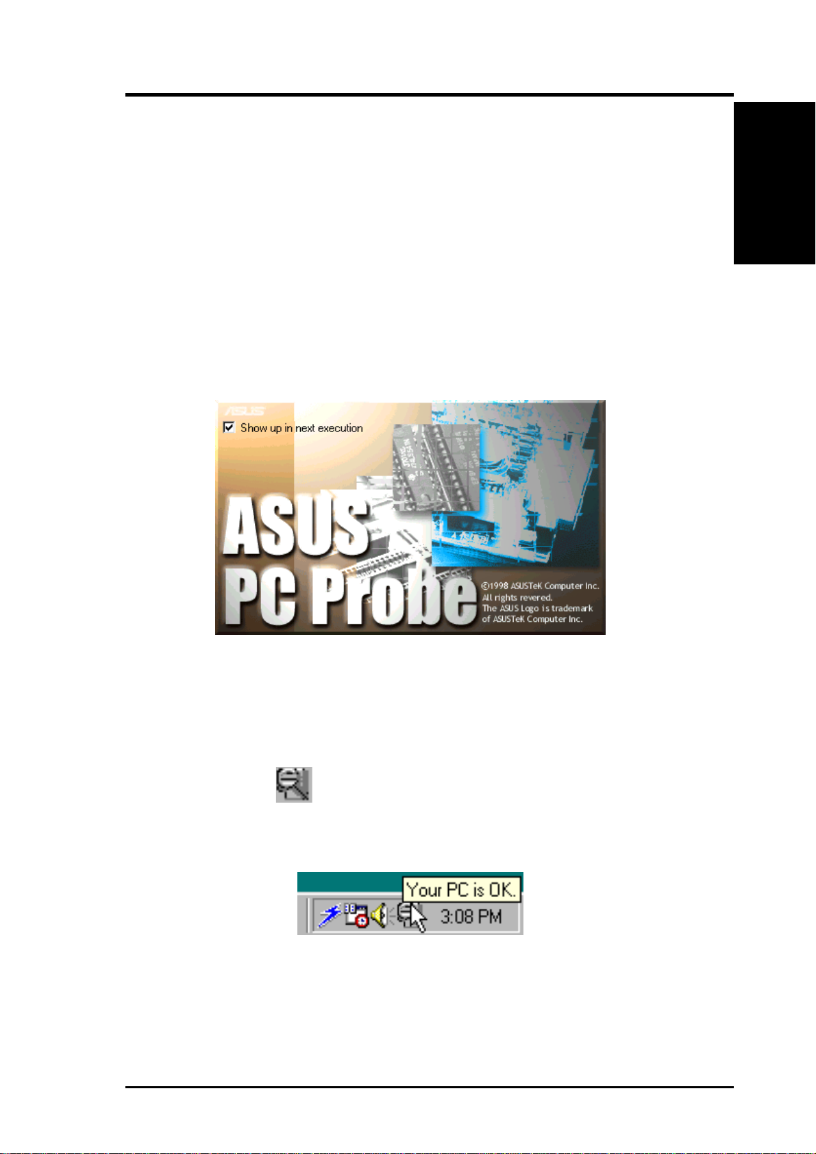
6. SOFTWARE REFERENCE
6.1 ASUS PC Probe
ASUS PC Probe is a convenient utility to continuously monitor your computer system’s vital components, such as fan rotations, voltages, and tem-
peratures. It also has a utility that lets you review useful information about
your computer, such as hard disk space, memory usage, and CPU type, CPU
speed, and internal/external frequencies through the DMI Explorer.
6.1.1 Starting ASUS PC Probe
When ASUS PC Probe starts, a splash screen appears allowing you to select
whether to show the screen again when you open PC Probe or not. To bypass this startup screen, clear the Show up in next execution check box.
ASUS PC Probe
6. S/W REFERENCE
To open ASUS PC Probe, click the Windows Start button, point to Programs, and then ASUS Utility, and then click Probe Vx.xx.
The PC Probe icon
that ASUS PC Probe is running. Clicking the icon will allow you to see the
status of your PC.
will appear on the taskbar’s system tray indicating
ASUS CUPLE-VM User’s Manual 75
Page 76
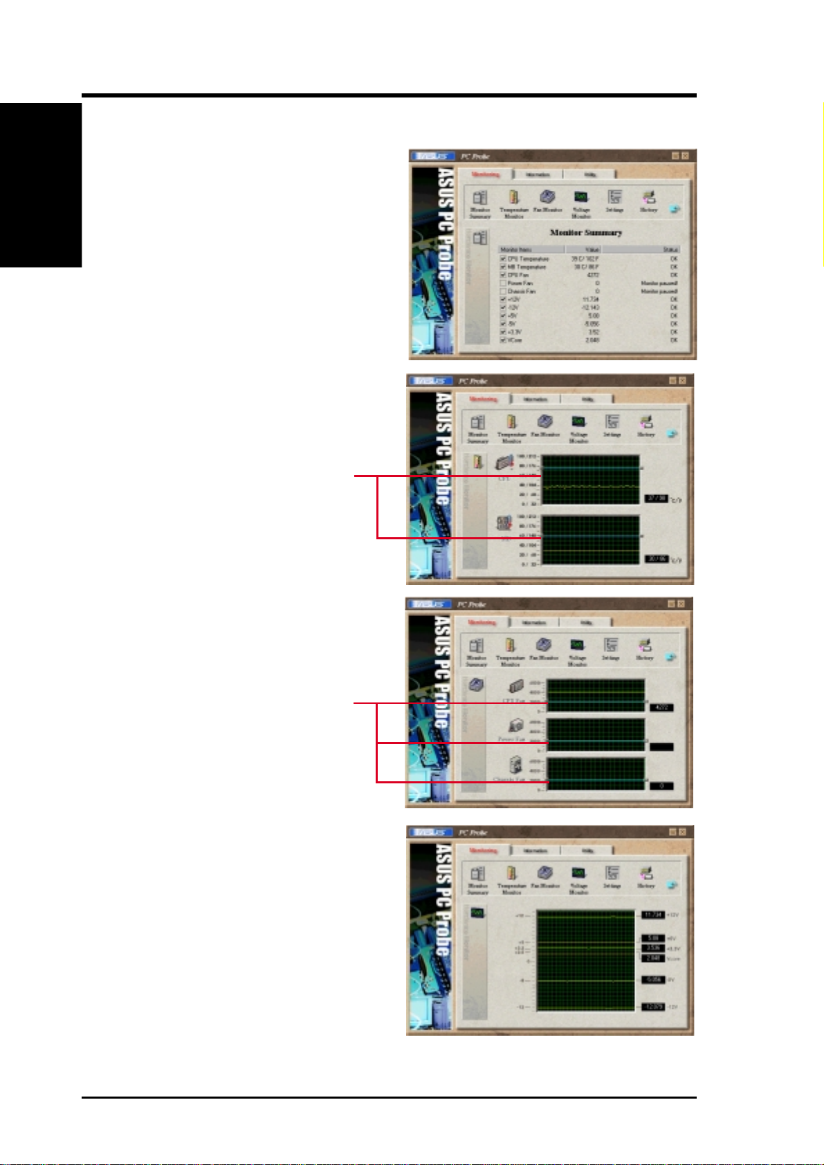
6. SOFTWARE REFERENCE
6. S/W REFERENCE
ASUS PC Probe
6.1.2 Using ASUS PC Probe
Monitoring
Monitor Summary
Shows a summary of the items being
monitored.
Temperature Monitor
Shows the PC’s temperature (for
supported processors only).
(Move the slider up to increase the
threshold level or down to decrease
Temperature Warning
threshold adjustment
the threshold level)
Fan Monitor
Shows the PC’s fan rotation.
Fan Warning
threshold adjustment
(Move the slider up to increase the
threshold level or down to decrease
the threshold level)
Voltage Monitor
Shows the PC’s voltages.
ASUS CUPLE-VM User’s Manual76
Page 77
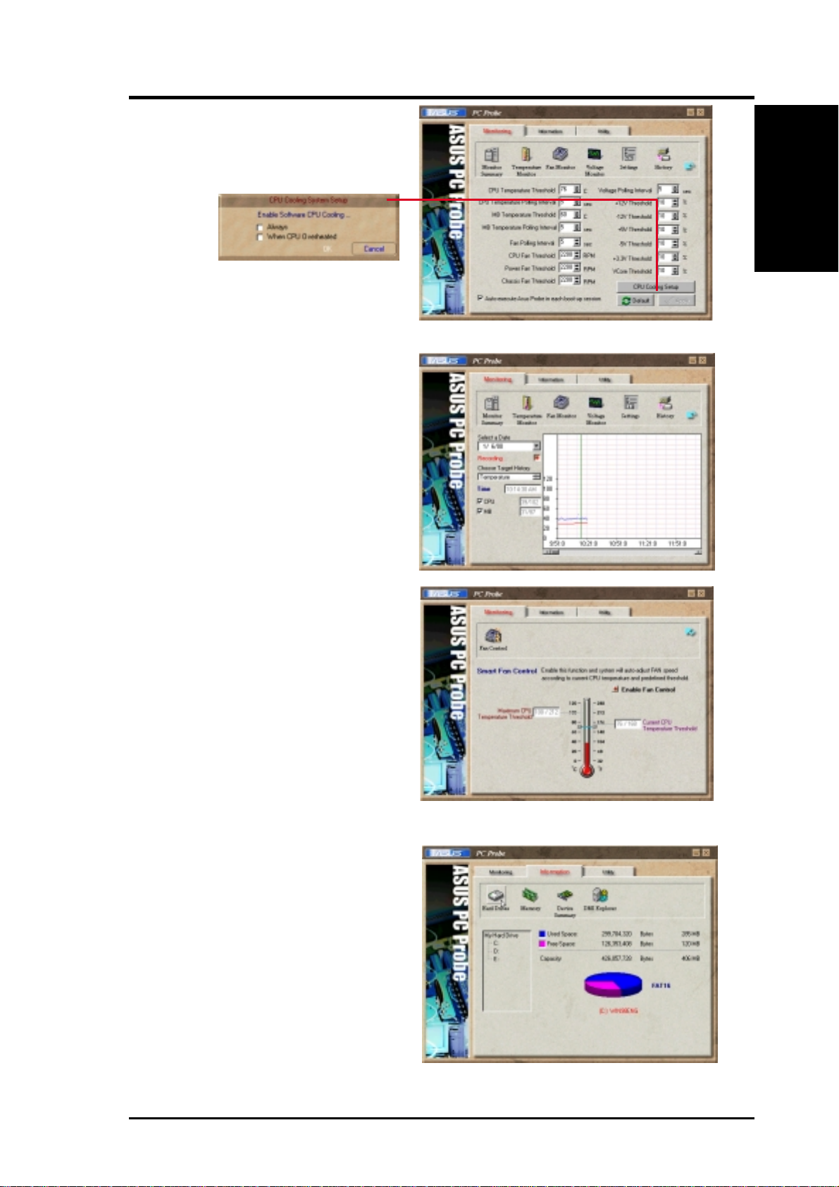
6. SOFTWARE REFERENCE
Settings
Lets you set threshold levels and polling intervals or refresh times of the PC’s
temperature, fan rotation, and voltages.
CPU Cooling System Setup
Lets you select when to enable software CPU
cooling. When When CPU Overheated is selected,
the CPU cooling system is enabled whenever the
CPU temperature reaches the threshold value.
History
Lets you record the monitoring activity of a certain component of your PC
for future reference.
ASUS PC Probe
6. S/W REFERENCE
Fan Control
Lets you enable/disable Smart Fan
Control. Smart Fan Control adjusts the
fan speed automatically based on the
current CPU temperature and predefined threshold.
NOTE: This feature is not available on
ASUS Probe version 2.12.01/2.12.02
Information
Hard Drives
Shows the used and free space of the
PC’s hard disk drives and the file allo-
cation table or file system used.
ASUS CUPLE-VM User’s Manual 77
Page 78
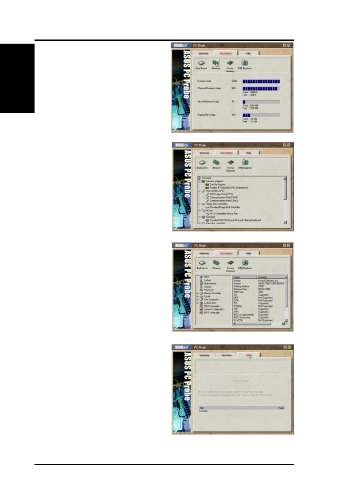
6. SOFTWARE REFERENCE
6. S/W REFERENCE
ASUS PC Probe
Memory
Shows the PC’s memory load, memory
usage, and paging file usage.
Device Summary
Shows a summary of devices in your PC.
DMI Explorer
Shows information pertinent to the PC,
such as CPU type, CPU speed, and internal/external frequencies, and memory
size.
Utility
Lets you run programs outside of the
ASUS Probe modules. T o run a program,
click Execute Program. NOTE: This
feature is currently unavailable.
ASUS CUPLE-VM User’s Manual78
Page 79
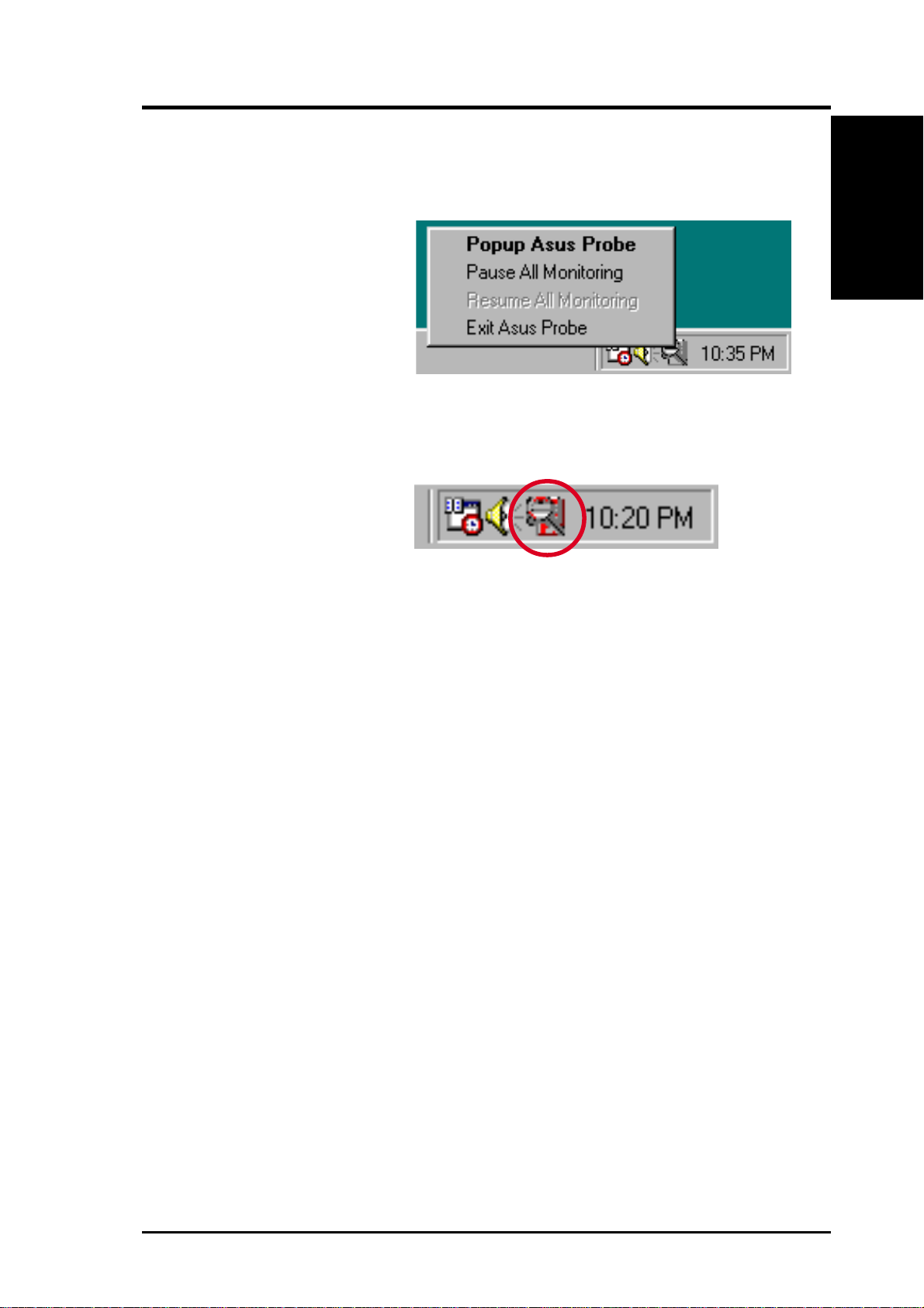
6. SOFTWARE REFERENCE
6.1.3 ASUS PC Probe Task Bar Icon
Right clicking the PC Probe
icon will bring up a menu to
open or exit ASUS PC Probe
and pause or resume all system monitoring.
When the ASUS PC Probe
senses a problem with your
PC, portions of the ASUS PC
Probe icon changes to red, the
PC speaker beeps, and the
ASUS PC Probe monitor is displayed.
ASUS PC Probe
6. S/W REFERENCE
ASUS CUPLE-VM User’s Manual 79
Page 80
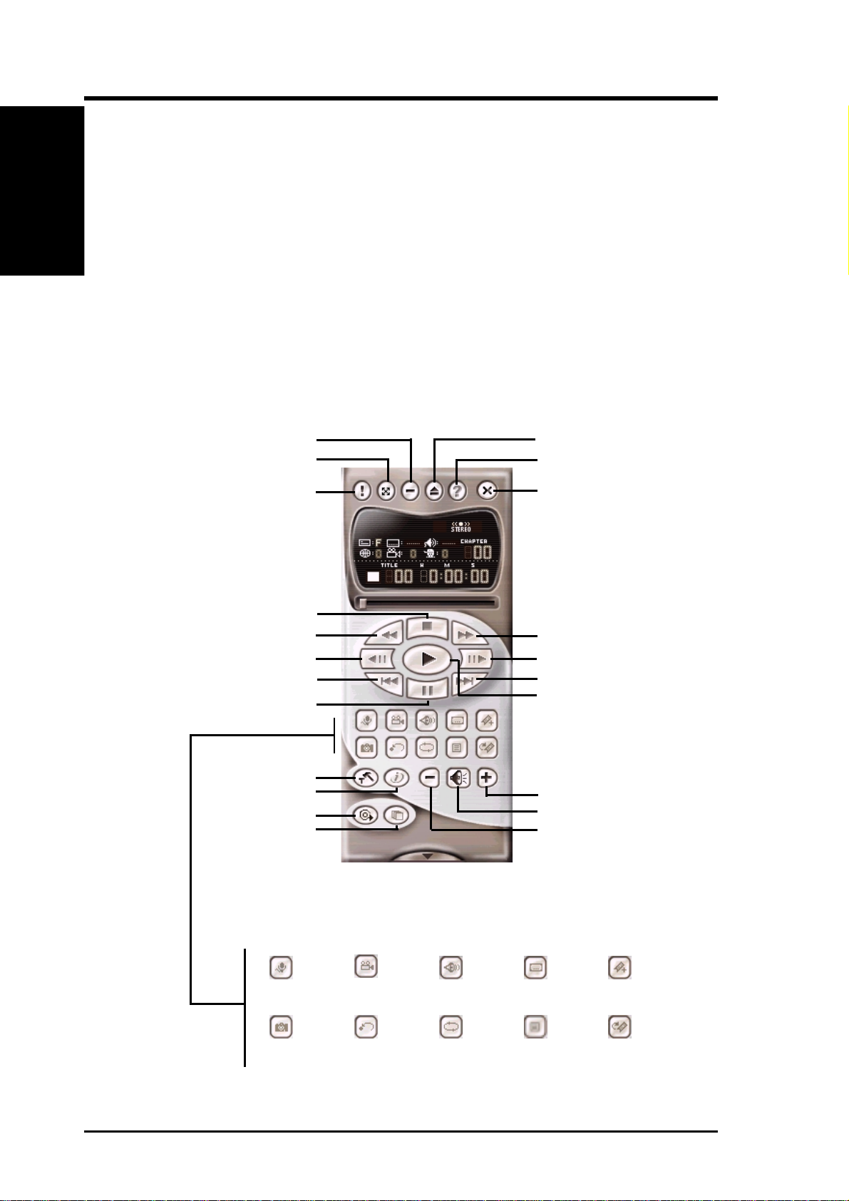
6. SOFTWARE REFERENCE
6. S/W REFERENCE
6.2 CyberLink PowerPlayer SE
PowerPlayer
CyberLink PowerPlayer SE is an intelligent software player that can automatically
detect and playback all kinds of video/audio files, CD and MP3 files as well. This is
the only software you need for all types of video and audio files. No need to waste
time identifying your file types.
6.2.1 Starting CyberLink PowerPlayer SE
To start CyberLink Power Player, click the Windows Start button, point
to Programs, and then CyberLink PowerPlayer SE, and then click
PowerPlayer.
6.2.2 CyberLink PowerPlayer Control Panel
Minimize
Zoom
About
Eject
Help
Power Off
Stop
Backward Scan
Backstep Frame
Previous
Stop
Configuration
i-Power!
CD Mode
Shuffle
Karaoke Next angle Next audio stream Next subtitle Add bookmark
Forward Scan
Step Frame
Next
Play
Increase Volume
Mute
Decrease Volume
Capture frame Go-Up Repeat Menu Go to bookmark
ASUS CUPLE-VM User’s Manual80
Page 81
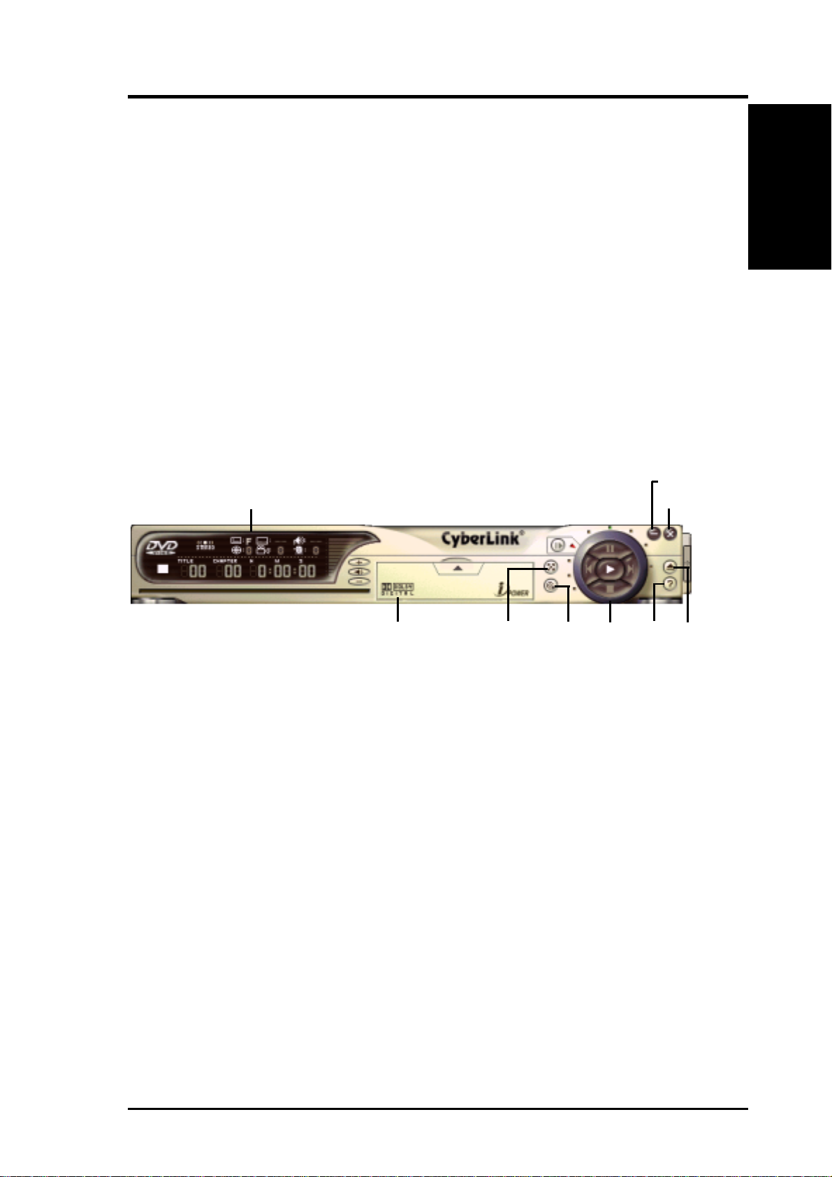
6. SOFTWARE REFERENCE
6.3 CyberLink PowerDVD
CyberLink PowerDVD is the flagship of CyberLink’s complete range of video and
audio software products. It features unrivaled functions allowing users to view high
quality video and media-rich DVD contents on the personal computer. With the iPower Internet Enabling feature, PowerDVD opens DVD enthusiasts to on-line DVD
resources via the PowerDVD Desktop Portal Page.
6.3.1 Starting CyberLink PowerDVD
To start CyberLink PowerDVD, click the Windows Start button, point to
Programs, and then CyberLink PowerDVD, and then click PowerDVD.
6.3.2 CyberLink PowerDVD User Interface
Minimize
Main Display
Exit
PowerDVD
6. S/W REFERENCE
Control
Panel
(closed)
Full Screen /
Video Window
CD/File
Mode
Control
Wheel
Functions
EjectHelp
ASUS CUPLE-VM User’s Manual 81
Page 82

6. SOFTWARE REFERENCE
6. S/W REFERENCE
VideoLive Mail
6.4 CyberLink VideoLive Mail
CyberLink’s V ideoLive Mail Plus Ver 3.0 (a.k.a. VLM 3) is a convenient and excel-
lent way to create professional quality video mails from PC video/audio input devices and to send the mails to any recipients via VLM 3’s built-in e-mail system
through the Internet. VLM 3’s mails comprise video, sound, or snapshot informa-
tion; and thus may convey the most profound information to target audiences. It is
very convenient for mail recipients who do not need to install additional software
component in order to view VLM 3 mails.
VLM 3 works as a very applicant sales tool. It efficiently delivers profound and live
product information to your target customers without costing a fortune. VLM 3 also
helps corporate managers easily give vivid speeches and broadcast through corporate E-mail system. For personal or home users, VLM 3 easily records live video
clips allowing users to send them to friends or family members across the Internet.
VLM 3 loads video messages from PC cameras, digital camcorders, analog camcorder
via video capture cards, or from an existing AVI video clips, and captures audio
messages from PC microphones. Video and audio messages are encoded at a very
high compressed rate in a real-time mode. From data input, data conversion, to
sending video mails via Internet, or saving data to disks, the whole procedure is
done in an easy and continuous process.
VLM 3’s video clip compression rate is up to 1:900, and its playback rate is up to 30
frame per second. VLM 3 provides CIF (352 x 288 pixel) display resolution, and
support true color configuration. A one-minute video mail with QCIF (176 x 144)
resolution takes up less than 500KB of memory , making it easy to transmit and save
mail. Users may always adjust resolution and recording parameters for different
purpose.
VLM 3 supports all the hardware devices that are compliant with Video for Windows standard. V ideo for W indows is a well-accepted and well-tested standard. Thus,
users do not have to worry about compatibility issues.
ASUS CUPLE-VM User’s Manual82
Page 83
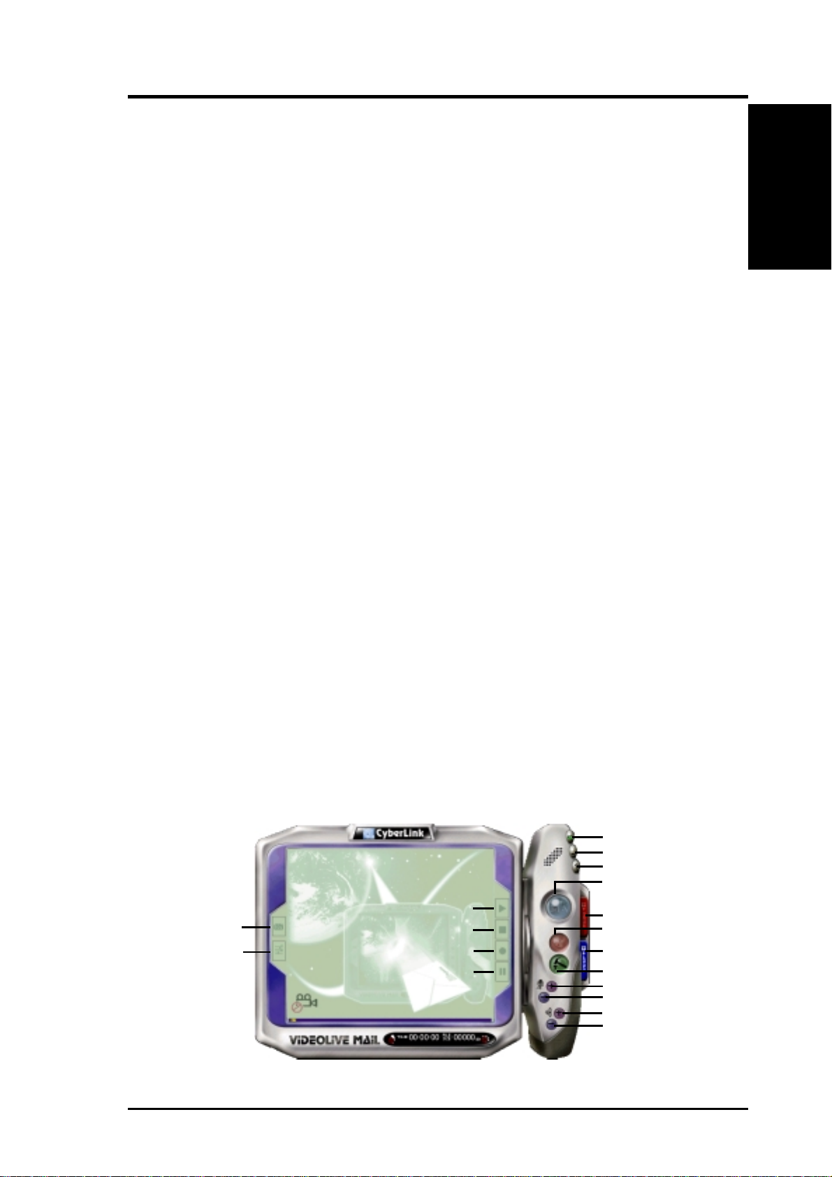
6. SOFTWARE REFERENCE
6.4.1 Starting VideoLive Mail
To start VideoLive Mail, click the Windows Start button, point to Programs, and
then CyberLink VideoLive Mail, and then click VideoLive Mail x.x. VLM 3’s
Setup Wizard will start and guide you through configuring the video and audio input
peripherals and to setup the e-mail environment.
1. Setup Wizard first will prompt a dialog to confirm that you want to configure
the hardware and E-mail setting. Click Yes to continue the system parameter
configuration.
2. The e-mail configuration screen appears. You will need to enter your name and
the e-mail address. Click Next to continue.
3. The Internet e-mail configuration screen appears. You may choose to use the
VLM 3 built-in E-mail functionality (SMTP mail), or use MAPI compliant email system. Consult your ISP or MIS staff for the E-mail server IP address if
you are not sure. Click Next to continue.
4. Then the Video Configuration screen shows up. You may have to specify the
video driver for VLM 3, if there are several video-input devices installed. Then
configure the number of video frames to be captured per second. Note that the
more frames you choose, the bigger the file size will be. Click Next to continue.
VideoLive Mail
6. S/W REFERENCE
5. Then the Setup Wizard will then search for the GSM CODECS module for audio compression, and prompt you with the result. Click Next to continue.
6. Setup Wizard then tests the audio volume during playing and recording. Click
Next when ready.
7. Configuration done. Click Finish to complete the environmental setting procedure.
6.4.2 CyberLink VideoLive Mail User Interface
Exit
Minimize
Help
Video Mail Wizard
Snapshot to File
Video Configuration
Start Playback
Stop Recording / Playback
Start Recording
Pause
Save Video File
Send Mail
Load Video File
Send Mail
Increase MIC volume
Decrease MIC volume
Increase speaker volume
Decrease speaker volume
ASUS CUPLE-VM User’s Manual 83
Page 84
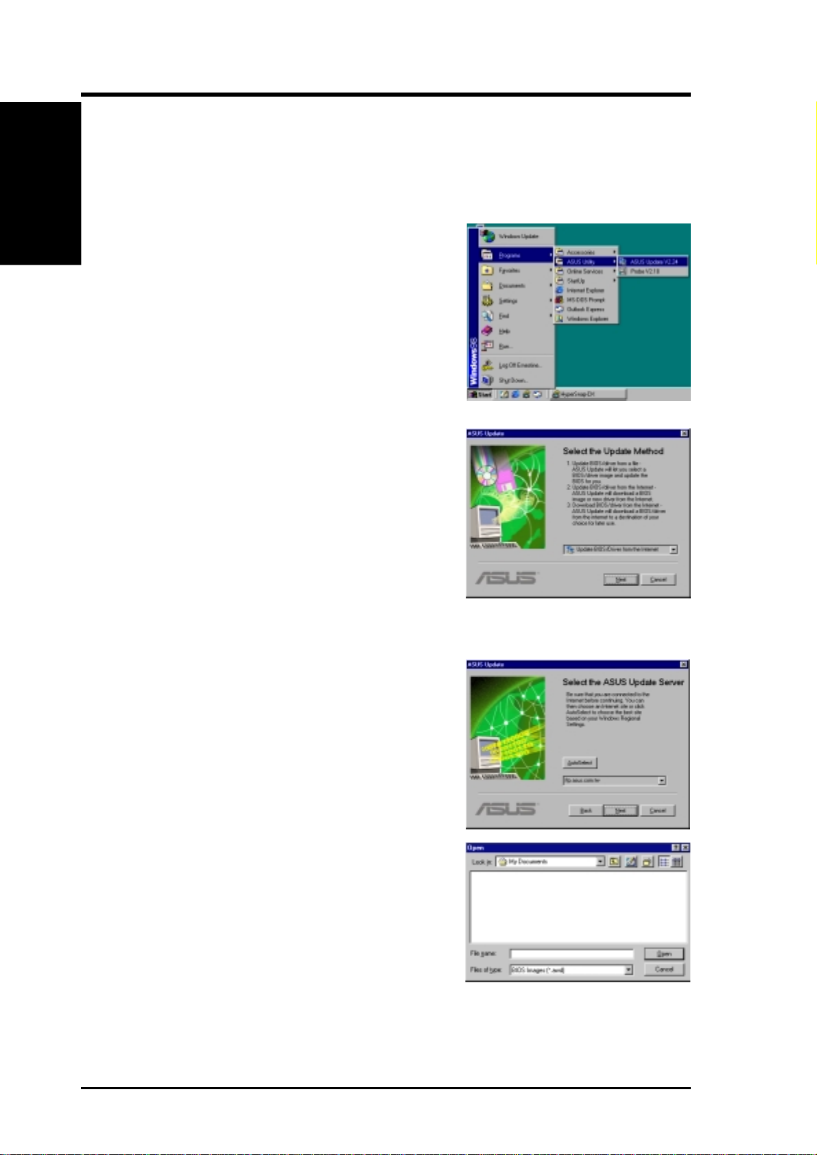
6. SOFTWARE REFERENCE
6. S/W REFERENCE
ASUS Update
6.5 ASUS Update
ASUS LiveUpdate is a utility that allows you to update your motherboard’s
BIOS and drivers. The use of this utility requires that you are properly connected to the Internet through an Internet Service Provider (ISP).
1. Start ASUS Update
Launch the utility from Start | Programs | ASUS
Utility | ASUS Update Vx.xx.
2. Select an update method.
3. If you selected updating/downloading from the
Internet, you will need to select an Internet site.
Choose the site that is closest to you or click
Auto Select.
If you selected Update from a file, you will
be prompted to locate the file.
ASUS CUPLE-VM User’s Manual84
Page 85

7. APPENDIX
7.1 Glossary
1394
1394 is the IEEE designation for the high performance serial bus at 12.5, 25 or
50MBytes/sec speeds. This serial bus defines both a back plane physical layer and a
point-to-point cable-connected virtual bus. The primary application of the cable version is the integration of I/O connectivity at the back panel of personal computers
using a low-cost, scalable, high-speed serial interface. The 1394 standard also provides new services such as live connect/disconnect capability for external devices
including disk drives, printers and hand-held peripherals such as scanners and cameras. This is a new standard to complement the slower USB interface and to compete
with the more expensive SCSI interface.
AC97 (Audio Codec '97)
AC '97 is the next step in enabling PCs with audio quality comparable to consumer
electronics devices. The specification defines new cost-effective options to help integrate the components necessary to support next-generation auto-intensive PC applications such as DVD, 3-D multiplayer gaming and interactive music. The specification also defines new extensions supporting modem and docking to help both
desktop and mobile manufacturers adopt these new technologies more quickly and
cost-effectively . This specification uses software emulation to compete with the PCI
SoundBlaster specification.
ACPI (Advanced Configuration and Power Interface)
The ACPI specification defines a cross-platform interface designed to support many
operating systems. ACPI defines a flexible and abstract hardware interface that provides a standard way to integrate power management features throughout a PC system, including hardware, operating system and application software. This enables
the system to automatically turn ON and OFF peripherals such as CD-ROMs, network cards, hard disk drives, and printers, as well as consumer devices connected to
the PC such as VCRs, TVs, phones, and stereos. With this technology, peripherals
will also be able to activate the PC. For example, inserting a tape into a VCR can
turn on the PC, which could then activate a large-screen TV and high-fidelity sound
system.
AGP (Accelerated Graphics Port)
An interface specification that enables high-performance 3D graphics on mainstream
PCs. AGP was designed to offer the necessary bandwidth and latency to perform
texture mapping directly from system memory.
Glossary
7 . APPENDIX
Bus Bus Frequency Bandwidth Data Transfer Rate
PCI 33MHz 33MHz 133MByte/sec
AGP 1X 66MHz 66MHz 266MByte/sec
AGP 2X 66MHz 133MHz 512MByte/sec
AGP 4X 66MHz 266MHz 1024MByte/sec
BIOS (Basic Input/Output System)
BIOS is a set of routines that affect how the computer transfers data between computer components, such as memory, disks, and the display adapter. The BIOS instructions are built into the computer’s read-only memory. BIOS parameters can be
configured by the user through the BIOS Setup program. The BIOS can be updated
using the provided utility to copy a new BIOS file into the EEPROM.
Bit (Binary Digit)
Represents the smallest unit of data used by the computer . A bit can have one of two
values: 0 or 1.
ASUS CUPLE-VM User’s Manual 85
Page 86

7. APPENDIX
Glossary
7. APPENDIX
Boot
Boot means to start the computer operating system by loading it into system memory .
When the manual instructs you to “boot” your system (or computer), it means to
turn ON your computer . “Reboot” means to restart your computer . When using W indows 95 or later, selecting “Restart” from “Start | Shut Down...” will reboot your
computer.
Bus Master IDE
PIO (Programmable I/O) IDE requires that the CPU be involved in IDE access and
waiting for mechanical events. Bus master IDE transfers data to/from the memory
without interrupting the CPU. Bus master IDE driver and bus master IDE hard disk
drives are required to support bus master IDE mode.
Byte (Binary Term)
One byte is a group of eight contiguous bits. A byte is used to represent a single
alphanumeric character, punctuation mark, or other symbol.
COM Port
COM is a logical device name used by to designate the computer serial ports. Pointing devices, modems, and infrared modules can be connected to COM ports. Each
COM port is configured to use a different IRQ and address assignment.
Concurrent PCI
Concurrent PCI maximizes system performance with simultaneous CPU, PCI and
ISA bus activities. It includes multi-transaction timing, enhanced write performance,
a passive release mechanism and support for PCI 2.1 compliant delayed transactions. Concurrent PCI provides increased bandwidth, reduced system latencies, improves video and audio performance, and improves processing of host based applications.
CPU (Central Processing Unit)
The CPU, sometimes called “Processor,” actually functions as the “brain” of the
computer. It interprets and executes program commands and processes data stored
in memory. Currently, there are socket 370 (for Pentium III FC-PGA and CeleronPPGA), socket 7 (for Pentium, AMD, Cyrix, IBM), slot 1 (for Pentium II and III),
slot 2 (for Xeon), and slot A (for AMD) processors.
Device Driver
A device driver is a special set of instructions that allows the computer’s operating
system to communicate with devices such as VGA, audio, printer, or modem.
DOS (Disk Operating System)
DOS is the foundation on which all other programs and software applications operate, including W indows. DOS is responsible for allocating system resources such as
memory, CPU time, disk space, and access to peripheral devices. For this reason,
DOS constitutes the basic interface between you and your computer.
DRAM (Dynamic Random Access Memory)
There are several different types of DRAM such as, EDO DRAM (Extended Data
Output DRAM), SDRAM (Synchronous DRAM), and RDRAM (Rambus DRAM).
Flash ROM
The flash ROM is designed to be a resident program and can be updated by a specific programming method. Normally , the flash ROM is used for system BIOS which
initiates hardware devices and sets up necessary parameters for the OS. Since the
contents of flash ROM can be modified, users are able to update the BIOS by themselves.
IDE (Integrated Drive Electronics)
IDE devices integrate the drive control circuitry directly on the drive itself, eliminating the need for a separate adapter card (in the case for SCSI devices). UltraDMA/
33 IDE devices can achieve up to 33MB/Sec transfer.
ASUS CUPLE-VM User’s Manual86
Page 87

7. APPENDIX
LPT Port (Line Printer Port)
Logical device name reserved by DOS for the computer parallel ports. Each LPT
port is configured to use a different IRQ and address assignment.
MMX
A set of 57 new instructions based on a technique called Single Instruction, Multiple
Data (SIMD), which is built into the new Intel Pentium PP/MT (P55C) and Pentium
II (Klamath) CPU as well as other x86-compatible microprocessors. The MMX instructions are designed to accelerate multimedia and communications applications,
such as 3D video, 3D sound, video conference.
OnNow
The OnNow design initiative is a comprehensive, system-wide approach to system
and device power control. OnNow is a term for PC that is always ON but appears
OFF and responds immediately to user or other requests. The OnNow design initiative involves changes that will occur in the Microsoft Windows operating system,
device drivers, hardware, and applications, and also relies on the changes defined in
the Advanced Configuration and Power Interface (ACPI) specification.
PC100
SDRAM is Intel's goal is to ensure that memory subsystems continue to support
evolving platform requirements and to assure that memory does not become a bottleneck to system performance. It is especially important to ensure that the PC memory
roadmap evolves together with the performance roadmaps for the processors, I/O
and graphics.
PCI Bus (Peripheral Component Interconnect Local Bus)
PCI bus is a specification that defines a 32-bit data bus interface. PCI is a standard
widely used by expansion card manufacturers.
PCI Bus Master
The PCI Bus Master can perform data transfer without local CPU help and furthermore, the CPU can be treated as one of the Bus Masters. PCI 2.1 supports concurrent PCI operation to allow the local CPU and bus master to work simultaneously.
Plug and Play BIOS
The ISA bus architecture requires the allocation of memory and I/O address, DMA
channels and interrupt levels among multiple ISA cards. However, configuration of
ISA cards is typically done with jumpers that change the decode maps for memory
and I/O space and steer the DMA and interrupt signals to different pins on the bus.
Further, system configuration files may need to be updated to reflect these changes.
Users typically resolve sharing conflicts by referring to documentation provided by
each manufacturer. For the average user, this configuration process can be unreliable and frustrating. Plug and play (PnP) BIOS eliminates the ISA add-on card hardware conflict problem. The PnP BIOS uses a memory block to define and remember
each card's configuration, which allows the user to change the card's IRQs and DMA
in BIOS either automatically or manually.
POST (Power On Self Test)
When you turn ON the computer, it will first run through the POST, a series of
software-controlled diagnostic tests. The POST checks system memory, the motherboard circuitry, the display, the keyboard, the diskette drive, and other I/O devices.
PS/2 Port
PS/2 ports are based on IBM Micro Channel Architecture. This type of architecture
transfers data through a 16-bit or 32-bit bus. A PS/2 mouse and/or keyboard may be
used on ATX motherboards.
Glossary
7 . APPENDIX
RDRAM (Rambus DRAM)
Developed by Rambus, Inc., this type of memory can deliver up to 1.6GB of data
per second. RDRAM is the first interface standard that can be directly implemented
on high performance VLSI components such as, CMOS DRAMs, memory control-
lers, and graphics/video ICs.
ASUS CUPLE-VM User’s Manual 87
Page 88

7. APPENDIX
Glossary
7. APPENDIX
ROM (Read Only Memory)
ROM is nonvolatile memory used to store permanent programs (called firmware)
used in certain computer components. Flash ROM (or EEPROM) can be reprogrammed with new programs (or BIOS).
SCSI (Small Computer System Interface)
High speed multi-threaded I/O interface defined by the X3T9.2 committee of the
American National Standards Institute (ANSI) for connecting many peripheral devices. The standard started from 10MBytes/sec to 160MBytes/sec available today.
SDRAM (Synchronous DRAM)
The SDRAM features a fully synchronous operation referenced to a positive edge
clock whereby all operations are synchronized at a clock input which enables the
coexistence of high performance and a simple user interface. SDRAM takes memory
access away from the CPU's control; internal registers in the chips accept the request, and let the CPU do something else while the data requested is assembled for
the next time the CPU talks to the memory. As they work on their own clock cycle,
the rest of the system can be clocked faster. There is a version optimized for video
cards, and main memory for motherboards.
SPD for SDRAM module
Serial Presence Detect (SPD) is most like an ID detect for SDRAM module, it using
a EEPROM component on DIMM module for storing module configuration information inside. The Serial Presence Detect function is implemented using a 2048 bit
EEPROM component. This nonvolatile storage device contains data programmed
by the DIMM manufacturer that identifies the module type and various SDRAM
organization and timing parameters.
SSE (Streaming SIMD Extensions)
A set of new instructions added to existing architectures that enables a better visual
experience with an accelerated 3D geometry pipeline and support for new applications, such as real-time video encoding and speech recognition.
System Disk
A system disk contains the core file of an operating system and is used to boot up the
operating system.
UltraDMA
Ultra DMA/33 is a "synchronous DMA" protocol designed by Intel. This function is
included into Intel's PIIX4 chipset. The traditional IDE transfer only uses one edge
of the data stroke as the data transfer. Ultra DMA/33 uses both edges of data strobe
when the data is transferred. Hence, the data transfer rate is double of the PIO mode
4 or DMA mode 2 (16.6MB/s x2 = 33MB/s) on ATA-2 devices.
Ultra ATA/66, also known as Ultra DMA/66, is an extension of current Ultra ATA/
33 interface. This new high-speed interface has doubled the Ultra AT A/33 burst data
transfer rate to 66.6 Mbytes/sec and maximized disk performance under current PCI
local bus environment
USB (Universal Serial Bus)
A 4-pin serial cable bus that allows up to 127 plug and play computer peripherals
such as keyboard, mouse, joystick, scanner, printer, modem, and monitor to share a
bandwidth through a host scheduled token based protocol. This allows attaching or
detaching while the host and other peripherals are in operation. Supports synchronous and asynchronous transfer types over the same set of wires up to 12Mbit/sec.
USB 2.0 provides twice the transfer rate compared to USB 1.0 and competes with
the 1394 standard.
Wake-On-LAN
Computer will automatically wake-up upon receiving a wake-up packet through a
Network interface when it is under power soft-off, suspend or sleep mode.
ASUS CUPLE-VM User’s Manual88
Page 89

INDEX
INDEX
A
AC PWR Loss Restart 65
Accelerated Graphics Port
AGP Pro Slot 24
ASUS PC Probe
Using 75
ASUS Update
Using 84
ATAPI CD-ROM 68
ATX Power Supply Connector 33
Audio CODEC Setting 17
Audio Controller 56
Audio Port Connectors 27
B
BIOS
Beep Code 35
BIOS Beep Codes 35
Boot Sequence 68
Boot Up Floppy Seek 69
Boot Up NumLock Status 47
Boot Virus Detection 69
C
C-Media Audio Demo 86
Central Processing Unit (CPU) 20
Installation 21
ZIF Socket 20
Chassis Fan Speed 67
CHS Capacity 46
Connectors
ATX Power Supply 33
Audio Port 27
Floppy Disk Drive 29
IDE 28
Infrared Module 29
Internal Audio 32
Joystick 27
Keyboard 25
MIDI 27
Monitor Output 26
Parallel Port 27
PS/2 Keyboard 25
PS/2 Mouse 25
Serial Port 26
USB 26, 32
Wake-On-LAN 31
Wake-On-Ring 30
CPU. See Central Processing Unit
CPU Fan Speed 67
CPU Temperature 67
Creative Audio
Using 85
CyberLink
PowerDVD 80
PowerPlayer SE 80
VideoLive Mail 82
CyberLink PowerDVD
Using 80
CyberLink PowerPlayer SE
Using 80
CyberLink V ideoLive Mail
Using 82
Cylinders 45
D
Discard Changes 71
DMA x Used By ISA 60
E
ECP DMA Select 55
Exit Discarding Changes 70
Exit Saving Changes 70
Expansion Cards
Assigning IRQs 23
Installing 22
F
Floppy 3 Mode Support 43
Floppy Disk Access Control 54
Floppy Disk Drive Connector 29
ASUS CUPLE-VM User’s Manual 89
Page 90

INDEX
H
Halt On 48
Hardware Setup
Memory Installation 19
HDD Power Down 64
Head 46
Headers
USB 15, 32
I
IDE Activity LED Lead 33
IDE Connectors 28
IDE Hard Drive 68
Infrared Module Connector 29
Installed Memory 48
Internal Audio Connector 32
Interrupt Request (IRQ)
Standard Assignments 23
IRQ XX Used By ISA 59
ISA MEM Block BASE 61
Load Setup Defaults 71
M
Maximum LBA Capacity 46
MB Temperature 67
Memory Installation 19
MIDI Connector 27
Monitor Output Connector 26
Motherboard
IRQ Table 23
Mouse Connector 25
Multi-Sector Transfers 46
O
Onboard AC97 Modem Controlle 56
Onboard CIR IRQ 57
Onboard Parallel Port 55
Onboard Serial Port 1 54
Onboard Serial Port 2 54
OS/2 Onboard Memory > 64M 50
J
Joystick Connector 27
K
Keyboard Connector 25
L
LAN
Jumper Setting 17
Language 48
Leads
IDE Activity LED 33
Legacy Diskette A 43
Legacy Diskette B 43
P
Parallel Port Connector 27
Parallel Port Mode 55
PCI Latency Timer 58
PCI/VGA Palette Snoop 58
PIO Mode 46
Plug & Play O/S 69
Power Fan Speed 67
Power Management 63
PowerDVD 80
Using 80
PowerPlayer SE
Using 80
Procedures
Updating BIOS 38
PS/2 Keyboard Connector 25
PS/2 Mouse Connector 25
PWR Up On Modem Act 65
90 CUPLE-VM User’s Manual
Page 91

INDEX
Q
Quick Power On Self Test 69
R
Removable Device 68
S
Save Changes 71
SDRAM CAS Latency 51
SDRAM RAS Precharge Time 51
Sector 46
Serial Port Connectors 26
Settings 17
Audio CODEC 17
USB Device Wake-up 17
SMART Monitoring 46
SoundBlaster Mixer 85
Using 85
Starting Up 35
Supervisor Password 48
Using
ASUS PC Probe 75
ASUS Update 84
PowerPlayer SE 80
Creative Audio 85
V
VCORE Voltage 67
Video Off Method 64
Video Off Option 64
Video ROM BIOS Shadow 62
VideoLive Mail 82
Using 82
Voltage
+12 67
+3.3 67
+5 67
-12 67
-5 67
VCORE 67
W
Suspend Mode 64
Suspend-to-RAM Capability 64
SYMBIOS SCSI BIOS 58
System Date 43
System Time 43
T
Translation Method 45
Type 44
U
UART2 Use Standard Infrared 54
Ultra DMA Mode 46
Updating Your BIOS 37
USB Device Wake-up Setting 17
USB Function 59
USB Headers 15, 32
Wake On LAN 65
Wake-On-LAN Connector 31
Wake-On-Ring Connector 30
Z
ZIF Socket 20
USB Ports 26
ASUS CUPLE-VM User’s Manual 91
Page 92

NOTES
92 CUPLE-VM User’s Manual
 Loading...