

Page 1
Doc. No:
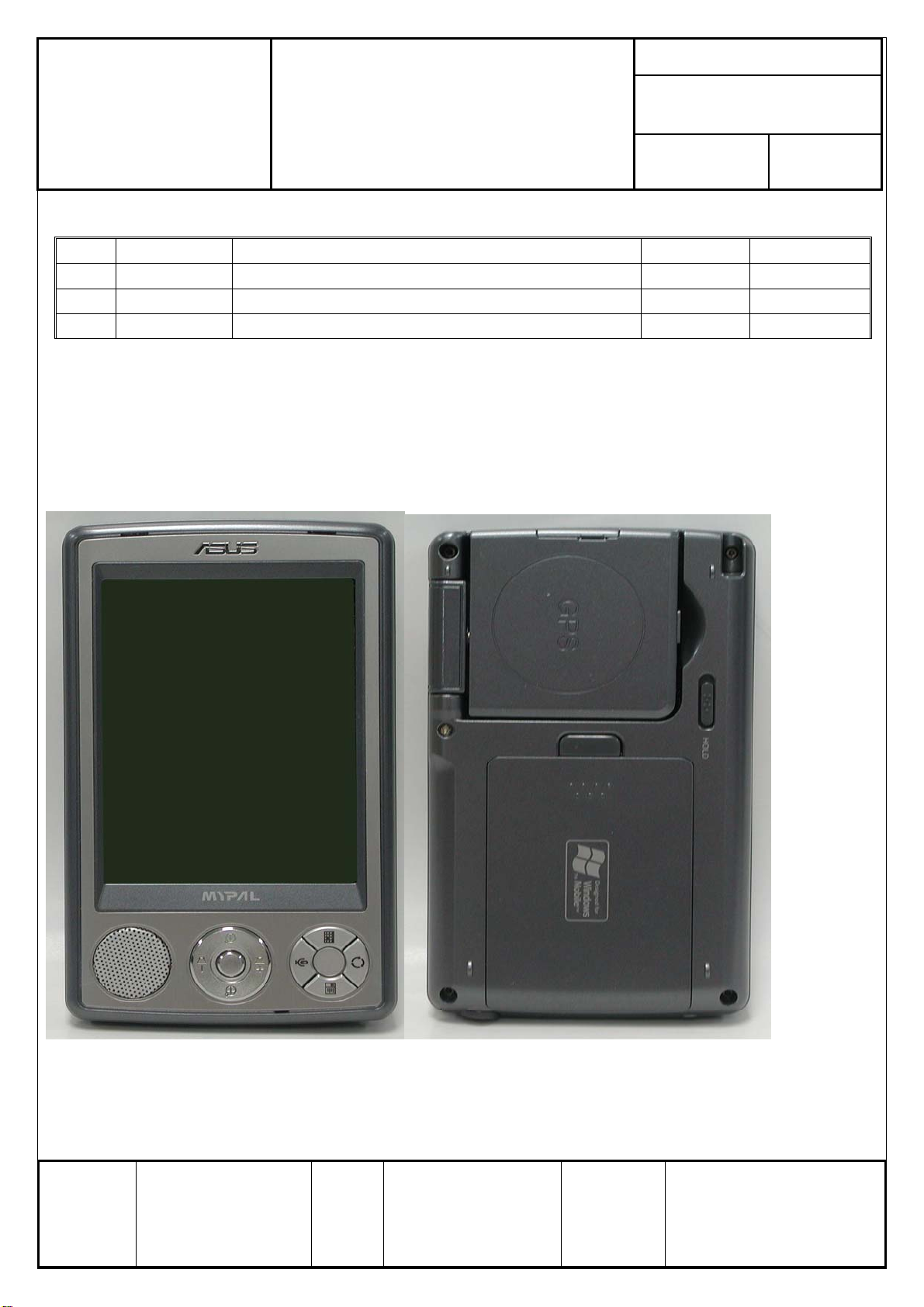
ASUSTeK COMPUTER A63x Assembly & Disassembly
INC.
Guide
Date:
Revision:
Page: Grade:
Rev. Modification Modify description Issue div. Originator
V101 English 1 X #1 Phillips-head Screwdriver Jonathan
V101 English 1 X T-5 Torx Screwdriver
V101 English 1 X Plastic Knife
Purpose:
This SOP is separated into three parts:(1)Overview(2) Disassembly(3) Assembly。
This purpose of this SOP is to help engineer assemble & disassemble more easily。
1. Overview
2. Disassembly
1. Remove SD card (PIC1.1, PIC1.2)
Authorize
by
Review
by
Originator
by
Form No : D2-001-11 Rev.01
Jonathan
Page 2

Doc. No:
ASUSTeK COMPUTER INC.
PIC1.1 PIC1.2
2. Remove the battery cover by pressing the release button and pull back. (PIC2.1)
A63x Assembly & Disassembly
Guide
Date:
Rev.: Page:
1
PIC2.1
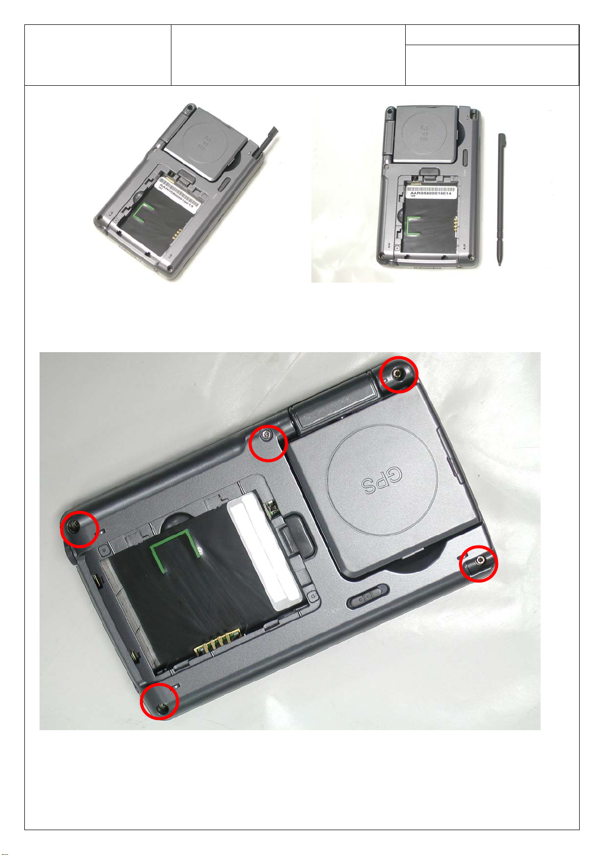
3. Remove the battery. (PIC3.1, PIC3.2)
PIC3.1 PIC3.2
4. Remove Stylus. (PIC4.1, PIC 4.2)
Page 3
Doc. No:
ASUSTeK COMPUTER INC.
PIC4.1 PIC4.2
5. Remove 5 screws (PIC5.1)
A63x Assembly & Disassembly
Guide
Date:
Rev.: Page:
2
PIC5.1
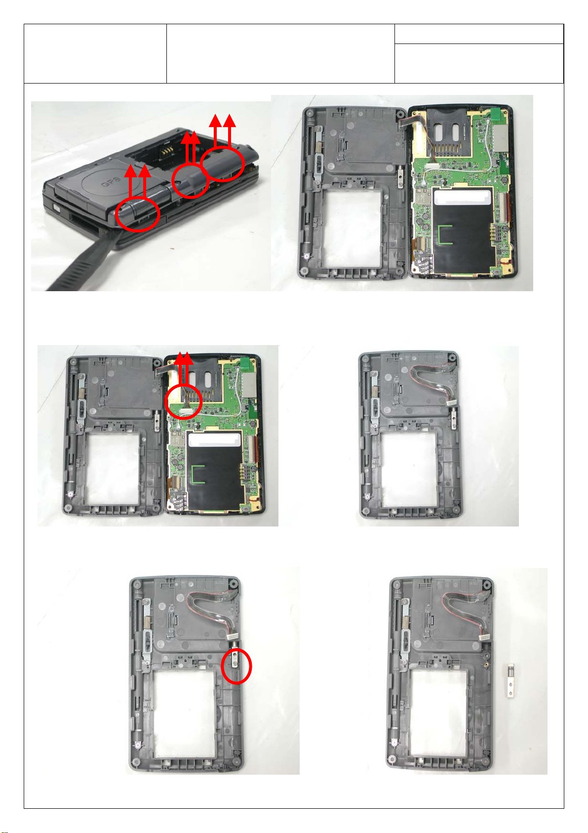
6. Separate the retaining hook with plastic knife. (PIC6.1, PIC6.2)
Page 4
Doc. No:
ASUSTeK COMPUTER INC.
PIC6.1 PIC6.2
7. Slowly pull up connector cable (PIC7.1, PIC7.2)
A63x Assembly & Disassembly
Guide
Date:
Rev.: Page:
3
PIC7.1 PIC7.2
8. Remove 1 screw and hinge (PIC8.1, PIC8.2)
PIC8.1 PIC8.2
Page 5

Doc. No:
ASUSTeK COMPUTER INC.
9. Remove GPS module (PIC9.1, PIC9.2)
PIC9.1 PIC9.2
10. Remove 2 screws and both cover (PIC10.1, PIC10.2, PIC10.3)
A63x Assembly & Disassembly
Guide
Date:
Rev.: Page:
4
PIC10.1 PIC10.2
PIC10.3
Page 6
Doc. No:
ASUSTeK COMPUTER INC.
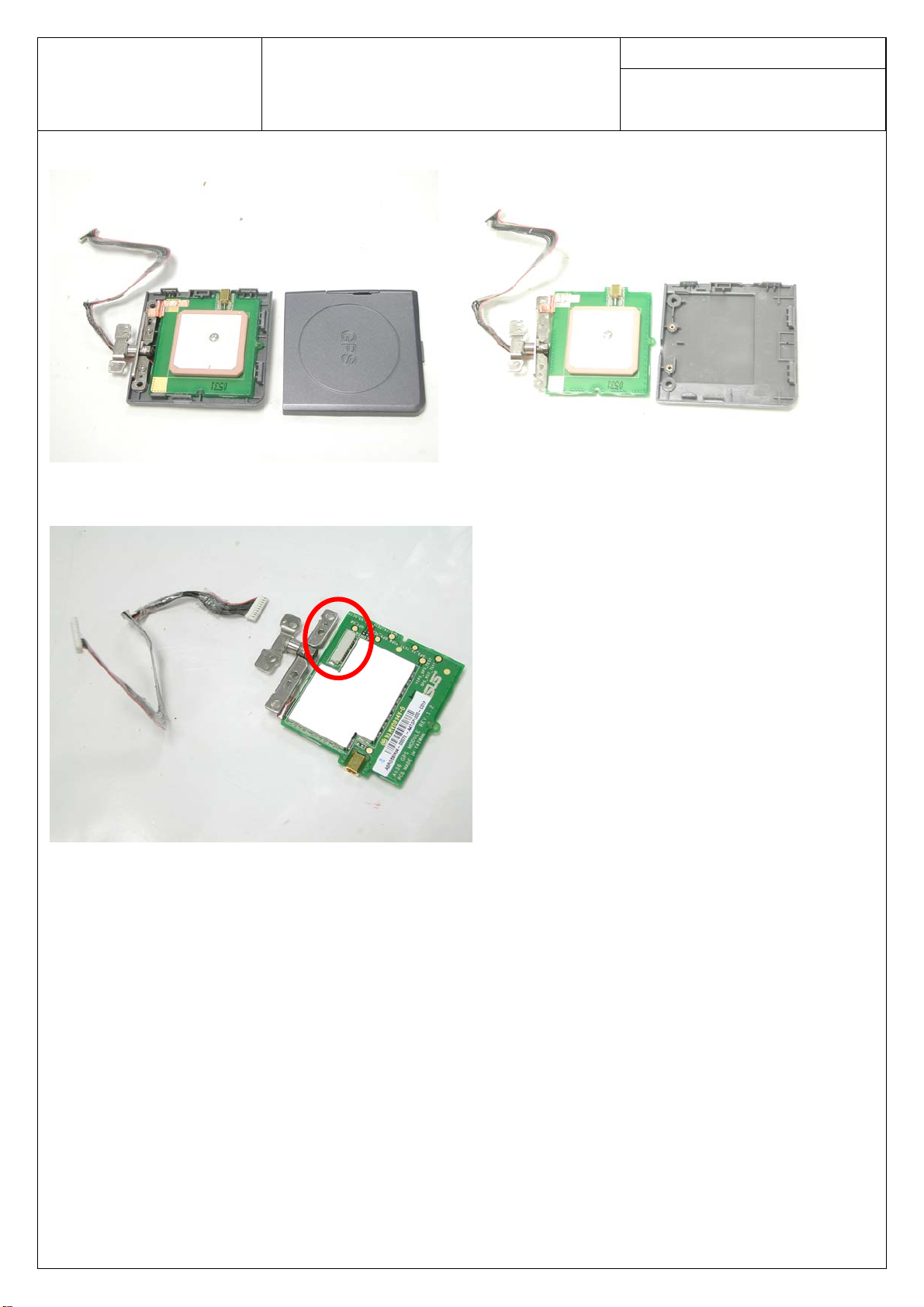
11. Remove top and bottom cover of GPS module. (PIC11.1, PIC11.2)
12. Remove cable here. (PIC12.1)
A63x Assembly & Disassembly
Guide
PIC11.1 PIC11.2
Date:
Rev.: Page:
5
PIC12.1
13. Remove LCD FPC, KEYPAD FPC and Audio connector. (PIC13.1, PIC13.2)
Page 7

Doc. No:
ASUSTeK COMPUTER INC.
A63x Assembly & Disassembly
Guide
Date:
Rev.: Page:
6
PIC13.1
PIC13.2
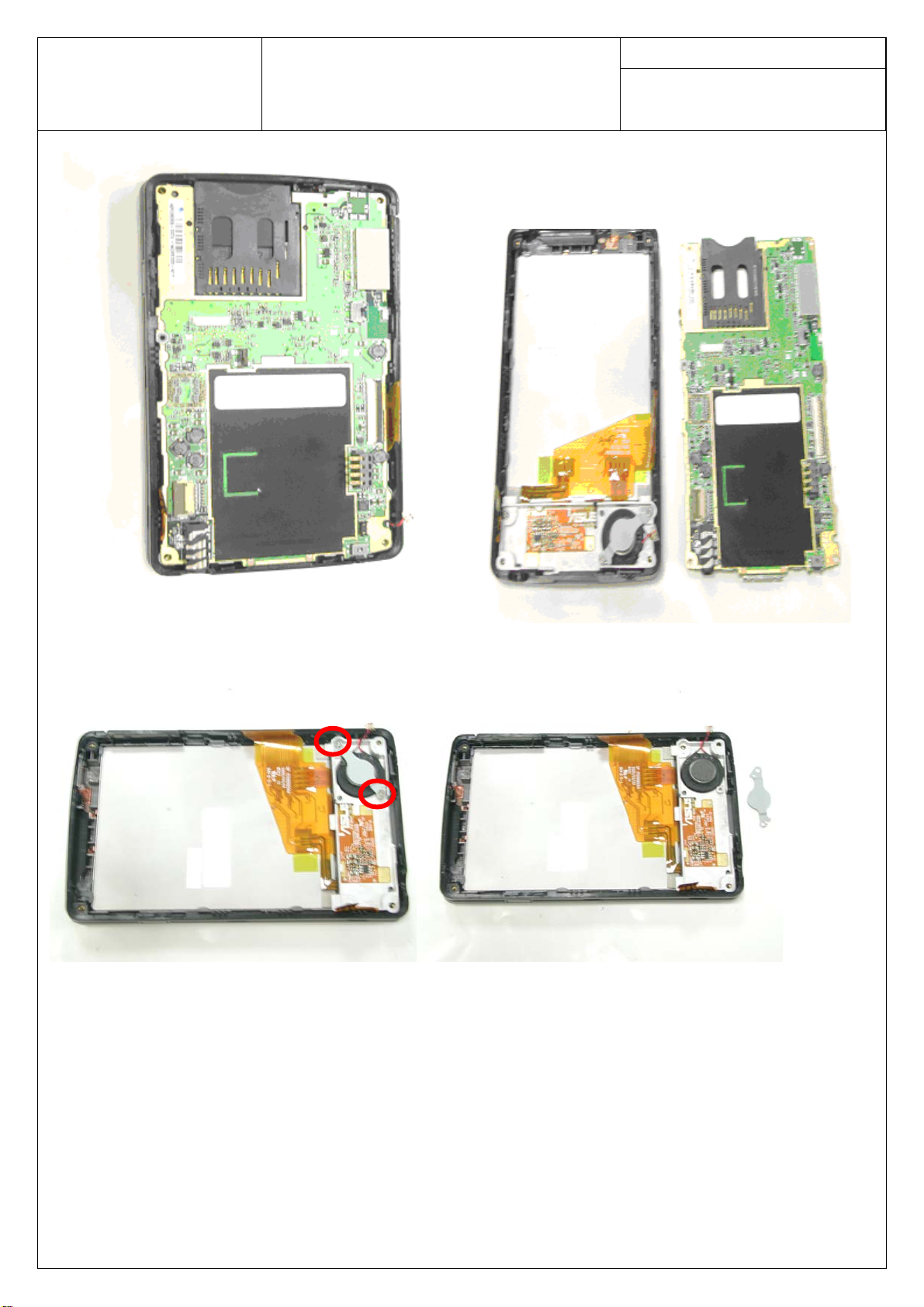
14. Remove the main board module. (PIC14.1, PIC14.2)
Page 8
Doc. No:
ASUSTeK COMPUTER INC.
A63x Assembly & Disassembly
Guide
Date:
Rev.: Page:
7
PIC14.1 PIC14.2
15. Remove 2 screws and speaker holder (PIC15.1, PIC15.2)
PIC15.1 PIC15.2
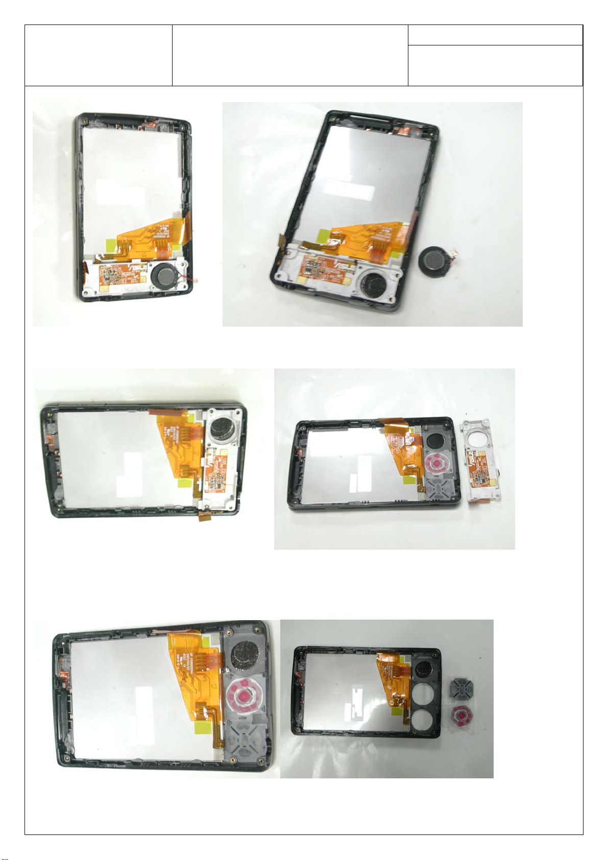
16. Remove Speaker (PIC16.1, PIC16.2)
Page 9
Doc. No:
ASUSTeK COMPUTER INC.
PIC16.1 PIC16.2
17. Remove Keypad module. (PIC17.1, PIC17.2)
A63x Assembly & Disassembly
Guide
Date:
Rev.: Page:
8
PIC17.1 PIC17.2
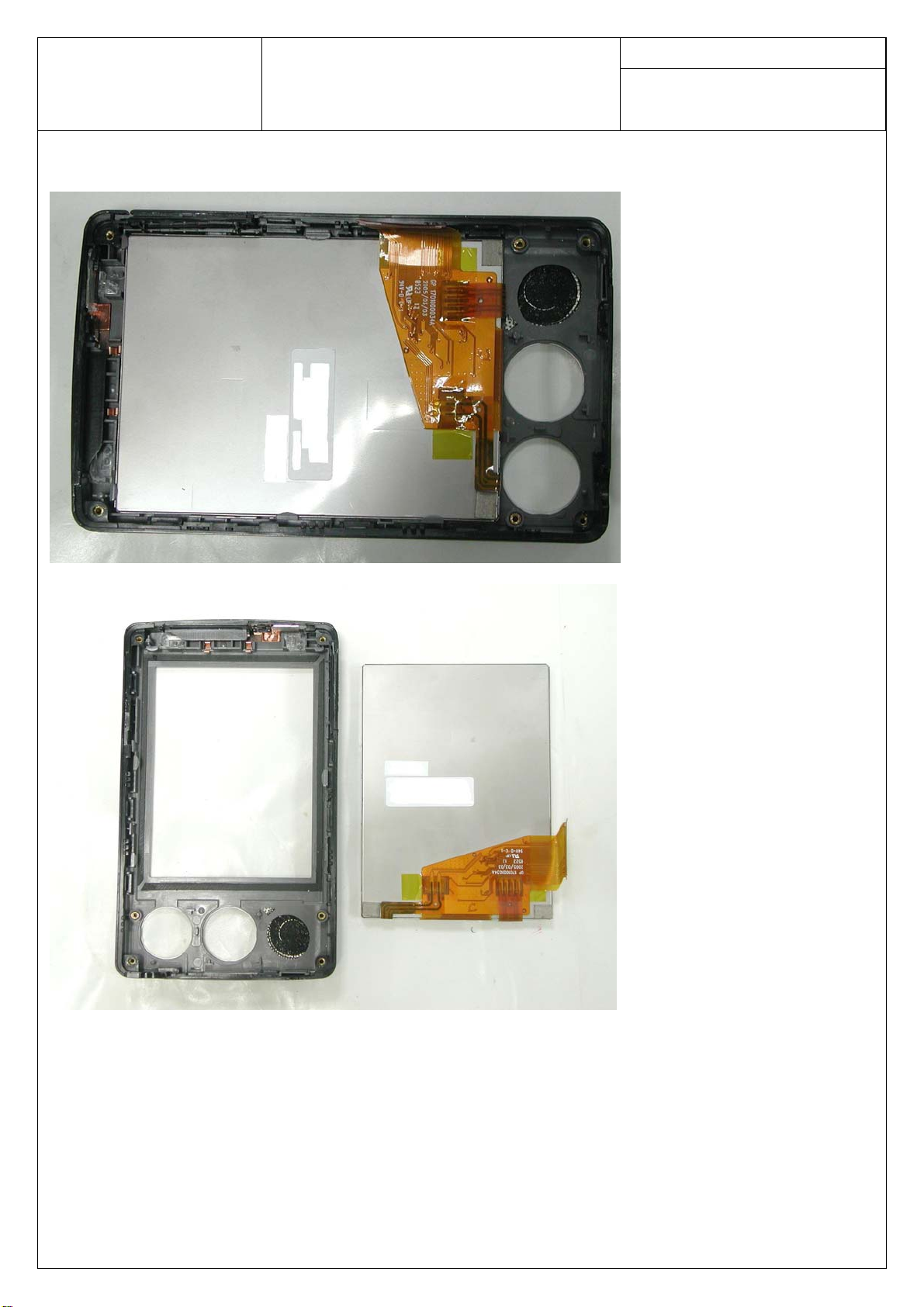
18. Remove Keypad (PIC18.1, PIC18.2)
PIC18.1 PIC18.2
Page 10
Doc. No:
ASUSTeK COMPUTER INC.
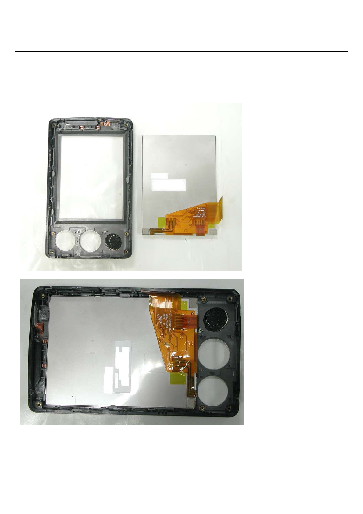
19. Remove LCD (PIC19.1, PIC19.2)
A63x Assembly & Disassembly
Guide
Date:
Rev.: Page:
9
PIC19.1
PIC19.2
Page 11
Doc. No:
ASUSTeK COMPUTER INC.
3. Assembly
1. Assemble LCD (PIC1.1, PIC1.2)
A63x Assembly & Disassembly
Guide
Date:
Rev.: Page:
10
PIC1.1
PIC1.2
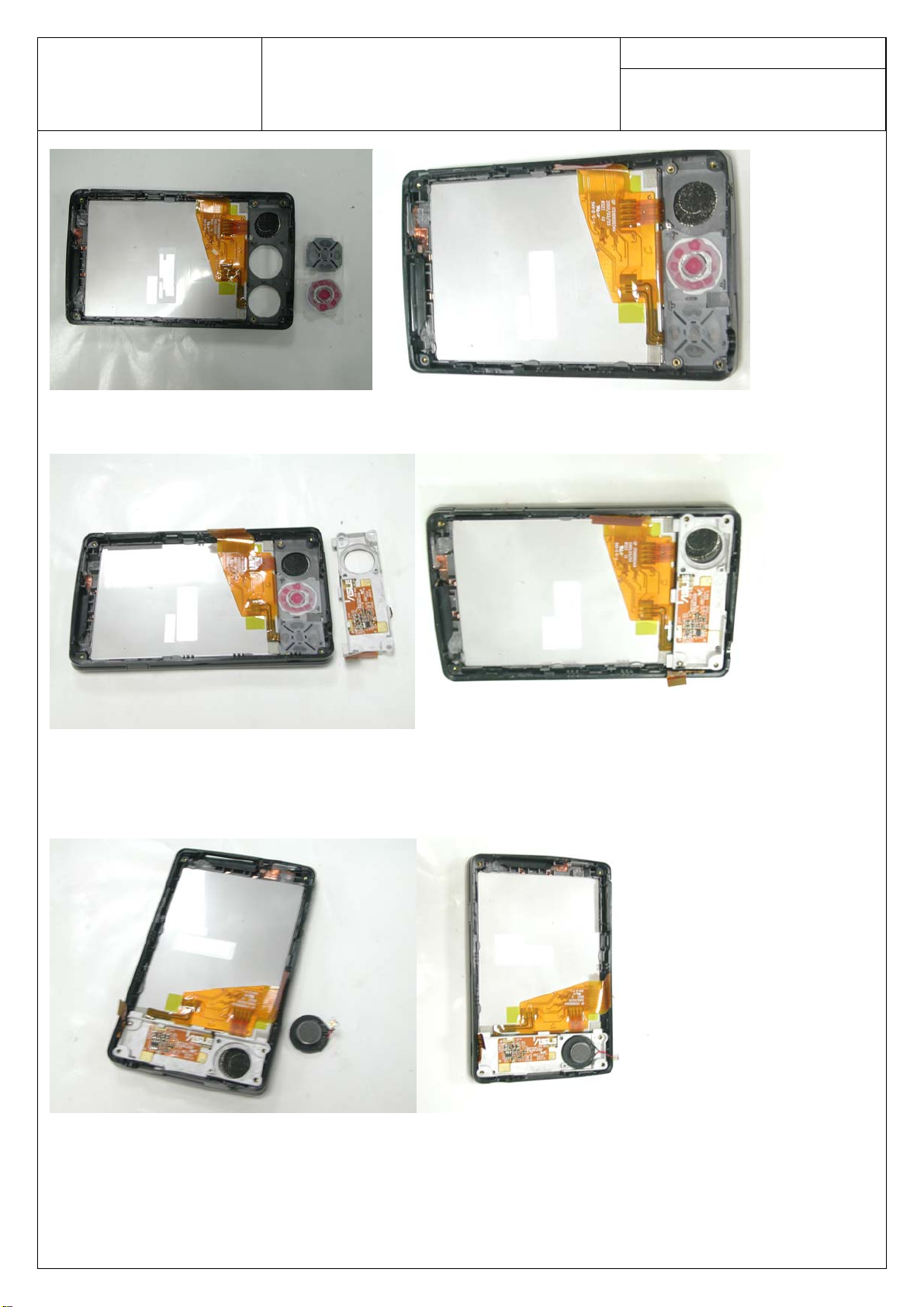
2. Assemble Keypad (PIC2.1, PIC2.2)
Page 12
Doc. No:
ASUSTeK COMPUTER INC.
PIC2.1 PIC2.2
3. Assemble Keypad module. (PIC3.1, PIC3.2)
A63x Assembly & Disassembly
Guide
Date:
Rev.: Page:
11
PIC3.1 PIC3.2
4. Assemble Speaker (PIC4.1, PIC4.2)
PIC4.1 PIC4.2
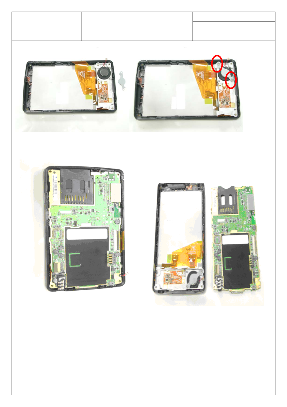
5. Assemble speaker holder and 2 screws (PIC5.1, PIC5.2)
Page 13
Doc. No:
ASUSTeK COMPUTER INC.
PIC5.1 PIC5.2
6. Assemble the main board module. (PIC6.1, PIC6.2)
A63x Assembly & Disassembly
Guide
Date:
Rev.: Page:
12
PIC6.1 PIC6.2
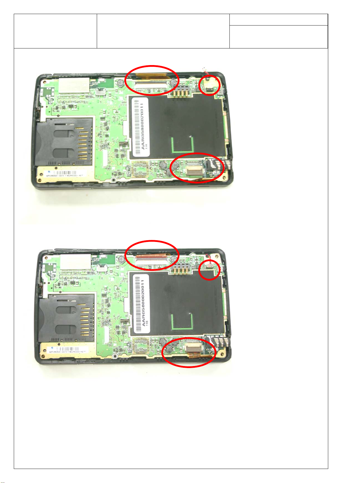
7. Assemble LCD FPC, KEYPAD FPC and Audio connector. (PIC7.1, PIC7.2)
Page 14
Doc. No:
ASUSTeK COMPUTER INC.
A63x Assembly & Disassembly
Guide
Date:
Rev.: Page:
13
PIC7.1
PIC7.2
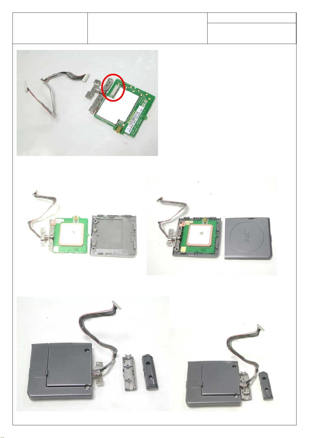
8. Assemble cable here. (PIC8.1)
Page 15
Doc. No:
ASUSTeK COMPUTER INC.
PIC8.1
9. Assemble top and bottom cover of GPS module. (PIC9.1, PIC9.2)
A63x Assembly & Disassembly
Guide
Date:
Rev.: Page:
14
PIC9.1 PIC9.2
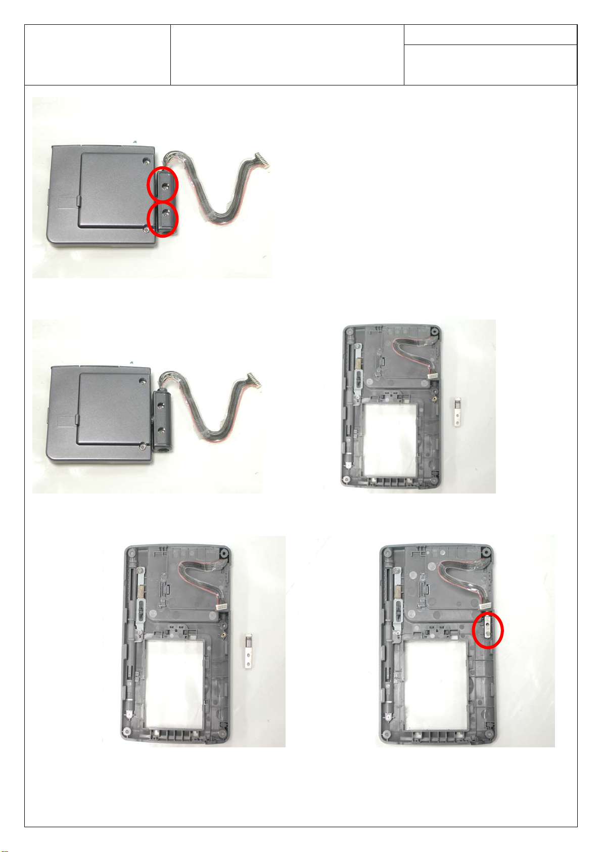
10. Remove 2 screws and both cover (PIC10.1, PIC10.2, PIC10.3)
PIC10.1 PIC10.2
Page 16
Doc. No:
ASUSTeK COMPUTER INC.
PIC10.3
11. Assemble GPS module (PIC11.1, PIC11.2)
A63x Assembly & Disassembly
Guide
Date:
Rev.: Page:
15
PIC11.1 PIC11.2
12. Assemble hinge and screw (PIC12.1, PIC12.2)
PIC12.1 PIC12.2
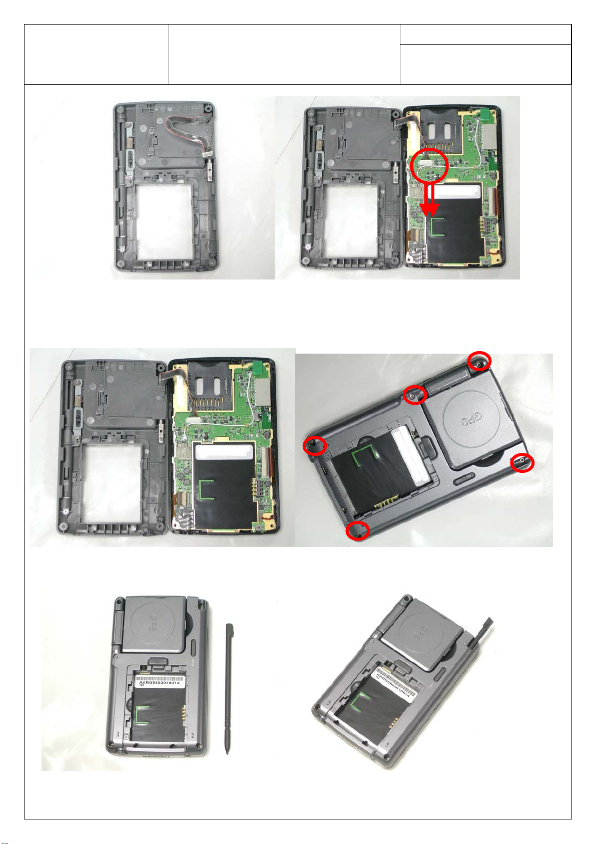
13. Slowly insert connector cable (PIC13.1, PIC13.2)
Page 17
Doc. No:
ASUSTeK COMPUTER INC.
PIC13.1 PIC13.2
14. Assemble the cover and secure 5 screws (PIC14.1, PIC14.2)
A63x Assembly & Disassembly
Guide
Date:
Rev.: Page:
16
PIC14.1 PIC14.2
15. Assemble Stylus (PIC15.1, PIC 15.2)
PIC15.1 PIC15.2
Page 18
Doc. No:
ASUSTeK COMPUTER INC.
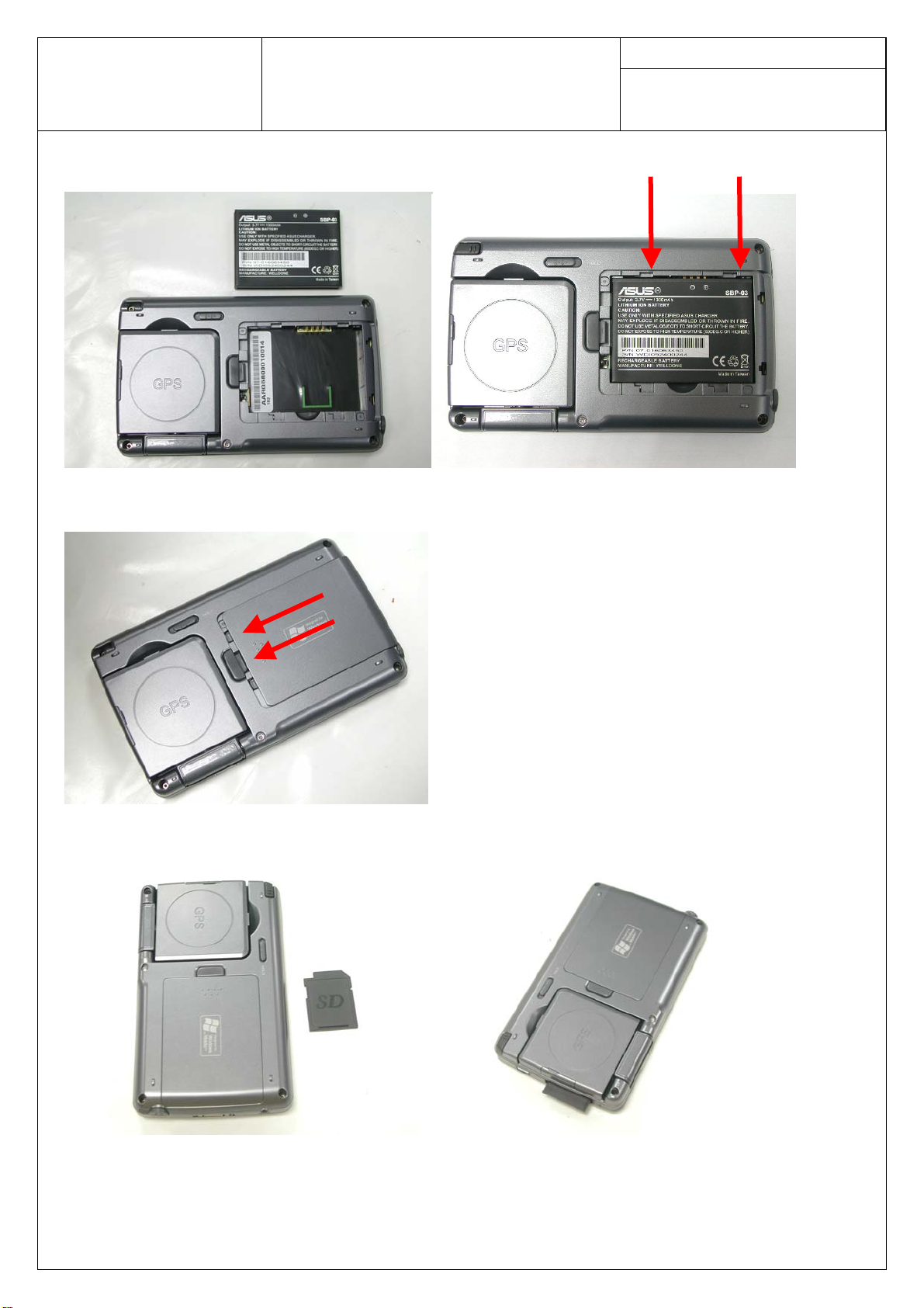
16. Insert the battery. (PIC16.1, PIC16.2)
PIC16.1 PIC16.2
17. Assemble battery cover (PIC17.1)
A63x Assembly & Disassembly
Guide
Date:
Rev.: Page:
17
PIC17.1
18. Insert SD card (PIC18.1, PIC18.2)
PIC18.1 PIC18.2
 Loading...