

Notebook PC
Hardware User’s Manual
E2014 / Apr 2005

Contents
1. Introducing the Notebook PC ..................................................................5
About This User’s Manual..........................................................................................6
Notes For This Manual..........................................................................................6
Preparing your Notebook PC.....................................................................................9
2. Knowing the Parts...................................................................................11
Front Side ................................................................................................................12
Top Side...................................................................................................................12
Left Side...................................................................................................................14
Right Side ................................................................................................................16
Rear Side .................................................................................................................18
Bottom Side .............................................................................................................19
3. Getting Started ....................................................................................... 21
Power System..........................................................................................................22
Using AC Power ..................................................................................................22
Using Battery Power............................................................................................23
Powering ON the Notebook PC ..........................................................................24
The Power-On Self Test (POST).........................................................................24
Battery Care ........................................................................................................24
Checking Battery Power......................................................................................25
Powering OFF the Notebook PC.........................................................................26
Restarting or Rebooting ......................................................................................26
Special Keyboard Functions ....................................................................................27
Colored Hot Keys ................................................................................................27
Keyboard as Cursors...........................................................................................28
Microsoft Windows™ Keys .................................................................................28
Keyboard as a Numeric Keypad .........................................................................29
Instant Launch Keys and Status Indicators .............................................................29
Instant Launch Keys............................................................................................29
Status Indicators (top–right) ................................................................................30
Status Indicators (front).......................................................................................31
CD Player Control Buttons and Indicator ............................................................32
4. Using the Notebook PC ......................................................................... 33
Operating System ....................................................................................................34
Support Software.................................................................................................34
2

Contents
Pointing Device ........................................................................................................34
Using the Touchpad.............................................................................................35
Touchpad Usage Illustrations ..............................................................................36
Caring for the Touchpad ......................................................................................37
Removing a PC Card (PCMCIA).........................................................................38
Inserting a PC Card (PCMCIA) ...........................................................................38
Storage Devices.......................................................................................................39
PC Card (PCMCIA) Socket .................................................................................39
Optical Drive........................................................................................................41
Hard Disk Drive ...................................................................................................42
Flash Memory Card Reader................................................................................42
Modem Connection .............................................................................................42
Fast-Ethernet Connection ...................................................................................45
Power Management Modes .....................................................................................45
Full Power Mode & Maximum Performance........................................................45
ACPI ....................................................................................................................45
Suspend Mode ....................................................................................................45
Power Savings ....................................................................................................45
Power State Summary ........................................................................................46
Thermal Power Control .......................................................................................46
Stand by and Hibernate.......................................................................................46
Notebook PC Upgrades ...........................................................................................48
Processor Upgrades............................................................................................49
System Fans and Processor ...............................................................................49
Thermal Power Control .......................................................................................49
Remove this fan set to access the memory banks. ............................................49
System Memory Expansion.................................................................................50
Hard Disk Drive Upgrades ..................................................................................50
Removing the optical disk drive ..........................................................................52
Appendix..................................................................................................... 53
Optional Accessories ...............................................................................................54
Optional Connections...............................................................................................57
DVD-ROM Drive Information ...................................................................................59
Internal Modem Compliancy ....................................................................................60
Glossary...................................................................................................................62
Declarations and Safety Statements .......................................................................66
Notebook PC Information.........................................................................................74
3

Contents
4

1. Introducing the Notebook PC
About This User’s Manual
Notes For This Manual
Safety Precautions
Preparing your Notebook PC
5
1 Introducing the Notebook PC
About This User’ s Manual
You are reading the Notebook PC User ’s Manual. This User’s Manual provides information on the
various components in the Notebook PC and how to use them. The following are major sections of this
User’s Manuals:
1. Introducing the Notebook PC
Introduces you to the Notebook PC and this User’s Manual.
2. Knowing the Parts
Gives you information on the Notebook PC’s components.
3. Getting Started
Gives you information on getting started with the Notebook PC.
4. Using the Notebook PC
Gives you information on using the Notebook PC’s components.
5. Appendix
Introduces you to optional accessories and gives additional information.
User’s Manual
Notes For This Manual
A few notes and warnings in bold are used throughout this guide that you should be aware of in order to
complete certain tasks safely and completely. These notes have different degrees of importance as
described below:
TIP: Tips and useful information for
completing tasks.
NOTE: Tips and information for special situations.
< >
[ ]
WARNING! Important information that
must be followed for safe operation.
IMPORTANT! Vital information that
must be followed to prevent damage
to data, components, or persons.
T ext enclosed in < > or [ ] represents a key on the keyboard; do not actually type the <
> or [ ] and the enclosed letters.
6
Introducing the Notebook PC 1
Safety Precautions
The following safety precautions will increase the life of the Notebook PC. Follow all precautions and
instructions. Except as described in this manual, refer all servicing to qualified personnel. Do not use
damaged power cords, accessories, or other peripherals. Do not use strong solvents such as thinners,
benzene, or other chemicals on or near the surface.
Disconnect the AC power and remove the battery pack(s) before cleaning. Wipe the
Notebook PC using a clean cellulose sponge or chamois cloth dampened with a solution of nonabrasive detergent and a few drops of warm water and remove any extra
moisture with a dry cloth.
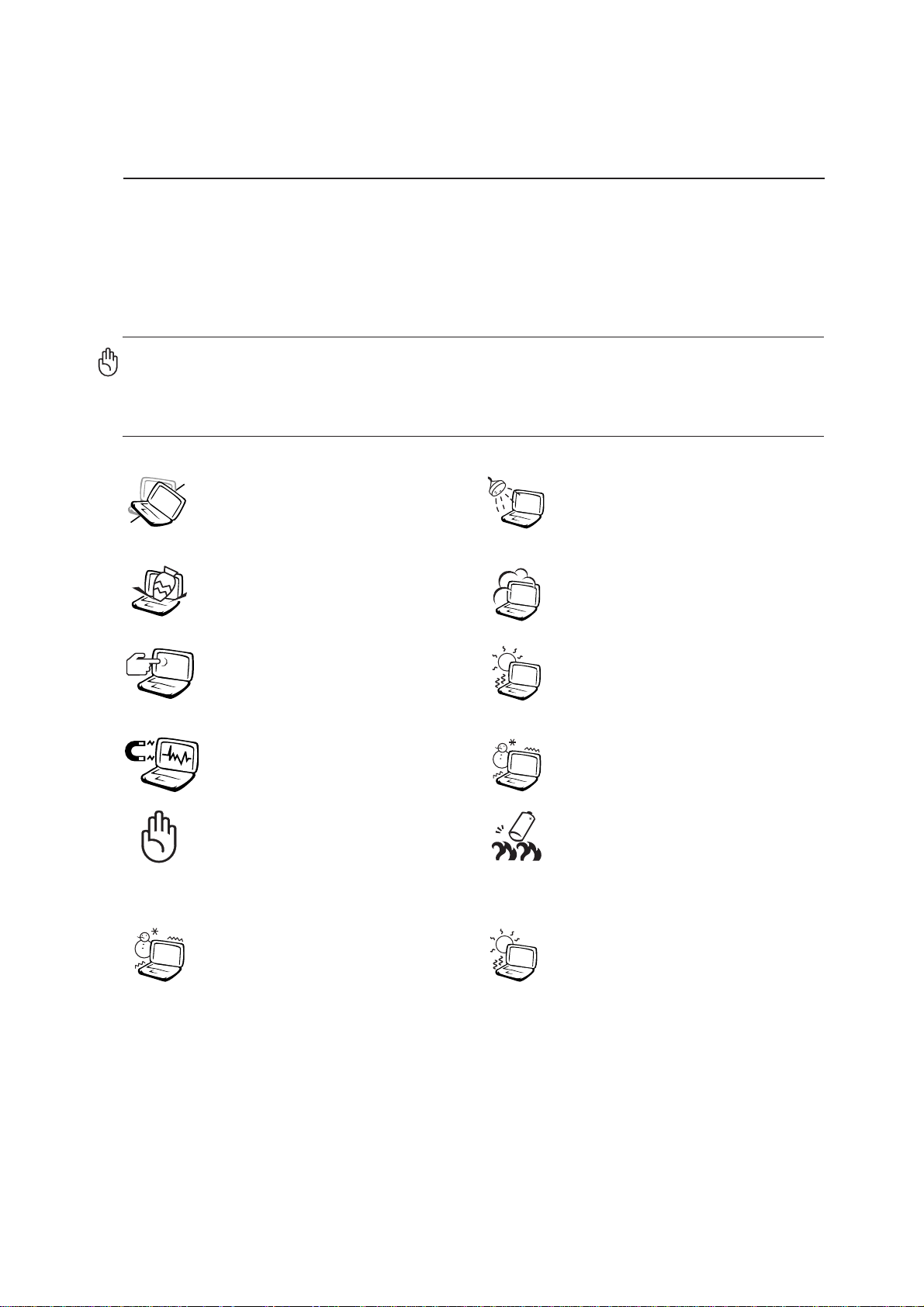
DO NOT place on uneven or unstable
work surfaces. Seek servicing if the
casing has been damaged.
DO NOT place or drop objects on top
and do not shove any foreign objects
into the Notebook PC.
DO NOT press or touch the display
panel. Do not place together with small
items that may scratch or enter the Notebook PC.
DO NOT expose to strong magnetic
or electrical fields.
DO NOT leave the Notebook PC on
your lap or any part of the body while
the Notebook PC is turned ON or is
charging in order to prevent discomfort or injury from heat exposure.
DO NOT expose to or use near liquids, rain, or moisture. DO NOT use
the modem during an electrical storm.
DO NOT expose to dirty or dusty environments. DO NOT operate during
a gas leak.
DO NOT expose to extreme temperatures
above 50˚C (122˚F) or to direct sunlight.
Do not block the fan vents!
DO NOT expose to extreme temperatures (below 0˚C (32˚F), otherwise the
Notebook PC may not boot.
DO NOT throw batteries in fires as
they may explode. Check local codes
for special battery disposal instructions.
0°C/32°F
Safe Operating Temperatures: This
notebook PC should be used in environments with ambient temperatures
between 0°C/32°F and 30°C/86°F.
30°C/86°F
7
1 Introducing the Notebook PC
Transportation Precautions
T o prepare the Notebook PC for transport, you should turn it OFF and disconnect all external peripherals to prevent damage to the connectors. The hard
disk drive’s head retracts when the power is turned OFF to prevent scratching
of the hard disk surface during transport. Therefore, you should not transport
the Notebook PC while the power is still ON. Close the display panel and check
that it is latched securely in the closed position to protect the keyboard and
display panel.
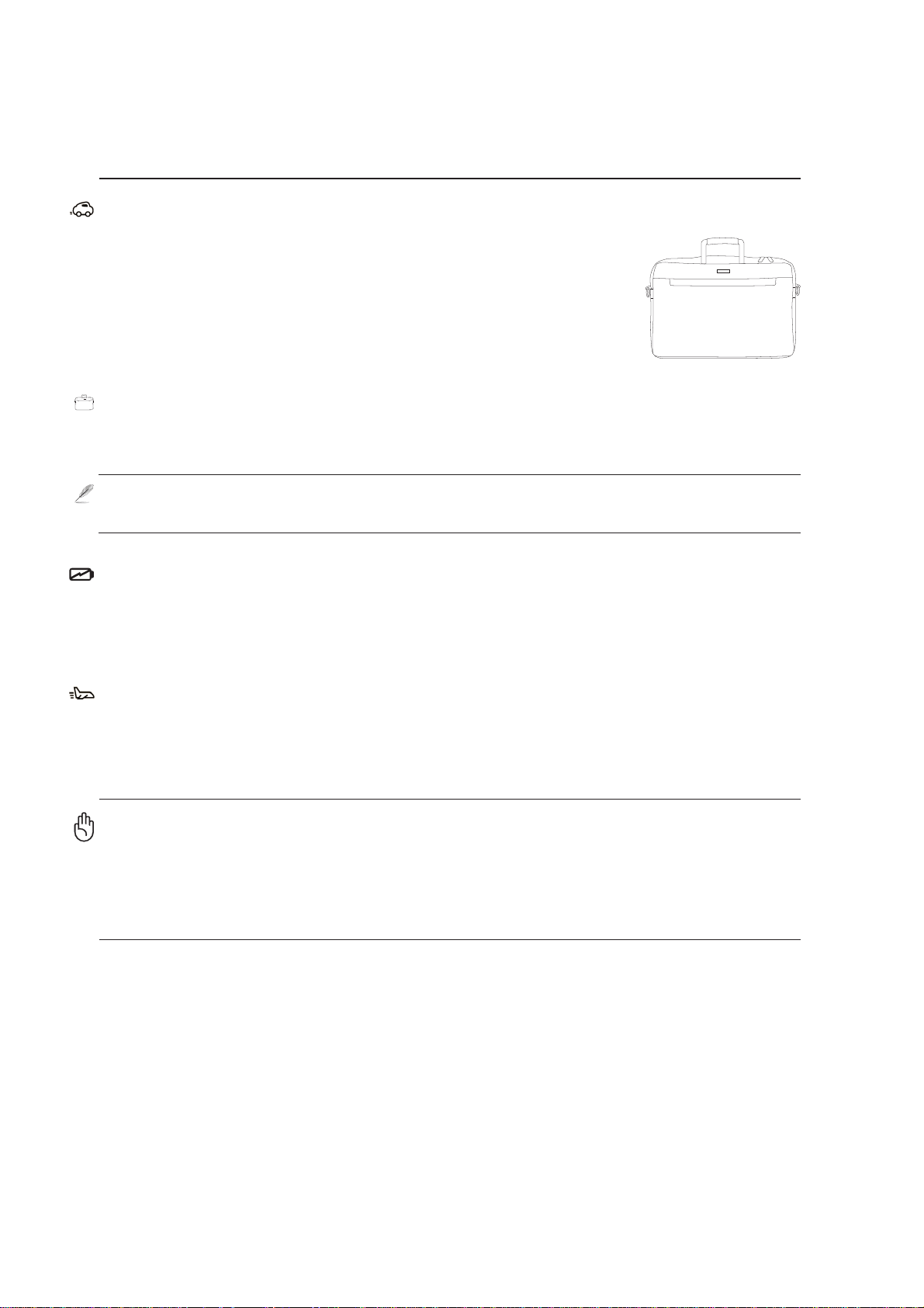
Cover Your Notebook PC
Use a carrying case such as the one supplied with your Notebook PC to protect it from dirt, water,
shock, and scratches.
NOTE: The surface glaze is easily dulled if not properly cared for. Be careful not to rub
or scrap the Notebook PC surfaces when transporting your Notebook PC.
Charge Your Batteries
If you intend to use battery power, be sure to fully charge your battery pack and any optional battery
packs before going on long trips. Remember that the power adapter charges the battery pack as long as
it is plugged into the computer and an AC power source. Be aware that it takes much longer to charge
the battery pack when the Notebook PC is in use.
Airplane Precautions
Contact your airline if you want to use the Notebook PC on the airplane. Most airlines will have restrictions for using electronic devices. Most airlines will allow electronic use only between and not during
takeoffs and landings.
CAUTION! There are three main types of airport security devices: X-ray machines
(used on items placed on conveyor belts), magnetic detectors (used on people walking through security checks), and magnetic wands (hand-held devices used on people
or individual items). Y ou can send your Notebook PC and diskettes through airport Xray machines. However, it is recommended that you do not send your Notebook PC or
diskettes through airport magnetic detectors or expose them to magnetic wands.
8
Introducing the Notebook PC 1
321
123
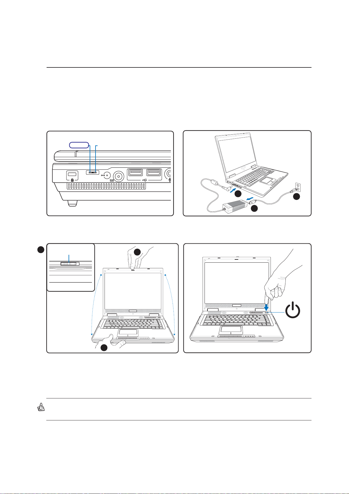
Preparing your Notebook PC
These are only quick instructions for using your Notebook PC. Read the later pages for detailed information on using your Notebook PC.
1. Unlock the battery power.
UnLock
Lock
2. Connect the AC Power Adapter
3. Open the Display Panel 4. Turn ON the Notebook PC
Display release latch
Slide the display release latch to unlock.
Lift the display panel with one hand while hold-
ing the system portion with your other hand.
WARNING! When opening, do not force the display panel down to the table or else
the hinges may break! Never lift the Notebook PC by the display panel!
Press the power button and release.
(In Windows XP, this button can also be used to
safely turn OFF the Notebook PC.)
9

1 Introducing the Notebook PC
10

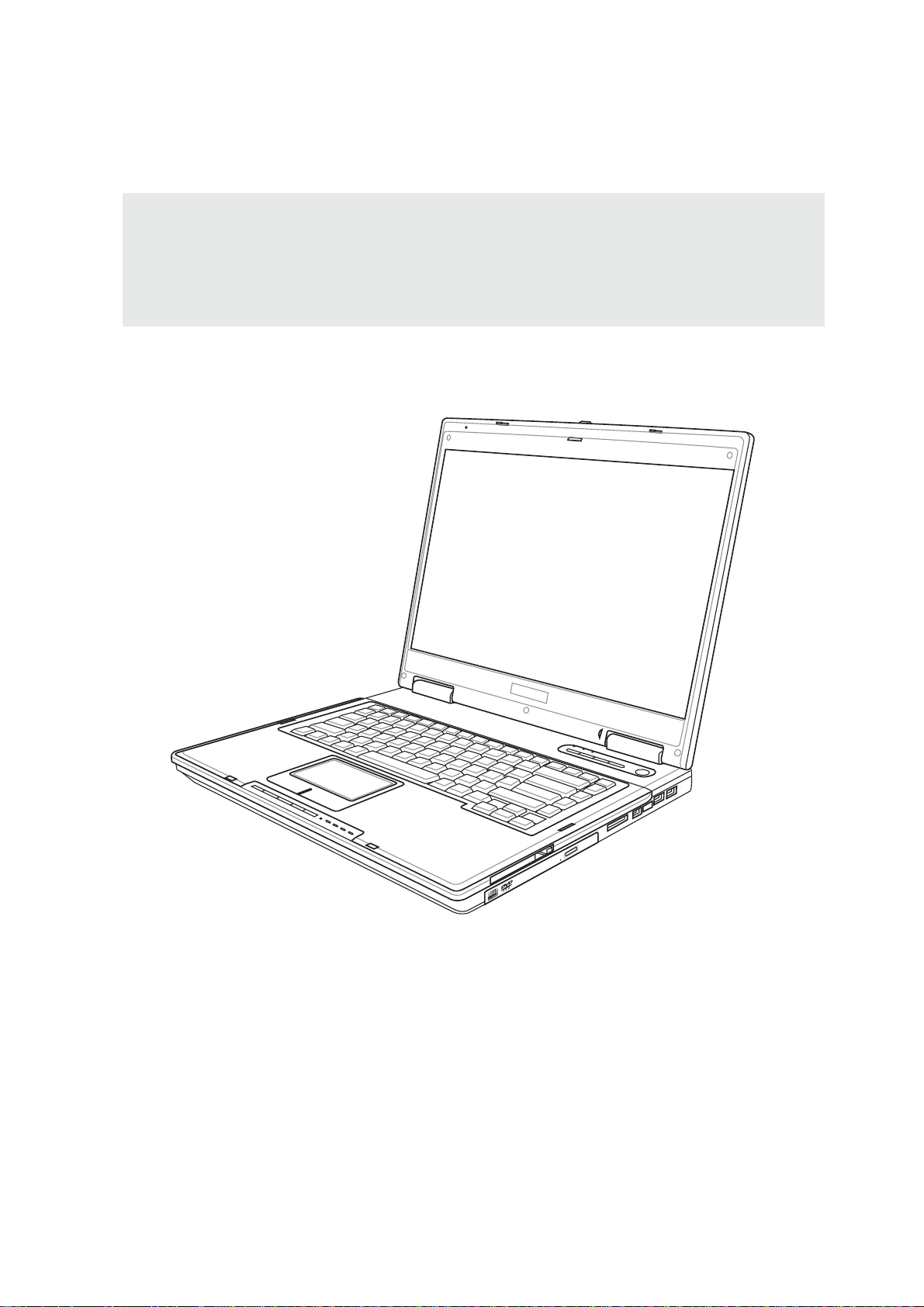
2. Knowing the Parts
Basic sides of the Notebook PC
11
2 Knowing the Parts
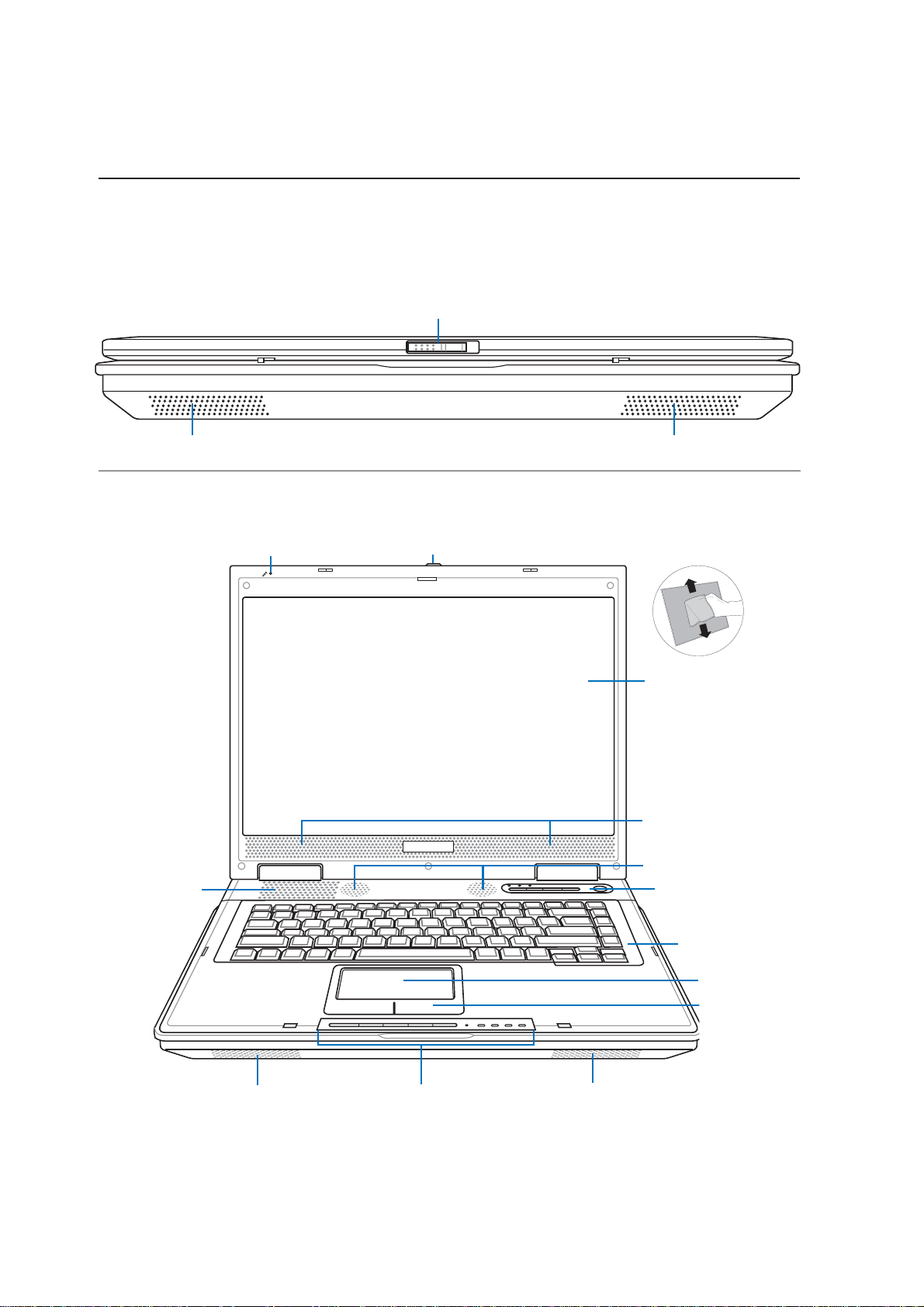
Front Side
Refer to the diagram below to identify the components on this side of the Notebook PC. Details are
given starting from the top and going clockwise.
Display Panel Latch Release
Air Vents
Top Side
Air Vents
Microphone
Display Panel Latch Release
Air Vents
Display Panel (Use a soft
cloth without chemical
liquids to clean. Use plain
water if necessary.)
Stereo Speakers
(on selected models)
Stereo Speakers
Power Switch, Instant
Keys, Status Indicators
(see section 3)
12
Air Vents
CD player controls and Status
Indicators (see section 3)
Air Vents
Keyboard
Touchpad
Touchpad
buttons
Knowing the Parts 2
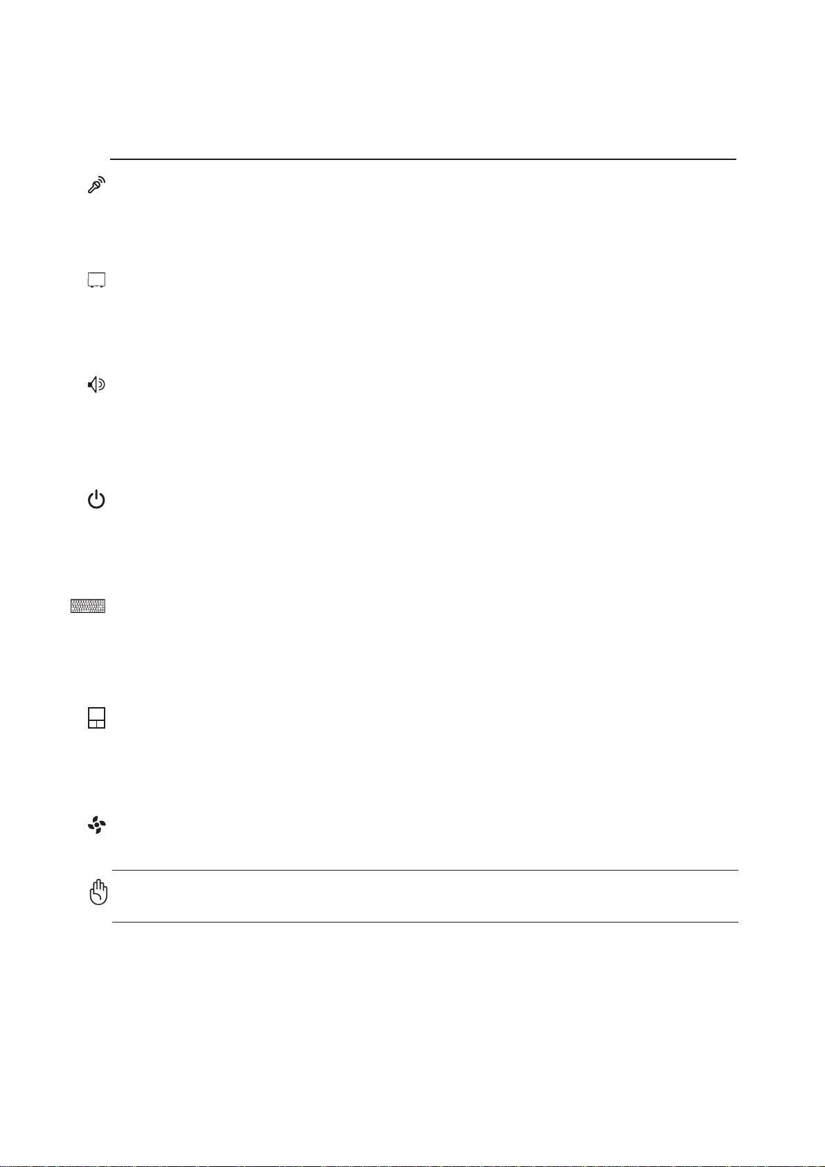
Microphone
The built-in microphone provides a source for general note taking, voice mail recording, or for use with
Internet phone software. An external microphone connection is also provided for use with your own
audio input device.
Display Panel
The display panel functions the same as a desktop monitor. The Notebook PC uses an active matrix
TFT LCD, which provides excellent viewing like that of desktop monitors. Unlike desktop monitors,
the LCD panel does not produce any radiation or flickering, so it is easier on the eyes.
Stereo Speakers
The built-in stereo speaker system allows you to hear audio without additional attachments. The multimedia sound system features an integrated digital audio controller that produces rich, vibrant sound
(results improved with external stereo headphones or speakers). Audio features are software controlled.
Power Switch
The power switch allows powering ON and OFF the Notebook PC and recovering from STD. Push the
switch once to turn ON and once to turn OFF the Notebook PC. The power switch only works when the
display panel is opened.
Keyboard
The keyboard provides full-sized keys with comfortable travel (depth at which the keys can be depressed) and palm rest for both hands. T wo W indows™ function keys are provided to help ease navigation in the Windows™ operating system.
Touchpad and Buttons
The touchpad with its buttons is a pointing device that provides the same functions as a desktop mouse.
A software-controlled scrolling function is available after setting up the included touchpad utility to
allow easy Windows or web navigation.
Air Vents
The air vents allow cool air to enter and warm air to exit the Notebook PC.
IMPORTANT! Make sure that paper, books, clothing, cables, or other objects do not
block any of the air vents or else overheating of the Notebook PC may occur.
13

2 Knowing the Parts
Left Side
Refer to the diagram below to identify the components on this side of the Notebook PC.
®
Kensington
Lock Port
Emergency
Shutdown
USB Ports
Battery Power
Switch
DC Power
Input Jack
Mic Input Phone Output
Kensington® Lock Port
The Kensington® lock port allows the Notebook PC to be secured using Kensington® compatible Notebook PC security products. These security products usually include a metal cable and lock that prevent
the Notebook PC to be removed from a fixed object. Some security products may also include a motion
detector to sound an alarm when moved.
Battery Power Switch
The battery power switch allows locking the battery pack power for safe transportation, storage, upgrades, or repairs.
Emergency Shutdown Button
In case your operating system cannot properly turn OFF or restart, the shutdown button can be pressed
with a straightened paper clip to shutdown the Notebook PC.
Power (DC) Input
The supplied power adapter converts AC power to DC power for use with this jack. Power supplied
through this jack supplies power to the Notebook PC and charges the internal battery pack. To prevent
damage to the Notebook PC and battery pack, always use the supplied power adapter.
14

Knowing the Parts 2
USB Port (2.0/1.1)
The Universal Serial Bus is compatible with USB 2.0 or USB 1.1 devices such as keyboards, pointing
devices, video cameras, modems, hard disk drives, printers, monitors, and scanners connected in a
series up to 12Mbits/sec (USB 1.1) and 480Mbits/sec (USB 2.0). USB allows many devices to run
simultaneously on a single computer, with peripherals such as USB keyboards and some newer monitors acting as additional plug-in sites or hubs. USB supports hot-swapping of devices so that peripherals can be connected or disconnected without restarting the computer.
Microphone Input Jack (Mic In)
The mono microphone jack (1/8 inch) can be used to connect an external microphone or output signals
from audio devices. Using this jack automatically disables the built-in microphone. Use this feature for
video conferencing, voice narrations, or simple audio recordings.
Headphone Output Jack (Phone Output)
The stereo headphone jack (1/8 inch) is used to connect the Notebook PC’s audio out signal to amplified speakers or headphones. Using this jack automatically disables the built-in speakers.
15
2 Knowing the Parts
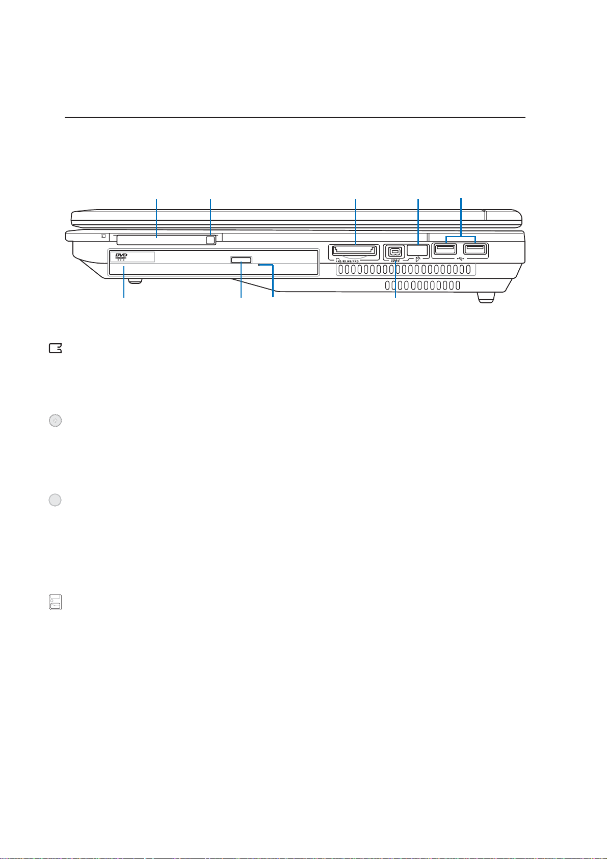
Right Side
Refer to the diagram below to identify the components on this side of the Notebook PC.
PC Card Slot PC Card Eject Flash Memory Slot
Optical Drive
(varies by model)
Electronic
Eject
Emergency
Eject
Infrared Port USB Ports
1394 Port
PC Card Slot
One PCMCIA 2.1 compliant PC Card socket is available to support one type I/II PC card. The socket
supports 32-bit CardBus. This allows accommodation of Notebook PC expansion options such as memory
cards, ISDN, SCSI, Smart Cards, and wireless network adapters.
Optical Drive
The Notebook PC comes in various models with different optical drives. The Notebook PC’s optical
drive may support compact discs (CD) and/or digital video discs (DVD) and may have recordable (R)
or re-writable (RW) capabilities. See the marketing specifications for details on each model.
Electronic Eject, Emergency Eject (Optical Drive)
The optical drive eject has an electronic eject button for opening the tray . You can also eject the optical
drive tray through any software player or by right clicking the optical drive in Windows™ “My Computer.” The emergency eject is used to eject the optical drive tray in case the electronic eject does not
work. Do not use the emergency eject in place of the electronic eject. The activity LED (not available
on some models) lights in proportion to the data transferred between the Notebook PC and optical disc.
Flash Memory Slot
Normally a PCMCIA or USB memory card reader must be purchased separately in order to use memory
cards from devices such as digital cameras, MP3 players, mobile phones, and PDAs. This Notebook PC
has a built-in memory card reader that can read many flash memory cards as specified later in this
manual. The built-in memory card reader is not only convenient, but also faster than most other forms
of memory card readers because it utilizes the high-bandwidth PCI bus.
16

Knowing the Parts 2
1394 Port
IEEE1394 is a high speed serial bus like SCSI but has simple connections and hot-plugging capabilities
like USB. The interface IEEE1394 has a bandwidth of 100-400 Mbits/sec and can handle up to 63 units
on the same bus. IEEE1394 is also used in high-end digital equipment and should be marked “DV” for
Digital V ideo port.
Infrared Port (IrDA)
The infrared (IrDA) communication port allows convenient wireless data communication with infrared-equipped devices or computers. This allows easy wireless synchronization with PDAs or mobile
phones and even wireless printing to printers. If your office supports IrDA networking, you can have
wireless connection to a network anywhere provided there is a direct line of sight to an IrDA node.
Small offices can use IrDA technology to share a printer between several closely placed Notebook PCs
and even send files to each other without a network.
USB Port (2.0/1.1)
The Universal Serial Bus is compatible with USB 2.0 or USB 1.1 devices such as keyboards, pointing
devices, video cameras, modems, hard disk drives, printers, monitors, and scanners connected in a
series up to 12Mbits/sec (USB 1.1) and 480Mbits/sec (USB 2.0). USB allows many devices to run
simultaneously on a single computer, with peripherals such as USB keyboards and some newer monitors acting as additional plug-in sites or hubs. USB supports hot-swapping of devices so that peripherals can be connected or disconnected without restarting the computer.
17
2 Knowing the Parts
On selected models
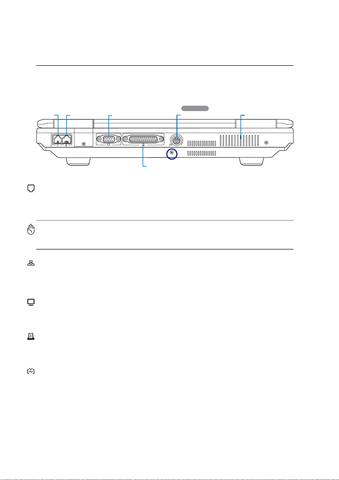
Rear Side
Refer to the diagram below to identify the components on this side of the Notebook PC.
Modem Port
LAN Port
Monitor Port
TV Out Port
Parallel Port
Air Vents
Modem Port
The RJ-11 modem port with two pins is smaller than the RJ-45 LAN port and supports a standard
telephone cable. The internal modem supports up to 56K V.90 transfers. The built-in connector allows
convenient use without additional adapters.
IMPORT ANT! The built-in modem does not support the voltage used in digital phone
systems. Do not connect the modem port to a digital phone system or else damage
will occur to the Notebook PC.
LAN Port
The RJ-45 LAN port with eight pins is larger than the RJ-11 modem port and supports a standard
Ethernet cable for connection to a local network. The built-in connector allows convenient use without
additional adapters.
Display (Monitor) Output
The 15-pin D-sub monitor port supports a standard VGA-compatible device such as a monitor or projector to allow viewing on a larger external display.
Parallel Port
The 25-pin D-sub parallel/printer port supports native parallel devices such as laser/inkjet printers, or
parallel-adapted device such as external hard drives, removable drives, or scanners.
TV-Out Port (on selected models)
The TV-Out port is an S-Video connector that allows routing the Notebook PC’ s display to a television
or video projection device. You can choose between simultaneouly or single display. Use an S-Video
cable (not provided) for high quality displays or use the provided RCA to S-Video adapter for standard
video devices. This port supports both NTSC and PAL formats.
18
Knowing the Parts 2
OPEN
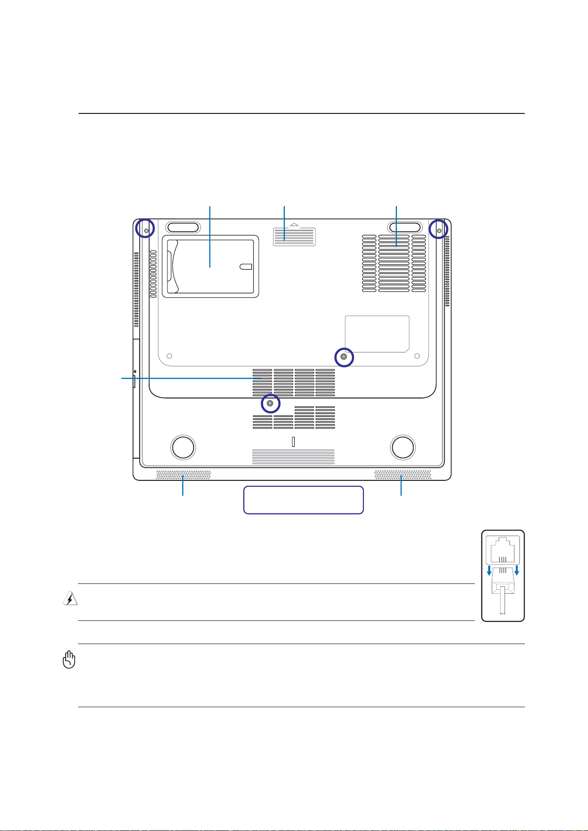
Bottom Side
Refer to the diagram below to identify the components on this side of the Notebook PC. Details are
given starting from the top and going clockwise.
Air Vents
Name Card Holder
Bottom cover
removal tab
Air Vents
Bottom cover screws are circled
Air Vents
in this illustration. One screw is
located on the rear side.
Air Vents
Bottom Panel Screws
This notebook PC contains easy to install/upgrade components under the bottom cover. Several screws must be removed to open the bottom panel. One screw is located on the rear side.
WARNING! Because telephone lines carry electrical current, you must remove the phone (modem) cable before removing the bottom cover.
IMPORT ANT! The bottom of the Notebook PC can get very hot. Be careful when handling the Notebook PC while it is in operation or recently been in operation. High
temperatures are normal during charging or operation. DO NOT PUT THE NOTEBOOK
PC ON THE LAP OR OTHER P ARTS OF THE BODY T O AVOID INJURY FROM THE HEA T.
19

2 Knowing the Parts
20

3. Getting Started
Using AC Power
Using Battery Power
Powering ON the Notebook PC
Checking Battery Power
Restarting or Rebooting
Powering OFF the Notebook PC
Special Keyboard Functions
Instant Keys and Status Indicators
21
3 Getting Started
321
Power System
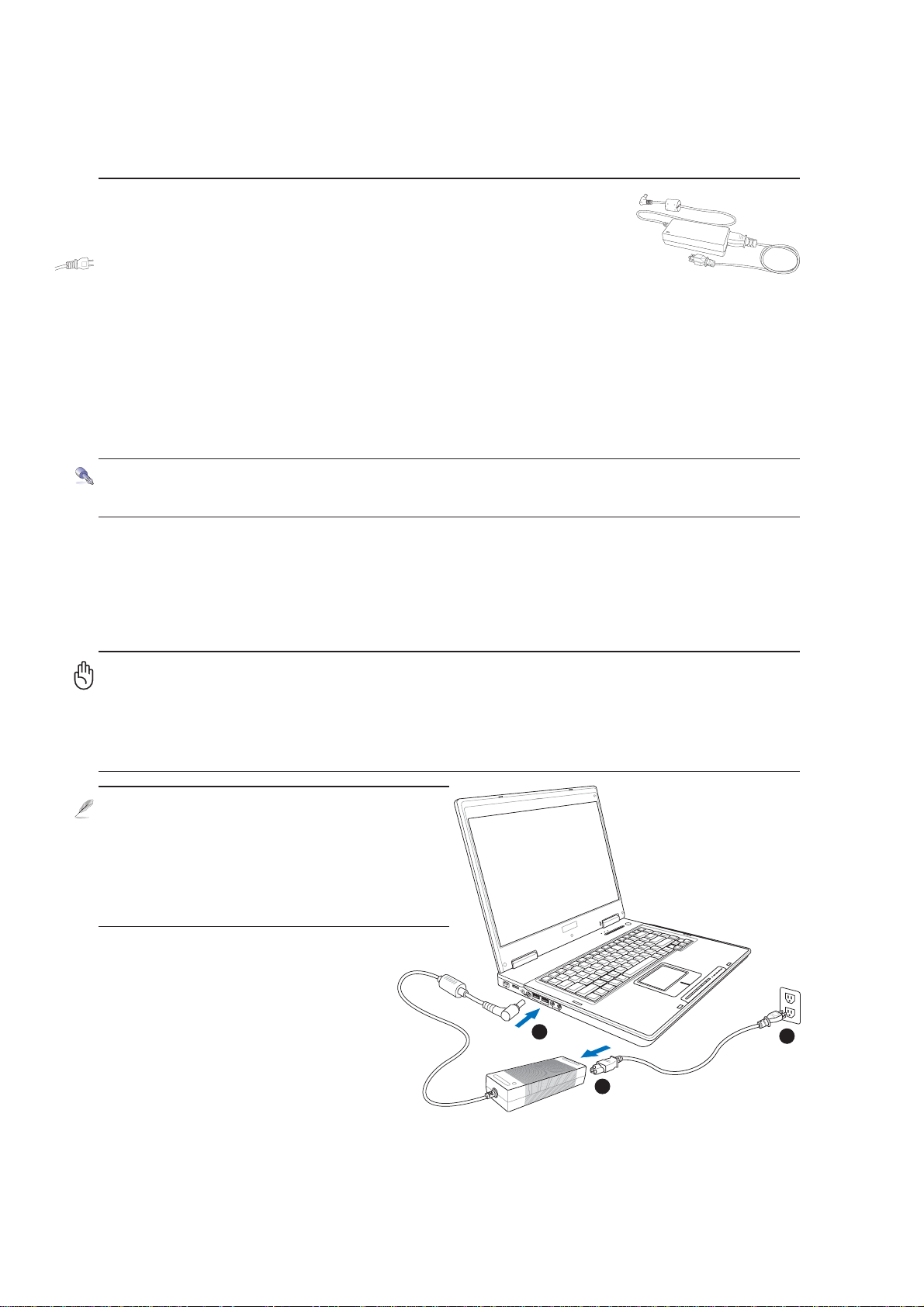
Using AC Power
The Notebook PC power is comprised of two parts, the power adapter and the battery power system.
The power adapter converts AC power from a wall outlet to the DC power required by the Notebook
PC. Your Notebook PC comes with a universal AC-DC adapter. That means that you may connect the
power cord to any 100V-120V as well as 220V-240V outlets without setting switches or using power
converters. Different countries may require that an adapter be used to connect the provided US-standard AC power cord to a dif ferent standard. Most hotels will provide universal outlets to support differ ent power cords as well as voltages. It is always best to ask an experienced traveler about AC outlet
voltages when bringing power adapters to another country.
TIP: You can buy travel kits for the Notebook PC that includes power and modem
adapters for almost every country.
With the AC power cord connected to the AC-DC converter , connect the AC power cord to an AC outlet
(preferably with surge-protection) and then connect the DC plug to the Notebook PC. Connecting the
AC-DC adapter to the AC outlet first allows you to test the AC outlet’s power and the AC-DC converter
itself for compatibility problems before connecting the DC power to the Notebook PC. The green
power LED on the adapter lights up if the power is within accepted ranges.
IMPORTANT! Damage may occur if you use a different adapter to power the Notebook PC or use the Notebook PC’s adapter to power other electrical devices. If there
is smoke, burning scent, or extreme heat coming from the AC-DC adapter, seek servicing. Seek servicing if you suspect a faulty AC-DC adapter. You may damage both
your battery pack(s) and the Notebook PC with a faulty AC-DC adapter.
NOTE: This Notebook PC may come with
either a two or three-prong plug depending on territory . If a three-prong plug is provided, you must use a grounded AC outlet
or use a properly grounded adapter to ensure safe operation of the Notebook PC.
22
Getting Started 3
Using Battery Power
The Notebook PC is designed to work with a removable battery pack. The battery pack consists of a set
of battery cells housed together. A fully charged pack will provide several hours of battery life, which
can be further extended by using power management features through the BIOS setup. Additional
battery packs are optional and can be purchased separately through a Notebook PC retailer.
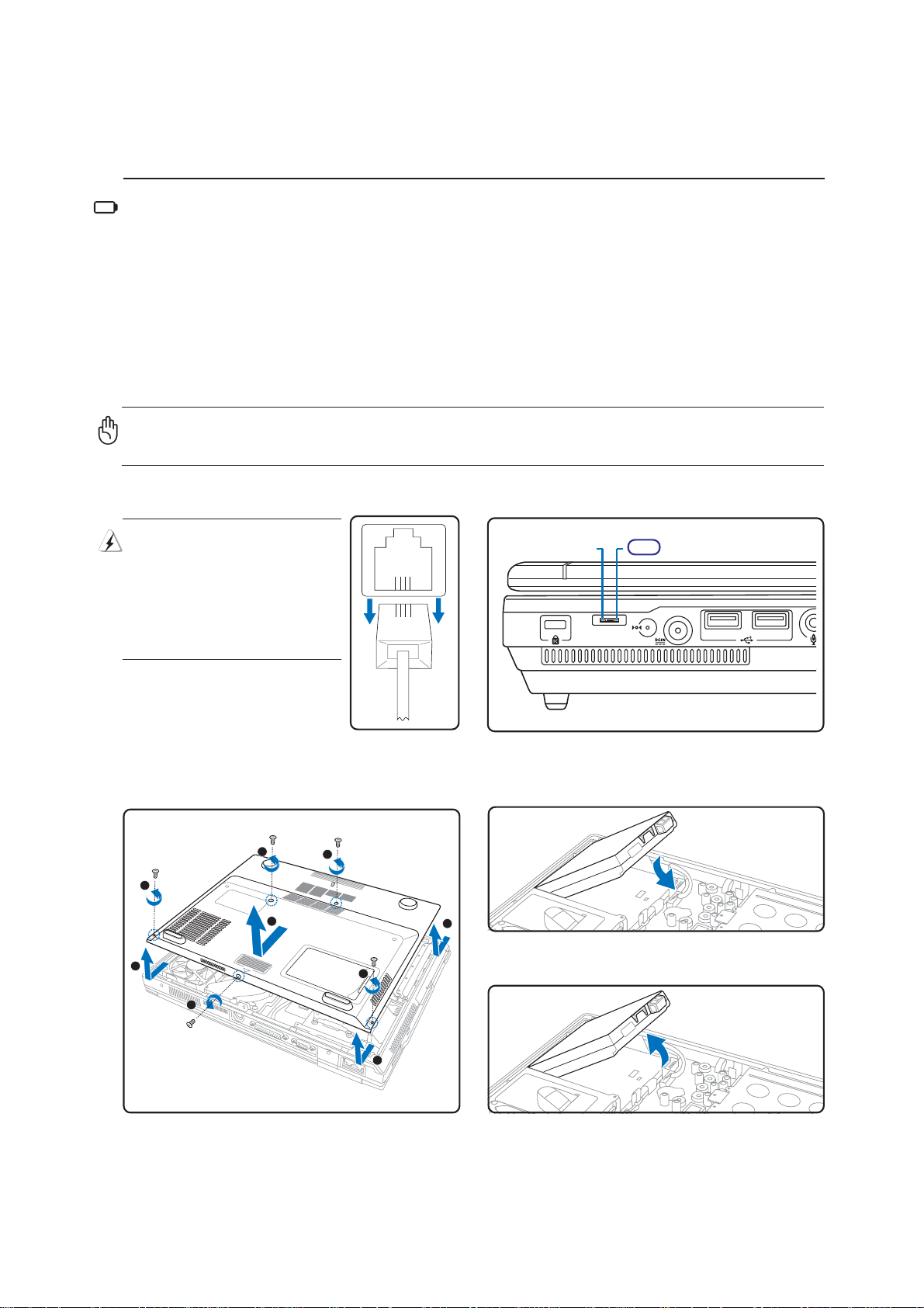
Installing and Removing the Battery Pack
Your Notebook PC may or may not have its battery pack installed. If your Notebook PC does not have
its battery pack installed, use the following procedures to install the battery pack.
IMPORTANT! Never attempt to remove the battery pack while the Notebook PC is
turned ON, as this may result in the loss of working data.
1. Remove all cables.
WARNING! Because telephone lines carry electrical current, you must remove the phone (modem)
cable before removing
the bottom cover.
3. Remove the following screws.
1
1
2
1
2. Lock the battery power.
UnLock
Lock
Installing the battery pack: Insert the outer side
and then press down on the inner side.
2
2
1
OPEN
1
2
side.
23
Removing the battery pack: Lift from the inner
 Loading...