

Page 1
ASURO - 1
-
ASURO
AREXX, Zwolle - NETHERLANDS
JAMA, Taichung - TAIWAN
www.arexx.com
Assembly and Operation MANUAL
AREXX - The Netherlands
AREXX - The Netherlands
Page 2
ASURO - 2
WARNING
* When you open the parts the return right will be disposed
* Read before you start assembly the instruction manual
* Be careful with tools
* Keep this product out of reach of children and do not build this kit when children are in
the neighbourhood, the tools and parts are dangerous for children
* Check the polarity of the batteries
* Keep the batteries dry, when the ASURO gets wet remove the batteries and let the
ASURO dry for some time
* Remove the batteries when you are not using the ASURO for a longer period
Introduction
ASURO is a mobile mini-robot, completely programmable in C and especially developed for education
at the German Aerospace Centre DLR, department for Robotics and Mechatronics. Assembly is easy
for experienced electronic technicians and feasible for a novice. Except for the printed circuit boards
(PCB) only standard parts for assembly will be used.
For programming we use freeware only. Therefore ASURO is exceptionally suitable as an introduction
into processor-controlled hobby electronics, for projects in schools and universities, for studies and
adult education centres. Special tools, which are freeware for private users, have been used for all
electronic development phases and software design, proving how robots can be designed without
using expensive tools or machines.
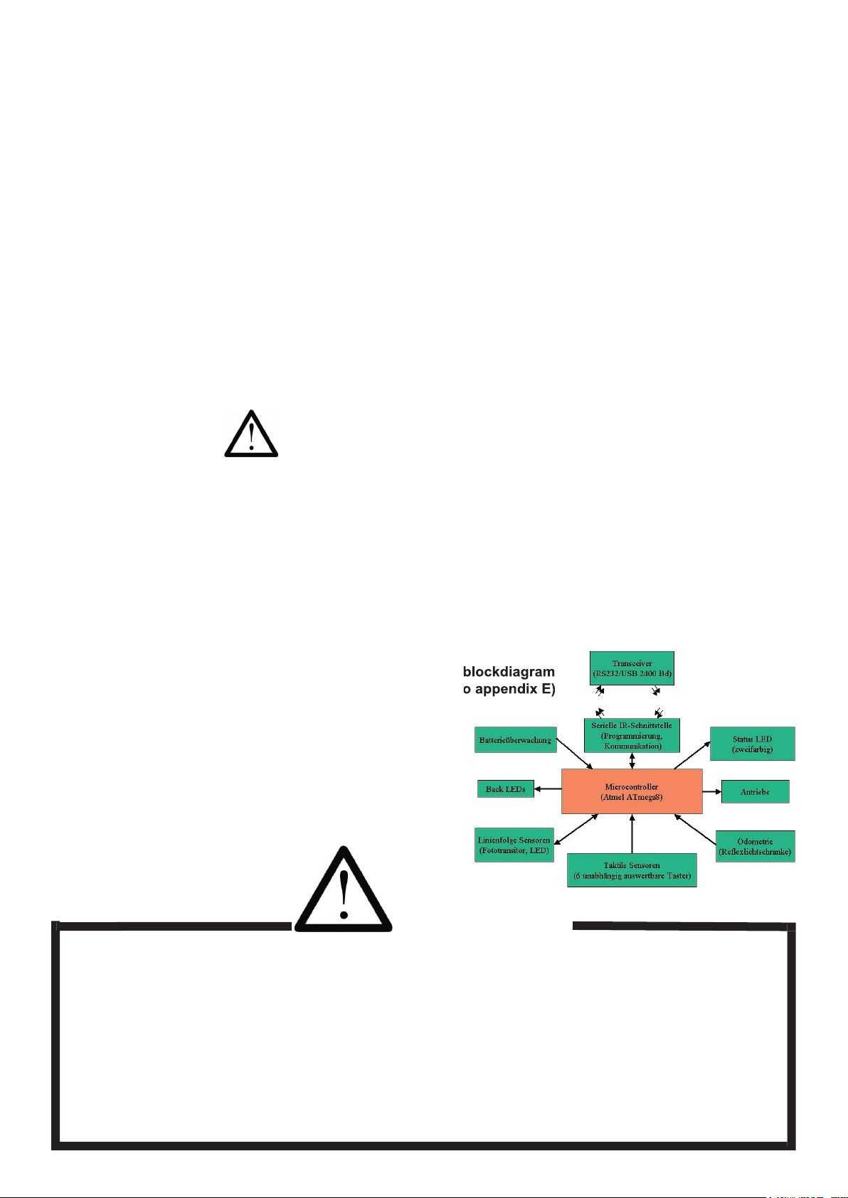
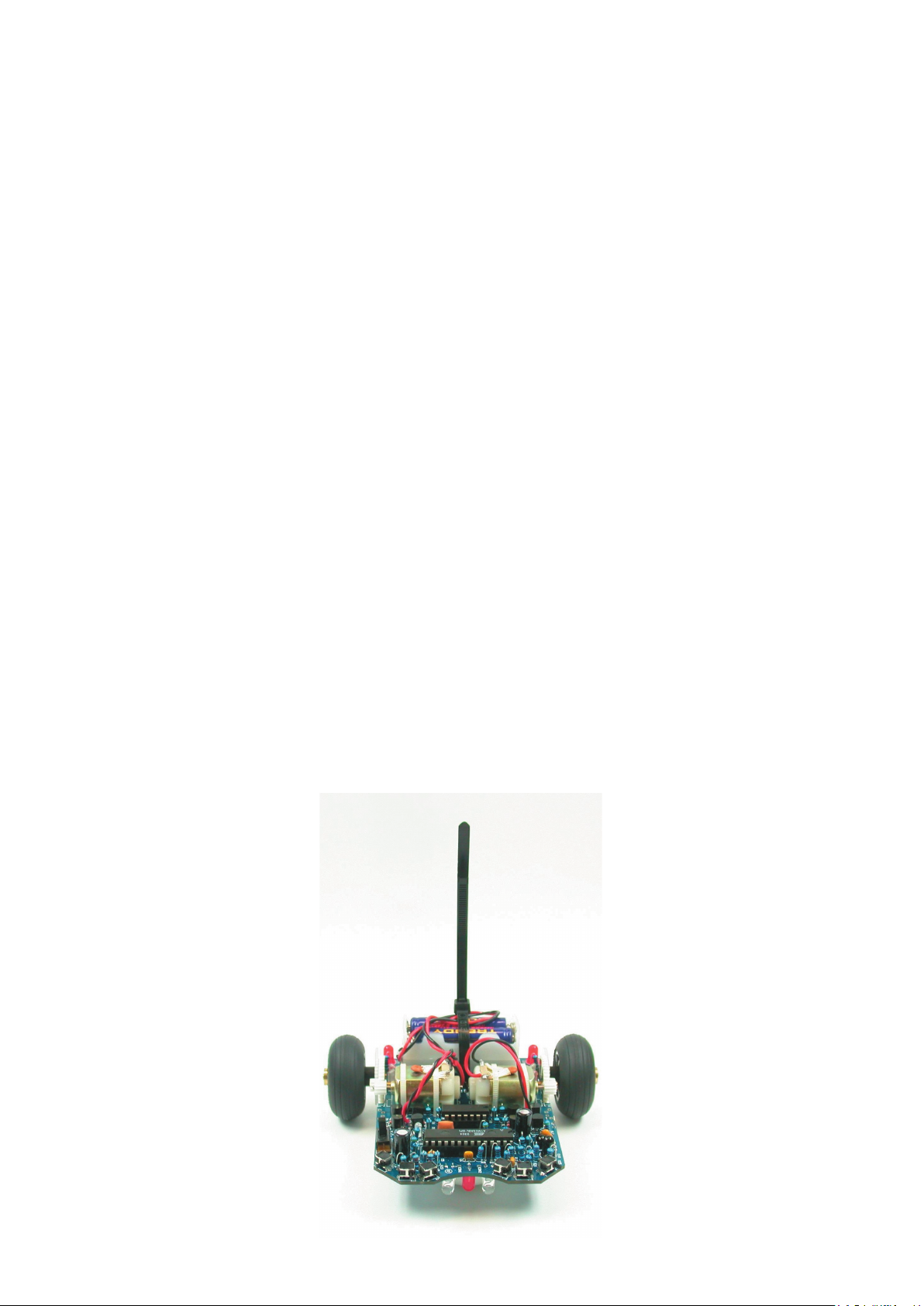
ASURO is equipped with a RISC-processor and two independently controlled motors, an optical linetracer, six collision-detector switches, two odometer-sensors, three optical displays and an infraredcommunication set for programming and remote control by a PC (see g.
0.1).
The Caution-symbol signalizes paragraphs with warnings, to be studied intensively, to
prevent damage to components or personal health.
We must inform all users, ASURO is no toy and is not to be handed out to children under the age of
three years, as they may swallow the dozens of small components.
Please provide some batteries and start the assembly!
And yes: ASURO is another way of saying: “Another Small and Unique Robot from Oberpfaffenhofen!”
© DLR & AREXX
Jan Grewe
Robin Gruber
WW.AREXX.COM
(see also appendix E)
Page 3

ASURO - 3
-
CONTENTS
I. Mechanics 6
1. Necessary tools 6
2. Mechanical preparations 7
2.1. Motorpinion 7
2.2. Table-tennis ball
7
2.3. Axles
8
2.4. Wheelsenors 8
II. Electronics 9
3. Soldering instructions 9
3.1. Tip, solder and temperature
9
3.2. Preparing parts 10
3.3. Soldering parts 11
3.4 De-soldering 12
4. Electronic assemly 13
4.1. Assembly RS232-Infrared-Transceiver
13
4.2. Optional USB-Infrared-Transceivers 15
4.3. Assembly ASURO-PCB 16
4.4. Attachment of the motors 20
4.5. Power supply 20
5. Preparation for operation 21
5.1. RS232-Infrared-Transceiver
21
5.2. USB-Infrared-Tranceiver 22
5.2.2. Linux 23
5.3. ASURO operation 24
5.3.1. Display-elements 25
5.3.2. Phototransistors (T9, T10)
25
5.3.3. Switches 26
5.3.4. Odometrie 26
5.3.5. The engine 26
5.3.6. IR interface 26
5.3.7. READY? 27
Page 4

ASURO - 4
6. Trouble shooting 28
6.1. Failure of RS232-IR-Transceiver ! 28
6.1.1. Activated key and displayed symbol do not match
28
6.1.2. The Terminal-Programm does not display any symbol
28
6.1.3. Still not working 28
6.2. USB-Infrared-Tranceiver does not work
28
6.3. Back-LEDs (D15,D16) glimmen nach dem Einschalten nicht! 28
6.3.1. Back-LEDs do not glow at start up 29
6.3.2. Only one of the back LEDs is glowing 29
6.3.3. Status-LED (D12) is not activated biocolored after start up 29
6.4. A display does not work 29
6.4.1. Status-LED D12 does not work 29
6.4.2. Front-LED D11 does not work
29
6.4.3. Left Back-LED D15 does not work 30
6.4.4. Rigth Back-LED D16 does not work 30
6.5. Linentracer (T9, T10) does not work 30
6.6. A switch does not work 30
6.6.1. Obviously a combination of switches has been activated 31
6.6.2. Display reacts if switches have been interchanged 31
6.6.3. Things still do not work well 31
6.7. The re ected light-sensor (odometer) does not work 31
6.7.1. None of the re ected light-sensors work 31
6.7.2. The left re ected light-sensors does not work 31
6.7.3. The left re ected light-sensors does not work 31
6.8. One motor does not move 32
6.8.1. Both motors do not move 32
6.8.2. Left motor does not move or only in one direction 32
6.8.3. Right motordoes not move or only in one direction 32
6.8.4. One motor rotates in reversed direction 32
6.9. IR-interface 32
6.9.1. ASURO does not send symbols
32
6.9.2. ASURO does not receive symbols 32
6.9.3. Things still do not work well 33
7. Final adjustments 34
Page 5

ASURO - 5
-
III. Software 35
8. Software installation and initial steps 35
8.1. WINDOWS 35
8.1.1 Installation Flash - the ASURO-Programmer-Tool 35
8.1.2 Installation of the editor and compiler 35
8.1.3. Example programs 39
8.2. LINUX 51
8.2.1. Installation Flash - the ASURO-Programmer-Tool 51
8.2.2. Compiler 52
8.3. Working with Flash
53
8.4. Flash failures 54
8.5. First step in Programming 54
9. C for ASURO 56
9.1. Basics in C-Programmierung 56
9.1.1. Introduction 56
9.1.2. Variables and datatypes
57
9.1.3. Compilerdirektives 59
9.1.4. Conditions 59
9.1.5. Loops 61
9.1.6. Functions 62
9.1.7. pointers and vectors 64
9.2. Overview of the ASURO functions 65
9.2.1. void Init(void) 66
9.2.2. void StatusLED (unsigned char color) 66
9.2.3. void FrontLED (unsigned char status) 67
9.2.4. void BackLED (unsigned char left, unsigned char right) 67
9.2.5. void Sleep (unsigned char time72kHz) 67
9.2.6. void MotorDir (unsigned char left_dir, unsigned char right_dir) 67
9.2.7. void MotorSpeed (unsigned char left_speed, unsigned char right_speed) 68
9.2.8. void SerWrite (unsigned char *data, unsigned char length) 68
9.2.9. void SerRead (unsigned char *data, unsigned char length, unsigned int timeout) 68
9.2.10. void LineData (unsigned int *data) 69
9.2.11. void OdometrieData (unsigned int *data) 70
9.2.12. unsigned char PollSwitch (void) 71
IV. Appendices 72
A. Partlist 72
B. Diagram ASURO
74
C. RS-232 IR Transceiver
75
D. USB IR-Transceiver
76
E. Blockdiagram ASURO
77
F. Blockdiagram PIC Processor
77
G. Contents ASURO KIT
78
Page 6
ASURO - 6
Part I. Mechanics
1. Necessary tools
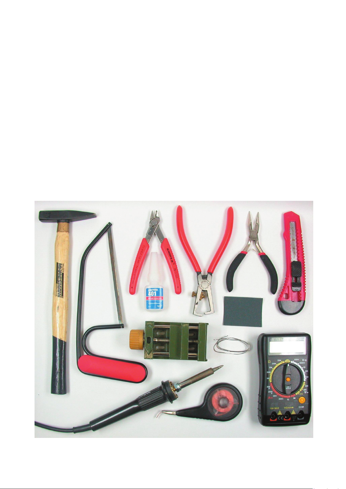
In order to build the ASURO we need – apart from the kit – the following tools:
• A „third hand“
• Stanley-Knife
• Small hammer
• Sandpaper (for ne work, Nr. 240)
• Long nose plier for electronic work
• Cutter for electronic cable work
• Soldering iron for electronic work (approx. 20-30 W) or a soldering station
• Solderwire (1 mm) for electronic work, optionally leadfree
• Desoldering wick (2-3 mm width), just in case solder has to be removed from the print
• Glue (either an instant 1-component glue, a bicomponent glue or a hot glue pistol)
• Computer: a laptop or personal computer (operated with Windows or Linux)
• Optionally: a multimeter
* For the optional USB IR-Transceiver you may need an USB cable A to B
Necessary tools
Page 7
ASURO - 7
-
2. Mechanical Preparations
Completeness of the kit must be checked rst. A parts list in appendix A has been provided
as a checklist. Before doing any electronic artwork, we must however do some mechanical
preparations. So let’s start working.
2.1. Motorpinion
Motor power is to be transmitted to the gear by small cogwheels (with drilling holes of 1.9 mm),
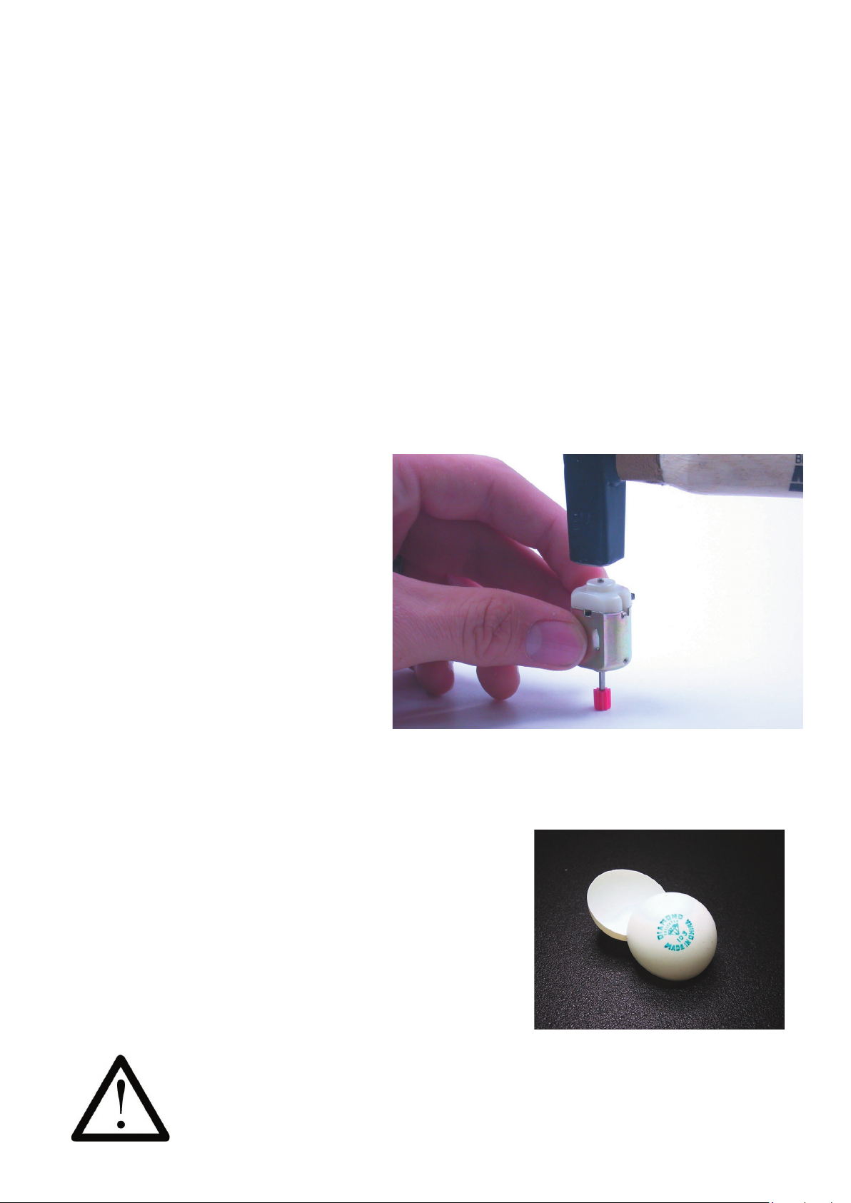
which have to be pressed onto the motor axles. Place the rounded side of the cogwheel on a at
surface and press the motor axle gently into the drilling hole of the cogwheel without using too
much force. You may use a small hammer to press the axle of the motor fully into the cogwheel, by
placing the cogwheel on a weaker surface ( eg. cardboard) and applying the hammer gently to the
backside axle of the motor (see g.
2.1).
Alternatively you may press the cogwheel to the motor axle by using the benchvice. Take care to
press the axle and not to apply any force to the case or the bearings.
Fig. 2.1.: Motorpinion assembly
2.2. Table-tennis ball
ASURO has been designed to slide on the halve of a table-tennis ball, which has to be prepared.
The best way to do this is to take a complete ball and to cut it in two halves with a saw or a
Stanleyknife. The cutting edges can be cleaned up with a le or sandpaper.
That’s all!
Fig. 2.2. Table-tennis ball
Do not use electrical aids like an electrical saw or electrical knife.
Table-tennis balls may be set a re very easily.
Mechanics
Page 8
ASURO - 8
2.3. Axles
Axles are manufactured from a brass rod. Two pairs of axles are needed, each with a length of
24.5 mm and 42.0 mm respectively. These axes are suplied in correct length with this kit.
2.4. Wheel sensors
The odometer, consisting of a light emitting diode and a phototransistor, looks forward to the black
and white markers on the 50/10 cogwheel.
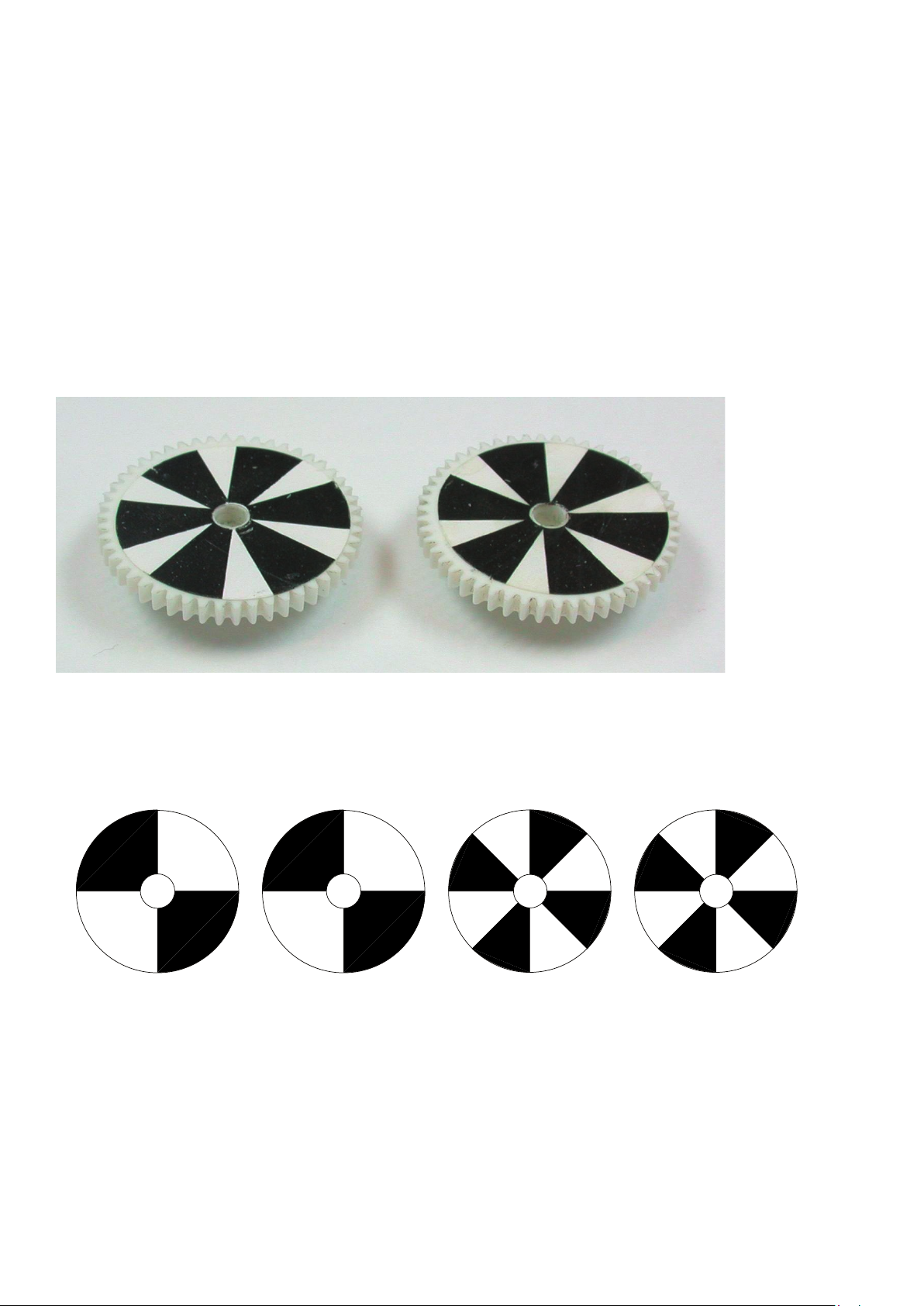
A complete set of adhesive odometer markers is supplied with this kit. Place them on to the
50/10 gear as shown in g. 2.3.
Using the sensor-markers with 6 black and white segments is
recommended for compatibility for compatibility with other ASURO’s (demo programs).
The more segments you draw, the better the cogspeed may be registrated and the better speed
control will work. However, a great number of segments reduces the difference between light and
dark (see g.2.4).
g. 2.4.: Examples for the cogwheel markers
You now have completed the mechanical preparations.
Take a short break ...
We will now continue with the electronics.
Mechanics
g. 2.3.:
RECOMMENDED
cogwheel markers
Page 9
ASURO - 9
-
Part II. Electronics
3. Soldering instructions
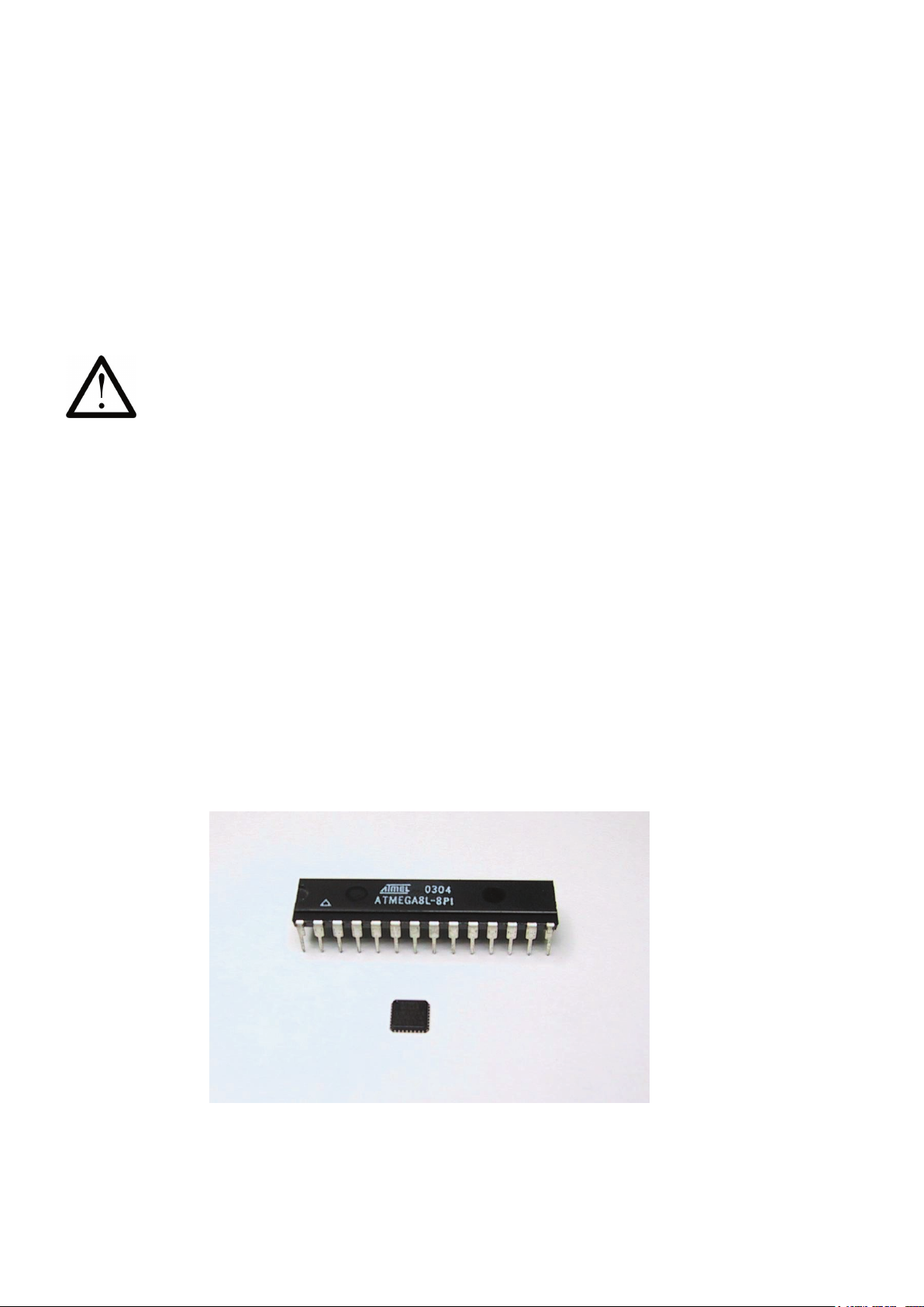
ASURO has been designed with wired parts (in contrast to the much smaller surface mounted
devices). Fig. 3.1
the wired device we have incorporated. The chip inside these devices however is the same!
Although soldering wired devices is much more comfortable and easier, especially untrained
and power supplies!!!
3.1. Tip, solder and temperature
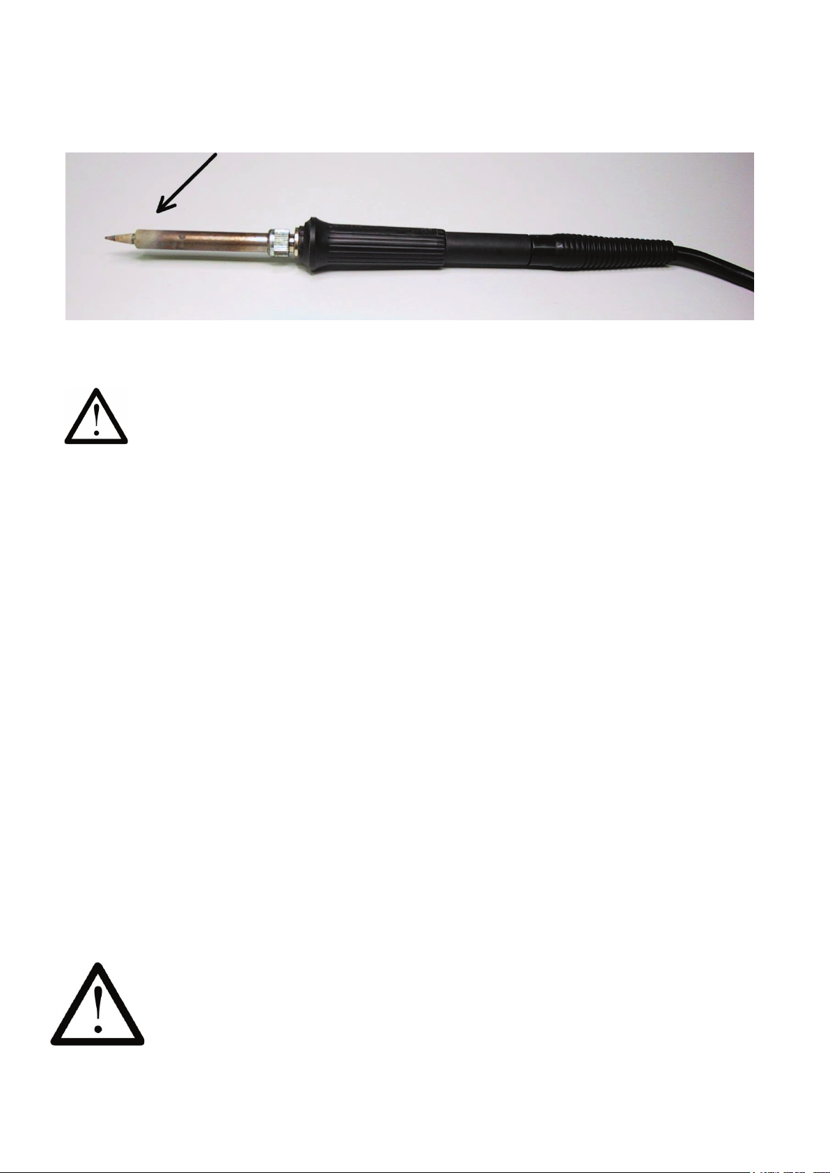
Fig. 3.2
the basics for soldering. The hot spot of the soldering equipment should
reach ca. 360ºC with lead-solder and ca. 390ºC for lead-free solder, while soldering axles may
be done at higher temperatures (420ºC). Electronics are to be soldered with a miniature tip, while
axles must be soldered with a larger tip area.
Use a slightly humid soldering sponge and apply some solder to the hot soldering tip. Shortly
before using soldering equipment, for the rst time or after a break, old solder must be removed by
wiping off soldering remains from the tip.
Do use solder for electronic work with a diameter of 0.8 or 1 mm.
Fig. 3.1.: Comparison of the largest and smallest case in which the ATmega8L chip is available.
Page 10
ASURO - 10
Avoid breathing gases or work under a cooker hood. Using solder for non-electronic use and
3.2. Preparing parts
While soldering small parts you will need some tricks and tips to reach the soldering area. When
you already have soldered before you already may have noticed that there is always one hand
short (a tool called third hand can solve a part of this problem).
Some parts (transistors, LEDs, ICs, switches, capacitors and jumper) are already prepared to t
into the PCB (printed circuit board), but diodes and resistors have to be prepared to do so.
Resistors are to be placed vertically in ASURO. To do so, one leg remains in its original position,
the other one is to be bent 180 degrees. Bending must de done at a curvature of 2.5 mm diameter
at a distance of a few millimeters from the resistor body to avoid damage to the part.
Diodes are inserted for horizontal position. To do so both legs have to be bent (eg. by pincers) at a
distance to t into the holes of the PCB.
Processor IC1 ATmega, IC3 CD4081and the IR-receiver IC2 SFH5110-36 are sensitive to
ESD (electrostatic damage). They may be damaged by simply touching or even reaching for
these parts if you have been charged with electricity (eg. by walking on a carpet).
Before handling these parts you should discharge yourself with a discharging bracelet,
connected to ground or at least by touching a grounded heater system or a metallic case of
equipment.
DANGEROUS END !
Page 11
ASURO - 11
-
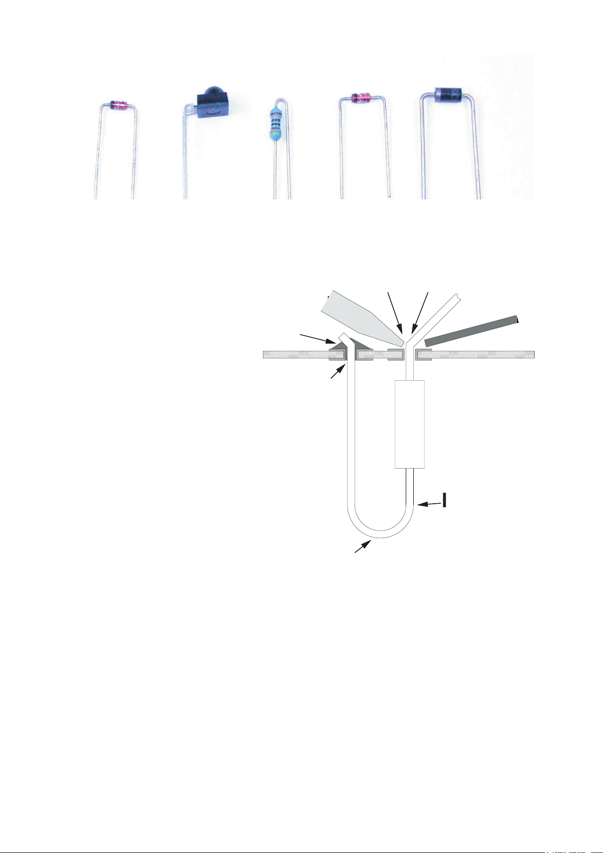
Fig. 3.3 : Parts with bended legs
3.4:
Creating a neat soldering connection
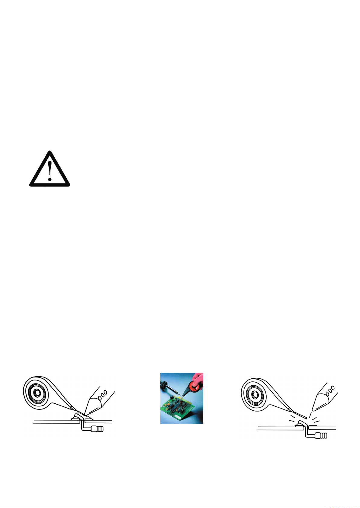
3.3. Soldering parts
After preparing the legs, parts are to be tted in the metallized holes of the printed circuit board
(PCB) and – for parts with only two or three legs – to be spread. Bending the leg at the backside
of the PCB will prevent parts from falling down. For parts with more legs – eg. the sockets for ICs
– bending two opposite legs on a diagonal line will suf ce completely.
After xing a part, apply some heat with the soldering tip to the leg and the soldering pad
simultaneously. At the same time you will have to add a small quantity of solder. While melting, the
solder will ow into the metallized hole. Add some more solder until the hole is lled completely
(see g.
3.4).
A. Part
have to be heated simultaneously
H. Bending legs to prevent parts falling
out from the PCB
I. Bend area at some distance from the
part
A
H
Page 12
ASURO - 12
Bad soldering contacts may be recognized by ball-shaped slugs of solder around a pad or a mat
surface (for lead-less solder the surface will even be extremely mat) and must be re-soldered.
To insert sockets and other parts for horizontal mounting on the PCB you may use the following
trick: First of all you just solder one leg of the part. Then you press the part down slightly, while
heating the same soldering pad (Caution: the part may become very hot). The part will now
settle to the surface of the board and remain in a xed position. You now solder all other contacts.
Finally re-solder the rst contact again with some extra solder.
After soldering a part the outstanding wires of the legs are to be cut off with a pair of pincers. Cut
the legs off closely to the PCB, while taking care not to pull or push the legs.
Be careful for sharp-edged pieces of wire ying around while cutting the legs.
Vertically mounted parts of course are not allowed to make contact to neighbors and
must be bent apart if they have been placed too close.
3.4 De-soldering
When, ocassionally, a part has landed on a spot where it does not belong then you have to
The following may be some help for you;
Add some ex to the soldering of the part which must be removed (a simple way of doing this is to
You may repeat this on the other side of the hole when there is still solder in it.
Page 13
ASURO - 13
-
4. Electronic assembly
Did you read the soldering instructions? Really? Well OK, let’s go!
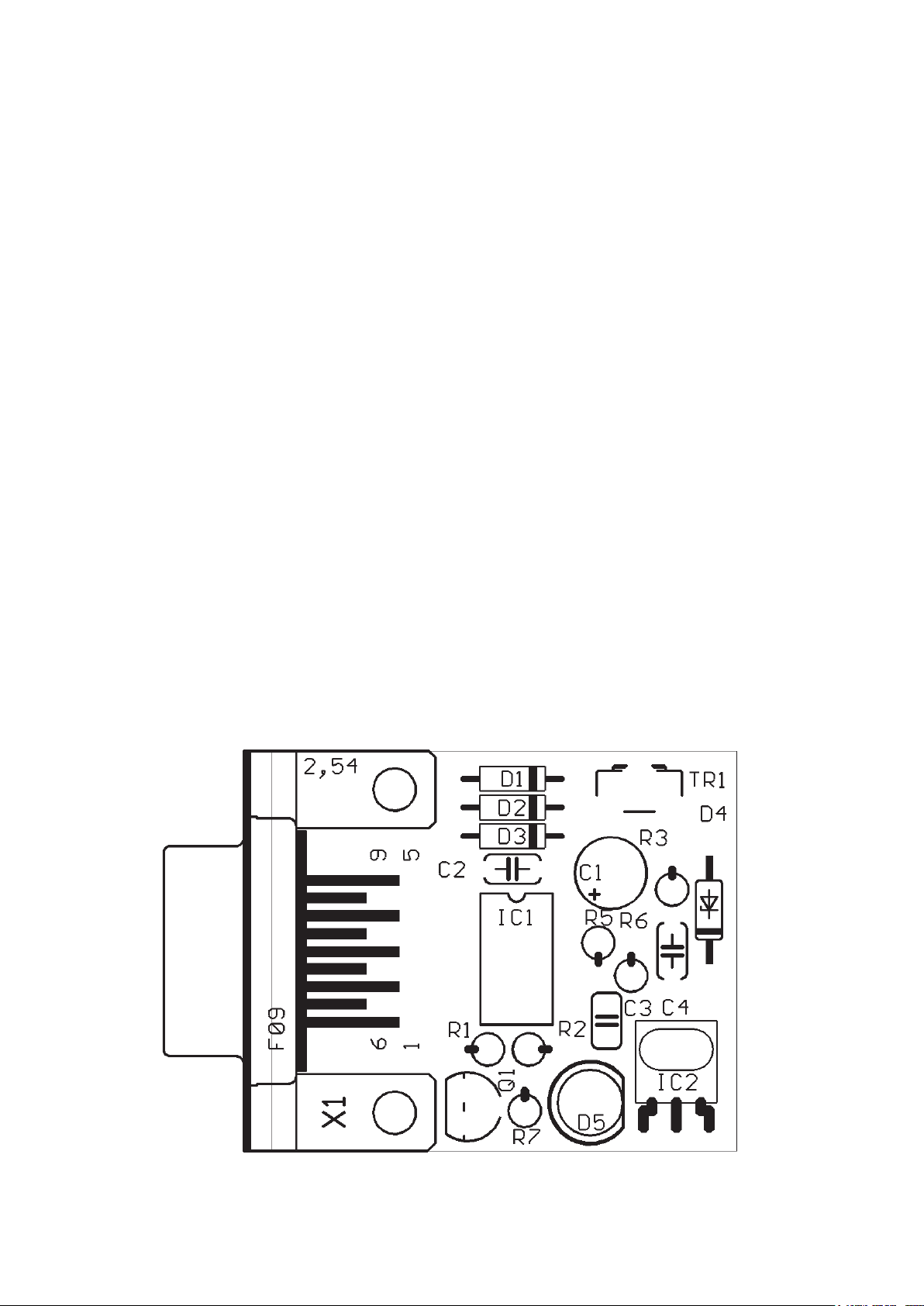
4.1. Assembling the RS232 infrared-transceiver
• IC1: Initially insert the 8-pole socket. The polarity mark of the (slightly asymmetrical) socket
must correspond to the mark in the accompanying symbol on the PCB.
• D1, D2, D3: 1N4148, pay attention to polarity! Read the imprints of the parts and take care
not to interchange with ZPD5.1 or BZX55-C5V1!
• D4: ZPD5.1 or BZX55-C5V1, pay attention to polarity! Read the imprints of the parts and
take care not to interchange with 1N4148!
• D5: SFH-415-U IR LED (Black LED) pay attention to polarity, press downwards to the PCB
• C1: 100µF at least 16 volt, pay attention to polarity!
• C2, C4: 100nF ceramic capacitor, imprint: 104
• C3: 680pF ceramic capacitor, imprint: 681
• Q1: BC547 (A,B or C) or BC548 (A,B or C)
• R1, R5: 20kΩ_ (red, black, orange, gold)
• R2: 4.7kΩ (yellow, violet, red, gold)
• R3: 470Ω (yellow, violet, black, gold)
• R6: 10kΩ (brown, black, orange, gold)
• R7: 220Ω (red, red, brown, gold)
• TR1: 10KΩ variable resistor
• IC2: SFH5110-36 Infrared receiver IC, bend the legs with appropriate tongs! Pay attention
to polarity (the curvature must be positioned to the outside)! Caution: electrostatic discharge
(ESD) and excessive soldering or heating may damage the part!
• X1: 9pol. SUB-D connector, case must be settled close to PCB. Attachment strips must be
soldered as well!
• IC1: insert the NE555P, pay attention to polarity!
Finally check the board for short circuits or polarity errors. Check the soldering quality intensively
and re-solder bad contacts.
Ready!
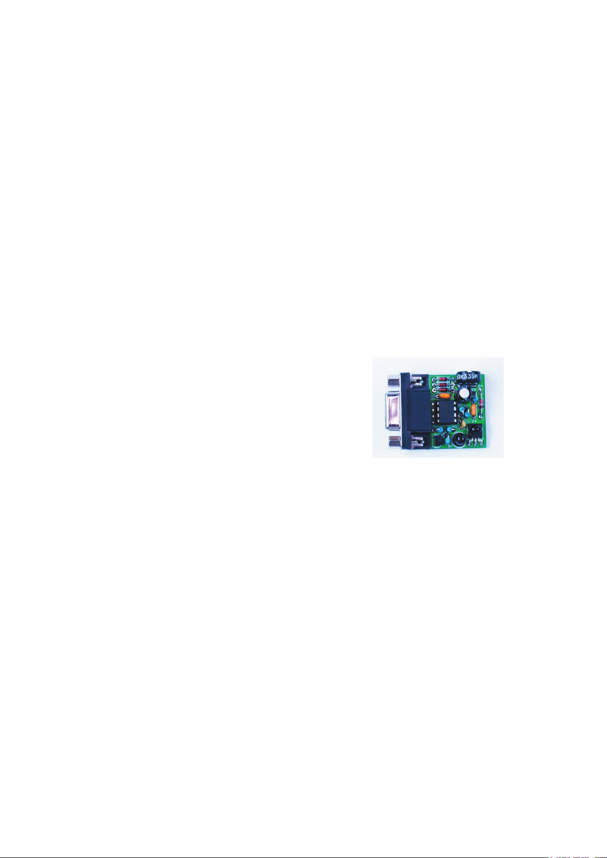
Page 14
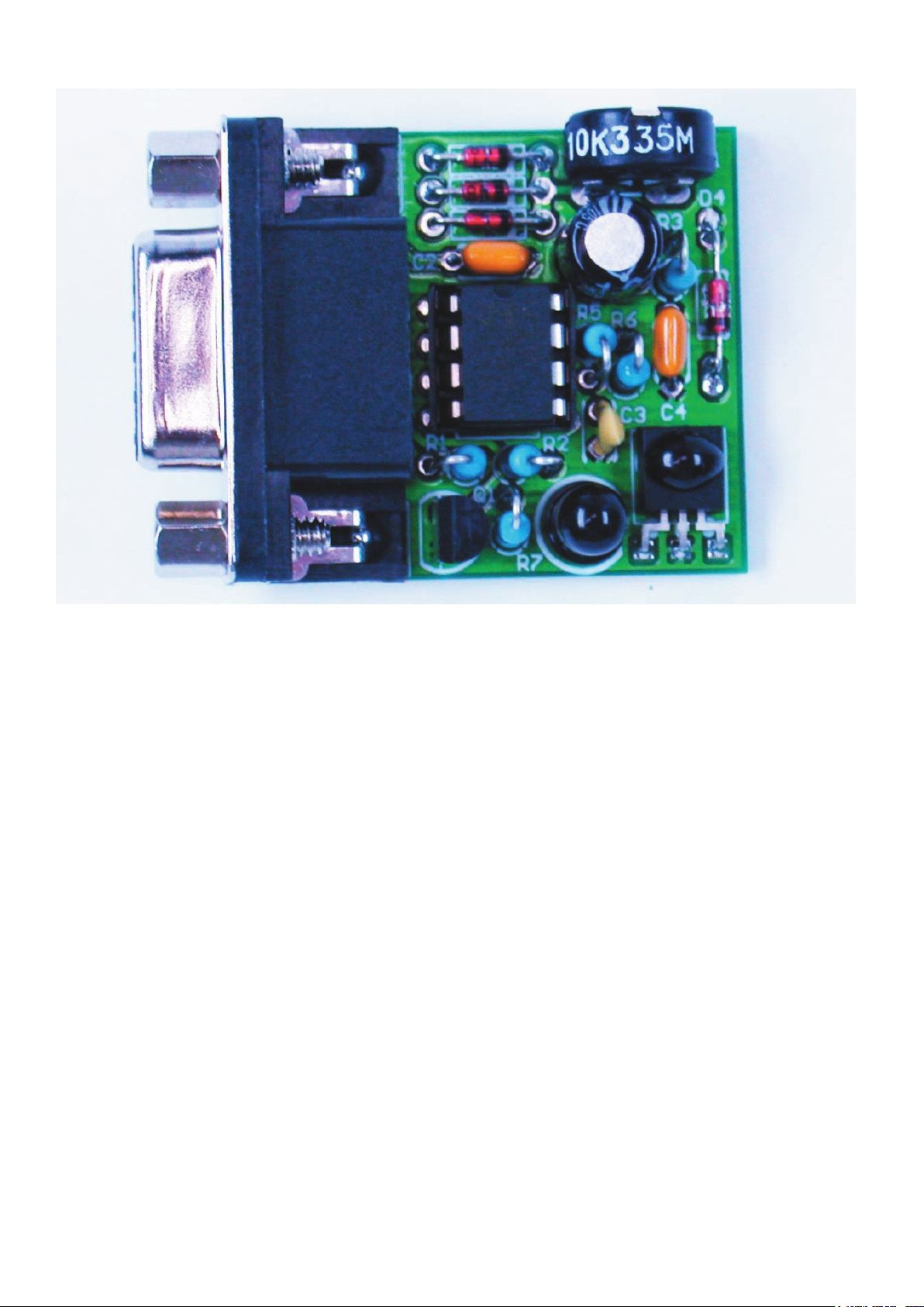
g. 4.1.: Assembled IR-Transceiver
When the RS-232-IR-transceiver is ready assembled with the parts it will look
like the above picture.
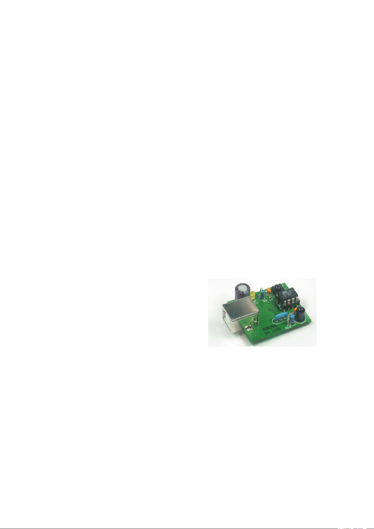
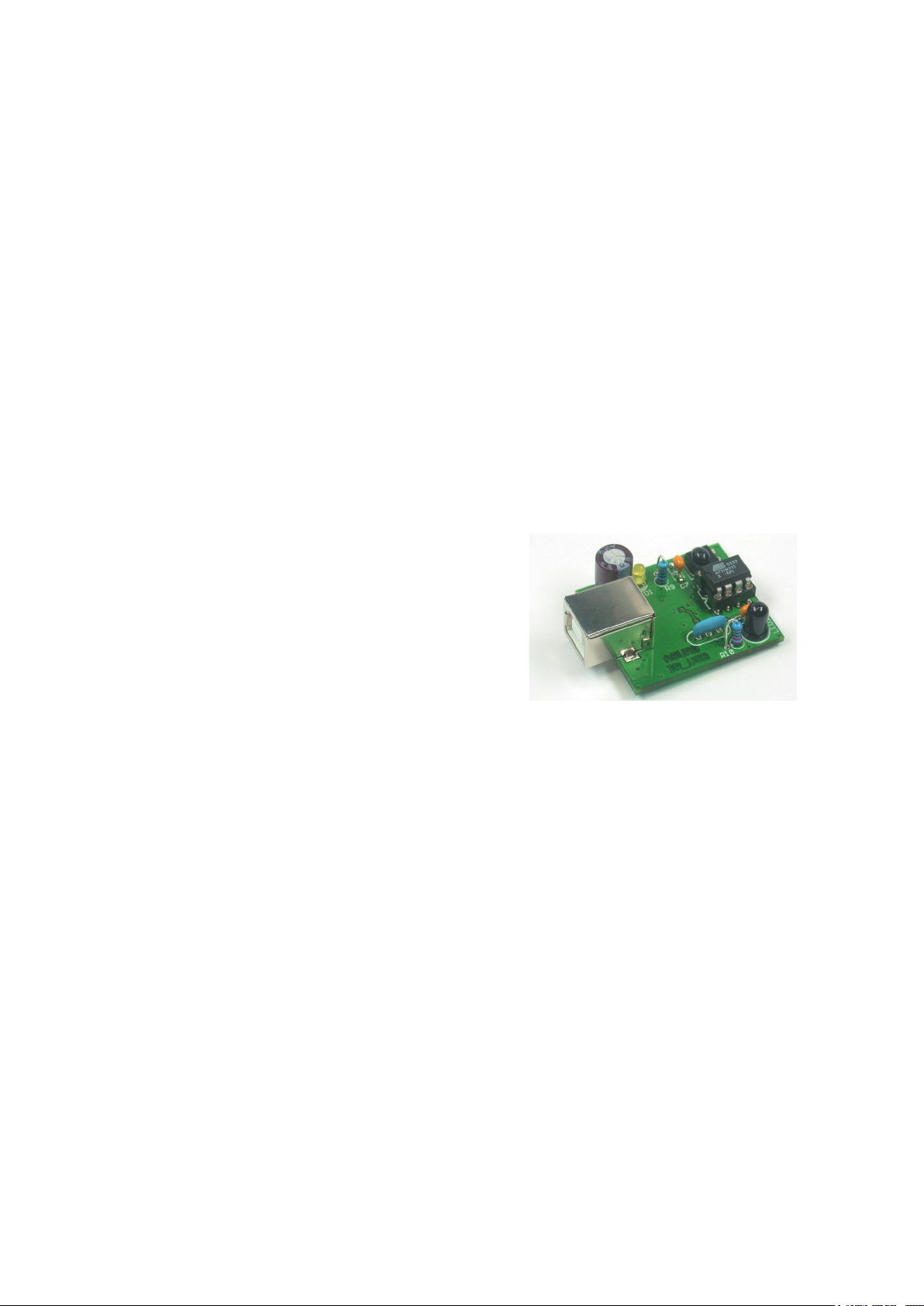
Page 15
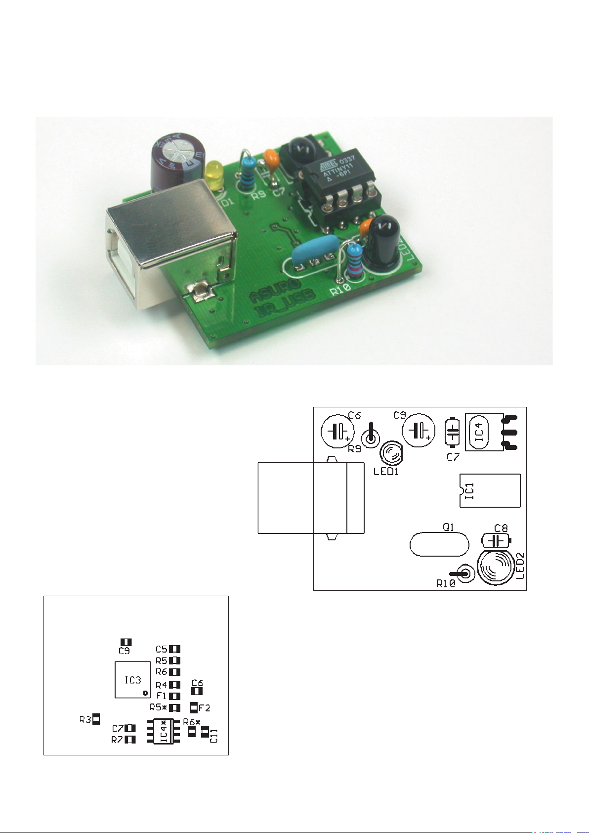
Fig. 4.2.: USB Infrared-Transceiver
Fig. 4.3.: Component side USB Infrared-Transceiver
Fig. 4.4.: Bottom side USB Infrared-Transceiver
4.2. Assembled USB IR-transceiver
Page 16
ASURO - 16
4.3. Inserting parts in the ASURO-PCB
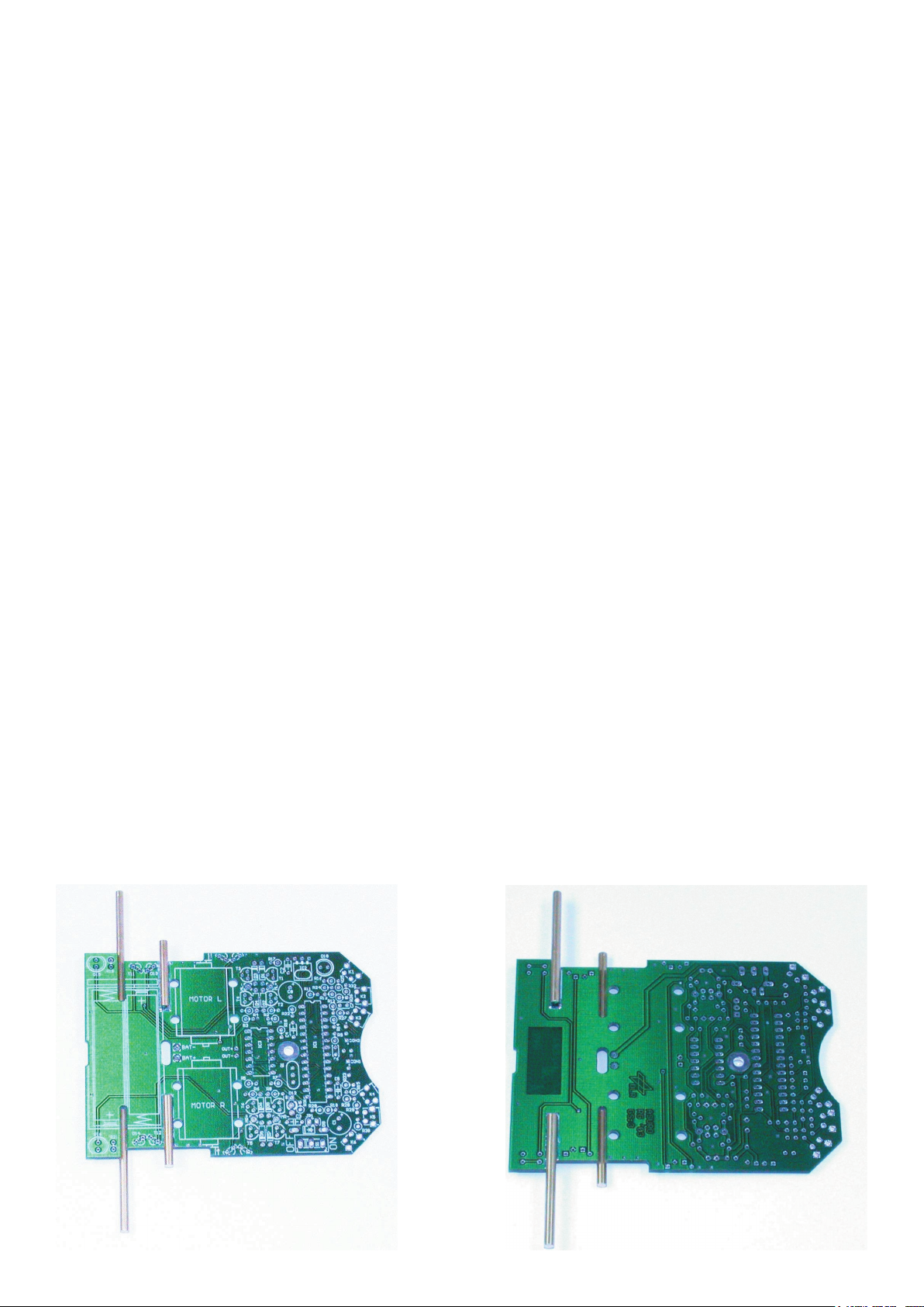
The two longer axles, which will be needed for the second gear section are to be soldered or glued
at the bottom-side of the PCB. Soldering is the best option, it hardens much faster than gluing and
you always can easily correct it afterwards when necessary.
The two shorter axles have to be attached at the upper PCB-side nearer to the middle of the
board. Before attachment, the axles must be cleaned at the soldering or glue-side (but not at the
wheel-side) with some very ne sandpaper (corning number 240 or more), in order to improve
adhesion of the solder respectively glue. If you choose soldering these parts, the following
procedure should be followed:
First of all the longer axles will be attached. Put the PCB on a table with the bottom side upward
and place the longer axle into the slide. Push it fully to the end of the slide. The axle should be
laying at at the length of the slide. Wet the soldering tip with some solder and press the tip onto
the axle. After heating the axle you must add solder at the soldering pads beside the axles. After
the soldering is nished, the soldering iron can be removed, while pressing the axle downwards
with a screwdriver until the soldering connection is cooled off completely.
Repeat the procedure with the second long axle. Turn the PCB around and repeat the procedure
with both short axles. Fig. 4.3 shows the PCB with four axles attached.
After a cooling phase the wheels may be attached to the axles. The cogwheels must t exactly
and the wheels are to rotate easily. If the wheels do not rotate easily, the axles might have been
attached erroneously and you will have to repeat the procedure. In case some solder fractions
should be attached to the surface of the axles in the wheel area, they must be removed by
sandpaper or with a ne le.
If the wheels rotate easily, they may be removed and be put aside in order to place the electronic
parts onto the PCB.
Fig. 4.3.:
ASURO-PCB with attached axles
Page 17
ASURO - 17
-
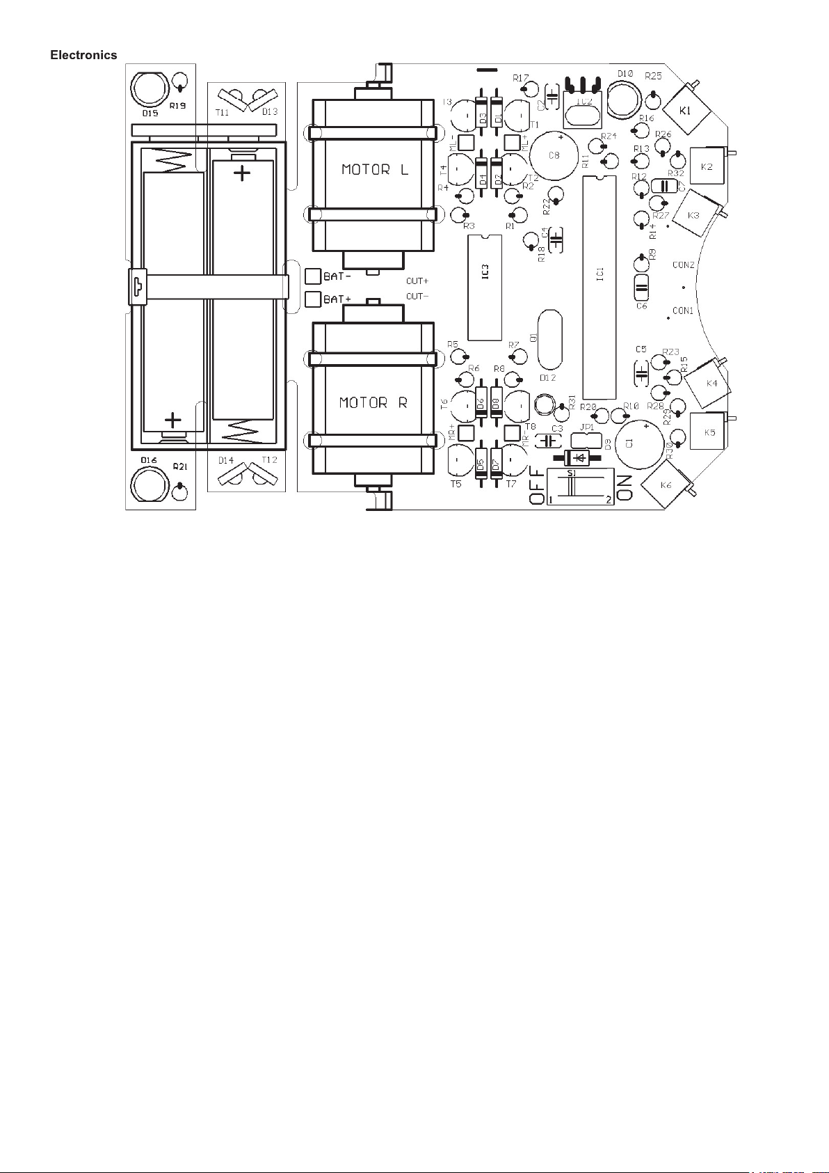
The following inserting sequence may be used as a guideline:
• IC1: at rst insert only the socket (either one Dual in line 28 pole-socket or two Dual in line
14 pole-sockets). Pay attention to polarity! A slight asymmetry is a mark for polarity in the
socket and in the symbols on the PCB!
• IC3: Again insert only the socket (Dual in line 14 pole-socket). Pay attention to polarity! A
slight asymmetry is a mark for polarity in the socket and in the symbols on the PCB!
• K1, K2, K3, K4, K5, K6: Sensor-switches, which must be mounted at to the PCB surface!
• Q1; Resonator 8MHz
• D1, D2, D3, D4, D5, D6, D7, D8: Diode 1N4148; Pay attention to polarity!
• D9: 1N4001; Pay attention to polarity!
• JP1: Jumper; Short pins will be soldered, do not yet apply the jumper connector element!
• D12: Dual colored LED, 3 mm diameter, three legs ; Pay attention to polarity! (polarity may
differ from part to part, however: the shortest leg must be inserted into the square soldering
pad)!
• C2, C3, C4, C5: 100nF Ceramic; Imprinted: 104
• C6, C7: 4,7nF Ceramic; Imprinted: 472
Fig. 4.2: Inserting parts view of upper-side to the main ASURO-PCB
Page 18

ASURO - 18
• T1, T3, T5, T7: BC327-40 or BC328-40
• T2, T4, T6, T8: BC337-40 or BC338-40
• R1, R2, R3, R4, R5, R6, R7, R8, R19, R21, R24: 1kΩ (brown, black, red, gold)
• R9, R16: 220Ω (red, red, brown, gold)
• R10, R17, R22, R31: 470Ω (yellow, violet, brown, gold)
• R11: 100Ω (brown, black, brown, gold)
• R12: 12kΩ (brown, red, orange, gold)
• R13: 10kΩ (brown, black, orange, gold)
• R14, R15: 20kΩ (red, black, orange, gold)
• R18, R20: 4,7kΩ (yellow, violet, red, gold)
• R23: 1MΩ (brown, black, green, gold)
• R25, R26, R32: 2kΩ (red, black, black, brown, brown)
• R27: 8,2kΩ (grey, red, black, brown, brown)
• R28: 16kΩ (brown, blue, black, red, brown)
• R29: 33kΩ (orange, orange, black, red, brown)
• R30: 68kΩ (blue, grey, black, red, brown)
• C1, C8: Elco 220_F 10V or higher values; Pay attention to polarity!
• IC2: SFH5110-36 Infrared-receiver-IC, bend the legs with long-nose pliers!
Pay attention to polarity (the side with dome-shaped curvature must be positioned to the
outside)! Caution: electrostatic discharge (ESD) and excessive soldering or heating may
damage the part!
• D10: SFH 415-U IR-LED 5mm; black case; Pay attention to polarity! Case must be settled
close to PCB.
• T11, T12: LPT80A, Phototransistor, colorless case;
Case must be settled close to PCB; Pay attention to polarity!
• D13, D14: IRL80A, IR-LED, rosy case;
Case must be settled close to PCB; Pay attention to polarity!
• D15, D16: LED 5 mm red, rosy respectively red case. Pay attention to polarity
(short leg must be inserted at the mark)!
• S1: On/Off-Switch
Page 19
ASURO - 19
-
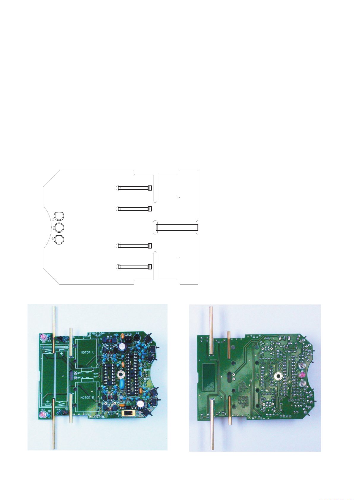
Three more parts will be needed (which will be used to follow a line), but they will be placed at the
bottom side of the PCB and have to soldered from the upper side
4.5
• T9, T10: SFH300, Phototransistor 5 mm; Pay attention to polarity! These components have
to be placed at some distance from the PCB.
• D11: LED 5 mm red, red or reddisch case; Pay attention to polarity! (short leg must be
inserted at the mark)!
Fig. 4.6 gives an overview of the PCB with all parts inserted up to this phase in top view and in
bottom view.
That’s all! We will need no other electronic components.
In the next steps we will place electromechanical components and mechanical parts.
Fig. 4.6.: ASURO top side and bottom side, completely equipped
Fig. 4.5.:
Inserting parts at the bottom side of
the ASURO-PCB
Page 20
ASURO - 20
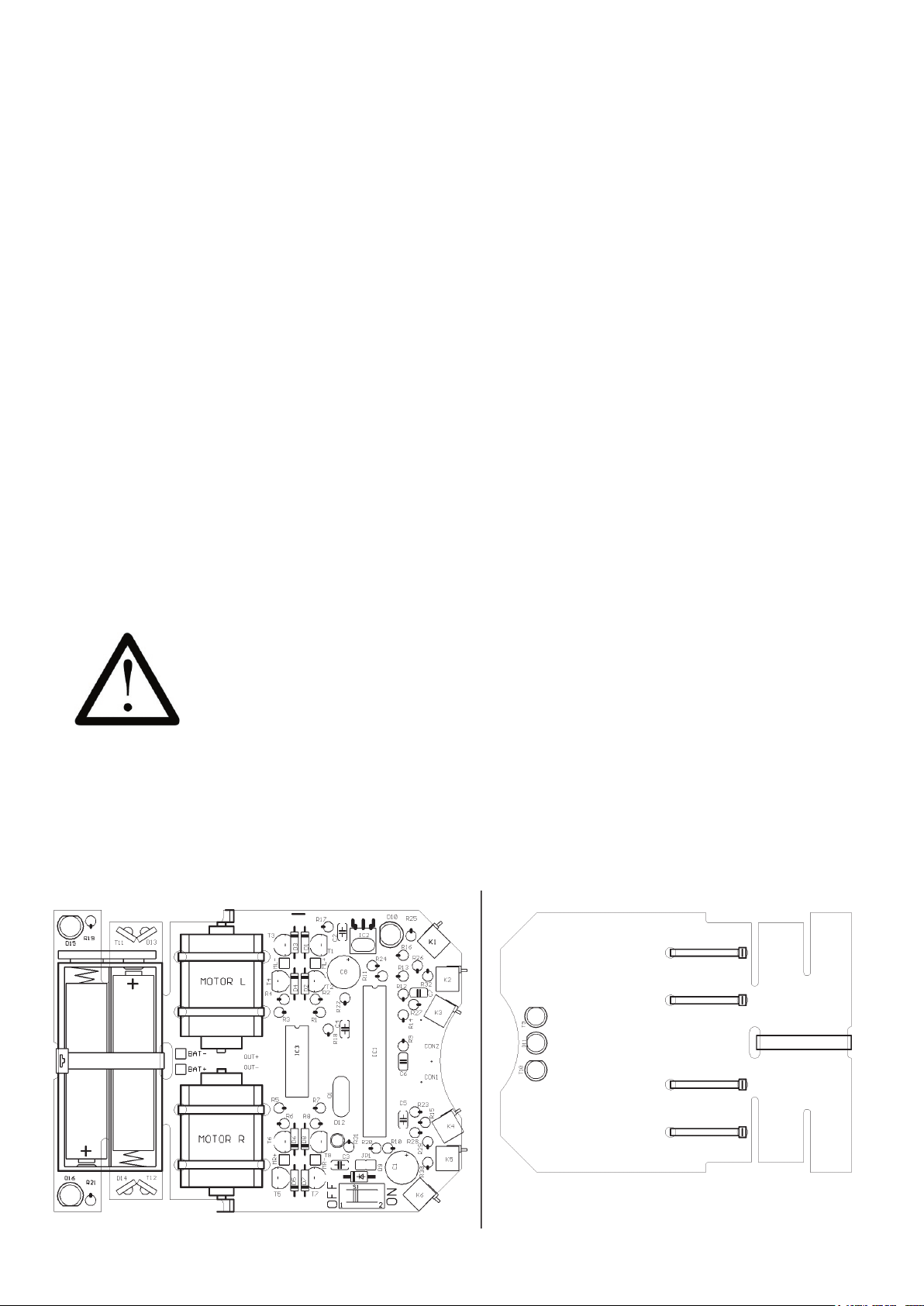
4.4. Attachment of the motors
After completing the insertion of the parts on the ASURO-PCB, we must supply the motors with
cabling and attach these parts temporarely for some tests.
To supply electrical energy to the motor, we need 70 mm red and black wire for each terminal.
These four wires for two motors have to be stripped at both ends for around 4 mm. The ends
of the wires have to be twisted and pre-soldered with some solder. Any surplus parts of solder
attached at the end of the wires may be cut off with a diagonal cutter. By soldering, we attach the
red wire to the motor terminal, marked with a dot or a plus-sign. The black wire will be attached to
the other terminal.
The wiring for the motors may be twisted (not necessary, but it will diminish sensitivity for
electromagnetic disturbances and it looks much better...).
The red wire of the motor on the left side must be soldered into the “ML+”-port, the black wire into
the “ML-”-port, the red wire of the motor on the right side must be soldered into the “MR+”-port, the
black wire into the “MR-”-port.
Next we have to attach the motors temporarily to the PCB by cable-tiers. Use two holes to insert
the supplied cable-tiers. In the rst phase it will be suf cient to attach the two inner cable-tiers only.
4.5. Power supply
If ASURO is to be equipped and operated with batteries, you must open Jumper JP1
at any rate!
BAT+”, and the black wire
BAT-“
terminal. Check and be sure the ON/OFF-switch is in the OFF-position. Place the four power
cells, correctly polarised, into the
the
Page 21
ASURO - 21
-
5. Preparation for operation
After completing the assembly we will start moving the robot. But rst we will have to nd and
eliminate the errors we could have made in the previous phase, without destroying any parts.
5.1. RS232-Infrared-Transceiver
The following operational check is limited to the RS232-Infrared-Tranceiver (Fig. 4.8).
First of all the IR-Transceiver must be checked, as it will be needed for the next step: the selftest
of the system. For this test connect the IR-Transceiver to a free serial interface of your PC with the
supplied 9-pole serial extension cable and start the Windows terminal program “Hyperterminal” (or
for a Linux-system eg. “Minicom”). Normally you will nd this program in Windows in the category
Addons --> Communication --> Hyperterminal. If the program is not available, you can install it
from the Windows-CD.
After starting the Hyperterminal program you will be asked to de ne a name for the connection.
You may choose ASURO or any other symbol. In the next window you choose “connect by”
and the COM-interface by which the transceiver has been connected in the previous step.
Then press “OK” and choose the following settings:
• Bits pro Second: 2400
• Databits: 8
• Parity: none
• Stopbits: 1
• Flowcontrol: none
Press “OK” again for con rmation
Hold the IR-Transceiver at the distance of 10 cm over a white sheet of paper. The component side
must be directed towards the paper sheet.
Press a few keys at your computer terminal.
The terminal programm normally should display the key-symbols. The IR-Transceiver transmits
the key-symbols by IR-Diode (D5), the transmitted signal re ects at the paper surface and is send
back to receiver-IC (IC2), from which it is being returned to the computer. If no symbols or wrong
symbols are being displayed you may carefully turn the trimmer between its extreme left and right
positions. Use a miniature screwdriver and strike a few keys at each position of the trimmer until
the correct symbols are displayed.
If you do not have any success in this procedure, we do have a problem with the circuit, which
should be solved (see paragraph 6.1).
Just to be sure you should remove the IR-Transceiver after this test and hit a few keys. This time
the display is now expected to show no symbols any more.
Page 22
ASURO - 22
5.2. USB-Infrared-Tranceiver
This operation is only for the USDB IR-Transceiver.
WARNING! The USB IR-Transceiver does not have a housing and therefore it is very sensitive
for electrostatic discharge. Before you use it, discharge your body by touching a metal computer
housing or other earth point. An other option is to build the USB IR-Transceiver in a transparant
housing for further protection.
The following operational check is limited to the USB Infrared-Tranceiver.
First of all the IR-Transceiver must be checked, as it will be needed for the next step: the selftest
of the system. For this test connect the IR-Transceiver to a free USB port of your PC by a
USB extension cable.
Now a message will apear “NEW HARWARE WAS FOUND”;
AREXX ASURO USB-IR-TRANSCEIVER
Now you can install the USB driver from the ASURO CD. When the driver is not detected
automatically you can select it from the CD manualy from CD\windows\USB Driver, (Administrator
rigths are necesary for this operation). When the driver is installed you can approach the USB
transceiver like a normal serial port.
After starting the Hyperterminal program you will be asked to de ne a name for the connection.
You may choose ASURO USB or any other symbol. In the next window you choose “connect by”
and the COM-interface by which the transceiver has been connected in the previous step.
Then press “OK” and choose the following settings:
• Bits pro Second: 2400
• Databits: 8
• Parity: none
• Stopbits: 1
• Flowcontrol: none
Press “OK” again for con rmation
Hold the IR-Transceiver at the distance of 10 cm over a white sheet of paper. The component side
must be directed towards the paper sheet.
Press a few keys at your computer terminal.
The terminal programm normally should display the key-symbols. The IR-Transceiver transmits
the key-symbols by IR-Diode (D5), the transmitted signal re ects at the paper surface and is send
back to receiver-IC (IC2), from which it is being returned to the computer. If no symbols or wrong
symbols are being displayed you may carefully turn the trimmer between its extreme left and right
positions. Use a miniature screwdriver and strike a few keys at each position of the trimmer until
the correct symbols are displayed.
If you do not have any success in this procedure, we do have a problem with the circuit, which
should be solved (see paragraph 6.1).
Page 23
ASURO - 23
-
The following operational check is limited to the USB Infrared-Tranceiver and LINUX software.
First of all the IR-Transceiver must be checked, as it will be needed for the next step: the selftest
of the system. For this test connect the IR-Transceiver to a free USB port of your PC by a
USB extension cable. A short beep will con rm that the transceiver was detected by the LINUX
software. To be sure please check in the proc-declaration if the following message is displayed.
foo@bar:/>cat /proc/tty/driver/usb-serial
There is also an entry with the following (‘0’ in our example can also be ‘1’ or ‘2’ etc.):
folowing settings:
• Bits pro Second: 2400
• Databits: 8
• Parity: none
• Stopbits: 1
• Flowcontrol: none
Press “OK” again for con rmation
ttyUSB0 (of course again you need the root.ricgts).
Hold the IR-Transceiver at the distance of 10 cm over a white sheet of paper. The component side
must be directed towards the paper sheet.
Press a few keys at your computer terminal.
The terminal programm normally should display the key-symbols. The IR-Transceiver transmits
the key-symbols by IR-Diode (D5), the transmitted signal re ects at the paper surface and is send
back to receiver-IC (IC2), from which it is being returned to the computer. If no symbols or wrong
symbols are being displayed you may carefully turn the trimmer between its extreme left and right
positions. Use a miniature screwdriver and strike a few keys at each position of the trimmer until
the correct symbols are displayed.
Page 24
ASURO - 24
5.3. ASURO operation
Caution: The processor (IC1) is not to be inserted yet!
Now be careful and turn the main switch ON. Both back-LEDs (D15, D16) should be glowing dimly.
If they do not glow dimly, pleasy switch off the system immediately and continue reading in chapter
6.3
IC1 (Processor) and IC3
(AND Gate) (see g.
5.1).
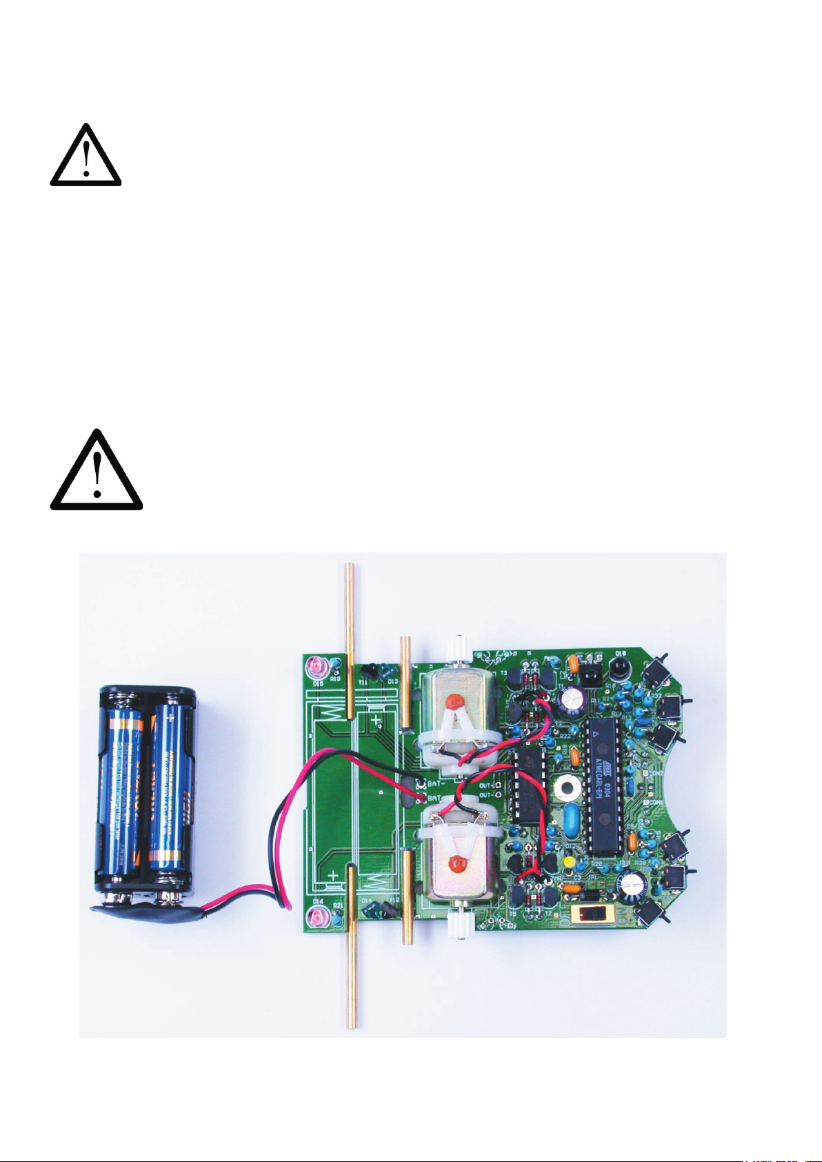
Sometimes the legs of an IC have to be bent carefully in order to insert all legs into the contact
holes of the socket. This can be done easily if you take the IC and press the side with all legs on
the row parallel on the surface of a at table.
Processor IC1 ATmega8 and Gate IC3 CD4081both are electrostatically sensitive
devices. They might be destroyed by touching them, if you do have charged yourself
electrostatically, which may easily occur by walking over a non-conductive oor.
Before working with these parts, it is a good idea to wear a grounding bracelet or at least to
touch a metallic case of grounded equipment or a heating radiator.
g.5.1.: ASURO after installing the ICs
Page 25
ASURO - 25
-
Now insert the Jumper (J1) for recheargable devices. The polarity marks of the ICs must align with
the marks of the sockets and the marks on the PCB. The processor has been designed to do a
selftest and it will check all components on power up. Just to avoid any dif culties in this phase,
you are advised to read the next chapter completely before switching power ON and then return
to this chapter. At this point we start testing. Switch the power ON and keep your eyes xed to the
ASURO from now on.
5.3.1. Display-elements
The Status-LED (D12) shortly lights orange and the “Back-LEDs” (D15, D16) also glow, but these
glow only dimly. If one of these signs does not show, switch OFF immediatedly and start error
checking and removal (see paragraph 6.3.3). You just have seen the boot-sequence of ASURO. In
the next phase all display-elements will be checked subsequently at a distance of 3 seconds and
in the following order:
• Status-LED (D12) green
• Status-LED (D12) red
• Front-LED (D11) at the bottomside of the ASURO
• Back-LED (D15) left
• Back-LED (D16) right
• All display-elements together
If an error occurs, switch OFF ASURO immediately and start error checking and removal (see
paragraph 6.4.), as all display elements play an important role for all following tests.
5.3.2. Phototransistors (T9, T10)
After nishing the display tests the Status-LED (D12) should light in green, indicating clearly the
Phototransistors at the bottomside of ASURO and responsible for line tracing, are now being
tested for about 10 seconds.
While lighting the Phototransistors (T9, T10), the accompanying Back-LEDs (D15, D16) will be
turned on and dim as soon as the light is switched off (right phototransistor(T10)
right back-LED
(D16); left phototransistor(T9)
left back-LED (D15)). Everything is OK, if the back-LEDs do not
go out completely after removing the light and continue glowing dimly. Even in case an error is
found, the selftest may be continued and the error removal may be postponed.
When the program Hyperterminal (Windows) or minicom (Linux) is active
and there is a visible contact between ASURO and the Infrared-Transceiver
it is possible to follow the self test on you computer screen.
Page 26
ASURO - 26
5.3.3. Switches
ASURO is immobile and all displays are dark. That is a good omen! Now we are ready to check
the switches for about 15 seconds. Just hit the switches, to see if something happens.
The result should be:
K1
Status-LED (D12) is switched on green
K2
Status-LED (D12) is switched on red
K3
Front-LED at the bottom side is switched on
K4
Back-LED left (D15)
K5
Back-LED right (D16)
K6
Motor left starts running (If the motor does not start running, the selftest may be
continued. The motors will be checked separately later and an error in this segment
may be removed in the tests described in chapter 6.8).
Pressing several switches will initiate an equivalent combination of signals. On errors the selftest
may be continued. Error removal may be postponed.
5.3.4. Odometer
Now the linetracer-LED (D11) starts lighting. This signal indicates the beginning of the next test
(15 seconds), in which both odometers (each consisting of a LED and a phototransistor) are being
checked. Holding a white sheet of paper in front of the sensors will result in lighting the statusLED. First of all hold a sheet of paper in front of the left sensor (T11).
Status-LED (D12) lights
green. Then hold a sheet of paper in front of the right sensor (T12)
Status-LED (D12) lights red.
Removing the sheet will result in switching off the status-LED. If the on/off-thresholds are active
on the left and on the right side, the odometers are OK. If an error occurs, the selftest may be
continued anyway. Error removal may be postponed.
5.3.5. The engine
Both back-LEDs (D15, D16) are switched on, indicating the last test, which lasts ca. 15 seconds.
The motors will be checked intensively. The left motor is started in forward direction from zero
speed to maximum speed and back to zero again. Then the direction will be reversed and speed
is accelerated from zero to maximum and back again to zero. The motor on the right side will be
checked the same way. After checking the single motors both will be checked simultaneously.
Again we will repeat the remarks only once more: If an error occurs, the selftest may be continued
anyway. Error removal may be postponed.
5.3.6. IR interface
If the status-LED lights intermittently yellow, the last test has been started (ca. 15 seconds), in
which the IR interface transmits and receives data. In order to receive these data, the previously
assembled IR-Tranceiver has to be connected to the PC and a terminal program, eg. the Windows
terminal program “Hyperterminal” may be used for this purpose. The con guration will be the same
as at the testprocedure for the IR-Tranceiver.
At the receipt of symbols, ASURO will answer with a symbol next following in the alphabet. If
within a xed time limit no symbols have been received, ASURO transmits a ‘T’. Any sent symbol
will switch on the RED status-LED parallel to the green status-LED, which results in an orange
ashing colour.
Page 27
ASURO - 27
-
If an optical connection between ASURO and the Infrared-Transceiver has been arranged (which
requires a maximal distance of ca. 50 cm), the terminal program will show up a symbol ‘T’ regularly
or alternatively the button you may have activated at the PC’s keyboard (as it has been transmitted
by the transceiver), followed by the symbol next in the alphabet, eg.:
Key “e” is activated
terminal program reports “ef”
Key “j” is activated
terminal program reports “jk”
Key “3” is activated
terminal program reports “34”
In case of errors see chapter 6.9.
5.3.7. ready ?
If an error has occurred, switch the system OFF and remove the batteries. Trace and eliminate the
error by methods in chapter 6 . Repeat the selftest to see if no component has been damaged.
Only a completed and errorfree selftest will guarantee the ASURO hardware is OK and that any
other errors will have to be found in the software.
If you have to check the hardware after you have installed other programs in ASURO, the selftest
program “SelfTest.hex” has to be reloaded and programmed from CD.
Page 28

ASURO - 28
6. Error tracing
6.1. Failure of the RS232-IR-transceiver
6.1.1. Activated key and displayed symbol do not match
Calibrate Trimmer TR1 until activated key and displayed symbol do match.
6.1.2. The terminal program does not display any symbol
Has the timer-IC (IC1) been inserted and has it been inserted correctly polarized (the mark
must point to the three diodes) ? Take any infrared remote control of a HIFI- or video-equipment
(videorecorder, TV, etc) and point it to the IR-transceiver, pressing a few keys. If the terminal
program displays irregular symbols, the receiver (IC2, R3, C4, D4, T1) is operating. All other parts
have to be checked.
6.1.3. Still not working
Check all parts for correct polarisation and correct value (see g.
4.1). Check soldering
connections for short circuits and bad soldering. Has a soldering pad been disrupted ?
If all checks have been made without results, the bad part has to be traced with the help of the
schematic (see Appendix B) and an adequate measurement device (multimeter or oscilloscope).
(In most cases one of the components IC1, IC2, Q1, D4 may have been damaged).
6.2. USB-infrared-tranceiver does not work
An other option is to install a new kernel
6.3. Back-LEDs (D15,D16) do not glow at startup!
6.3.1. None of both back-LEDs is glowing
Please look very carefully in a darkened room. If no light can be seen, check the following steps:
- Have 4 batteries been inserted, are the batteries fresh or have they been charged anew?
- Did you connect the battery-cable correctly ? (red to Bat+ and black to Bat-)
- Has Diode D9 (1N4001) been inserted with correct polarity?
- Did you use the correct value for R22? 470Ω (yellow, violet, brown, gold)
- Also check for R18, R19, R20, R21:
4,7KΩ (yellow, violet, red, gold)
1KΩ (brown, black, red, gold)
Page 29

ASURO - 29
-
6.3.2. Only one of both back-LEDs is glowing
Did you insert the diodes (rose- or red-colored), D13 (left) ,D14 (right), and the phototransistors
(transparent or black case) T11 (left), T12 (right) at the correct position and with the correct
polarisation?
Check the value for resistors R18, R19 (left) and R20, R21 (right)?
4,7KΩ (yellow, violet, red, gold)
1KΩ (brown, black, red, gold)
Have these parts been inserted at the correct position? (check the imprint on the PCB!).
6.3.3. Status-LED (D12) is not activated bicolored after startup
Status-LED is not activated at all -> see 6.4!
Status-LED ickers. Battery voltage is too low. Replace batteries.
If the batteries are fresh, check resistors R12 and R13.
12KΩ (brown,red,black,red,brown)
10KΩ (brown,black,black,red,brown)
6.4. A display element does not work
Has the processor been inserted correctly ? (Polarity!)
6.4.1. Status-LED D12 does not work
Check polarisation of LED D12.
Check resistors R10, R31
470Ω (yellow, violet, brown, gold)
A simple check may be done the following way: remove the processor (IC1) and connect by wire
Pin7 (VCC) and Pin14 (Status-LED will be activated green) respectively Pin4 (Status-LED will be
activated red). If this test is succesful, (1) either the processor may be defective, or (2) a track of
the PCB may be broken / interrupted.
6.4.2. Front-LED D11 does not work
Check polarisation of LED D11.
Check resistor R9
220Ω (red, red, brown, gold)
A simple check may be done the following way: remove the processor (IC1) and connect by wire
Pin7 (VCC) and Pin12 (Front-LED will be activated red). If this test is succesful, (1) either the
processor may be defective, or (2) a track of the PCB may be broken / interrupted.
Page 30

ASURO - 30
6.4.3. Left back-LED D15 does not work
Check polarisation of LED D15.
Check resistors R19, R18.
1KΩ (brown, black, red, gold)
4,7KΩ (yellow, violet, red, gold)
A simple check may be done the following way: remove the processor (IC1) and connect by wire
Pin7 (VCC) and Pin24 (left back-LED will be activated red). If this test is succesful, (1) either the
processor may be defective, or (2) a track of the PCB may be broken / interrupted.
6.4.4. Right back-LED D16 does not work
Check polarisation of LED D16.
Check resistors R21, R20.
1kΩ (brown, black, red, gold)
4,7kΩ (yellow, violet, red, gold)
A simple check may be done the following way: remove the processor (IC1) and connect by wire
Pin7 (VCC) and Pin23 (right back-LED will be activated red). If this test is succesful, (1) either the
processor may be defective, or (2) a track of the PCB may be broken / interrupted.
6.5. Linetracer sensor (T9, T10) does not work
Check polarisation of T9, T10.
Check resistors R14, R15.
20KΩ (red, black, orange, gold)
Check, if R15, R23 and R28 have not been inserted in a wrong position!
Check the sensor signal at Pin25 respectively Pin26 with a multimeter after removing the
processor (dark ≈ 0V, light ≈ VCC).
6.6. A switch does not work
6.6.1. Obviously a combination of switches has been activated
Check R12 and R13
12KΩ, (brown,red,black,red,brown)
10KΩ, (brown,black,black,red,brown)
Check R24, R25, R26, R27, R28, R29, R30, R32 as well!
1KΩ (brown, black, black, brown, brown)
2KΩ (red, black, black, brown, brown)
8,2KΩ (grey, red, black, brown, brown)
16KΩ (brown, blue, black, red , brown)
33KΩ (orange, orange, black, red, brown)
68KΩ (blue, grey, black, red, brown)
2KΩ (red, black, black, brown, brown)
Page 31

ASURO - 31
-
6.6.2. The display reacts as if switches have been interchanged
Resistors to the switches have been interchanged
Check R24, R25, R26, R27, R28, R29, R30, R32 as well!
1KΩ (brown, black, black, brown, brown)
2KΩ (red, black, black, brown, brown)
8,2KΩ (grey, red, black, brown, brown)
16KΩ (brown, blue, black, red , brown)
33KΩ (orange, orange, black, red, brown)
68KΩ (blue, grey, black, red, brown)
6.6.3. Things still do not work well
Check R23, R24. Check R12, R13 and check C7 as well!
1MΩ (brown , black, green, gold)
1KΩ (brown, black, black, brown, brown)
12KΩ, (brown, red, black, red, brown)
10KΩ, (brown, black, black, red, brown)
220µF/10V
6.7. The re ected light sensor (the odometer) does not work
6.7.1. None of the re ected light sensors (odometer) is working
Check resistor R22!
470Ω (yellow, violet, brown, orange)
Check rotation of D13 and D14. D13 and D14 are rose- or grey-colored bipoled components with a
small spot at one side. The spot must point to the outside of the PCB.
6.7.2. The left re ected light sensor (odometer) does not work
Check resistor R18!
4,7KΩ (yellow, violet, red, gold)
Check rotation of T11, which is a transparent or black bipoled component with a small spot at one
side. The spot must point to the outside of the PCB.
6.7.3. The right re ected light sensor (odometer) does not work
Check resistor R20!
4,7KΩ (yellow, violet, red, gold)
Check rotation of T12, which is a transparent or black bipoled component with a small spot at one
side. The spot must point to the outside of the PCB.
You may check the sensor signal at Pin24 respectively Pin23 after removing the processor.
(dark ≈ VCC, light ≈ 0V)
Page 32

ASURO - 32
6.8. One motor does not move
6.8.1. Both motors do not move
Check polarity and position of IC3.
6.8.2. The left motor does not move or only in one direction
In this case the complete motor bridge, consisting of transistors T1, T2, T3, T4 (did you insert the
correct transistors at the correct positions?), the diodes D1, D2, D3, D4 (polarity!) and resistors
R1, R2, R3, R4.
BC327-40 or BC328-40, BC337-40 or BC338-40, BC327-40 or BC328-40, BC337-40 or
BC338-40
1KΩ (brown , black, red, gold)
6.8.2. The right motor does not move or only in one direction
In this case the complete motor bridge, consisting of transistors T5, T6, T7, T8 (did you insert the
correct transistors at the correct positions?), the diodes D5, D6, D7, D8 (polarity!) and resistors
R5, R6, R7, R8
BC327-40 or BC328-40, BC337-40 or BC338-40, BC327-40 or BC328-40, BC337-40 or
BC338-40
1KΩ (brown , black, red, gold)
6.8.4. One motor turns in the reversed direction
Check the cables, which connect the motor to the system. These connections should be
interchanged.
6.9. IR-interface
6.9.1. ASURO does not send symbols
Check polarity of IR-Diode D10.
Check resistor R16 220Ω (red, red, brown, gold)
6.9.2. ASURO does not receive symbols
You will need a line of sight between IR-Transceiver and ASURO (at a distance of max. 50 cm)
and the IR-Transceiver must be checked and OK (see chapter
6.1).
Check position and polarity of C2.
Check resistor R17 and C2.
220Ω (red,red, brown, gold)
100nF (imprint 104)
If you have not found the error yet, please remind the soldering of IC2. This component is sensitive
to overheating and may have been damaged while soldering. In this case replace the component
by a new IC (SFH 5110-36). When the transfer of data between PC and ASURO is malfunctioning
again and again, re-adjust trimmer TR1 in the transceiver.
Page 33
ASURO - 33
-
6.9.3. Things still do not work well
Check polarity of C8.
220µF/ at least 10V
If transfer of data between PC and ASURO is malfunctioning again and again, re-adjust trimmer
TR1 in the transceiver.
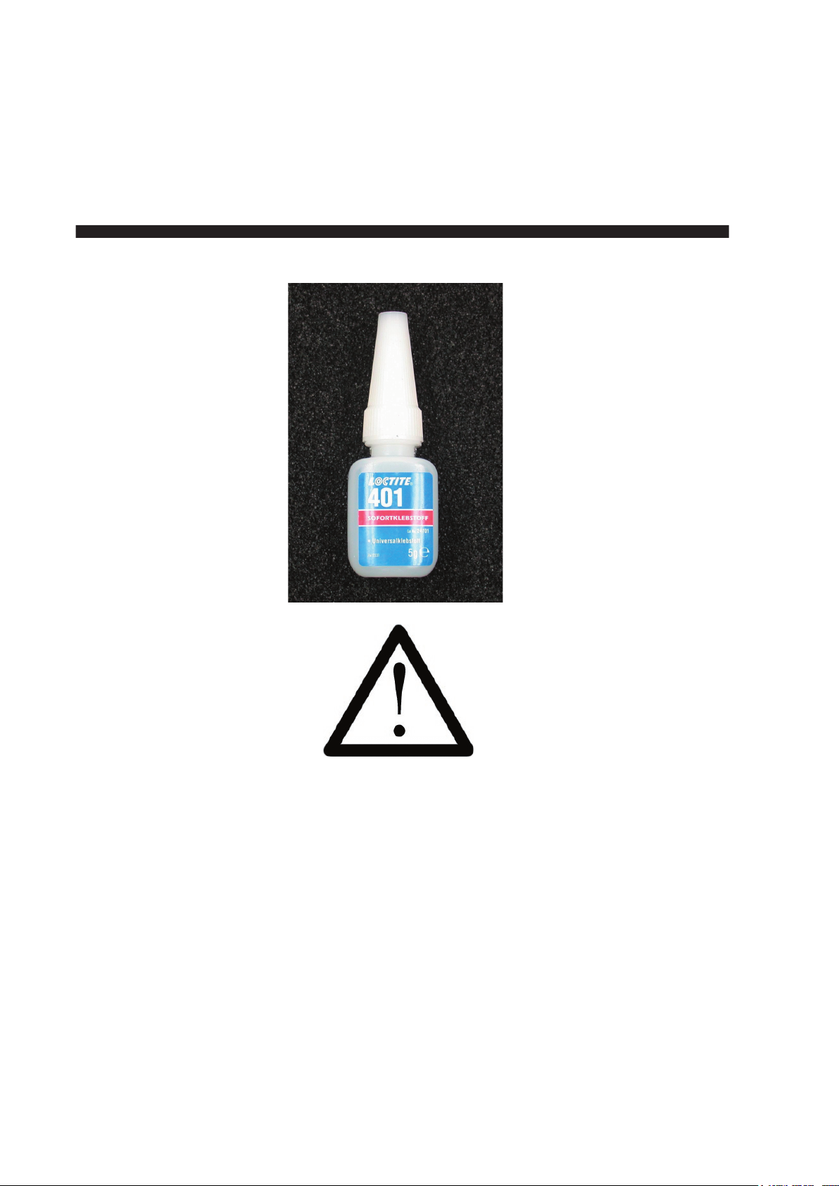
Instant and bicomponent glues are suspected to cause irritant and allergic reactions at skin
exposure. Any exposure to these materials must be avoided. Vinyl gloves may protect your hands.
If protection fails, clean body parts intensively and immediatedly with soap and water! Instant glues
originally have been developed for chirurgy, which may be noticed if your ngers are xed together
within seconds. If your ngers really are glued together by instant glue, you may loosen this xture
with warm water, soap and some patience. Be extremely careful not to touch your lips or eyelids
with glue! Suppress all re exes to wipe your face or your eyes while working with glues!
Page 34
ASURO - 34
7. Final adjustments
Grease the axles slightly. Place the cogwheels with its ne black and white markings onto the
short axles. The tires combined with the cogwheels are now placed onto the long axles and
secured by a locking ring. Move the motor, which has been xed temporarely, carefully until it has
been adjusted properly, the cogwheels t together properly and the transmission system runs
smoothly.
(Run the selftest completely to see if the motors in the transmission are working well).
If the position of the motor has been checked, keep the system tightly xed while you put a small
amount of instant glue between motor and PCB. Please remind the instant glue may take a few
seconds to stir. After xture with instant glue the cable ties are applied at the outside of the PCB.
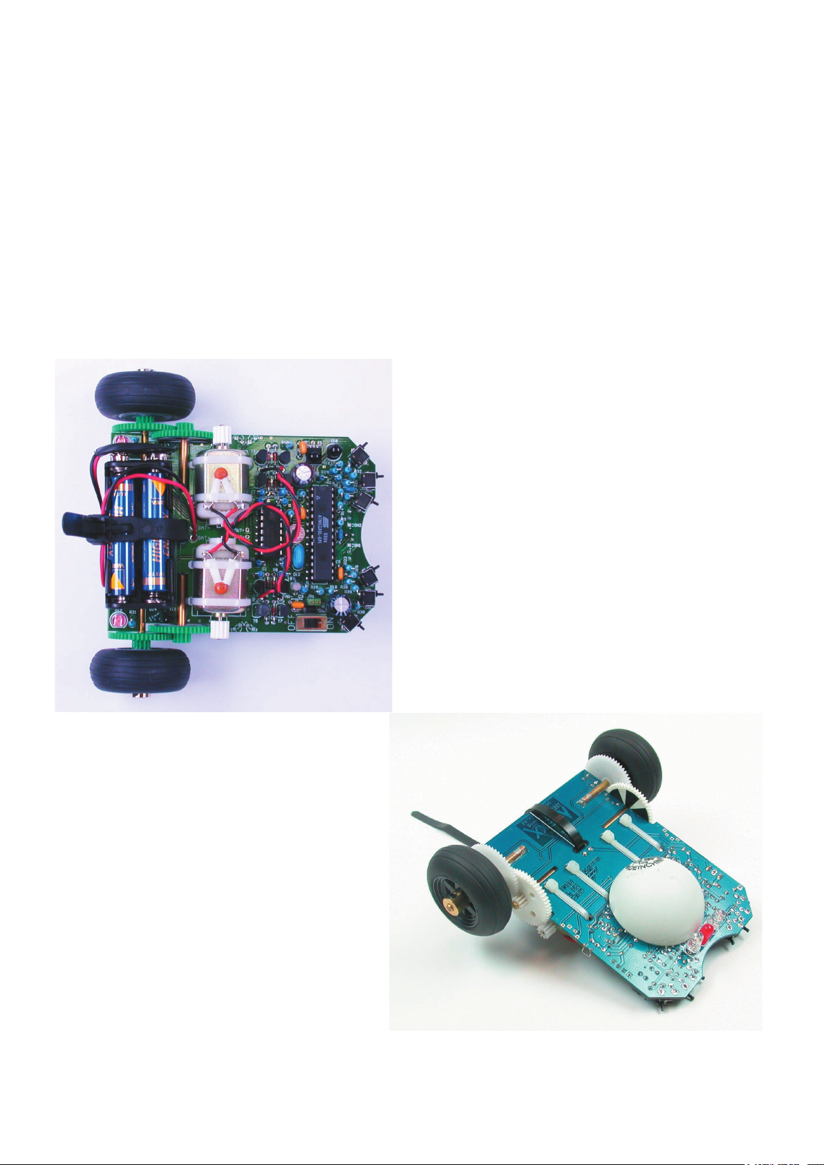
The halved table-tennis ball is to be glued with instant glue as well to the bottomside of the PCB
at two opposite positions, directly behind the linetracer-components (see g.
7.1). Please remind
again: the instant glue may take a few seconds to stir.
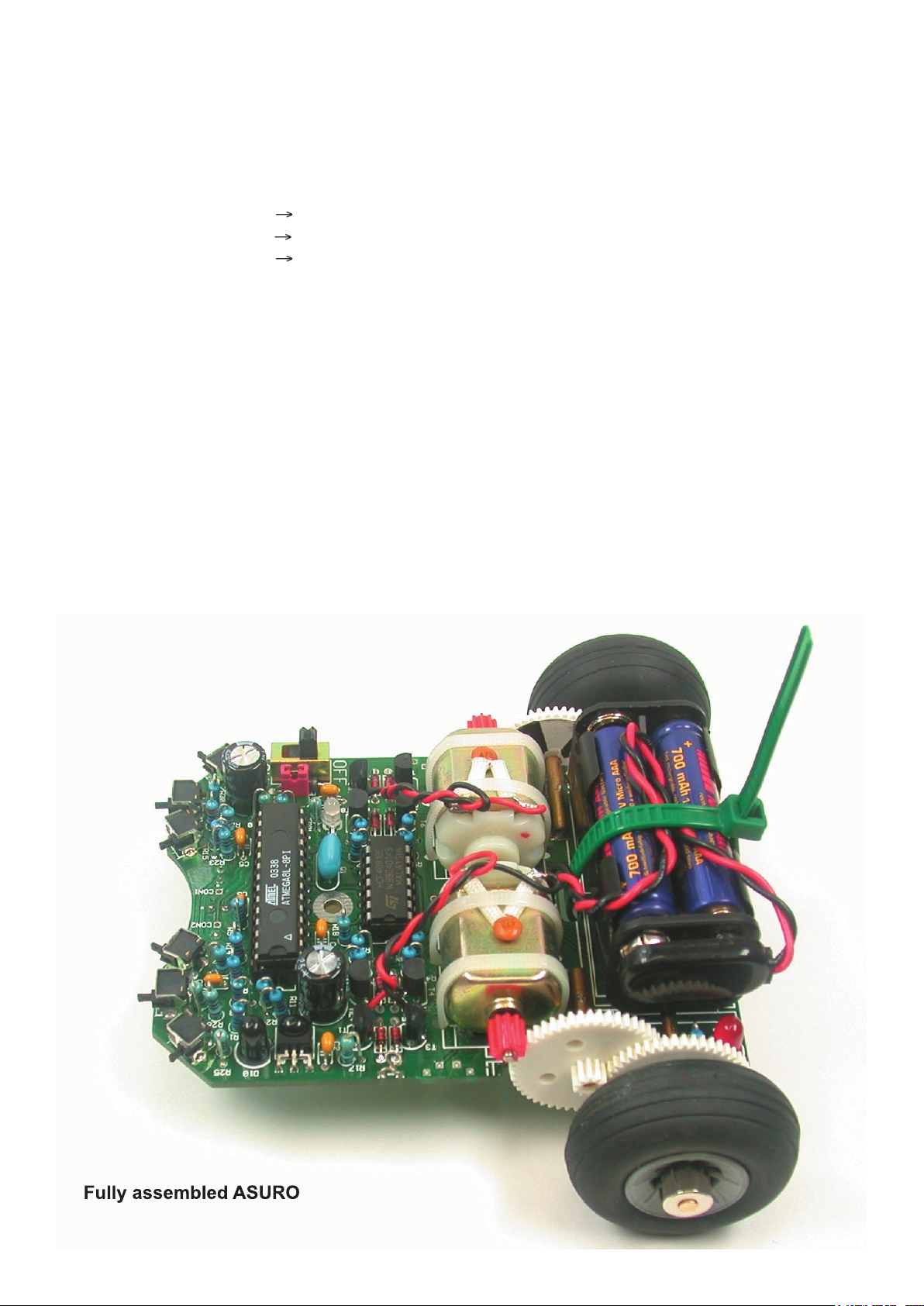
Fig 7.1.: ASURO completely assembled
Page 35
ASURO - 35
-
PART III. Software
8. Software installation and initial steps
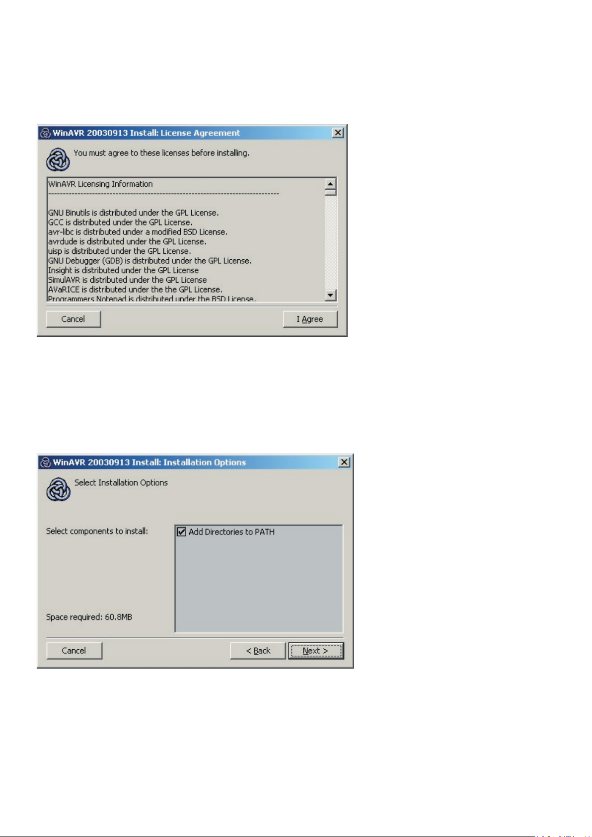
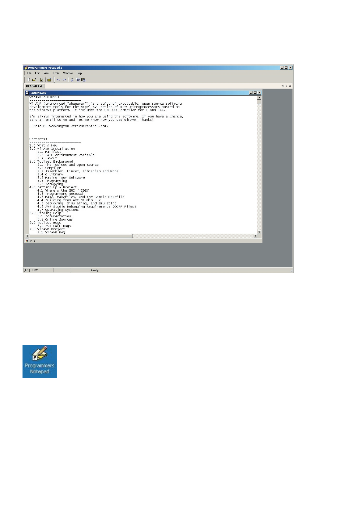
A program editor (Programmers Notepad 2, PN2) and a Compiler (WinAVR) will be
An example program(s) will be copied from CDRom to your hard disk.
We will create, in program editor (PN2), a menu input for Make and Clean les.
the computer and start up as administrator!
When nothing happens try to open the CD with windows exporer.
Page 36
ASURO - 36
Software
This screen appears:
Page 37
ASURO - 37
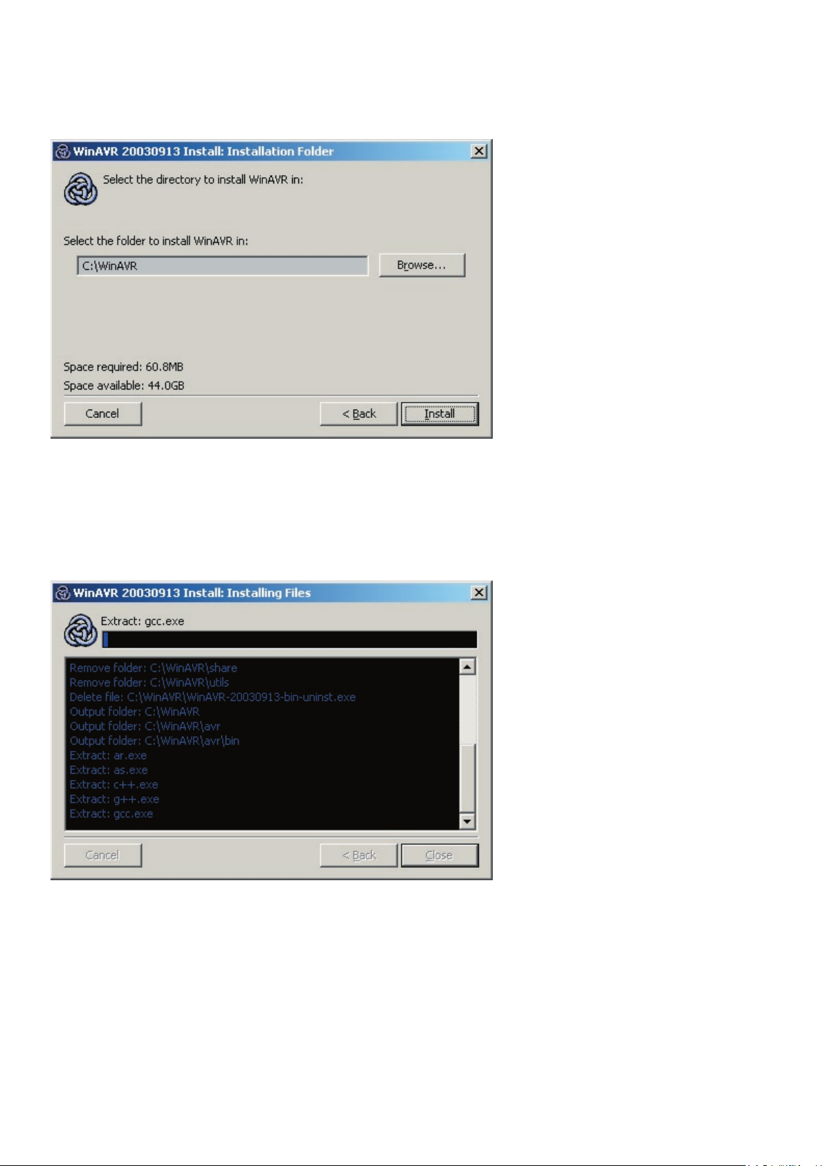
-
Software
The next screen appears:
Wait…
Page 38
ASURO - 38
The program editor and the compiler are installed now.
Software
Page 39
ASURO - 39
-
Software
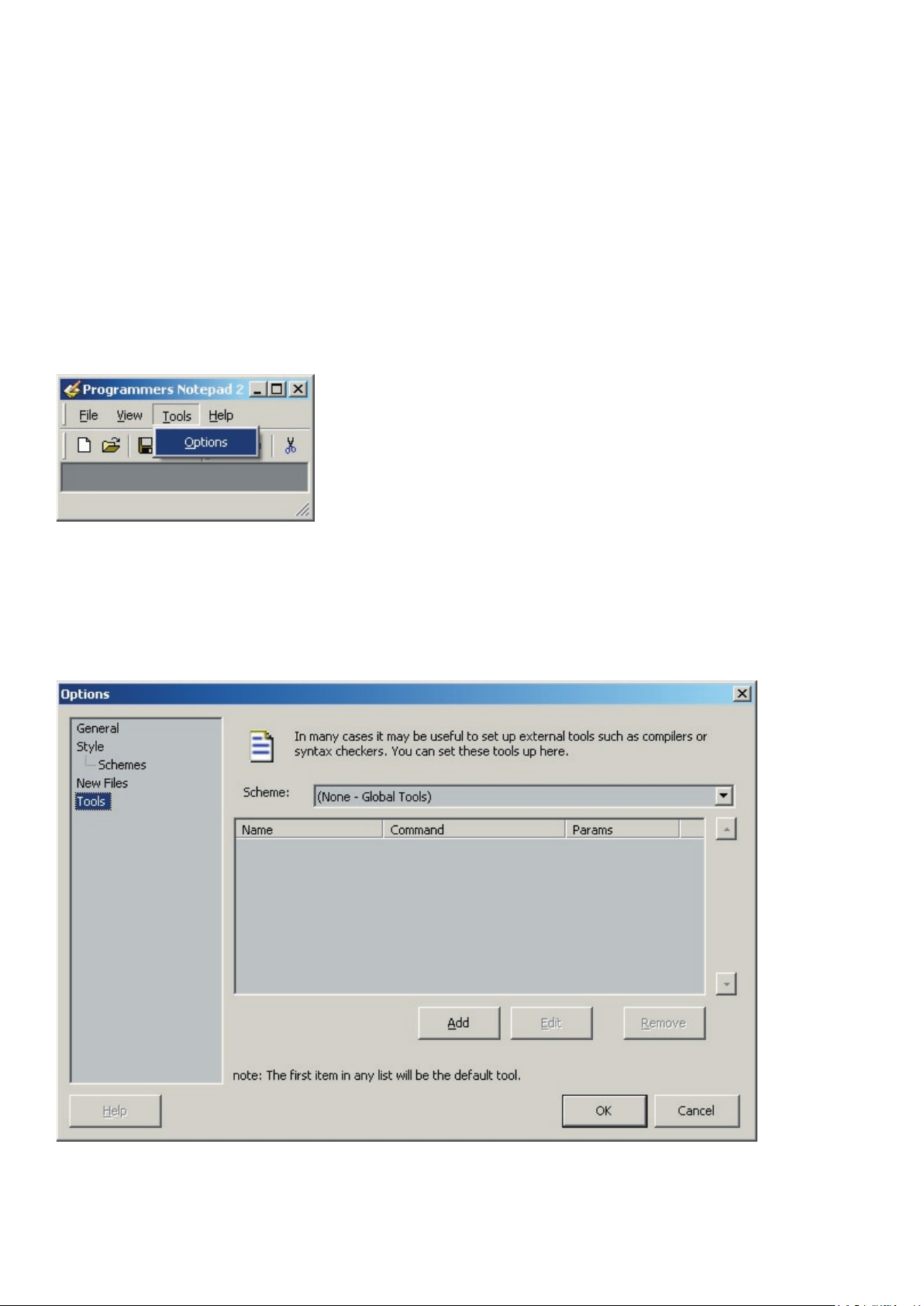
this: ‘C:\ASURO_src’).
When the data source is secured, click with the right mouse button on the le, go to properties and
The options-screen appears.
Page 40
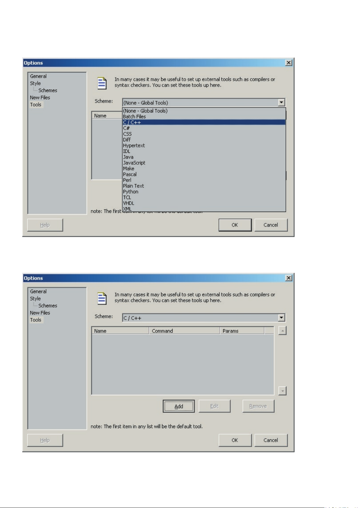
ASURO - 40
Software
Page 41
ASURO - 41
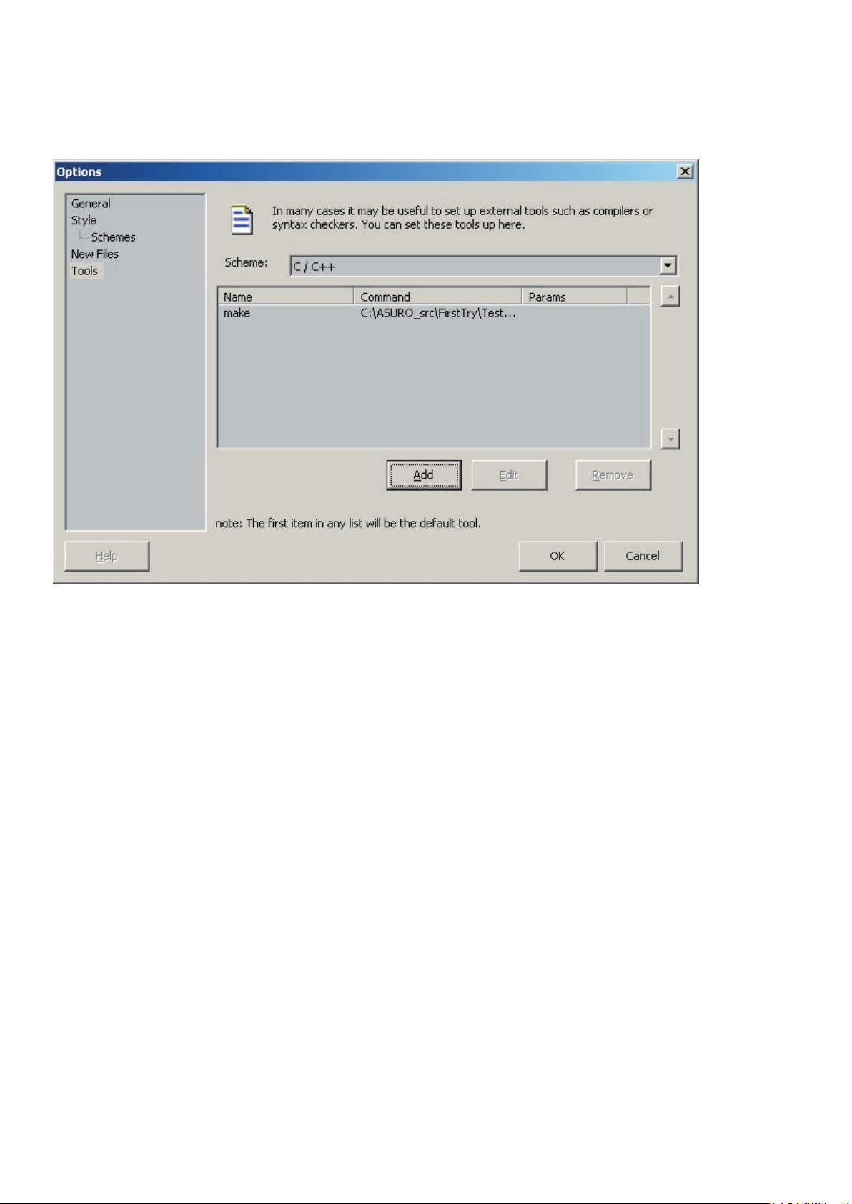
-
Software
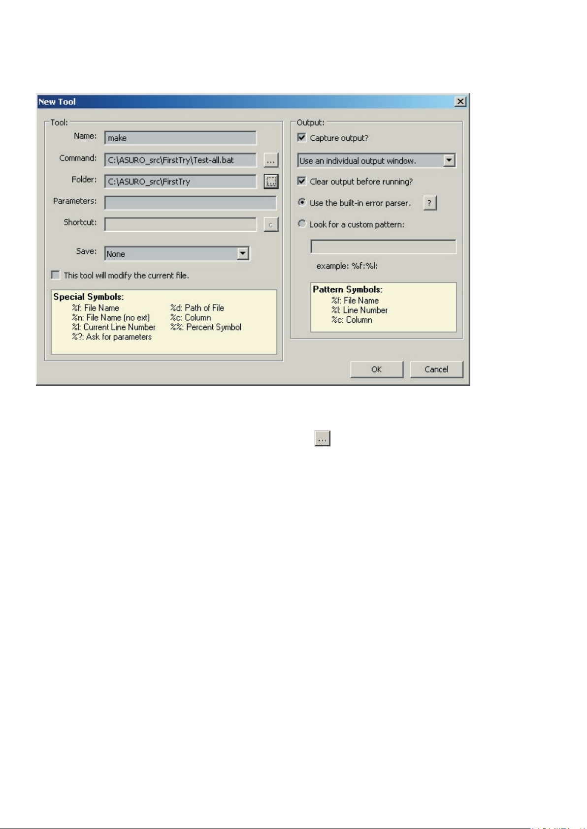
The window ‘New Tool’ appears.
Type the following or select it with the Browse-button
:
A new PN2-tool with the name “make” is now available in the tools main menu.
Page 42
ASURO - 42
Software
Page 43
ASURO - 43
-
Software
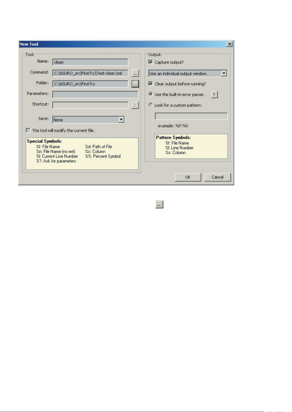
The window ‘New Tool’ appears;
Type the folowing or select it with the Browse-button
:
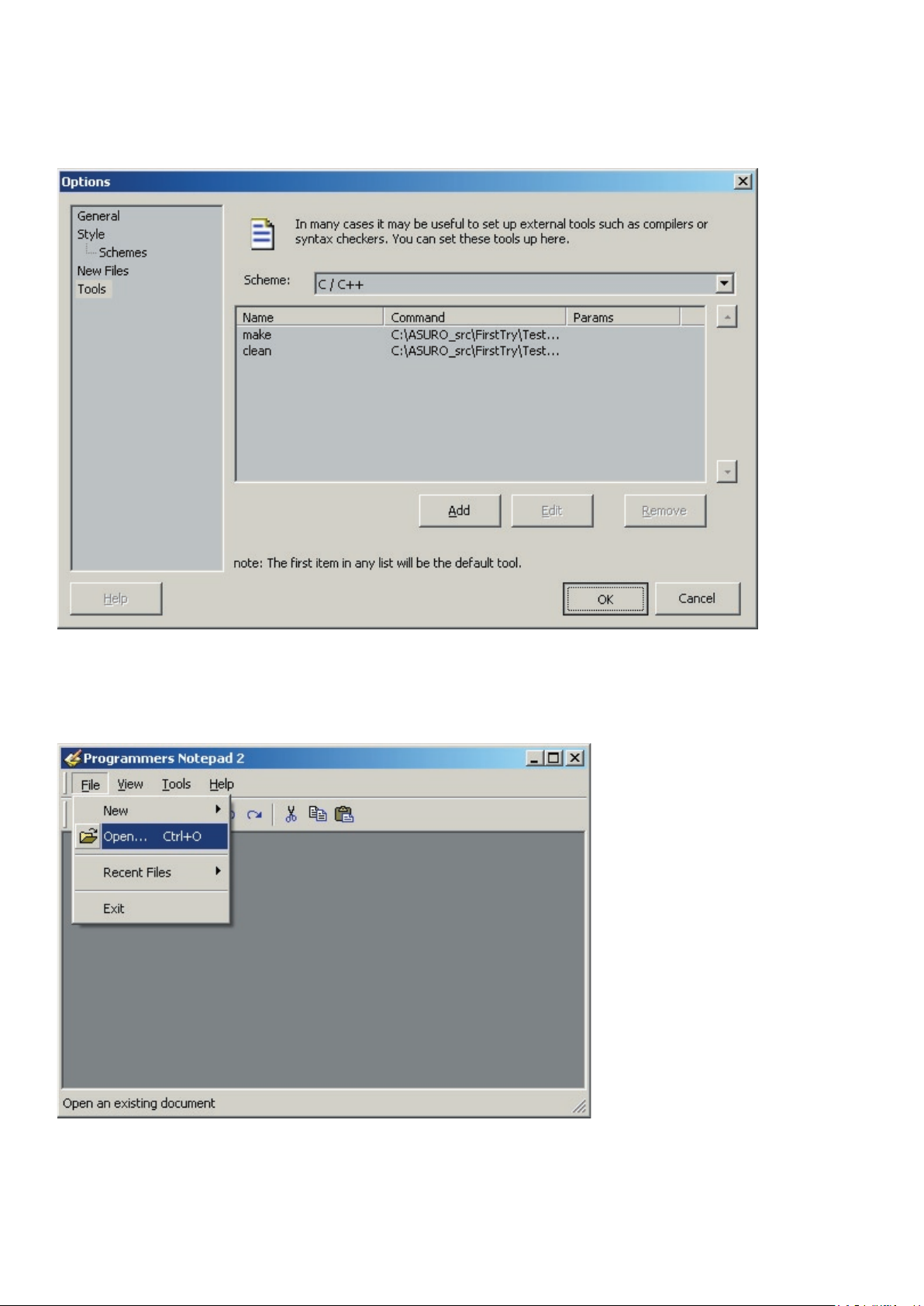
A new PN2-tool with the name “clean” is now available in the tools main menu.
Page 44
ASURO - 44
Software
Page 45
ASURO - 45
-
Software
Page 46
ASURO - 46
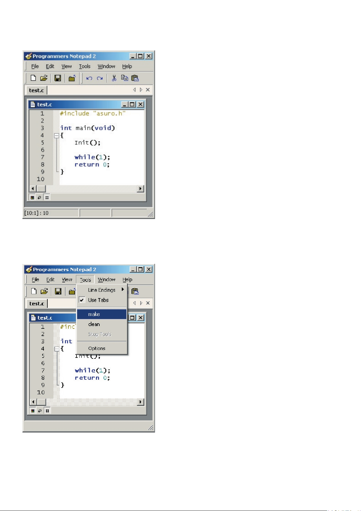
Software
When you choose tools…
Page 47
ASURO - 47
-
Software
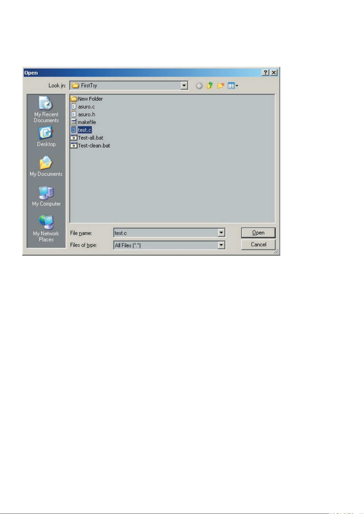
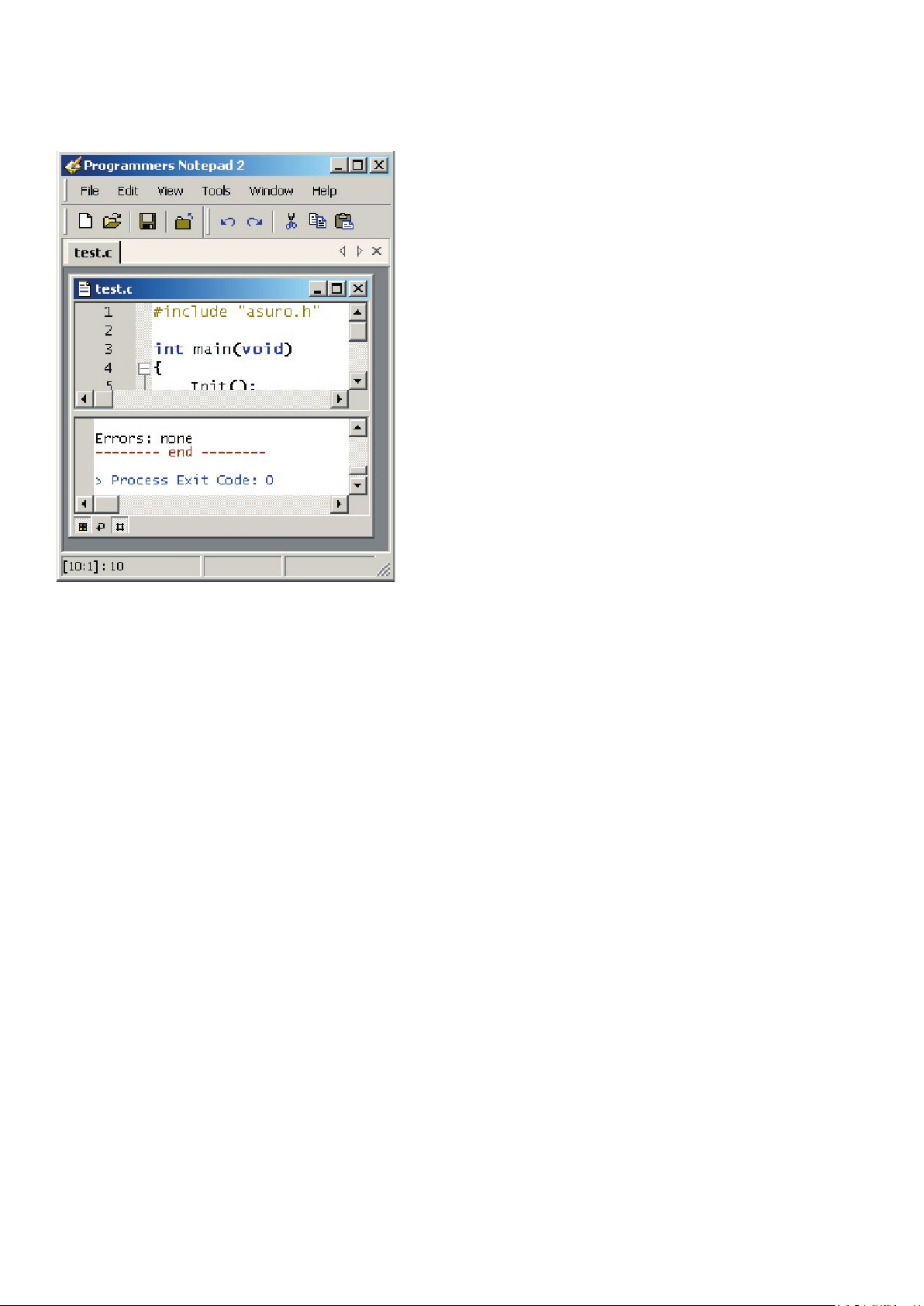
The le test.c (together with asuro.c) will be compiled now…
just loaded an example program), on the bottom this message will appear: Errors: none.
What happened?
ASURO’s memory. This program does not have a function. Later on, for trial, we will upload it in
the ASURO memory with the Flash tool.
The menu input le calls the batch le Test-all.bat ( this batch le contains a list with command
A make le is a text le, which de nes how to compile one or more programs. During
the correct way step by step and also connected (linked) with each other in a proper way, then
The “all” calls for all the input in the make le means, that a complete project and not only the
Page 48
ASURO - 48
Software
The make le in our example program is written in a way that a le with the name test.c will be
Attention! This means that - as long you do not change the make le and you
When you want to know all about make les (This is not absolutely necessary for operating the
ASURO) you can nd more background information at
http://www.gnu.org/directory/make.html
The basics about ASURO-programming will be explained in chapter 9.
When you compile a program, some extra data is generated. This data is only necessary during
the conversion, after that they are useless. These data les can be removed with the clean tool
which we just created.
Page 49
ASURO - 49
-
Software
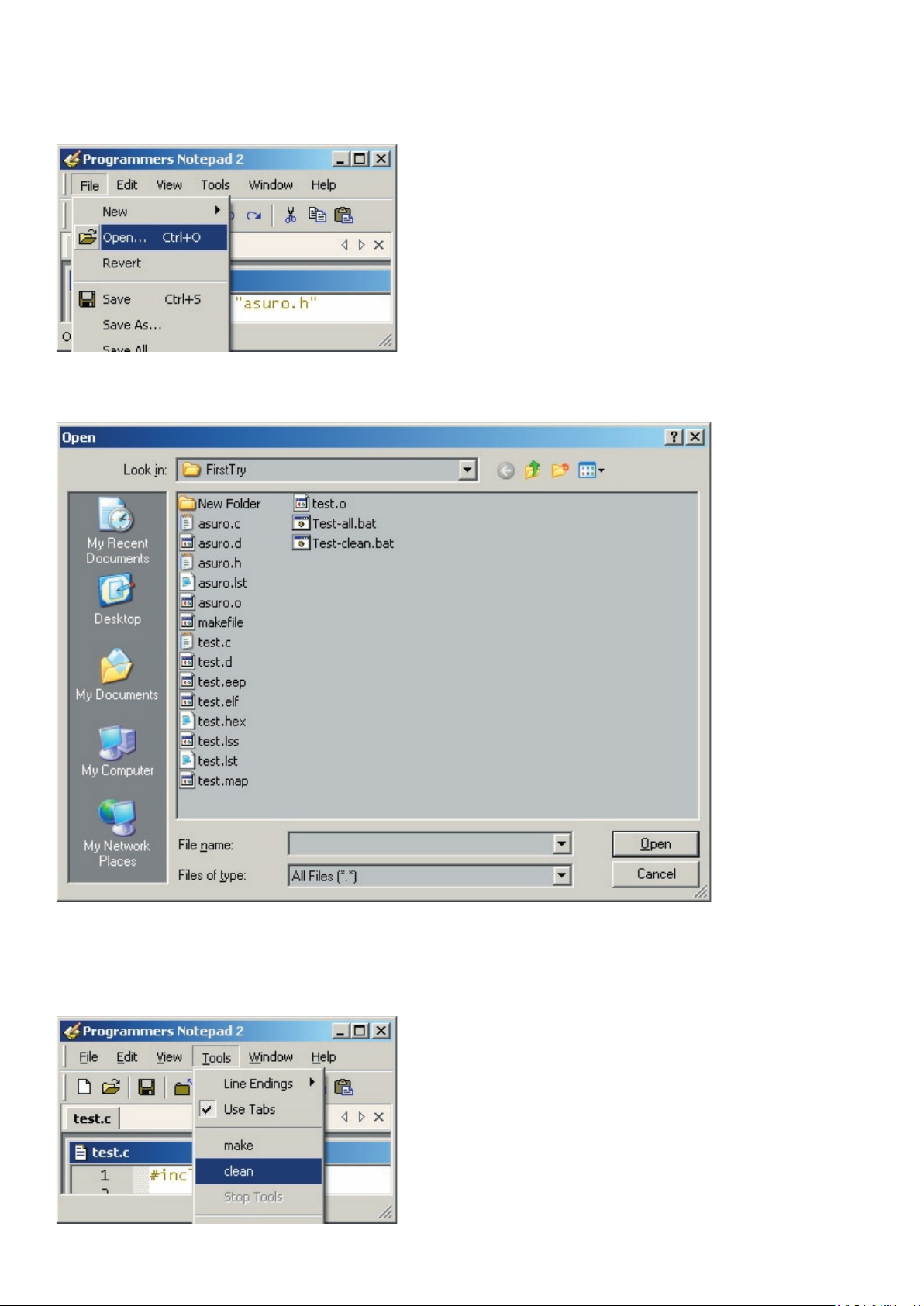
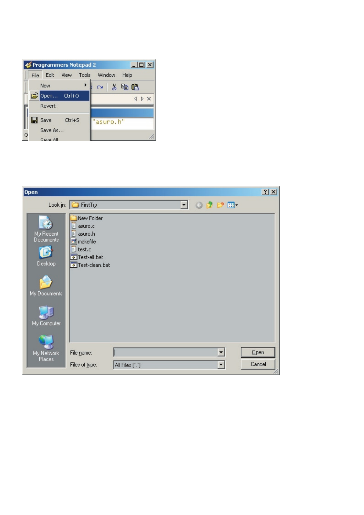
When you open it.…
Page 50
ASURO - 50
Software
What did happen?
The menu input “clean” calls for the batch le Test-clean.bat. Make started this with the parameter
Page 51
ASURO - 51
-
Software
8.2. LINUX
For the software installation you need root rights. If you do not have this log out and log in again
as root or open a shell and demand the root with ‘su’.
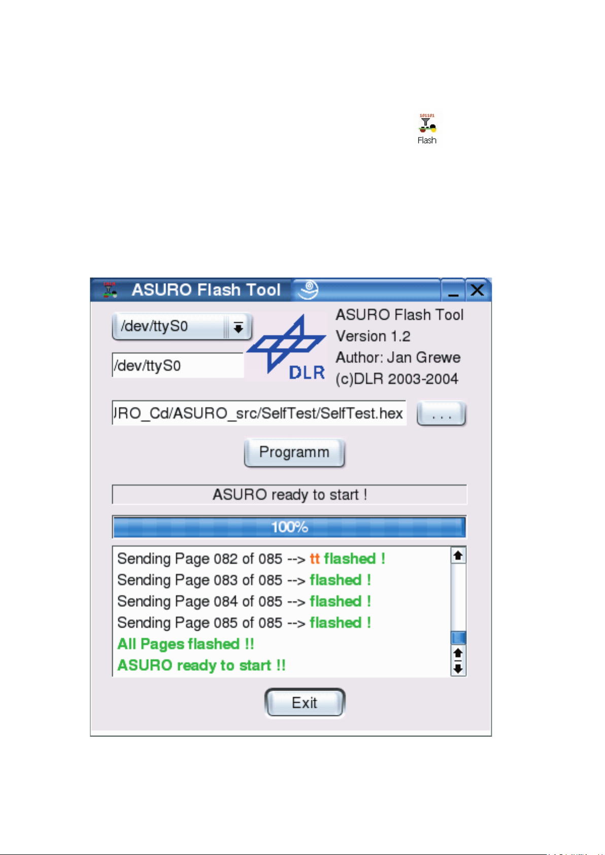
8.2.1 Flash - The ASURO-programming-tool
Start the program from the CD software menu and copy the two ash tools “asuro ash” and
“asurocon” from the folder “/linux/tools” into the folder “usr/local/bin”. After this, you must alow the
execution of the program with “chmod a+x/usr/local/bin asurocon and asuro ash.
Fig. 8.1.: Flash-Tool
Page 52
ASURO - 52
To instal the Gnu-Compilers for AVR-Processors insert the ASURO-CDROM choose from the
folder “/Linux/Compiler/” the folowing:
1. avr-binutils-... .rpm
2. avr-gcc-... .rpm
3. avr-libc-... .rpm
The Installation is quite simple!
Just give the command: rpm -i <paket>.rpm
in your root directory
.
Ready!
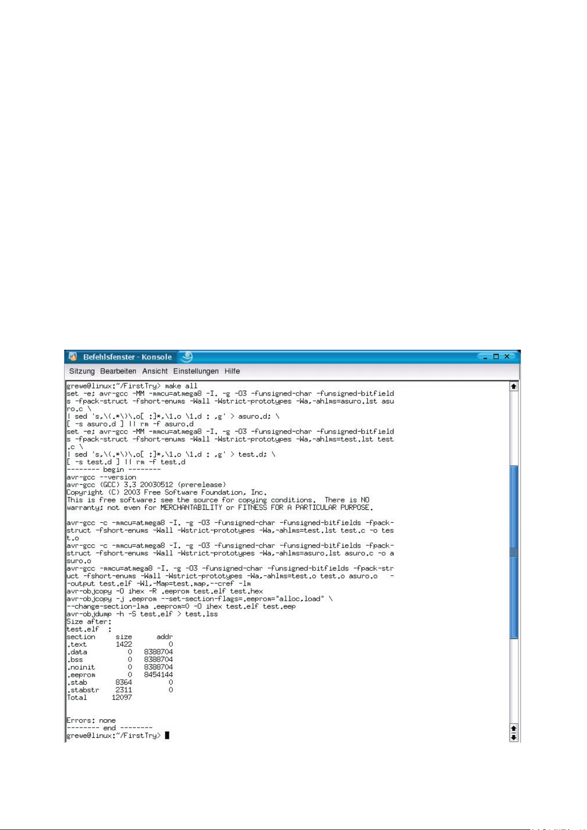
the CD. You can nd this in the folder “/ASURO_src/FirstTry/”
Then you can open a Shell, change the folder and enter “make”. when all is OK you will see the
folowing window; (see g. 8.2)
g. 8.2.: Make all
Software
Page 53
ASURO - 53
-
8.3. Flash - The ASURO-programming-tool
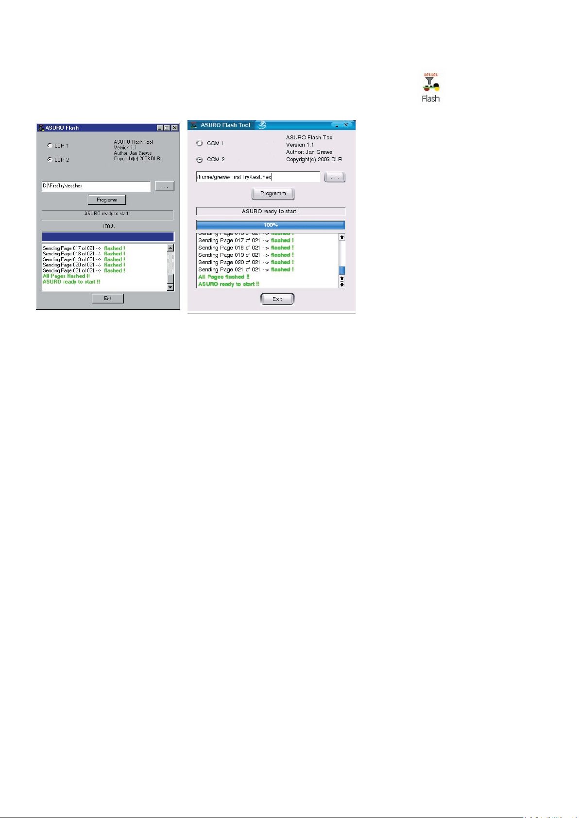
In this step we will need the Flash-Program (see g.
8.3).
Start the program and select the interface in which you have plugged the IR-Transceiver.
Select Test.hex
from directory
C:\Own les\ASURO_src\FirstTry.
Place the completely assembled and tested ASURO near the IR-Transceiver, at a distance of
max. 50 cm. The component sides of both PCBs must be facing and “seeing” each other. Click
the button Programm at the Flash-Tool. Now switch S1 to ON-position, before the status-indicator
reaches the right end of the status-area. If you have failed to react fast enough or communication
has been disturbed, just switch ASURO off , press Programm and switch S1 to ON-position again.
As soon as communication is succesful, you may observe how the le Test.hex is being
transferred to ASURO in the status-indicator and display. The program le will be stored in the
Flash-memory inside the processor, where the program remains available even after switching off
the supply voltage.
After loading the program, ASURO will have to be switched OFF and ON again in order to start the
program. This sequence will execute the loaded program and the green LED will be lit up brightly.
8.3.1. What is happening while ashing?
As soon as the Flash-program has been executed, the PC will be try to communicate with ASURO.
By switching on ASURO, the system will be booted, indicated by the Status-LED bi-colored lighting
for one second. ASURO is checking to see, if new software has been prepared to be loaded. If
a new program has been found, it will be loaded. After loading, the program will be executed by
switching OFF and ON once again.
Software
Fig. 8.3.: Flash-Tools
for Windows and LINUX)
Page 54
ASURO - 54
Software
8.4. Flash failures
The following errors may occor while ashing:
“c” Checksum Error. ASURO has received some irregular signals. Signals may have been
disturbed by other optical sources, such as uorescent lights, or have been interrupted
shortly by movements.
“t” Timeout. The line-of-sight between ASURO and the IR-Transceiver has been interrupted
completely.
“v” Verify Error. ASURO wrote invalid data into its Flash-memory. This is a most unusual
situation, indicating the non-volatile programming memory (Flash-EPROM) has reached the
end of its lifetime, according to speci cations after approximately 10.000 programming
cycles.
Error correction can be retried ten times. In case of failure the ash-procedure will be aborted.
If Checksum Errors are being indicated regularly while Flashing, you may switch
off or dim some lights in the room, especially uorescent lights. Remember:
Always press the Program-button, before switching ON the ASURO.
Otherwise the download procedure will not be started.
8.5 Your rst program
In the programmers Notepad the loaded source le will be modi ed. Attention please: follow exactly
the text in the example, including upper case and lower case.
#include “asuro.h”
int main(void) {
Init();
StatusLED(RED);
while(1);
return 0;
}
Store the le and choose the menu Tools -> make, observing the messages in the display window.
Wait a few seconds until the program nishes the report. Check the status window for a bottom
line Process Exit Code: 0, indicating the source has been processed correctly by the compiler.
Page 55
ASURO - 55
-
The editor displays the line number in the source in the left bottom corner of the display window.
After a succesful translation you may deliberately alter a word in the program source. Restart the
make procedure and check, in which line number the “error” has been reported.
Following an error free compilation, the new program may be ashed. Connect the IR-Transceiver,
start the Flash-Tool, select the newly created program test.hex and the correct COM-interface.
Place ASURO near the IR-Transceiver, activate the Programm button and wait until the transfer of
the le has been completed.
After the statusline in the display has reported a succesful completion of the le transfer, switch
OFF ASURO and switch ON again. Wait a second and check the status-LED switching to red.
Before altering the source code, some more programming background should be available. It is
advised to read the following chapter rst.
NOTE!
It is also possible to load the demo program test.c from the Folder ASURO_src\FirstTry;
This program contains the lines below;
#include “asuro.h”
int main(void) {
Init();
while(1);
return 0;
}
It can be easy changed into the program on page 54.
Software
Page 56

ASURO - 56
9. C for ASURO
This chapter is devoted to the programming language C, but explanation will be limited to the
elements which are needed to control the ASURO system. Obviously the explanation is not a
complete C-manual, for which other literature may be found on the market1.
C has been chosen for its widespread standard and because a C-Compiler is available for almost
every processor. For ASURO we selected the Gnu-C-Compiler, a freeware program, which
generates a well optimized code for ASUROs ATmega8 processor.
Whoever is familiar with C will not read anything new in this part of the manual and may proceed
reading chapter 9.2.
We will describe selected elements, absolutely necessary for the ASURO
9.1. Basics in C-Programming
9.1.1. Introduction
Basically the processor executes commands in a C-program step by step from the beginning to
the end of the program
2
. Parallel processing cannot be provided in ASUROs standard processor,
so we will have to think in sequential working commands.
Empty spaces at the beginning of lines in examples, are simply structural reading aids and may be
left out. Inset spaces however provide excellent programming structure and are extremely helpful
keeping an overview in extended programs.
In C each command has to be completed with a semicolon “;”, enabling the compiler to assign all
elements to the correct command. If commands are to be joined in functions, loops or conditional
statements, this set of commands will be grouped by placing it inside a pair of special brackets
(“{”, “}”).
Example:
#include “asuro.h”
int main(void) {
/* All elements between these brackets belong to one set of commands */
}
1
For Example: Brian W. Kerninghan, Dennis M. Ritchie: “Programming in C”,
2
Methods to deviate from sequential control in programs ar being named „ ow control“ and will be
described in a later chapter.
Page 57
ASURO - 57
-
If we want to place a comment between programming lines, the set of comment words or lines
starts with “/*” and ends with “*/ ”. A single line may also be de ned to be a comment by starting
the line with “//“
3
. Transforming programming lines into comments is often used to exclude parts
of the program from being processed. The compiler will ignore all comments. Correctly inserted
comments will never cause problems in program execution.
9.1.2. Variables and Datatypes
In programming, variables are being used as container elements for data and they may be
de ned, lled, read or changed in the course of the program. In order to use a variable, it has
to be declared at rst. In declarations, variables will be assigned to types and they also may be
provided with an initial value. Types de ne which kind of data are to be stored inside the variable
(integer numbers, positive integers, real numbers, etc....).
Variables are referenced by names, which have to begin with a letter (underscore “_” will be
counted as a letter as well) and may also contain numbers, but none of the other special
characters. Capital letters and noncapital letters will be discerned. As an example: x and X
reference to different variables. Normally capital letters are being used for constants
(which cannot be changed in program ow, e.g. th number PI = 3.1415) and small letters are being
used for variables.
The following names are reserved words and cannot be used as names for variables:
auto default oat long sizeof union
break do for register static unsigned
case double goto return struct void
char else if short switch volatile
const enum int signed typedef while
continue extern
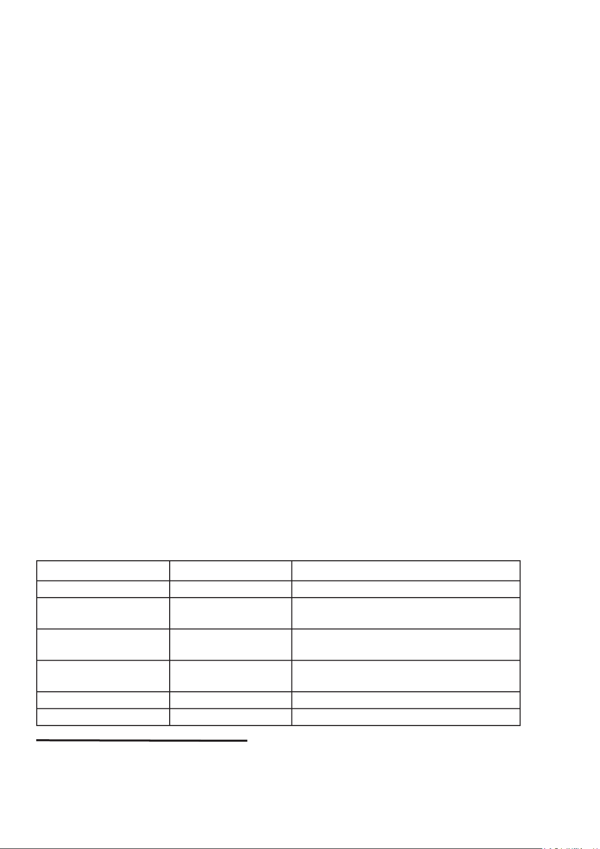
The following data types will be used for ASURO programming:
Type Range of values Remarks
char -128 ... +127
a (8 bit long) byte, may store a character
from the alphabet
unsigned char 0 ... 255
unsigned characters, may store positive
values only.
int -32768 .. +32767
two byte values in the range
-32768 .. +32767
unsigned int 0 ... 65535
positive integers in the range 0 ... 65535
oat
real numbers
3 According to C++ Standards “//” is a comment mark. In fact the compiler for ASURO is a
C++-Compiler and will understand “//” as a comment mark. “//” as a comment mark may
however cause problems in other compilers.
C for ASURO
Page 58

ASURO - 58
C for ASURO
Declaration of variables may be provided as global variable outside the main()-function or as a
local variable inside the main()-function. Global variables will be valid in the complete program
area. Local variables will be valid inside the main()-function or any other function only. They will
be valid for the programming code inside the function and they will be invalid outside the function.
Variables are rather useless, as long as we are unable to ll them with data. Assigning data is
however rather easy:
a=17; // variable a contains a value 17
or alternatively in a calculation:
a=17+23; // variable a contains a value 40
Speed=a+3; // variable Speed contains a value 43
Speed=Speed*2; // variable Speed contains a value 86
It is good programming practice to use clear understandable names. The variable name “speed” in
this example is self-explainable. Using simple letters as a variable should be restricted as it often
results in “unreadable” programming code.
The following example may demonstrate a simple, complete programming source:
#include “asuro.h”
int main(void) {
int i; // i may contain numbers between -32768 and 32767
char any_token; // variable any_token may contain ASCII-symbols or
// numbers between -128 and 127
i=3;
any_token =17+i; // any_token will now be assigned 20
i=i/2; // Division by 2, will always be rounded down
// therefore i will now be assigned 1!
return 0;
}
A few interesting shortcuts are useful in the programming language C, e.g.:
i=i+1;
may also be written as:
i++;
Equally:
i=i-1;
may be written as:
i--;
Page 59

ASURO - 59
-
C for ASURO
9.1.3. Compiler directives
You may have wondered about the rst program line #include “asuro.h”. This #include-directive
de nes an inclusion of an external source code into your program and orders the compiler to
include the text le in the compiler sequence. Our include- le contains some functions, which will
be needed for robot operations.
Another important directive (amongst others, which are lying beyond the scope of our introduction
to C) is the so called text replacement. This directive will be de ned by a pattern:
#de ne NAME replacement_text
and wil be used to de ne constants in our programs.
Wherever the symbol NAME is found in the source text, it will be replaced automatically by
replacement_text. For the NAME following #de ne the same naming conventions as for variables
have to be applied. C-programmers are used to writing the symbols (eg. NAME) at the #de ne in
capital letters.
Example:
#include “asuro.h”
#de ne STARTINGVALUE 33
int main(void) {
int i;
i= STARTINGVALUE; // the value for i is now 33
return 0;
}
Remark: Compiler directives are not closed by a semicolon!
9.1.4. Conditions
Sometimes we would like to execute commands under certain conditions. These conditional
sequences are called control structures. The simplest of these control structures is an “if-else”
sequence.
In “C” the correct syntax will be as follows:
if (Condition)
Command_block_1
else
Command_block_2
The program will check the value of the condition between the brackets. If the condition is true
(which implies any value except zero), the program will execute Command_block_1 and otherwise
the optional Command_block_2.
Page 60
ASURO - 60
C for ASURO
If the program should be able to choose one option out of several alternatives, you may use
several “else if”-constructs.
if (Condition1)
Command_block_1
else if (Condition2)
Command_block_2
else if (Condition3)
Command_block_3
else if (Condition4)
Command_block_4
else
Command_block_5
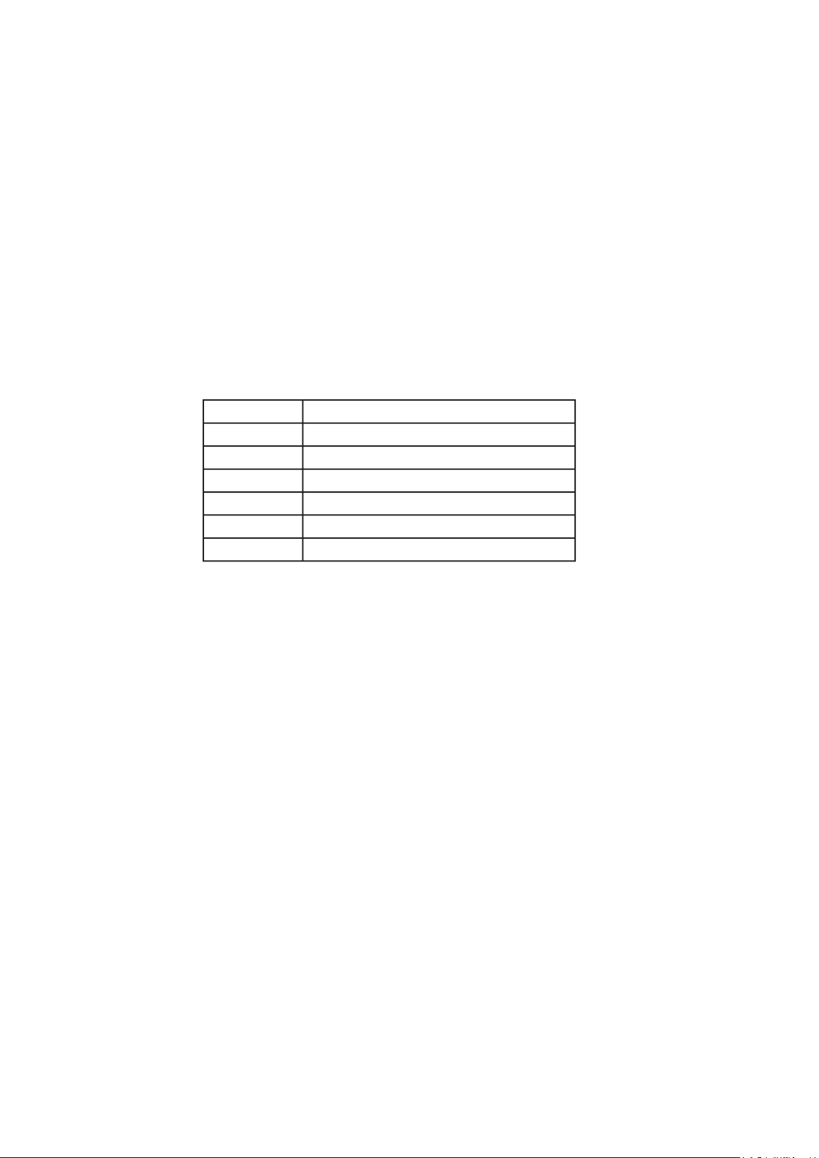
The following conditional structures may be used:
Example:
#include “asuro.h”
int main(void) {
while (1) {
if (PollSwitch()>0) {StatusLED(RED);}
else {StatusLED(GREEN);}
}
}
If one of the collision detector switches has been activated, the status-LED will be switched on red,
otherwise in green. The other programming code will be explained later.
In the C-language a value “1” represents true and “0” represents false.
The conditional statement:
if (0) {StatusLED(RED);}
of course implies the command StatusLED(RED) will never be executed.
Operator
Explanation
==
comparision for equal
!=
comparision for unequal
<
comparision for less
>
comparision for greater
<=
comparision for less or equal
>=
comparision for greater or equal
Page 61

ASURO - 61
-
C for ASURO
9.1.5. Loops
Loops are to be used to repeat command execution.
In a “while”-loop a condition is checked every time the loop is passed. If the condition is true the
command block will be executed. The condition is checked again until it turns to false. At a false
condition the program is continued at the rst command following the condition block.
while( Condition)
Command block
Example:
#include “asuro.h”
int main(void) {
MotorDir(FWD,FWD); // Both engines running forward
MotorSpeed(120,120); // Both engines running at around half speed
StatusLED(GREEN); // Turn on Status-LED green
while (PollSwitch()==0) { // As long as there is no collision
SerWrite(“All OK!\n”,10); // ... Feeling groovy ....
}
MotorSpeed(0,0); // Collision! Stop immediatedly!
StatusLED(RED); // Turn on Status-LED red
while (1) {
SerWrite(“Ouch!\n”,5); // start crying!
}
}
A “for (expr1, epr2, expr3)”- sequence is equivalent to:
expr1;
while( expr2) {
Command block
expr3;
}
A “for”-sequence is often used as counter sequence.
for (i = 0; i < n; i++)
. . .
Example:
#include “asuro.h”
int main(void) {
int counter; // de ne a variable for counting
for (counter =0;counter <10;counter ++) { // repeat ten times:
SerWrite(“Go ahead!\n”,10); // “Go ahead” message
}
MotorDir(FWD,FWD); // Both engines forward
MotorSpeed(120,120); // Both engines running at around half speed
while (1) { // No more action!
}
}
Page 62

ASURO - 62
9. C für ASURO
“while(1)” is equivalent to “for(;;)”, and both are eternal loops as the abort condition (in this case a
value 0) will never be reached.
Another loop sequence is a “do”-loop
do
command block
while( condition);
In contrast to a “while”-loop the condition will be checked after the command block. This
programming sequence forces the command block to be executed at least one time.
9.1.6. Functions
A de nition block for a function always looks like:
Functions type Functions Name (ParameterType1 ParameterName1,
ParameterType2 ParameterName2, ...)
Really great, de nition blocks for a function! Why so complicated???
Well, they are very useful, but their explanation is rather complex and may be postponed...
Sometimes we need to use the same programming sequences at different locations in our
programs. Of course we might repeat the writing or use a copy/paste-method for this purpose (this
is an annoying procedure and turns our program into a mess) or we just de ne a funtion.
Now sometimes we need to pass a few variables to a function, eg. telling our GoAhead () -function
to use a given speed exactly, a certain lapse of time or a de ned distance. We will use parameters
for these details.
Sometimes a function will even return a value. A good example is the
HowManySwitchesHaveBe
enActivated () -Function, returning a value, which will be de ned somehow and somewhere within
the function-block. The value is returned by a return-command at the end of the function-body.
That’s why functions end with
return; or return number;.
A special function is the
main () -function, de ning the main body of a program. In ASURO the
main () -function will be executed at switching ON. Of course every program must be supplied
with a main () -function.
Page 63

ASURO - 63
-
C for ASURO
Now after some theory on data types and functions we would like to build a simple function,
multiplicating two 8-bit numbers and returning the result.
int Mult (char a, char b)
/* Function returns an int-value, is called Mult, and uses two char values for input */
{ // Begin function
int c; // Declaring variable c as an int
c = a * b; // calculate c
return c; // returning integer c
} // End of the function “Mult”
Now an example program, which will use the Mult-function we have de ned before:
int main (void) // Function main always returns an int and will not
// input any parameter
{ // Begin Function „main“
char mult1,mult2; // De ning two „char“-variables
int result; // De ning an int-variable for the result of multiplying
// variables mult1 und mult2
mult1 = 2; // assignment
mult2 = 10; // assignment
result = Mult(mult1,mult2); // calling the previously de ned function “Mult”
return 0;
} // End of function „main“
Page 64

ASURO - 64
C for ASURO
9.1.7. Pointers and vectors
Pointers and vectors will be described to an extent, needed for the ASURO-operations.
If we need to track data from the line tracing sensors or odometric sensors we will need vectors.
Their declaration is rather simple:
int lineData[2];
int odometrieData[2];
As you will recognize we will create two vectors (lData, oData) with 2 elements for linetracing and
for odometrics. By calling ASURO Function (LineData(), OdometrieData ()) element [0] receives
the value of the left sensor and element [1] receives the value of the right sensor.
We will demonstrate this method in an example:
If the right sensor receives more light than the left sensor, command1 should be executed
otherwise command2.
int lData[2]; // Provide memory space for measurement results
LineData(lData); // Reading measurement data
if (lData[1] > lData[0])
command1;
else
command2;
To use the serial interface functions (
SerWrite (), SerRead () ) we need character strings. These
will be declared as follows:
char message[] = “This is a text string”
In order to send a text string in ASURO, a function SerWrite() is called with appropriate
parameters. The rst parameter contains the text string or the variable containing the text string,
the second variable describes the number of characters to be sent, eg.:
SerWrite(message,20);
respectively
SerWrite(„This is a text“,14);
will transmit a message “This is a text” over the IR-Interface.
Page 65

ASURO - 65
-
C for ASURO
To receive characters, ASURO uses a function SerRead (). The rst parameter contains a variable
in which the received characters are to be stored. The second parameter de nes how many
characters will be received and the third parameter de nes a timeout: if within a certain time period
(a number of processor clock cycles) no data has been received the SerRead () -function will
be aborted. By using a number “0” however, the function will wait until all characters have been
received. An example will illustrate this function.
ASURO is to receive a message “Hi, here I am” by IR-interface. By a string de nition
char message [] = ”01234567890123456789”
we rst allocate some storage space for the expected text. Of course the storage space must be
big enough to contain the expected message.
SerRead (message,13,0)
Read 13 characters and wait until 13 characters have been received. We now consider the text
string
message with
9.2. Overview of the ASURO-Functions
A few functions have been developed to support ASURO’s programming. These functions are by
no means optimal solutions and for some purposes it is a good idea to write special functions.
All functions have been developed as de ned in declarations and may be understood by
inspecting the examples.
Just to avoid misinterpretations: controlling functions like motor-controls or display-functions
change a status, which will remain valid until changed again. A green LED display will remain
green until changed to another colour or switched off.
Page 66

ASURO - 66
C for ASURO
9.2.1. void Init(void)
This function will reset the microprocessor to its initial state and must always be executed at the
beginning of a program. If the function is missing, the processor does not even know, what to do
with its terminals. A simple ASURO program should at least look like:
#include “asuro.h”
int main(void) { // here we declare some variables
Init(); // here we insert our own function blocks
while(1); // eternal loop
return 0; // will never be executed
}
Why did we insert the eternal loop at the end of the main () -function? Normally the main () function will be closed by return 0; marking the end of the program. In ASURO however some
parts of old programs ashed earlier, may still remain in the memory and be executed, resulting in
strange effects. To avoid abnormal execution of old program fractions we “catch” the program after
execution in an eternal loop. This way we can be sure the program ends in a de ned state.
9.2.2. void StatusLED (unsigned char color)
The Status-LED (D12) will be switched OFF or ON. Valid parameter values are
OFF, GREEN, RED or YELLOW
Example:
The Status-LED will be switched ON in red by:
StatusLED (RED);
OK, OK, we will demonstrate a complete example program:
#include „asuro.h“
int main(void) {
Init();
StatusLED (YELLOW);
while(1); // eternal loop
return 0;
}
Page 67
ASURO - 67
-
C for ASURO
9.2.3. void FrontLED (unsigned char status)
The Front-LED (D11) will be switched ON or OFF. Valid parameters are ON respectively OFF
Example:
The front-LED will be switched on by:
FrontLED(ON);
9.2.4. void BackLED (unsigned char left, unsigned char right)
The Back-LEDs (D15 and D16) will be switched ON or OFF. The rst parameter describes the
state of the left back-LED (D15) while the second parameter describes the state of the back-LED
at the right side (D16). Valid parameters are ON respectively OFF
Example:
The back-LED at the right side (D16) will be switched ON and the back-LED at the left side (D15)
will be switched OFF by:
BackLED(OFF,ON);
9.2.5. void Sleep (unsigned char time72kHz)
This function will command the processor to wait some time. The waiting period may be de ned
by a parameter (unsigned char)4., containing a number of maximal 255 and counting cycles from a
72kHz-timer.
Example:
0,003s
The processor should sleep for ca. 3ms. ==>
1
= 216.
72KHz
The function sleep (216); will force the processor to wait for 3ms.
Sleep (216) ;
9.2.6. void MotorDir (unsigned char left_dir, unsigned char right_dir)
This function controls the direction of both engines and should be called before calling speed
FWD (Forward), RWD (Backward), BREAK (
Example:
The left motor should be moving forward, while the right motor is halted.
MotorDir(FWD,BREAK);
4
The authors have chosen this method deliberately, just to train the readers brains.
Page 68
ASURO - 68
C for ASURO
9.2.7. void MotorSpeed (unsigned char left_speed, unsigned char right_speed)
This function controls the motor speed for both engines. Maximum speed is 255 (unsigned char).
The motor will start rotating at a value of around 60, depending on mechanical conditions. The
parameter value in fact controls motor power and the rotational speed also depends on other
factors like friction or inclination in slopes.
Example:
The left motor is to move at maximum speed, the right motor not at all. The direction of movement
has previously been de ned by MotorDir ().
MotorSpeed (255,0);
9.2.8. void SerWrite (unsigned char *data, unsigned char length)
This function outputs data from ASURO by the serial IR-interface at 2400Bit/s, No-parity, 1 StopBit,
NoFlowControl. The rst parameter contains the reference to the data to be sent, while the second
parameter describes the number of characters to be sent.
Example:
A string „Hello how are you?“ should be sent by IR-interface:
SerWrite (“Hello how are you?”,18);
9.2.9. void SerRead(unsigned char *data, unsigned char length, unsigned int timeout)
Once you are able to transmit data by IR-interface, you may probably also wish to receive some.
The next function will allow you to do so. The rst parameter is a pointer to the storage address,
where you would like to store the message. The second parameter describes how many
characters are expected, while the third parameter describes a timeout period. Timeout is used to
prevent eternal waiting periods if less data than expected do arrive. If after a given timeout period
no more data arrive, the function will be aborted and the rst character in the received string will
be replaced by a ‘T’ (=Timeout). If you however de ne a third parameter ’0’, the function will not
abort, but wait, until the last of the expected number of characters has arrived.
As soon as this function has been executed ASURO will start moving. Sometimes the
program however results in unexpected movements and we must take care ASURO
Page 69

ASURO - 69
-
C for ASURO
Example:
The string „Go Ahead“ should be received and we want to be sure all characters do have arrived
at the ASURO before we continue operation.
#include “asuro.h”
int main(void) {
char data[8]; // allocate storage
Init();
SerRead (data,8,0); // Read data
MotorDir(FWD,FWD);
MotorSpeed(120,120);
while(1); // Eternal loop
return 0;
}
.
.
.
9.2.10. void LineData(unsigned int *data)
This function has been developed to read the light intensity of both phototransistors at the
bottomside of ASURO. You will have to de ne an address pointer to a dual integer location
in memory. The function will transfer the AD-converter values of measurement data by both
phototransistors. The rst integer value represents the converter value of the left (T9), the second
integer value represents the converter value of the right (T10) phototransistor. Maximum intensity
(brightness) is referenced by ’1023’, while total darkness
is referenced by ’0’. Normally these extreme values will not be found, and in practice measurement
values will be found in between.
Example:
Reading the light intensity of both phototransistors (T9, T10)
unsigned int data[2]; //Allocate storage
.
.
LineData(data);
data[0] contains the value measured by the left phototransistor (T9)
data[1] contains the value measured by the right phototransistor (T10)
Page 70
ASURO - 70
Of course you would like an example as a complete program:
#include “asuro.h” // Line tracing the easiest way
int main(void) {
unsigned int data[2]; // Allocate storage
Init();
FrontLED(ON); // Switch ON line trace illumination
MotorDir(FWD,FWD); // Both engines go ahead
while(1){ // Eternal loop, ASURO should follow
// a line eternally
LineData(data); // Read brightness data from Phototransistors
if (data[0]>data[1]) // left brighter than right
{MotorSpeed(200,150);} // ... speed up left motor
else
{MotorSpeed(150,200);} // ... speed up right motor
}
return 0;
}
9.2.11. void OdometrieData(unsigned int *data)
The function scans the re ected light-sensor: Both LED (D13, D14) are activated and the function
returns the AD-converter values of the phototransistors (T11, T12). As in the function LineData() a
storage area with two integer values must be provided, which will be lled by the function. The rst
integer value contains the AD-value delivered by the left (T11), the second integer value contains
the AD-value delivered by the right (T12) phototransistor. Maximum brightness is referenced by a
value ’0’ while absolute darkness is represented by value ’1023’ 5. Normally these extreme values
will not be found, and in practice measurement values will be found in between.
Example:
Scanning the re ected light-sensors.
unsigned int data[2]; //Allocate memory
.
.
OdometrieData(data);
data[0] containes data from the left phototransistor (T11)
data[1]containes data from the right phototransistor (T12)
Just to prevent misinterpretations: OdometrieData() does not provide the number of revolutions,
but the actual illumination at the re ected light-sensors. Discerning bright and dark levels, counting
light-dark transitions and counting the number of revolutions is left to be a programmer’s job.
5
To simplify the hardware circuit these values do not correspond to the values found in the line
tracing module.
C for ASURO
Page 71

ASURO - 71
-
C for ASURO
9.2.12. unsigned char PollSwitch (void)
This function scans the position of switches (K1-K6) and returns one byte, containing information,
which switches have been activated. Switch 1 will set the rst bit number 5, switch 2 will set the
second bit, ... switch 6 will set bit number 5,
Bit0 (1) -> K6
Bit1 (2) -> K5
Bit2 (4) -> K4
Bit3 (8) -> K3
Bit4 (16) -> K2
Bit5 (32) -> K1
Activating switches 1,3 and 5 will cause the function to return 42 (32+8+2 = 42).
To be sure, the function may be called several times in sequence to provide a “correct” answer.
Capacitor C7 rst must be discharged, which may take some time. If you scan the A/D-converter
prematurely, some unreliable data may be delivered.
Example:
unsigned char taste;
.
.
switch = PollSwitch();
if (switch>0) {MotorSpeed(0,0);}
Well, that’s it. Now it’s up to you to be creative.
Page 72

ASURO - 72
Part IV. Appendices
A. Partslist
Besides a table-tennis ball the following parts are needed to build an ASURO:
1x Printed circuit board ASURO
2x Motors Type Igarashi 2025-02
1x Diode 1N4001
8x Diodes 1N4148
4x Transistors BC 327/40 or BC 328/40
4x Transistors BC 337/40 or BC 338/40
1x Integrated circuit CD 4081BE
1x Processor ATmega 8L-8PC (preprogrammed)
1x IR-receiver SFH 5110-36
1x IR-LED SFH415-U
2x phototransistors SFH300
3x LEDs 5mm red bright diffuse or asymmetric wide-angle
1x Dual-LED 3mm
2x Side-phototransistors LPT80A
2x Side-LEDs IRL80A
1x Crystal 8MHz
2x Elco 220_F at least 10V RM 3,5/10
4x ceramic capacitors 100nF RM 5,08
2x ceramic capacitors 4,7nF RM 2,54
1x 100Ω 1/4 W 5%
2x 220Ω 1/4 W 5%
4x 470Ω 1/4 W 5%
10x 1kΩ 1/4 W 5%
1x 1kΩ 1/4 W 1%
3x 2k 1/4 W 1%
2x 4,7k 1/4 W 5%
1x 8,2k 1/4 W 1%
1x 10k 1/4 W 1%
1x 12k 1/4 W 1%
1x 16k 1/4 W 1%
1x 20k 1/4 W 5%
1x 33k 1/4 W 1%
1x 68k 1/4 W 1%
1x 1M 1/4 W 5%
3x Socket 14 pol.
6x Detector switch
1x Switch (main on/of)
1x Battery holder
1x Battery clip
1x Jumper
1x Jumper pins 2pole RM 2.5
2x Cogwheel 10/50 cogs; 3,1mm drilling hole Module 0,5
2x Cogwheel 12/50 cogs; 3,1mm drilling hole Module 0,5
2x Pinion gear 10 (oder 12) cogs; drilling hole 1,9mm Module 0,5
2x Collar for 3mm-axle
Page 73

ASURO - 73
-
Appendices
A. Partlist
4x Cable binder
1x Cable binder releaseable
2x Rubber tires 38mm
2x Messing shaft 42mm long 3mm diameter,
2x Messing shaft 24,5mm lang, 3mm diameter
ca. 15 cm wire red 0,14mm_
ca. 15 cm wire black 0,14mm_
2x Encoder sticker (see 2.4)
The additional RS-232-IR-transceiver will be equipped with the following parts:
1x Printed circuit board IR-RS232-transceiver
3x Diodes 1N4148
1x Zenerdiode ZPD5.1
1x Transistor BC547 A,B or C or BC548 A,B or C
1x Integrated circuit NE555N
1x IR-receiver SFH 5110-36
1x IR-LED SFH415-U
1x Elco 100_F at least 16V RM 2,5/6
2x ceramic capacitors 100nF RM 5,08
1x ceramic capacitors 680pF RM 2,54
1x 220Ω 1/4 W 5% or better
1x 470Ω 1/4 W 5% or better
1x 4,7KΩ 1/4 W 5% or better
1x 10KΩ 1/4 W 1%
2x 20KΩ 1/4 W 5% or better
1x Trimmer 10k vertically mounted RM 2,5/5
1x Socket 8 pole
1x 9-pol. SUB-D-entry
Optional there is a USB-IR-tranceiver available:
Page 74
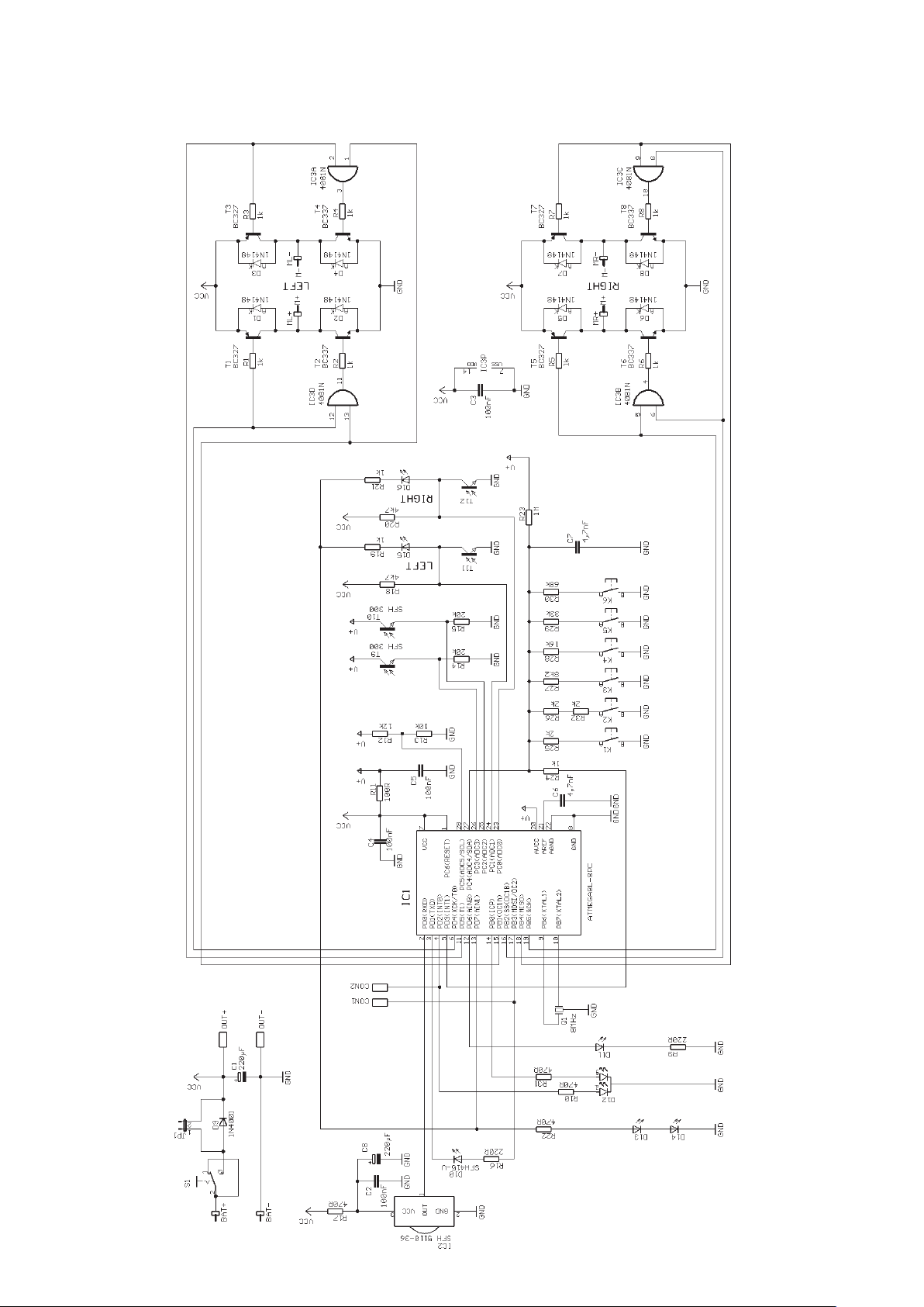
ASURO - 74
B. ASURO DIAGRAM
Appendices
Page 75
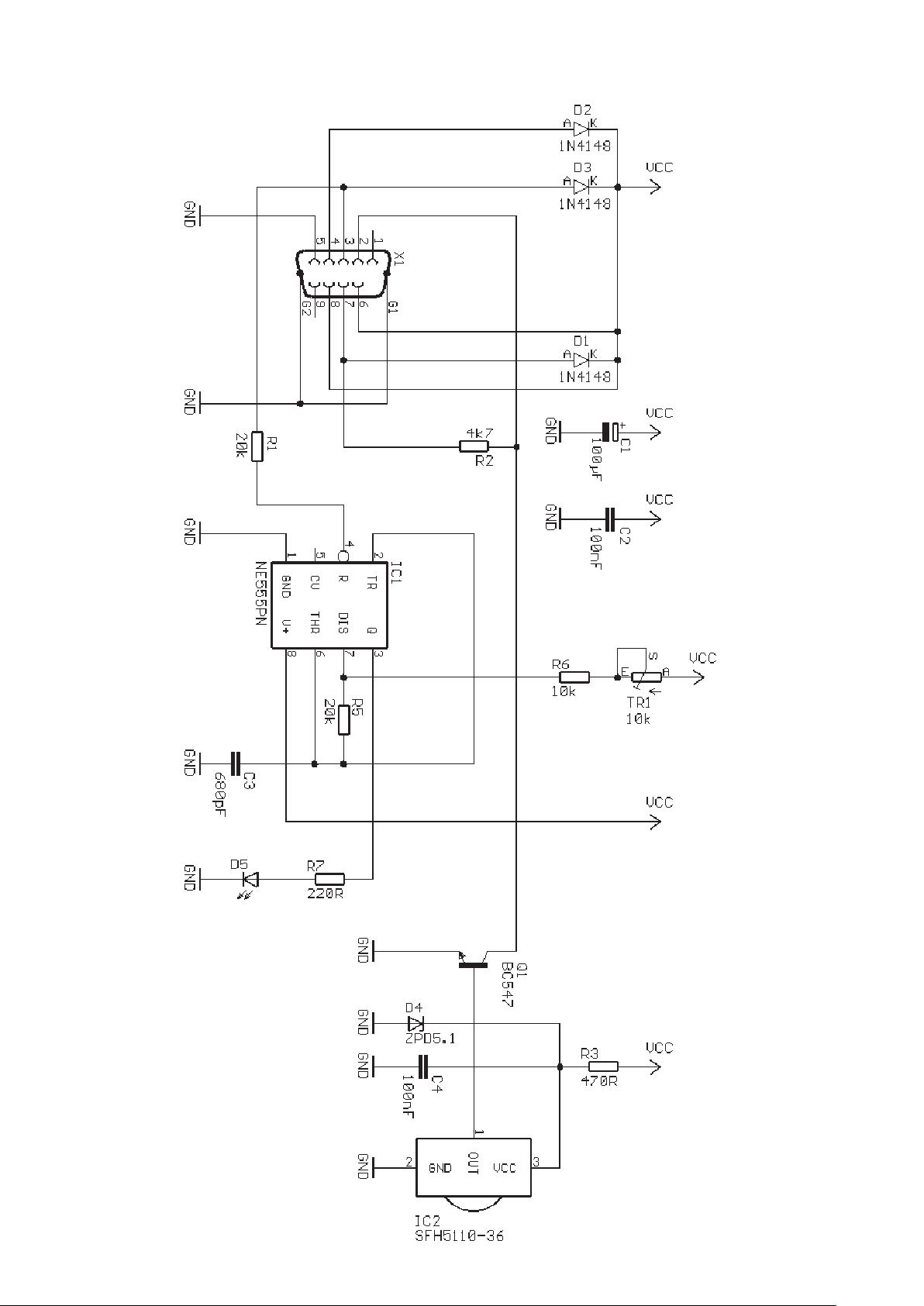
ASURO - 75
-
Appendices
C. RS-232 Transceiver
Page 76
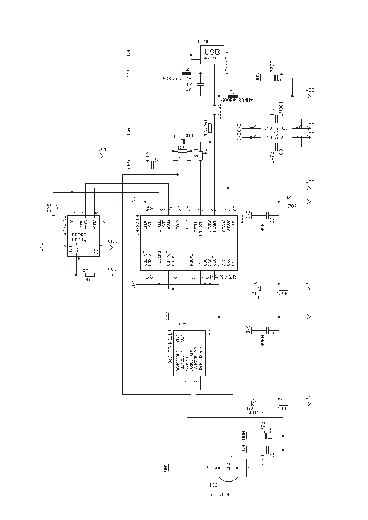
ASURO - 76
D. USB Transceiver
Appendices
Page 77
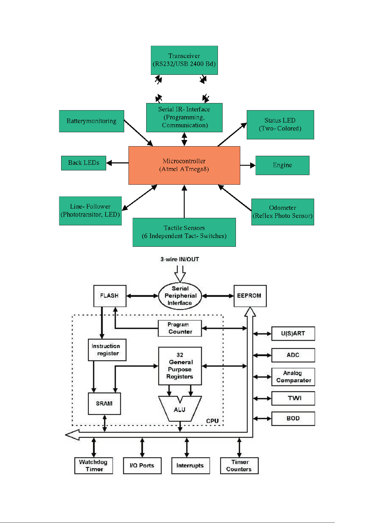
ASURO - 77
-
E. Block diagram
ASURO
F. Block diagram PIC processor
Appendices
Page 78
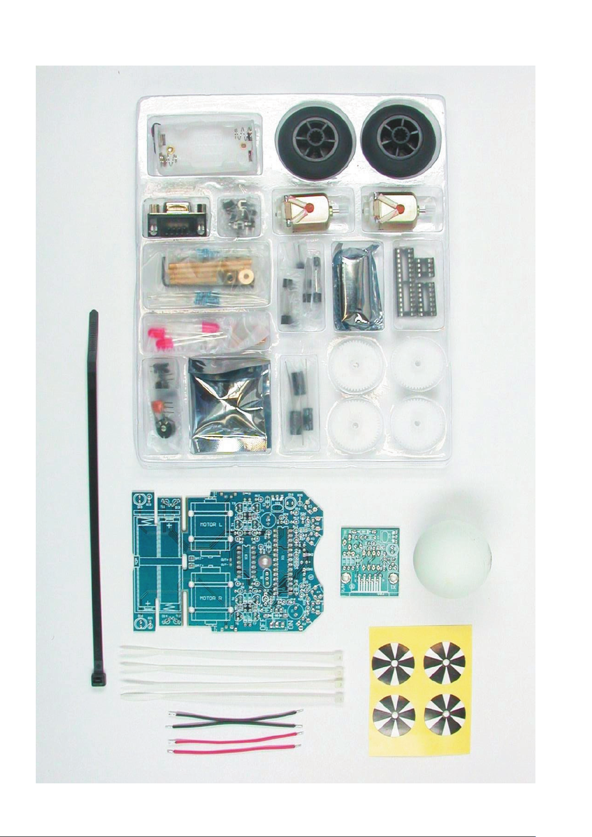
ASURO - 78
-
G. Contents ASURO KIT
Appendices
 Loading...