

Page 1
Page 2

2
Table of contents
1. Introduction ........................................................................................................................................................ 3
2. Technical parameters, characteristics .................................................................................................................. 4
2.1 Technical parameters ........................................................................................................................................ 4
2.2 Characteristics ................................................................................................................................................... 4
3. Connection diagram ............................................................................................................................................ 6
4. Installation of ASTmobile applications ................................................................................................................. 7
5. Work with the driver ........................................................................................................................................... 9
5.1 Establishing a connection to the driver using ASTmobile application ................................................................. 9
5.2 Driver PIN ........................................................................................................................................................ 11
5.3 Driver name and description ........................................................................................................................... 11
5.4 Driver date and time ....................................................................................................................................... 12
5.5 Switch-on and switch-off times of the outputs ................................................................................................ 13
5.5.1 Algorithm for determining switch-on/off times .................................................................................. 13
5.5.2 Driver position ................................................................................................................................... 14
5.5.3 Output operating time ....................................................................................................................... 15
5.6 Output mode ............................................................................................................................................. 15
5.6.1 Day operation mode (lighting day / 24-hour day) ............................................................................... 16
5.6.2 Correction mode ................................................................................................................................ 17
5.6.3 Switching intervals ............................................................................................................................. 18
5.7 Input mode ................................................................................................................................................ 21
5.7.1 Photocell configuration ...................................................................................................................... 21
5.7.2 Cascade configuration ........................................................................................................................ 22
5.8 Service switching ....................................................................................................................................... 23
5.9 Exceptions ................................................................................................................................................. 27
5.10 Recording events ....................................................................................................................................... 28
5.11 Replacement of internal driver software ....................................................................................................... 30
5.12 Factory settings ............................................................................................................................................. 31
www.astsystem.pl | [email protected]
Page 3

3
1. Introduction
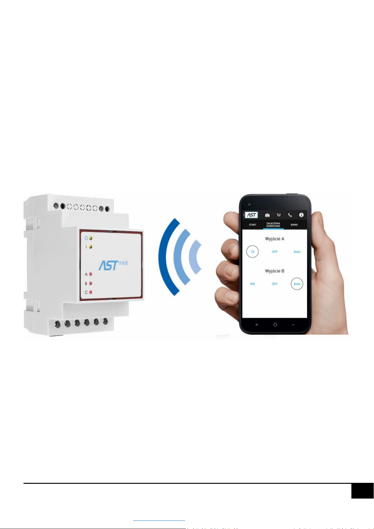
ASTmidi / ASTmidi GPS - a street lighting driver. It has two or three independent outputs, a photocell/cascade input
and a built-in Bluetooth. ASTmidi / ASTmidi GPS, depending on the GPS position, will calculate the optimal lighting
control time. If you want, you can modify the parameters for summer/winter, each month, day of the week, and 20
exceptions. You can protect your ASTmidi / ASTmidi GPS with a password and find it on the map, and with report data
you can fine-tune your settings.
ASTmobile - higher performance and work comfort are not only given to you by a driver adapted to your needs, but it
is also an application that so many have forgotten about. We are the first company to give you a powerful tool,
completely free of charge. ASTmobile. It's an application for your phone which will make working with the driver easy,
fast and fully professional. You will find your AST directly from your car, without opening the cabinet, see how it is set
up, modify the parameters and as part of the service switch on lighting if needed. You can remotely read its time,
switch-on times, map location and download reports. On the map you can find your driver offline and Google Maps
Navigation will lead you to it.
The ASTmidi driver is available in 2 output versions: 2 or 3 outputs.
ASTmidi comes in standard (ASTmidi) and GPS (ASTmidi GPS) versions. GPS can have a built-in or external antenna.
This manual describes the 3-output model for ASTmidi and ASTmidi GPS.
In the 2-output version, output C is inactive.
www.astsystem.pl | [email protected]
Page 4

4
2. Technical parameters, characteristics
2.1 Technical parameters
supply voltage: 85 - 305V AC / 50 Hz
number of outputs. 2/3 - independently programmable
Current ratings of the outputs: 5 A / 230 VAC
number of inputs: 1 - voltage input 230 VAC
cable size: 2.5 mm2 / AWG14
battery backup: 5 years
interface: Smart Bluetooth 4.0
Dimensions (width/height/depth): 53 mm x 95 mm x 58 mm
operating temperature: -30˚C to +80˚C
tightness: IP 20
DIN rail mounting 35mm
2.2 Characteristics
full control and management via phone, smartphone, tablet from the AST mobile application
intuitive application interface for easy entry of driver settings
free AST mobile application
Smart Bluetooth 4.0 communication
possibility of time synchronization according to GPS (or for phone without GPS)
automatic change of summer/winter time
astronomical switch-on and switch-on times calculated from the GPS position or taken from a table
built-in switch-on table and possibility of its editing and reloading to the driver by means of Bluetooth
automatic driver location on the AST mobile application map
2 or 3 independently programmable outputs with a possibility of entering up to 4 switching intervals for
each day of the week
20 exceptions to the switch-ons.
3 operating correction modes for astronomical summer-winter, quarterly, monthly switch-ons
Possibility of service switching of the A and B outputs for 1, 10, 30 minutes and permanently.
recording of events (switching on/off the A output, switching on/off the B output, switching on/off input 1,
power failure, power return) up to 600 records
possibility of sending recorded events from the application via e-mail, MMS, etc.
possibility of saving the current driver configuration as a settings bank and possibility of sending from the
application via e-mail, Bluetooth, etc.
www.astsystem.pl | [email protected]
Page 5

5
registration of operating time of A, B and C outputs
cooperation with photocell
cooperation with cascade signal
possibility of remote exchange of internal driver software by means of Bluetooth from the AST mobile
applications
LEDs on the front panel indicating the status of A, B and C outputs and power supply
blocking access to driver by means of PIN code and one-time passwords
possibility of restoring factory settings
www.astsystem.pl | [email protected]
Page 6
Page 7
7
4. Installation of ASTmobile applications
In order to install AST mobile applications you have to meet three conditions:
You must have an Android phone version 4.0 or more recent.
The phone should have a minimum resolution of 480 x 800, for smaller resolutions the application may also
be installed, but some interface elements may not be displayed correctly.
You should have a Google account added to your device. Instructions on how to add an account can be found
at https://support.google.com/googleplay/answer/2521798?hl=en or watching the video on YouTube
https://www.youtube.com/watch?v=ibkJKgGUp1o
The AST mobile application interface is suitable for both smartphones and tablets.
There are two ways to install AST mobile:
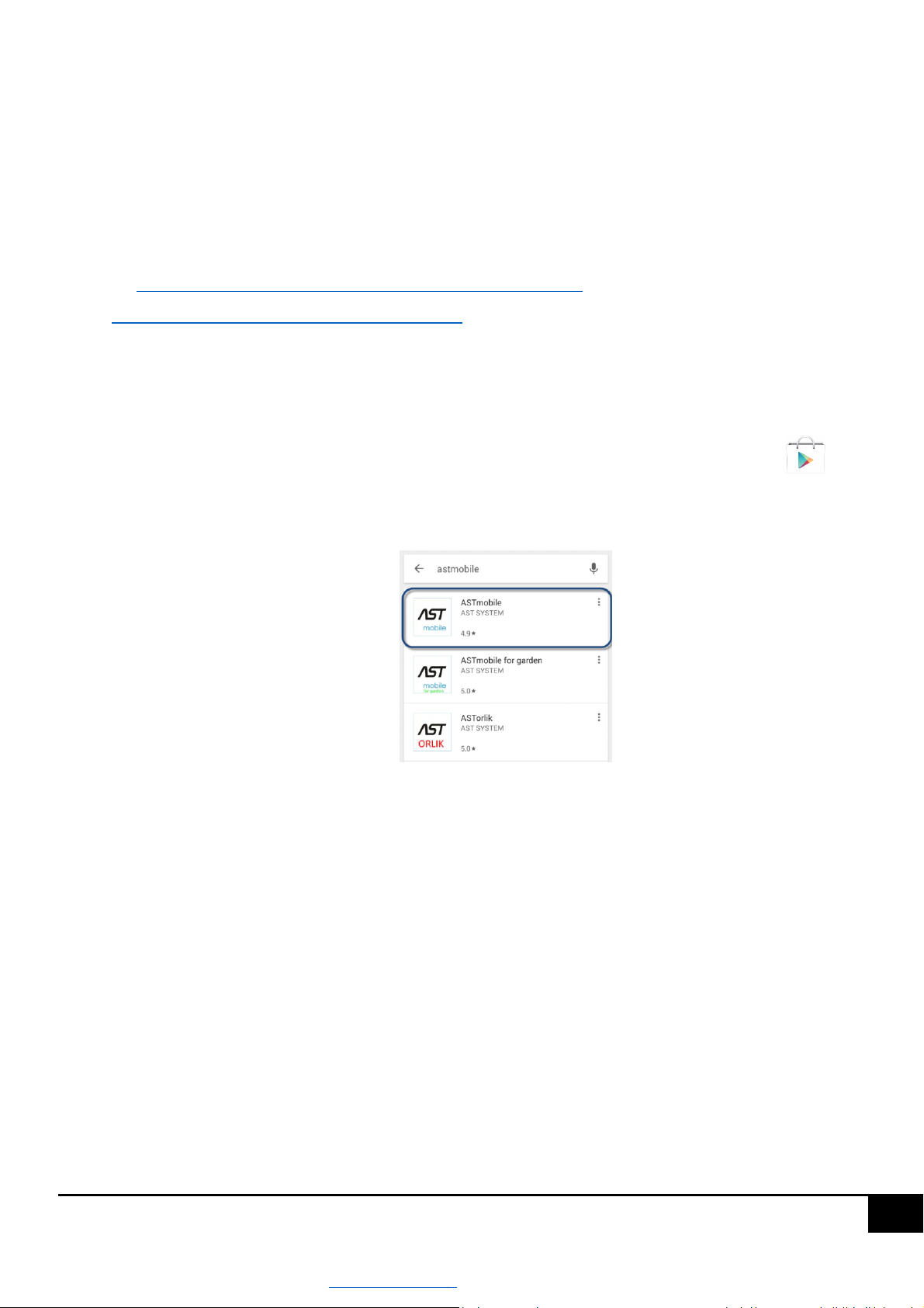
Using the Google Play application on your phone, to do so run the application by pressing the icon , then
enter the phrase astmobile or ASTmidi in the search window and press the search icon, the application will
appear below the search window, as shown in the figure,
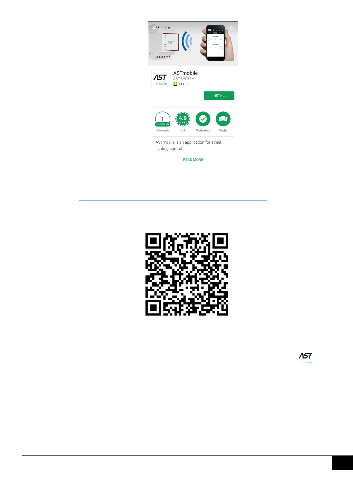
then select the ASTmobile position and the application description window will appear,
www.astsystem.pl | [email protected]
Page 8
8
then press the "Install" button, after a short while the AST mobile will be installed on your phone.
using the link https://play.google.com/store/apps/details?id=rob.astroterion.astmini or scanning the QR code
figure below.
After selecting the link or scanning the QR code, we will be moved directly to the window with application
description and then, as in the previous point, press the "Install" button.
After performing the above steps, the AST mobile application icon should appear in your phone .
www.astsystem.pl | [email protected]
Page 9
9
5. Work with the driver
The ASTmidi / ASTmidi GPS driver for factory settings is ready for operation. After connecting the power supply, driver
outputs will be switched on at sunset +15 minutes, and switched off at sunrise -15 minutes. Sunrise and sunset times
for factory settings are for the city of Warsaw. It is possible to sell the driver with programmed different location for
factory settings.
All parameters of the driver are subject to configuration. The AST mobile application is used to change them. In the
following sections it will be explained how to configure the driver using the ASTmobile application.
5.1 Establishing a connection to the driver using ASTmobile application
Assuming that you have an application installed on your phone, in order to establish a connection with the driver you
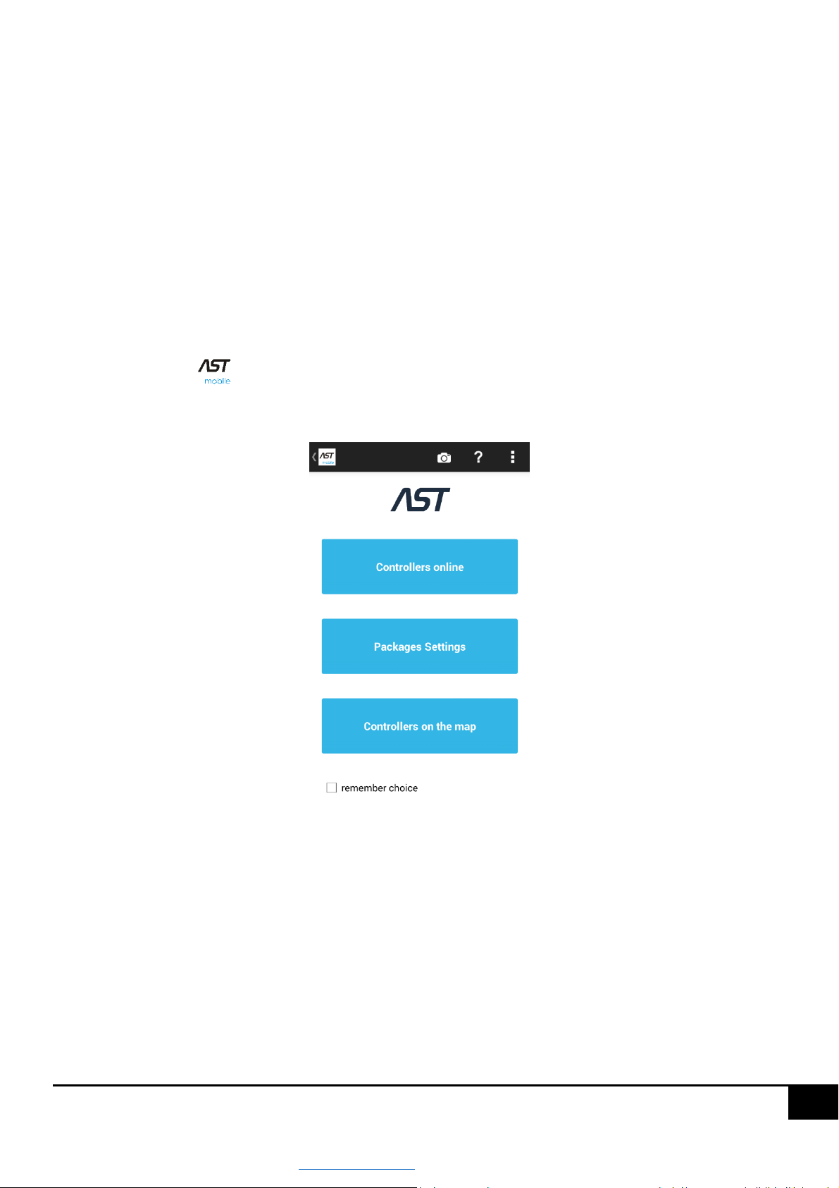
should press the icon to launch the AST mobile application. After a short time, the screen for selecting the
application operating mode will be displayed, see the figure below.
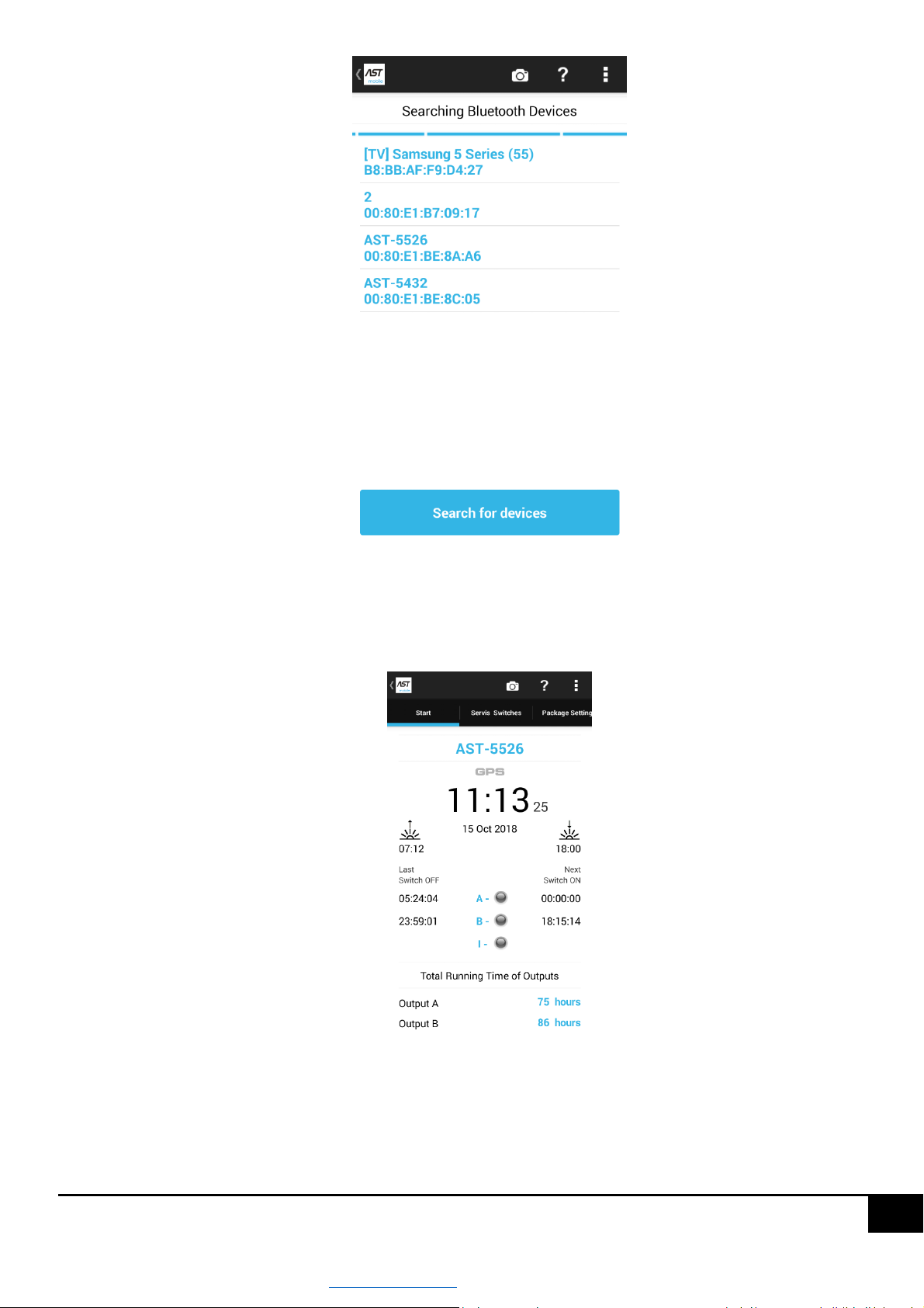
Select "Online drivers". This will bring up a window with a list of available ASTmidi drivers (the driver search time can
take up to 60 seconds, but it usually takes up to a few seconds).
www.astsystem.pl | [email protected]
Page 10
10
Then choose the position of our driver (for factory new drivers its name is AST-XXXXXX). This will cause a connection
to the controller and displaying the main application window and basic parameters of the driver such as date and time,
status of outputs, future switch-on times, etc. figure below.
Correct operation of the driver is the increasing amount of the driver time.
www.astsystem.pl | [email protected]
Page 11
11
CAUTION!!! - In the ASTmobile application each parameter displayed in blue is editable. If you want to edit a
selected parameter, press it. The exception is the driver time, which is displayed in black. Pressing it will make it
possible to synchronize the driver time.
5.2 Driver PIN
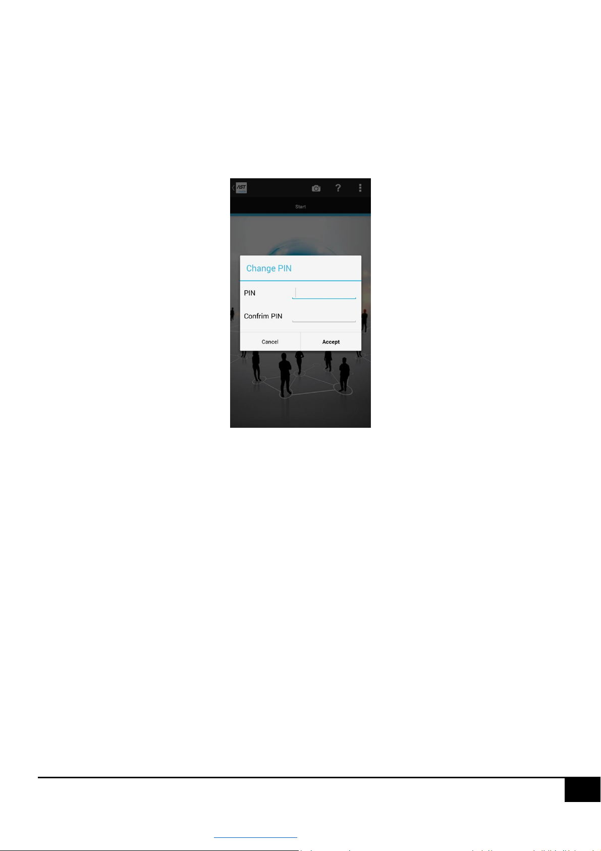
When you first connect to the driver using AST mobile, you will see the Change PIN window, in which you need to
establish a PIN to protect the driver, see figure below.
Enter the same four-digit code in the "PIN" and "Confirm PIN" fields and then press the "Save" button. From this point
on, the driver will be protected by that PIN code.
If you connect to the driver from a phone on which the PIN has already been entered once, the window for re-entering
the PIN code will not be displayed. However, if you establish a connection with the driver from a phone from which
you establish a connection with the driver for the first time, the PIN code entry window will be displayed.
CAUTION!!! Only entering the correct PIN code will enable further configuration of the controller.
5.3 Driver name and description
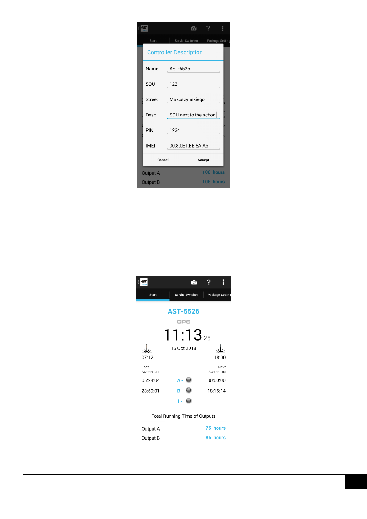
Driver name is displayed at the very top of the "START" screen of the AST mobile application, it is the first screen
displayed after establishing a connection with the driver. In order to change the name of the driver press the name (in
case of a factory new driver it will be AST-XXXX). This will display a dialog box allowing to change the name and add
additional description of the driver, as in the figure below.
www.astsystem.pl | [email protected]
Page 12
12
In the driver description window it is also possible to change the PIN code protecting the controller.
CAUTION!!! - After entering all desired values, press the "Change" button in order to save the values.
5.4 Driver date and time
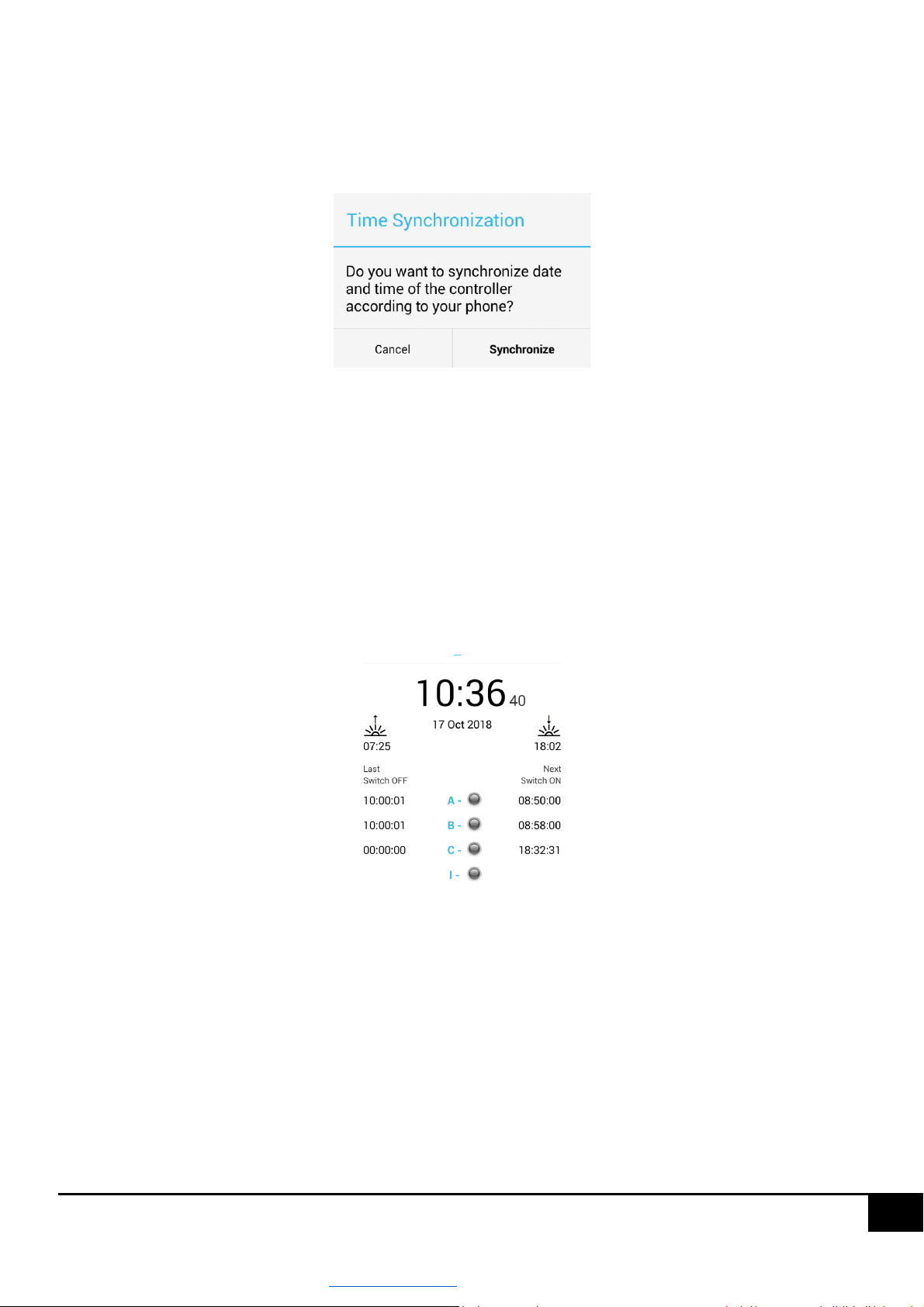
Always after establishing a connection with the driver, the current date and time of the driver is displayed on the
"START" screen, see figure below.
www.astsystem.pl | [email protected]
Page 13
13
If the date and time of the driver is within +- 3 minutes to the phone settings, it is displayed in black, if the difference
between the driver time and the phone time is more than 3 minutes, it will be displayed in blue, which suggests that
time synchronization should be carried out. In order to synchronize time, press the driver time. This will display a
dialog box with information about the confirmation of the time synchronization operation, see figure below.
Pressing the "Synchronize" button will set the driver to the same time as the phone.
5.5 Switch-on and switch-off times of the outputs
After establishing a connection with the driver, the following time related parameters are displayed on the START
screen below the date and time:
sunrise and sunset times for the current position of the driver.
the last switch-off times of A, B and C outputs of the driver
future switch-on times of A, B and C outputs for current driver settings
For the factory settings, the switch-on time is shifted by +15 minutes compared to the sunset time and the switch-off
time is shifted by -15 minutes compared to the sunrise time.
5.5.1 Algorithm for determining switch-on/off times
In the ASTmidi / ASTmidi controller the GPS astronomical switch-on and switch-off times of the outputs can be
calculated as follows:
Calculated from the GPS position, i.e. switch-on/-off time is equivalent to the sunrise/sunset time for the driver
current geographical position +15 minutes.
www.astsystem.pl | [email protected]
Page 14
14
Switch-on times taken from the table - in the factory settings driver there is a table for the center of Poland.
Of course, the switch-on tables can be modified and uploaded to the driver.
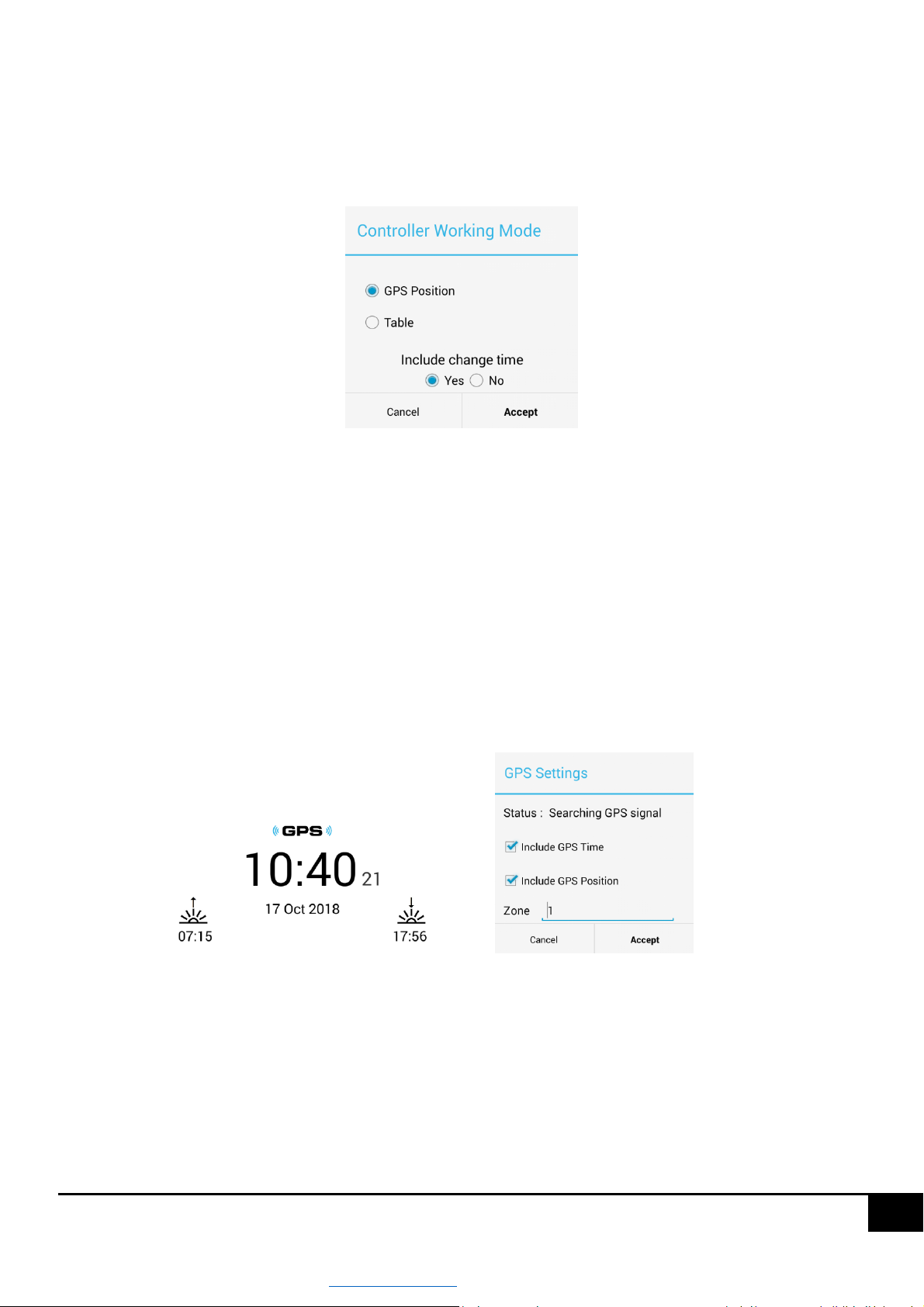
In order to change the algorithm of setting the switch-on times, press the value assigned to the operating mode from
the "START" screen level, see figure below.
This will open a dialog box allowing you to choose how to calculate the times. Then select the desired position and
press the "Set" button.
CAUTION!!! - For factory settings, the driver calculates astronomical switch-on times according to the driver GPS
position.
5.5.2 Driver position
For factory settings, the drives position is located in the centre of Warsaw.
The ASTmidi GPS driver will find the position itself. If you do not want the driver to locate its position by itself, press
the "GSM" button displayed over the time and uncheck "Allow for GPS position”.
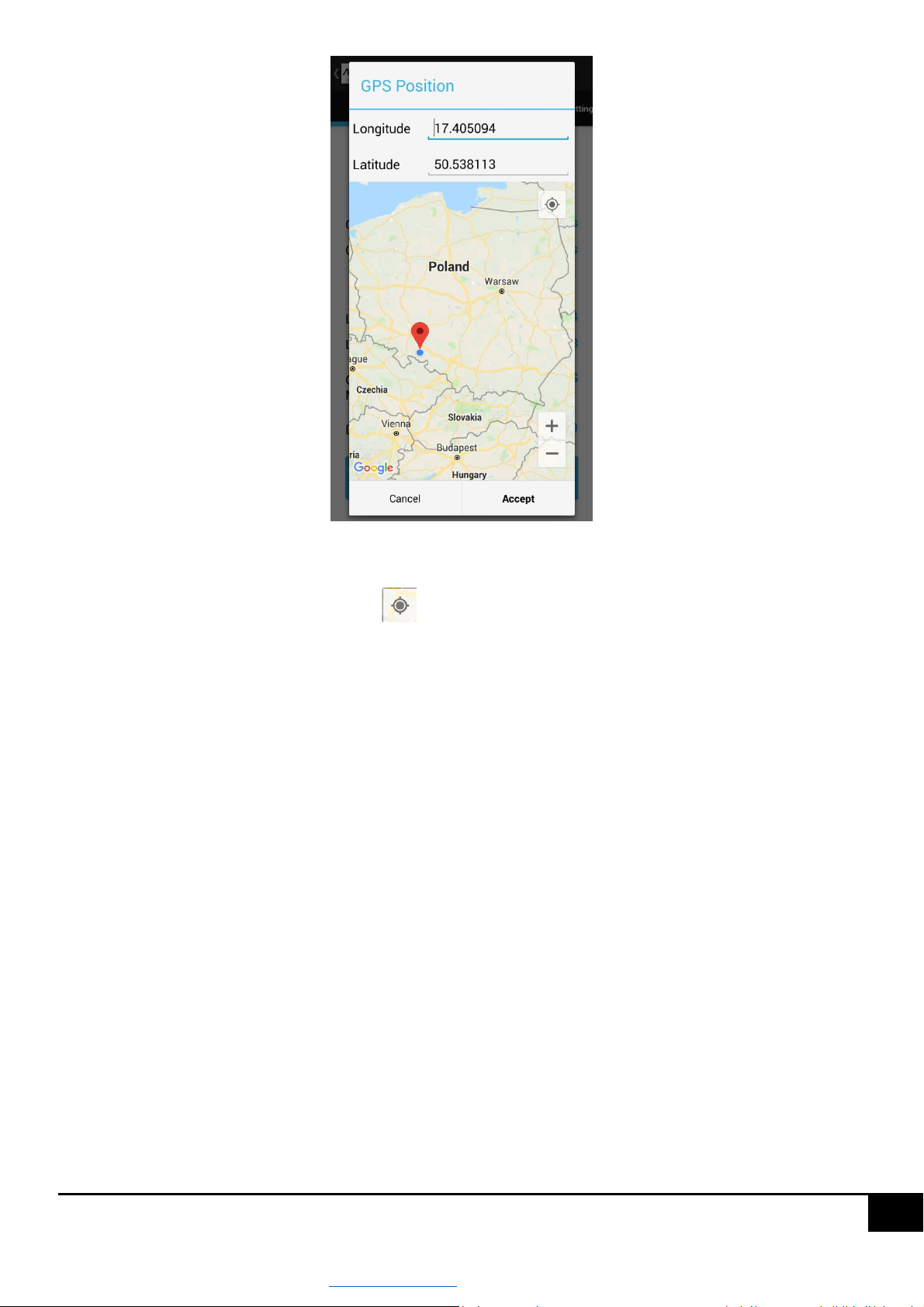
In order to change the position of the ASTmidi driver, on the "START" screen press one of the controller position values,
this will display a dialog box allowing you to enter the position, see figure below.
www.astsystem.pl | [email protected]
Page 15
15
There are three ways to enter a position:
By pressing the phone location button (usually located in the top right corner of the map). This will set
the position identical to the position of the phone, then press the "Set" button
By entering numeric values for the longitude and latitude of the driver and then pressing the "Set" button
Holding your finger at the current position of the marker will put it in a mobile state, after selecting the
appropriate place, press the "Set" button
CAUTION!!! - Astronomical switch-on and -off times of the outputs depend on the correct position of the driver.
5.5.3 Output operating time
The AST midi driver registers independently the switch-on time of the A, B and C outputs. Values of the outputs'
operating time can be found on the "START" screen. In order to reset the operating time of the outputs, press the time
value for the selected output, which will display a dialog box with information about the confirmation of the operation
of resetting the switching time for the selected output.
5.6 Output mode
The ASTmidi / ASTmidi GPS driver is equipped with two relay outputs with a NO contact. The A, B and C outputs are
programmable independently and can be in one of the four states:
AUTO – the output works automatically according to set intervals of switching on and off for each day of the
week.
www.astsystem.pl | [email protected]
Page 16
16
OFF – the output is permanently switched off and not subject to any control rule.
ON – the output is permanently switched on and not subject to any control rule.
It is switched on for a specified time, after which it switches to the AUTO status.
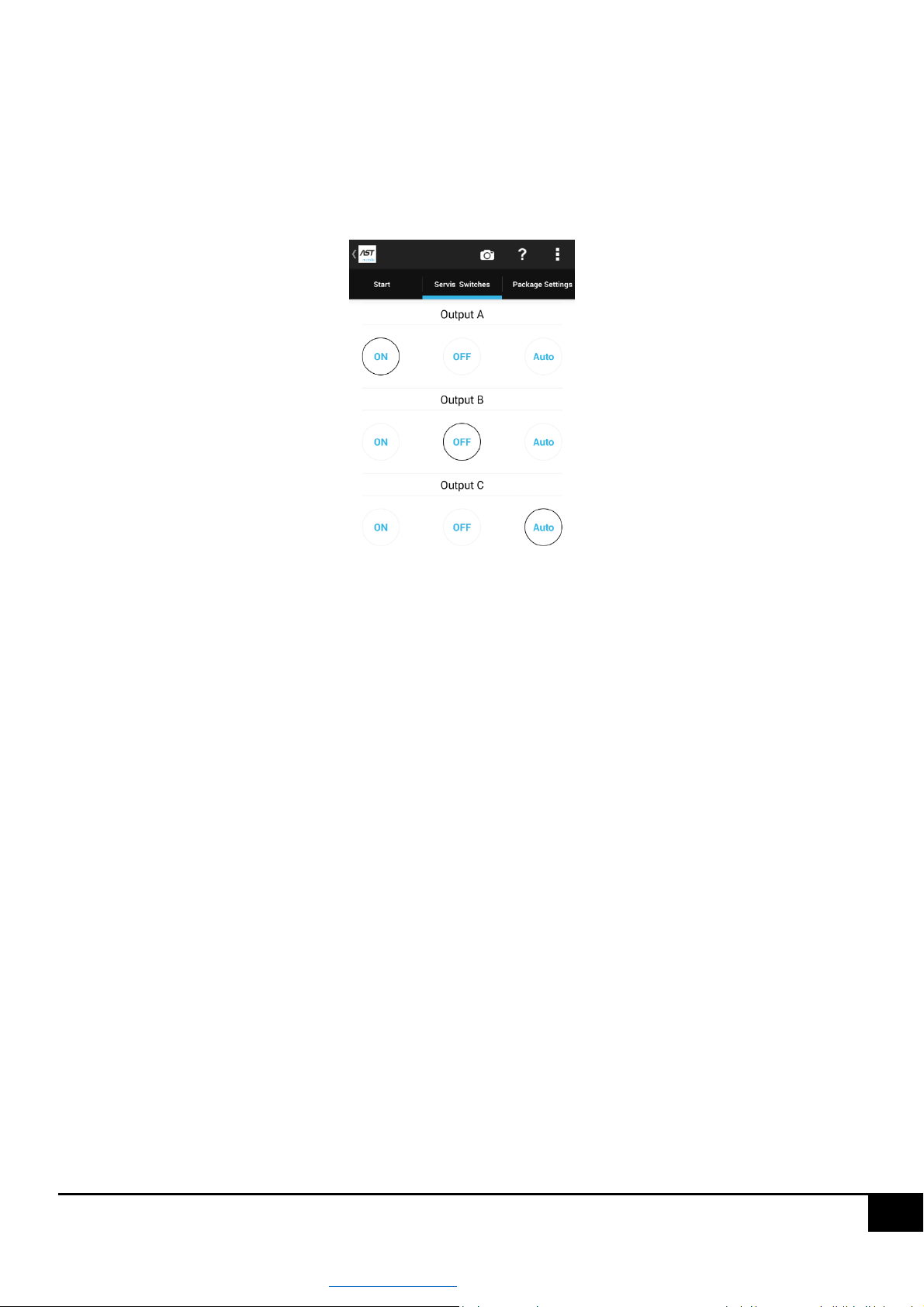
The output mode can be changed on the "Service connections" screen or on the "START" screen, if you have selected
a simplified view of the panel, see figure below.
A single pressing of the ON button will activate the output for 1 minute, double pressing will activate the output for
10 minutes, triple pressing will activate the output for 30 minutes, after that time the output will enter the AUTO
mode, while a quadruple pressing of the ON button will activate the output permanently and will not be subject to
any control rule.
Pressing the OFF button will switch off the output permanently.
For factory settings, outputs A and B operate in AUTO mode.
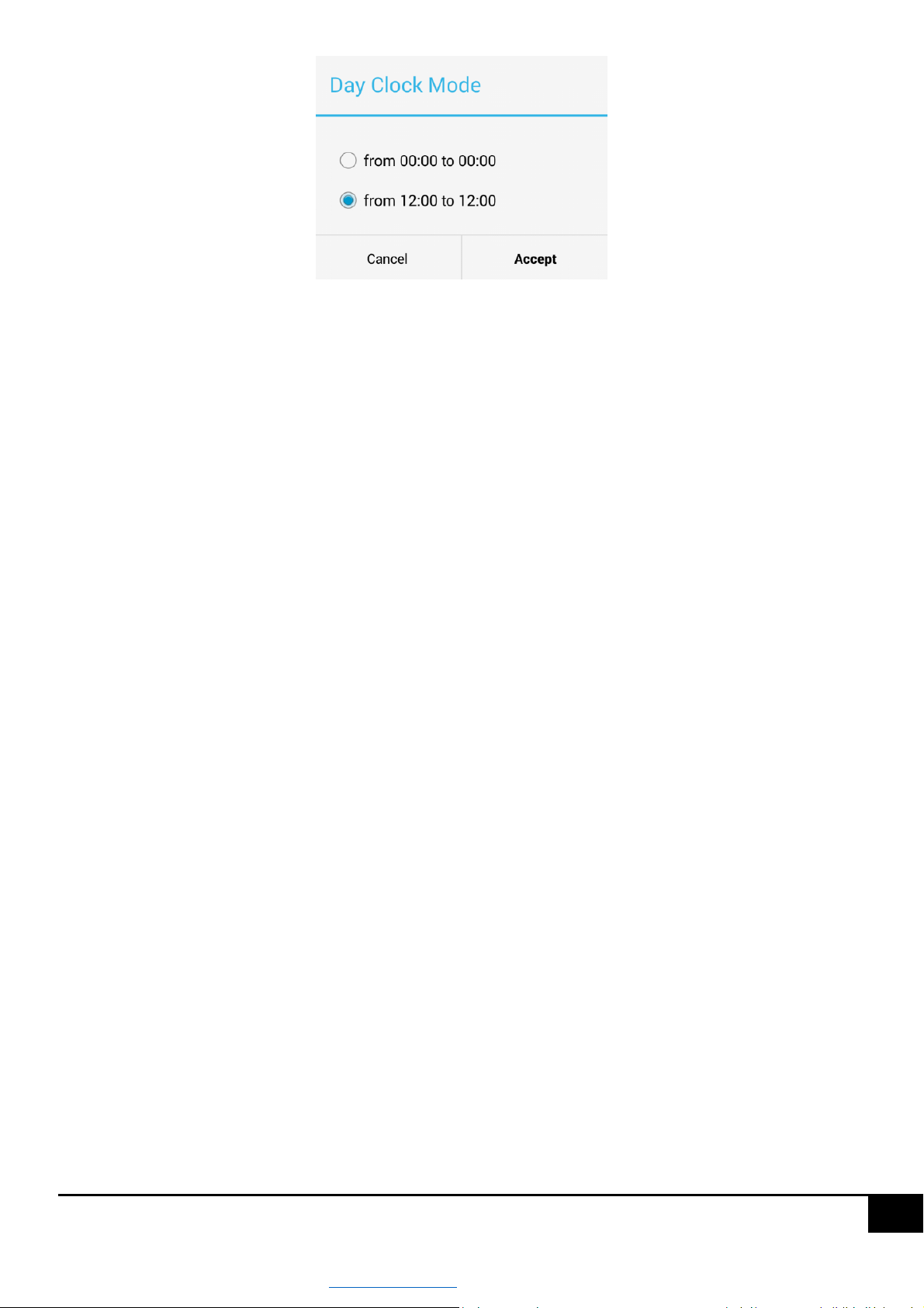
5.6.1 Day operation mode (lighting day / 24-hour day)
The ASTmidi / ASTmidi GPS driver can operate according to the 24-hour day (from 00:00:00 to 00:00:00:00) or the
lighting day (from 12:00:00 to 12:00:00:00). In order to change the type of day, select the day parameter on the
"START" screen, which will display a dialog box enabling the selection of the day, and a message informing that the
change of day will restore the switching intervals for the outputs A, B and C to their default values. In the case of a 24-
hour change from 00:00 to 00:00:00, the switch-on periods will be reset, i.e. the outputs will not be subject to any
control rule; in the case of a 24-hour change from 12:00 to 12:00, the intervals will be set. T1 start: Astro and T1 stop:
Astro, i.e. the outputs will be switched on at sunset and switched off at sunrise +- time adjustment, see figure below.
www.astsystem.pl | [email protected]
Page 17
17
24-hour day from 00:00 to 00:00:00 - selecting this item is recommended when most of the activities related
to switching intervals will take place during the day. If this item is selected, the switching interval must not
pass through 00:00:00.
Lighting day from 12:00 to 12:00 – selecting this item is recommended when most of the activities related to
switching intervals will take place in the night. If this item is selected, the switching interval must not pass
through 12 noon.
For factory settings the driver operates according to the lighting day.
For the lighting day (factory settings) T1 for outputs A, B and C is set as follows: T1 start: Astro and T1 stop: Astro, what
means that the outputs will be switched on at sunset +- adjustment time and switched off at sunrise.
After selecting a specific day, press the "Set" button to save the selection.
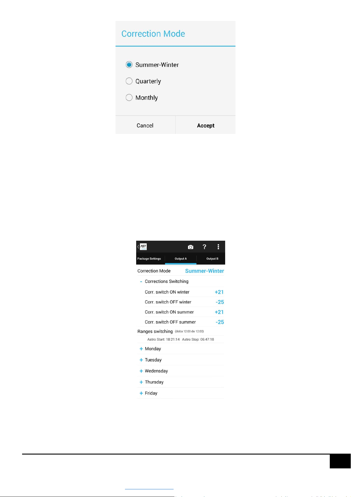
5.6.2 Correction mode
When the ASTmidi driver is used for lighting purposes and you use astronomical switch-on and switch-off times - these
times can be adjusted by means of corrections. In the driver three correction modes have been implemented:
Summer-winter - selecting this item will enable the correction of astronomical switch-on and switch-off times
independently in summer and winter time.
Quarterly - selecting this item will enable the correction of astronomical switch-on and switching-off times
independently in quarters I, II, III, IV.
Monthly - selecting this item will enable the correction of astronomical switch-on and switching-off times
independently in each month.
In order to change the correction mode, on the "Output A, B or C" screen select "Correction mode", what will display
a dialog box to perform this operation, see figure below.
www.astsystem.pl | [email protected]
Page 18
18
After selecting a specific value, press the "Set" button to confirm the change.
For factory settings the driver operates in the "Summer-Winter" mode. Correction values for factory settings
independently of the mode are: correction of switching on +15 minutes, correction of switching off -15 minutes.
5.6.3 Switching intervals
The ASTmidi / ASTmidi GPS driver allows you to enter up to four switching intervals for each day week independently
for outputs A, B and C. The switch-on periods can be configured from the "Input A, Output B and Output C" screens. A
view of the screen in the figure below.
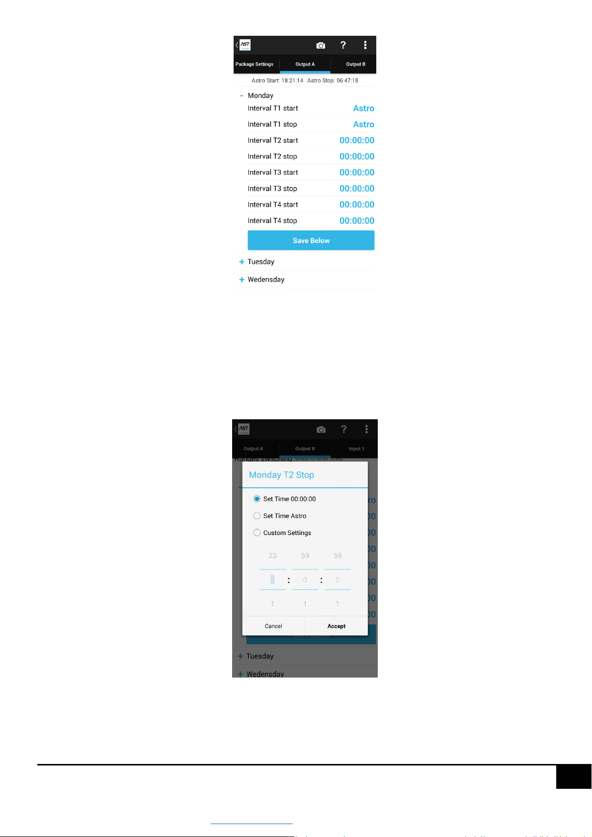
On this screen you can change the correction mode, correction values and set the appropriate switch-on intervals for
each day of the week. In order to change the switching range, expand the selected day by pressing the "+" button. The
appearance of the expanded panel is shown in the figure below.
www.astsystem.pl | [email protected]
Page 19
19
As you can see in the picture above, you can assign up to 4 switching intervals for each day, in the factory settings
there is only one T1 interval with T1 Start: Astro and T1 Stop: Astro settings used, which means that the output will be
switched on at sunset + switch-on time adjustment, and switched off at sunrise + switch-off time adjustment.
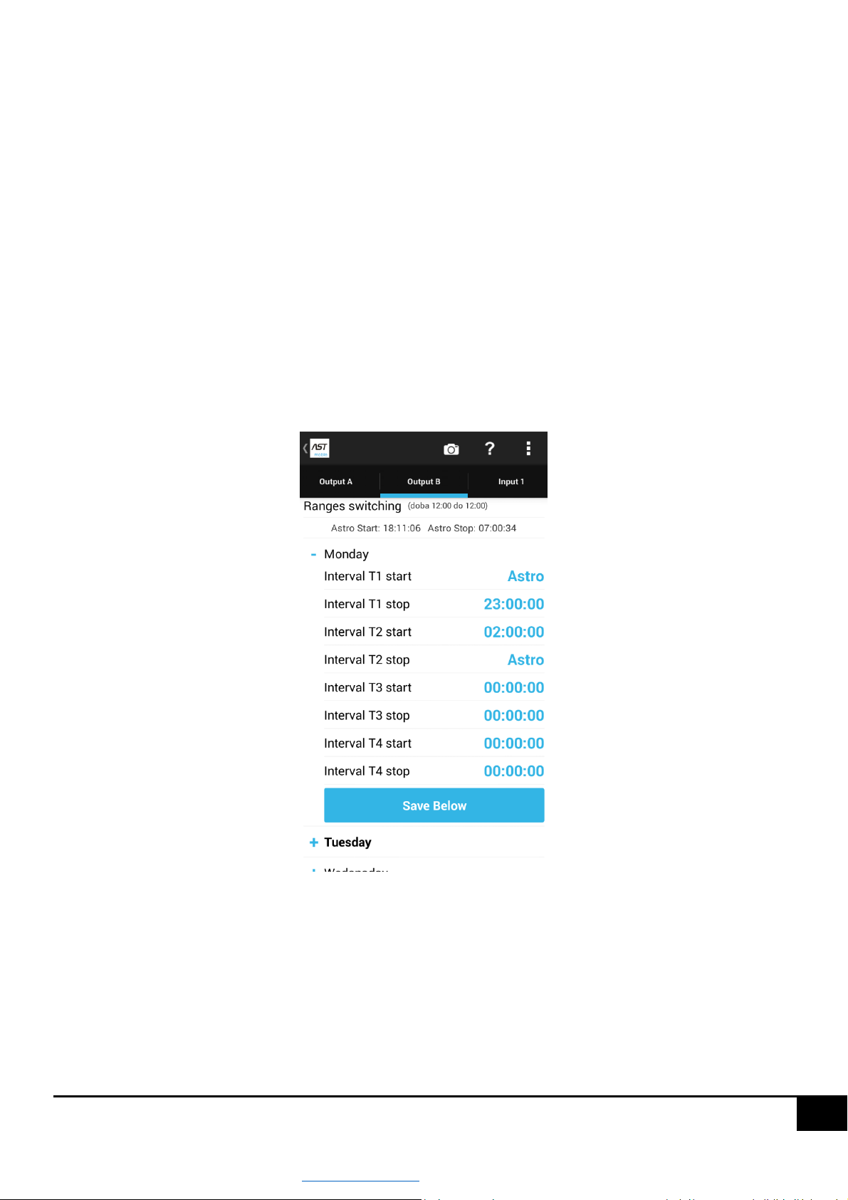
In order to change the switching interval, press on the selected interval, it will open the dialog window to change the
time value, see figure below.
Okno wprowadzania wartości przedziału zawiera trzy pozycje:
www.astsystem.pl | [email protected]
Page 20
20
Set 00:00:00:00 the time - selecting this item and pressing the "Set" button will set the time at 00:00:00:00,
setting this value for e.g. T1 start and T1 stop will mean that the interval is switched off.
Set the Astro time - selecting this item for T start means setting the astronomical switch-on time + switch-
on adjustment (this time has a different value each day, therefore it is displayed using an Astro prefix); if
you select this item for T stop, the astronomical switch-off time + switch-off adjustment will be set.
Custom settings - selection of this item allows you to set any time.
The following figure shows how to configure the switch-on intervals so that the output is switched on in the following
way:
1. switching on at sunset + correction
2. switching off 23:00:00
3. switching on 02:00:00
4. switching off at sunrise + correction
This type of setting in street lighting terminology means a night interruption from 23:00 to 02:00.
Of course, it is not necessary to use the "Astro" item in the switch-on intervals, any other value can be entered there
too.
CAUTION!!! Switch-off time interval must be larger than switch-on time interval, T start < T stop, in order to set to
the output on. Setting T start = T stop means that the interval is disabled.
www.astsystem.pl | [email protected]
Page 21
21
CAUTION!!! For 24-hour day from 12:00 to 12:00, the switch-on interval must not pass through 12:00 noon.
CAUTION!!! For a 24-hour day from 00:00 to 00:00 the interval must not go through 00:00 a.m., therefore for a day
from 00:00 a.m. to 00:00 a.m. one cannot set T start: Astro T stop: Astro
5.7 Input mode
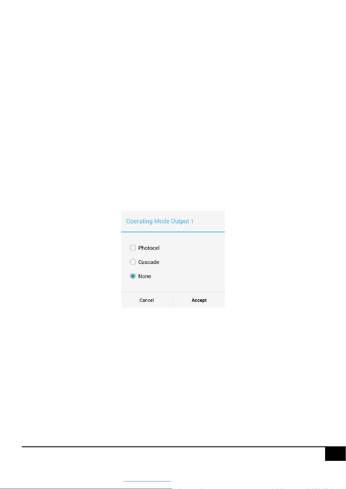
The ASTmidi / ASTmidi GPS driver has one input, which is a voltage input of 230V AC. The input can operate in one of
three modes:
Photocell – selecting this position means that the driver will analyze the state of the photocell plugged to
its input and on its basis it will correct the time of switching on of selected driver outputs.
Cascade – selecting this position means that the driver will transmit a signal from the driver input to
declared outputs of the driver in a possible delay function.
None – selecting this position means that the state of the input will not influence the state of driver
outputs in any way.
Changing the input mode can be done on the "Input 1" screen by pressing the "Input mode" position. This will display
the dialog box as shown in the figure below. After selecting a specific mode, press the "Set" button.
CAUTION!!! Regardless of the mode in which the input operates, a change of the input status is recorded in the
driver.
5.7.1 Photocell configuration
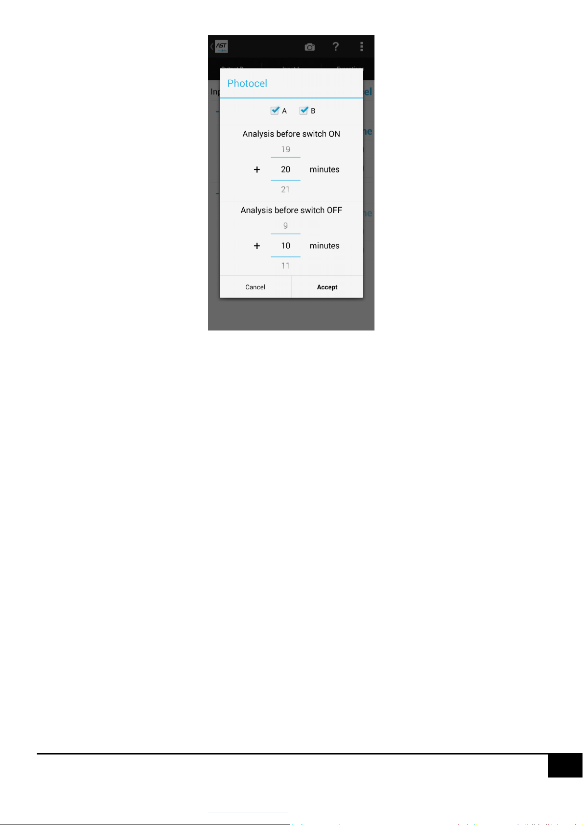
In case of selecting the mode of operation of the input as "Photocell" the next step should be to sett the rules for the
influence of the photocell on the status of the outputs. In order to configure the photocell, on the "Input 1" screen
press one of the photocell parameters to open the dialog box, see figure below.
www.astsystem.pl | [email protected]
Page 22
22
Three parameters must be set in this panel:
The output to be affected by the photocell (selectable from A, B, C, AB, AC, BC or ABC).
Analysis time before switch-on – this is the time before astronomical output switch-on, in which the driver
analyses the status of the input. For example, assuming that Astro switch-on time on a given day until 16:40:00
and the photocell is analyzed 15 minutes before switch-on, it means that the signal will appear at the driver
input from the photocell in the range from 16:25:00 to 16:40:00 and it will accelerate the activation of a
selected output.
Analysis time before switch-off – this is the time before astronomical output switch-off, in which the driver
analyses the status of the input. For example, assuming that Astro switch-off time on a given day is 04:40:00
and the photocell is analyzed 20 minutes before switch-off, it means that the loss of the photocell signal from
04:20:00 to 04:40:00 will accelerate the switch-off of a selected output.
After all parameters have been entered, press the "Set" button to confirm the changes.
5.7.2 Cascade configuration
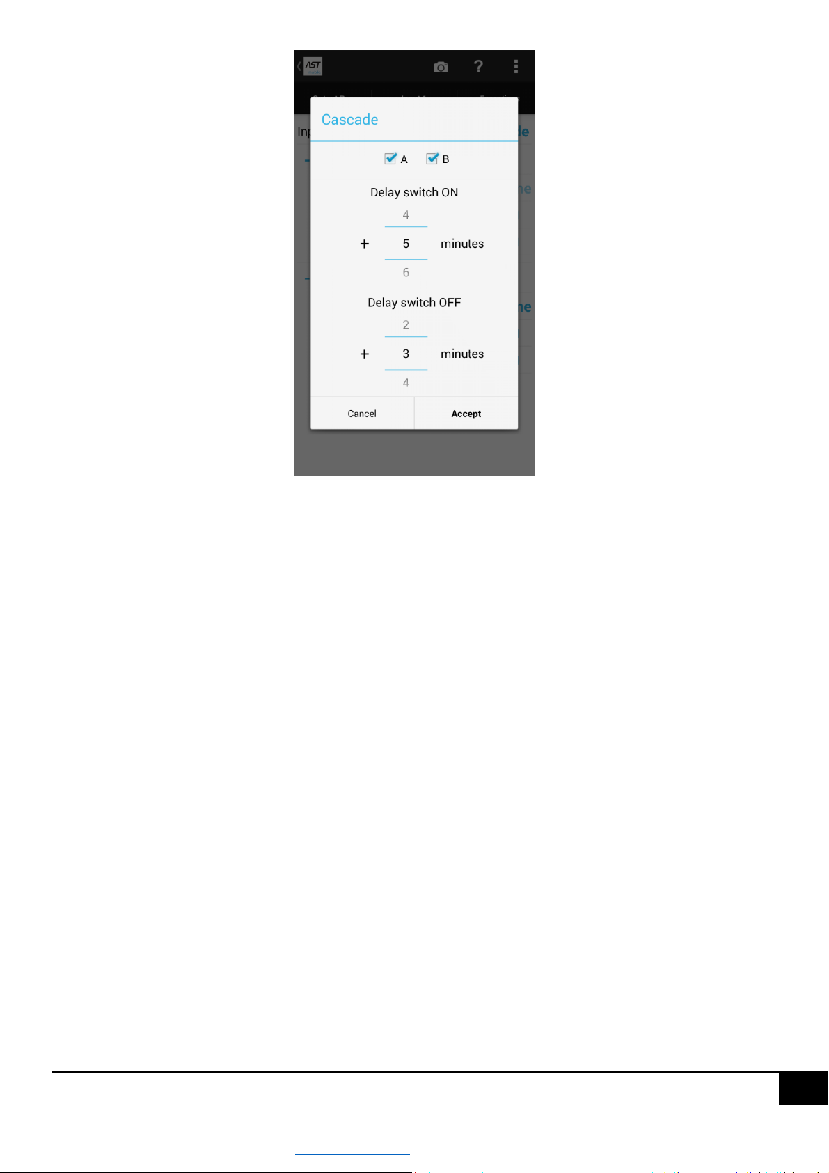
In case of selecting the input mode as "Cascade", the next step should be to set the rules of influence of the input state
on the output state. In order to configure the cascade, press one of the cascade parameters from the "Input 1" screen
to open the dialog window as shown below.
www.astsystem.pl | [email protected]
Page 23
23
Three parameters must be set in this panel:
Output which is to be affected by a signal at the driver input (selectable from A, B, C, AB, AC, BC or ABC).
Switch-on delay – this is the time from the moment the signal appears at the driver input, after which the
selected output will be switched on.
Switch-off delay – this is the time from the moment the signal at the driver input disappears, after which the
selected outputs will be switched off.
After entering all parameters, press the "Set" button in order to confirm the changes.
CAUTION!!! - If the input operates in the "Cascade" mode, the selected outputs are not subject to any other outputs.
rule of control, e.g. switching ranges.
5.8 Service switching
Service switch-on seen as the ASTmidi driver is a demanded switch-on of a selected output A, B or C.
The ASTmidi / ASTmidi GPS drivler is equipped with two relay outputs with a NO contact. Outputs A, B and C are
programmable independently and can be in one of four states:
AUTO – the output works automatically according to the set of switch-on and switch-off intervals for each day
of the week.
OFF – the output is permanently switched off, it is not subject to any control rules.
ON – the output is switched on permanently, it is not subject to any control rules.
www.astsystem.pl | [email protected]
Page 24
24
It is activated for a specified period of time, after which it switches to the AUTO state.
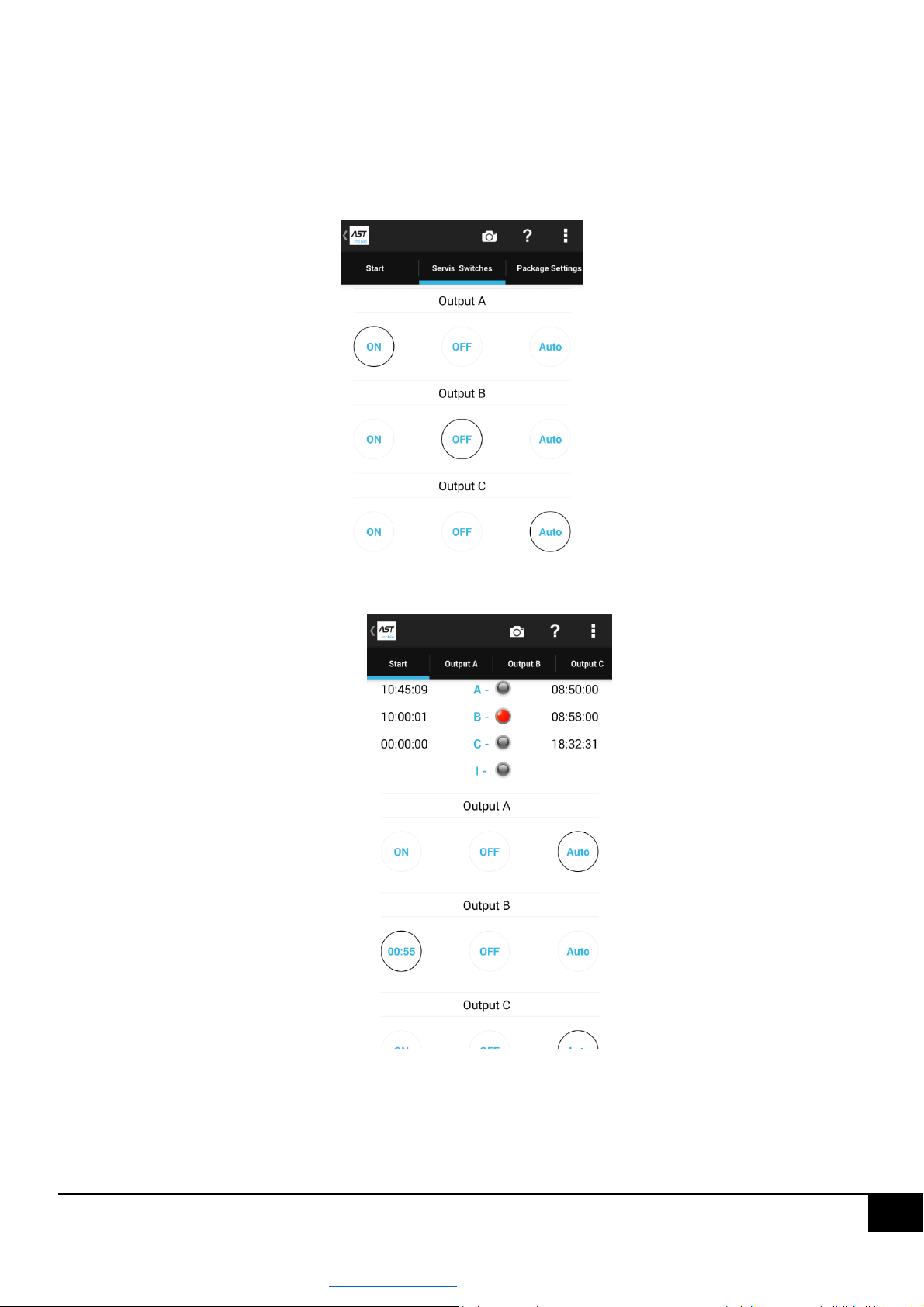
Service activation can be made on the "Service connections" screen or on the "START" screen, if you have selected a
simplified view of the panel, see drawing below.
Service activation on the "Service activation" screen.
Service activation on the "Start" screen.
www.astsystem.pl | [email protected]
Page 25
25
Scenarios of using service interruptions:
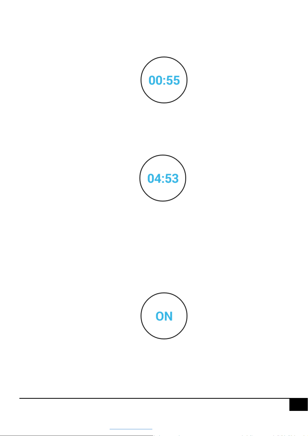
In order to switch on a service output, e.g. A for 1 minute, press the ON button once, which will display on
this button a countdown time of 1 minute, see picture below.
Output A will be switched on for 1 minute and after this time will go to automatic operation.
In order to switch on output A for 10 minutes, press the ON button twice, which will display on this button a
countdown time of 10 minutes, see picture below.
Output A will be activated for 10 minutes and after this time will switch to automatic operation.
In the same way the output can be switched on for 30 minutes.
CAUTION!!! Service switch-on of the outputs is a very convenient tool during service or start-up operations. The
service switch-on guarantees that after a specified time it will go into automatic operation.
In order to switch on the output permanently, press the ON button four times, it will illuminate this button as
in the picture below.
After performing this action, the output will be permanently activated until further notice.
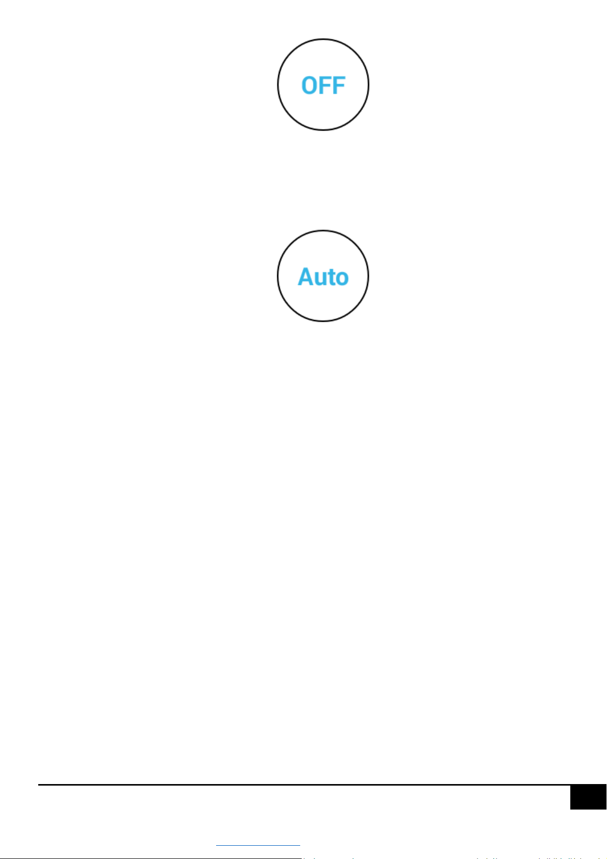
In order to switch off the output permanently, press the OFF button, it will illuminate this button as in the
figure below.
www.astsystem.pl | [email protected]
Page 26
26
After performing this operation, the output will be turned off until further notice.
To enter the automatic mode, press the AUTO button to illuminate this button as shown in the figure below.
After performing this operation, the output will operate automatically according to the set switch-on intervals for
each day of the week.
CAUTION!!! If the output is permanently switched on or off, it is not subject to any control rules, in order for the
output to start working automatically press the AUTO button on the selected output.
www.astsystem.pl | [email protected]
Page 27
27
5.9 Exceptions
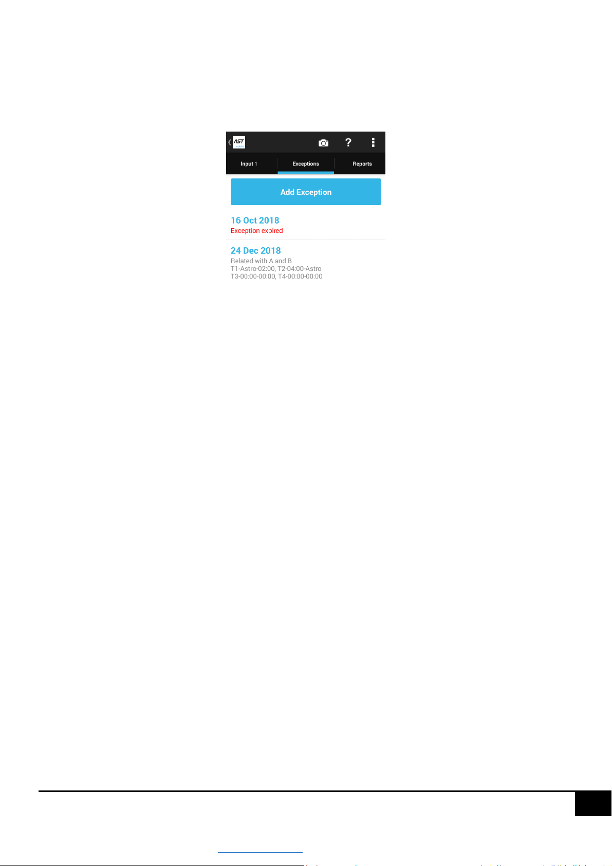
Up to 20 switching exceptions can be entered in the ASTmidi driver. The exception for ASTmidi driver should be
understood as a set of switch-on intervals that will be used for a specific date. Exceptions that are entered into the
driver can be seen from the ASTmobile application - "Exceptions" screen, figure below.
The exception, which is beyond the date of occurrence is marked as "Exception expired”.
You can perform three operations on exceptions:
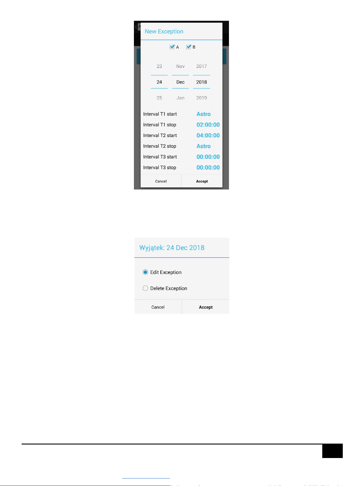
Add exception – in order to do so, press the "Add exception" button to open a dialog box where you can
specify exception parameters such as:
1. 1. Specify the outputs with which the exception is associated.
2. 2. Specify the date of occurrence of the exception.
3. 3. Specify switch-on intervals – switch-on intervals are defined in the same way as switch-on intervals for
outputs A, B and C.
The view of the Add Exception window is shown in the figure below.
www.astsystem.pl | [email protected]
Page 28
28
After entering all parameters, press the "Accept" button to add an exception.
Edit exception – in order to edit an exception press on the selected exception to open the dialog window as in
the figure below.
Then select "Edit exception" to open a window identical to the case of adding a new exception, after modifying
the parameters of the exception press the "Accept" button.
Delete exception – in order to delete an exception press the selected exception. This will open a dialog
window, in which you should select the item "Delete exception" and press the button "Accept”.
5.10 Recording events
The ASTmidi / ASTmidi GPS driver can record up to 600 events. The following events are recorded:
Power failure.
Return to power supply.
Switching on output A.
www.astsystem.pl | [email protected]
Page 29
29
Switching off output A.
Switching on output B.
Switching off output B.
Switching on output C.
Switching off output C.
Appearance of 230V AC signal at Input I.
Appearance of 230V AC signal at Input I.
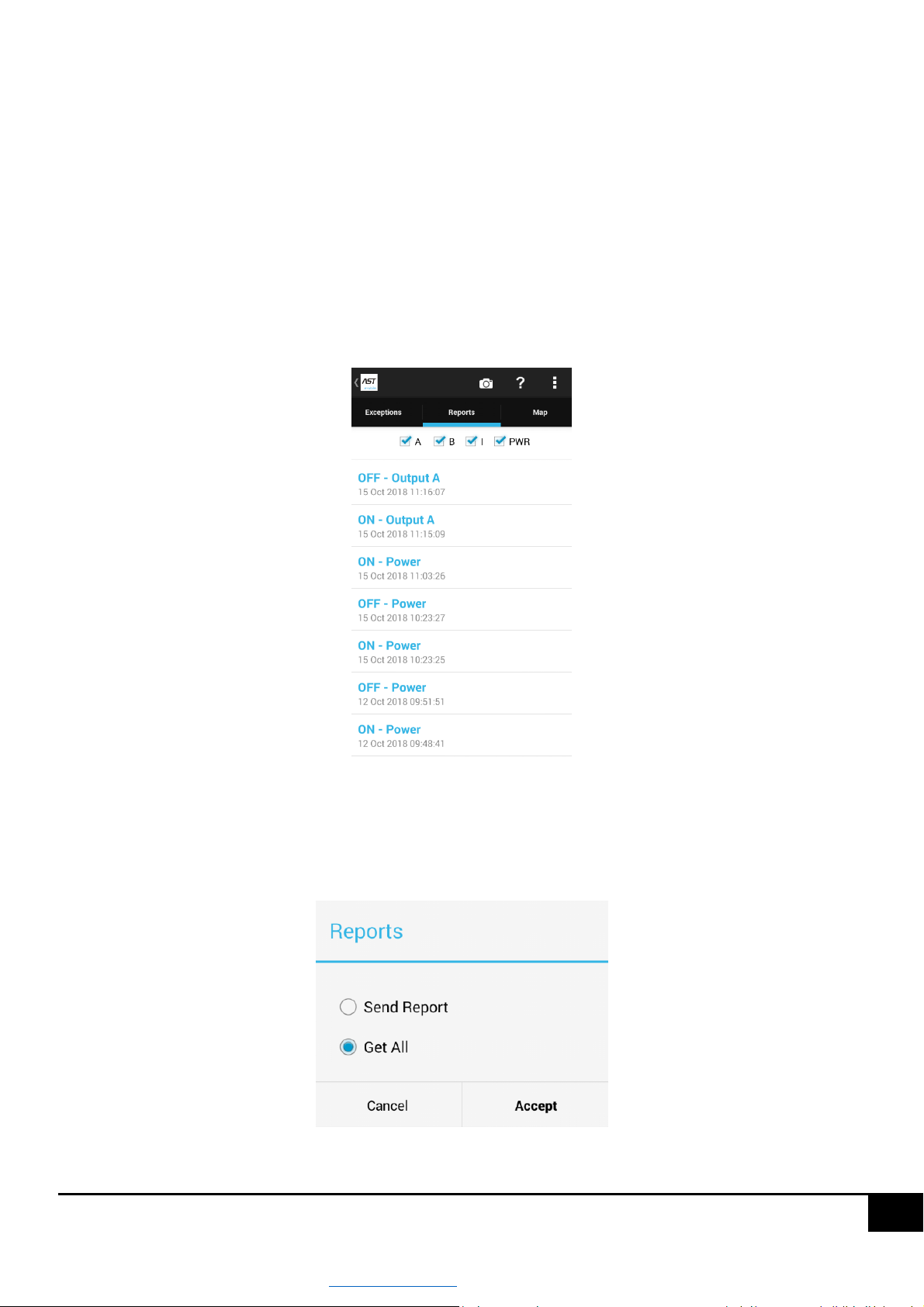
Events are saved with exact date and time of occurrence, and can be viewed using ASTmobile application from the
"Reports" screen, see figure below.
This screen contains a list of all recorded events, at the top of the screen by unchecking / selecting A, B, C, I and PWR
(Power). You can filter displayed records.
Pressing any event will display a dialog box as shown in the figure below. It will be presented with two items:
www.astsystem.pl | [email protected]
Page 30
30
Send a report – selecting this item and pressing the "Execute" button will enable sending a report (recorded
event) e.g. via e-mail, MMS, SMS, etc.
Download all – selecting this item and pressing the "Execute" button will download all events from the driver.
5.11 Replacement of internal driver software
The AST System company is constantly developing its products, so in each of our solutions there is a possibility of a
remote exchange of the software. In the ASTmidi / ASTmidi GPS, the internal software of the driver can be
exchanged wirelessly using the ASTmobile application.
If new functionalities are introduced to the ASTmidi / ASTmidi GPS driver, an update of the ASTmobile application
will be published in Google Play, including a new version of the driver software. Then you should update the
ASTmobile application (very often the updates are installed automatically), run the application and connect to your
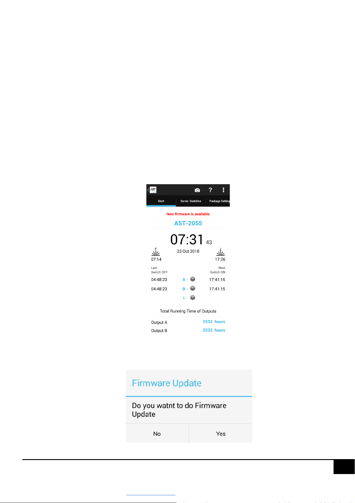
driver. If the application detects that the driver has older software, a message "A new firmware version is available"
will be displayed on the "Start" screen, as shown in figure below.
Then you should click on this message to display a dialog box with information that if you want to update the driver
software, (figure below). Pressing the "Yes" button will start the process of software replacement.
www.astsystem.pl | [email protected]
Page 31
31
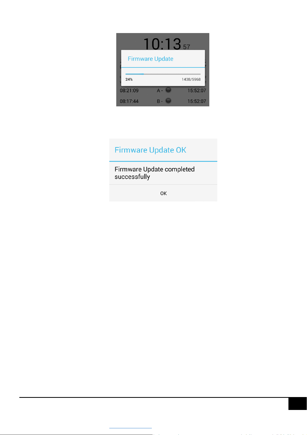
The progress of software replacement will be indicated by the progress bar, figure below.
After the software replacement is finished, a message about correctness or problems with software replacement will
be displayed, see figure below.
After correct software replacement, press the "OK" button to move the application to the search screen for available
ASTmidi drivers, after searching for the driver again, you can connect to it, and a message about availability of a new
software version should disappear from the start screen.
In case of unsuccessful software replacement, the software replacement operation should be repeated.
CAUTION!!! During the software replacement process, do not disconnect the power supply from the driver and be
in close proximity to the driver in order to ensure good range.
CAUTION!!! In case of a power failure during the software replacement process or loss of range between the
controller and the phone, the replacement process will fail, the last software version will remain in the driver. There
is no risk of damaging the driver during software replacement, due to e.g. power failure during the replacement
process or loss of range.
5.12 Factory settings
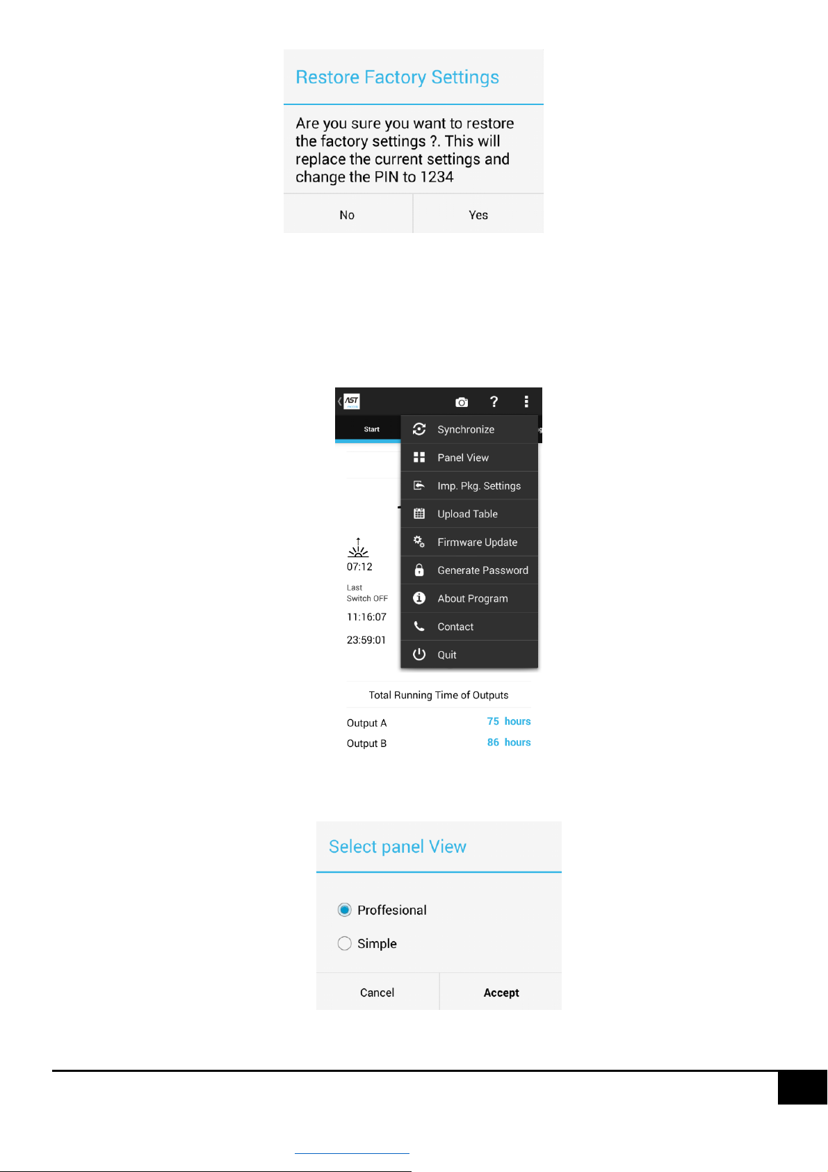
In order to restore factory settings of the driver, on the "Start" screen press the "Restore factory settings" button
located at the very bottom of the "Start" screen. This will display a message to confirm the operation, see figure below.
Pressing the "Yes" button will restore factory settings - all driver settings will be replaced with factory settings.
www.astsystem.pl | [email protected]
Page 32
32
Factory settings can be restored on the "Start" screen only when the application panel view is "Professional”.
To change the panel view, proceed as follows:
Expand the application menu by pressing the three squares in the upper right corner of the application, see
figure below.
Select "View panel", this will display a dialog box as shown in the figure below, and then select "Professional"
and press the "Set" button.
www.astsystem.pl | [email protected]
 Loading...