

Page 1
MA214-20180119 Rev. C.2 Copyright © 2018 by Ballard Technology, Inc.
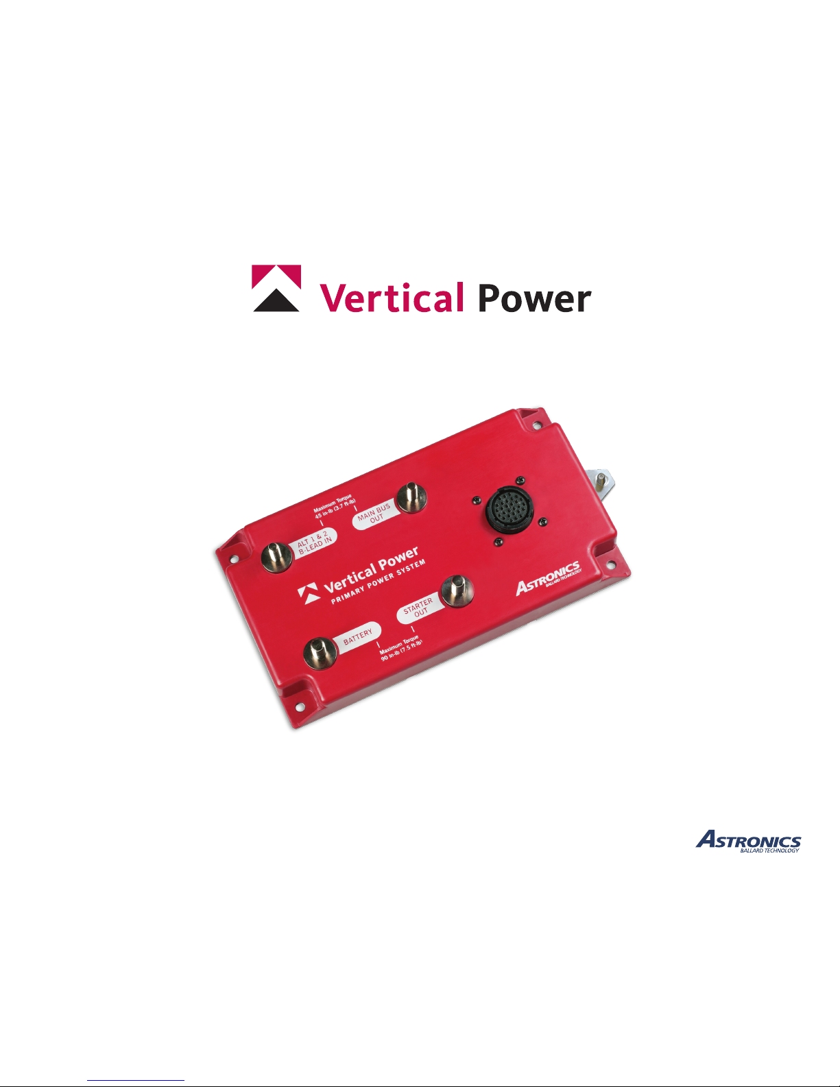
Primary Power System (PPS)
Primary power control for experimental and light-sport aircraft
Installation and Operating Manual
January 19, 2018
Rev. C.2
Page 2

PPS Installation and Operating Manual
Rev. C.2 (January 19, 2018)
Table of Contents
1. Introduction
1.1 PPS Overview ............................................1
1.2 Reference Numbers .......................................1
1.3 Terms and Denitions ......................................1
1.4 Other Documentation ......................................2
2. Operation
2.1 Main Bus Contactor .......................................2
2.2 Alternator Contactor .......................................3
2.3 Main Starter Contactor .....................................3
2.4 Control / Status ...........................................3
2.4a Control Inputs .......................................3
2.4b Status Outputs .......................................4
3. Electrical System Basics
3.1 Free advice on Designing your Electrical System ................5
3.2 Basic Concepts ...........................................6
3.3 Alternator Options ........................................6
3.4 Wire Sizes and Circuit Protection .............................7
3.5 Grounding - IMPORTANT ..................................7
3.6 Switch Nomenclature ......................................8
3.7 Current Sensing (Shunt) ....................................8
4. Installation and Test
4.1 Planning ................................................9
4.1a Tools and Supplies ....................................9
4.1b Wiring Diagrams .....................................9
4.2 Installation .............................................13
4.2a Mount the PPS ......................................13
4.2b Terminal Wiring .....................................15
4.2c Control/Status Wiring ................................ 15
4.3 Ground Test .............................................16
4.3a Ground Test without engine running .....................16
4.3b Start Mode Duty Cycle ...............................16
4.3c Ground Test with engine running ........................17
4.4 Flight Test ..............................................17
5. Maintenance
5.1 Do’s and Don’ts .........................................18
6. Troubleshooting
6.1 Common Problems .......................................18
7. Specications
7.1 General ................................................19
7.2 Circuit Ratings ..........................................19
7.3 Environmental / Physical ..................................19
Page 3

PPS Installation and Operating Manual
Rev. C.2 (January 19, 2018)
Important Notice
This manual contains important information that may affect the safety of your aircraft. Do
not y the aircraft until you fully understand the installation and operating instructions,
and all of the pre-ight checks have been successfully completed.
Read the Limited Warranty (document number AD263 Limited Warranty Vertical Power Product
Line) available at www.verticalpower.com. There is information in the Limited Warranty that
may alter your decision to install this product. If you do not accept the terms of the Limited
Warranty, do not install this product. The product may be returned for a refund if you do not
accept the terms of the Limited Warranty.
Ballard Technology, Inc. is not liable or responsible for a pilot’s action or any situation that
results in personal injury, property damage, missed commitments, lack of use of an aircraft
or any expenses incurred due to: product failure, inaccuracy in displayed data or text les,
display or display format issues, software bugs or problems, upgrade or customization
issues, misinterpretation of the display, warning and/or limit settings, calibration problems,
installation issues (leaks, mis-wiring, obstructions, damage to aircraft or components, incorrect
installation of any parts, wrong parts, parts that don’t t, etc.) or any other issues related to the
installation or operation of this product. All of the above are solely the pilot’s and/or installer’s
responsibility.
The pilot must understand the operation of this product before ying the aircraft. The pilot
will not allow anyone to operate the aircraft that does not know the operation of this product.
The pilot will keep the PPS Operating Instructions in the aircraft at all times. The ability for this
product to correctly control electronic components and detect a problem is directly related to the
pilot’s ability to properly install the system, and the pilot’s interpretation and observation skills.
By installing this product, the aircraft owner/pilot and installer agree to hold Ballard
Technology, Inc. harmless and in no way responsible for monetary compensation, including
punitive damages for any incident, harm and/or damage associated with this product (including
but not limited to the ones listed above). If you do not agree to the above, DO NOT INSTALL
THIS PRODUCT. The pilot, aircraft owner and/or installer may want to obtain an appropriate
insurance policy before installing this product. If you do not have the skills, knowledge, tools,
equipment or facility, to perform and determine the installation of this product is safe, reliable
and accurate and to determine this product is operating properly after installation, DO NOT
INSTALL THIS PRODUCT. If the aircraft owner/pilot and/or installer are unwilling to take
the responsibility for the installation and operation of this product, DO NOT INSTALL THIS
PRODUCT. This product may be returned for a refund by contacting Ballard Technology, Inc.
It is possible for any system to fail thereby disabling electronic components or displaying
inaccurate high, low or jumpy readings. Therefore, you must be able to recognize a system
failure and you must be procient in operating your aircraft safely in spite of a system failure.
IT IS THE BUILDER AND/OR PILOT’S RESPONSIBILITY TO DETERMINE THE
APPROPRIATE LEVEL OF BACKUP AND REDUNDANT SYSTEMS NEEDED FOR
SAFE OPERATION OF THE AIRCRAFT. If you do not have this knowledge or skill, contact
the FAA, a certied aircraft mechanic, or a local ight instructor for training prior to building or
ying the aircraft with this system.
Before ying the aircraft verify the instrument markings displayed on the system are accurate
with your POH for every function displayed. Verify that each electrical device is congured
correctly and behaves appropriately. All data must be veried by the pilot before it is used.
Before starting the installation, make sure that your planned installation will not interfere
with the proper operation of any controls. The installer should use current aircraft standards
and practices to install this product. Refer to AC 43.13-2A, Acceptable Methods, Techniques,
and Practices - Aircraft Alterations and AC 43.13-1B, Acceptable Methods, Techniques, and
Practices—Aircraft Inspection and Repair.
The PPS is an experimental system limited to use in experimental aircraft or Light Sport
Aircraft. PPS products are not approved for use in aircraft with FAA or foreign type certicates.
Limited Warranty
For Warranty information, please refer to document number AD263 Limited Warranty Vertical
Power Product Line available at www.verticalpower.com/documents.
Copyright Notice
Copyright ©2018 by Ballard Technology, Inc. Ballard Technology’s permission to copy and
distribute this manual is for the purchaser’s private use only and is conditioned upon purchaser’s
use and application with the hardware that was shipped with this manual. No commercial resale
or outside distribution rights are allowed by this notice. This material remains the property of
Ballard Technology. All other rights reserved by Ballard Technology, Inc.
Trademarks
Vertical Power is a registered trademark of Ballard Technology, Inc. All other product names or
trademarks are property of their respective owners.
Astronics Ballard Technology
11400 Airport Road
Everett, WA 98204
Phone: 425.328.1658
Fax: 425.339.0915
Email: [email protected]
Page 4

PPS Installation and Operating Manual
Rev. C.2 (January 19, 2018)
Change Log
Change date Change
Oct 21, 2015 Initial public release
Mar 29, 2017 Updates based on product changes incl. new pinouts
Aug 24, 2017 Updated grounding instructions
Sep 25, 2017 Updated grounding diagram and Table 4.2b
Jan 19, 2018 Updated current values; added Start Mode Duty Cycle
information; added GND stud and grounding updates
to tables, diagrams and drawings; added maintenance
recommendations.
Page 5
Page 1
PPS Installation and Operating Manual
Rev. C.2 (January 19, 2018)
1. Introduction
This manual is the user’s guide for the Vertical Power Primary Power
System (PPS). The PPS is a new and innovative way to simplify wiring
on your aircraft. It replaces a host of mechanical components with solidstate circuits.
While the PPS makes life easier for the builder, it’s not simply a plugand-play solution. The builder must still run wires to electricallypowered components and this wiring takes some careful planning. Please
take the time to read and understand this manual before proceeding.
This manual describes the steps and techniques necessary to install and
operate the PPS.
1.1 PPS Overview
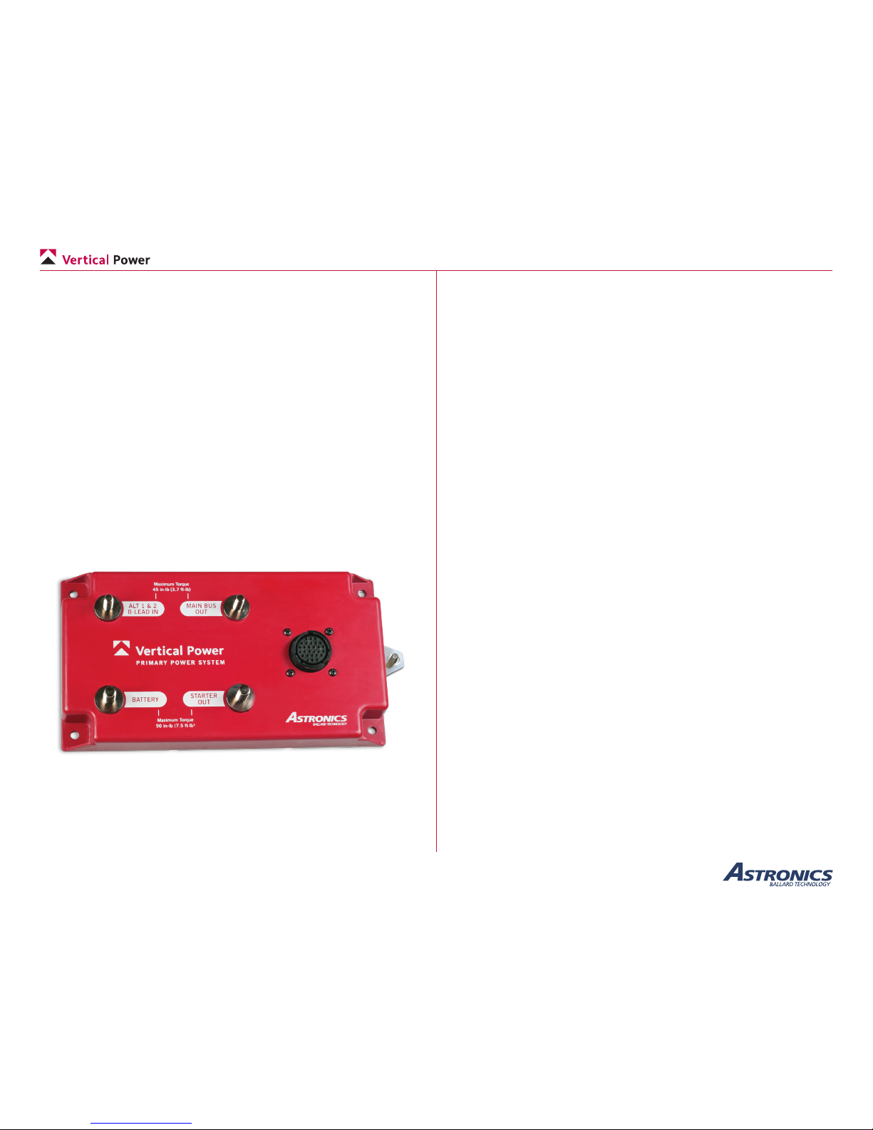
The PPS controls power from the battery to the starter and the main bus.
It also ties into the alternator b-lead(s) so that alternator power can both
charge the battery and provide power to the main bus.
The Vertical Power PPS
The PPS works with a single-bus architecture. It supports a single battery
and one or two alternators. Additional small backup batteries and E-Bus
circuits can be tied into the PPS via the battery terminal.
It does not implement a true dual-bus architecture (two independent
batteries, alternators, battery contactors, and a cross-tie contactor).
Multiple PPS units can be used to implement a dual-bus architecture.
Please contact support for more information on dual-bus installations.
The system also works with rear-mounted batteries, as shown in one of
the wiring diagrams later in the manual.
The PPS is designed to ‘t in’ with the way master switches and starter
switches are normally wired. No special wiring or provisions are needed.
The PPS also includes fault outputs that show you when the alternator or
main bus line have faulted.
1.2 Reference Numbers
For future reference, we encourage you to record the model number
and serial number of your PPS product. You may wish to use the space
provided below:
Model No: __________________
Serial No: __________________
1.3 Terms and Denitions
Device A user of electrical power. It may be a light, radio,
GPS receiver, contactor, or EFIS, just to name a few. A
device is wired to a power pin on the VP-X.
Pin A pin refers to a physical pin on the connector.
ECB Electronic circuit breaker. A solid-state, circuit
protection module used inside the PPS.
Connector The Primary Power System uses a 28-pin circular
plastic connector for J1. It is made by TE Connectivity.
A mating connector of the same brand is recommended
for compatibility.
AWG American Wire Gauge – a standard that describes the
size of the wire.
Page 6
Page 2
PPS Installation and Operating Manual
Rev. C.2 (January 19, 2018)
Circuit breaker While the PPS does not use conventional circuit
breakers or fuses, the term is very common and herein
is used to mean the maximum current a circuit will
draw before faulting.
Fault The PPS protects the alternator b-lead and main bus
wires. When a fault occurs, the PPS turn on the fault
light. You can then reset or clear the fault, similar to
resetting a circuit breaker.
1.4 Other Documentation
We provide other documents that should be used in conjunction with this
manual to help you thoroughly plan a safe and effective electrical system
for the type of mission you y. The following documents are available on
the Documents page in the Help section of the Vertical Power web site
(www.VerticalPower.com), and should be reviewed in conjunction with
planning your electrical system.
Document Description
Contactor Wiring Overview of the different types of contactors
used in experimental aircraft, and step by
step instructions how to wire them properly.
Device Amps This document lists the electrical current
draw of many popular radios, GPS moving
maps, EFIS displays, lights, and other
avionics. We maintain it, but contributions
come from builders.
Top 10 Wiring Mistakes A free, 12-page paper describing the most
common wiring mistakes and how to get
started wiring your aircraft.
Additional documentation may also be available on the web site.
2. Operation
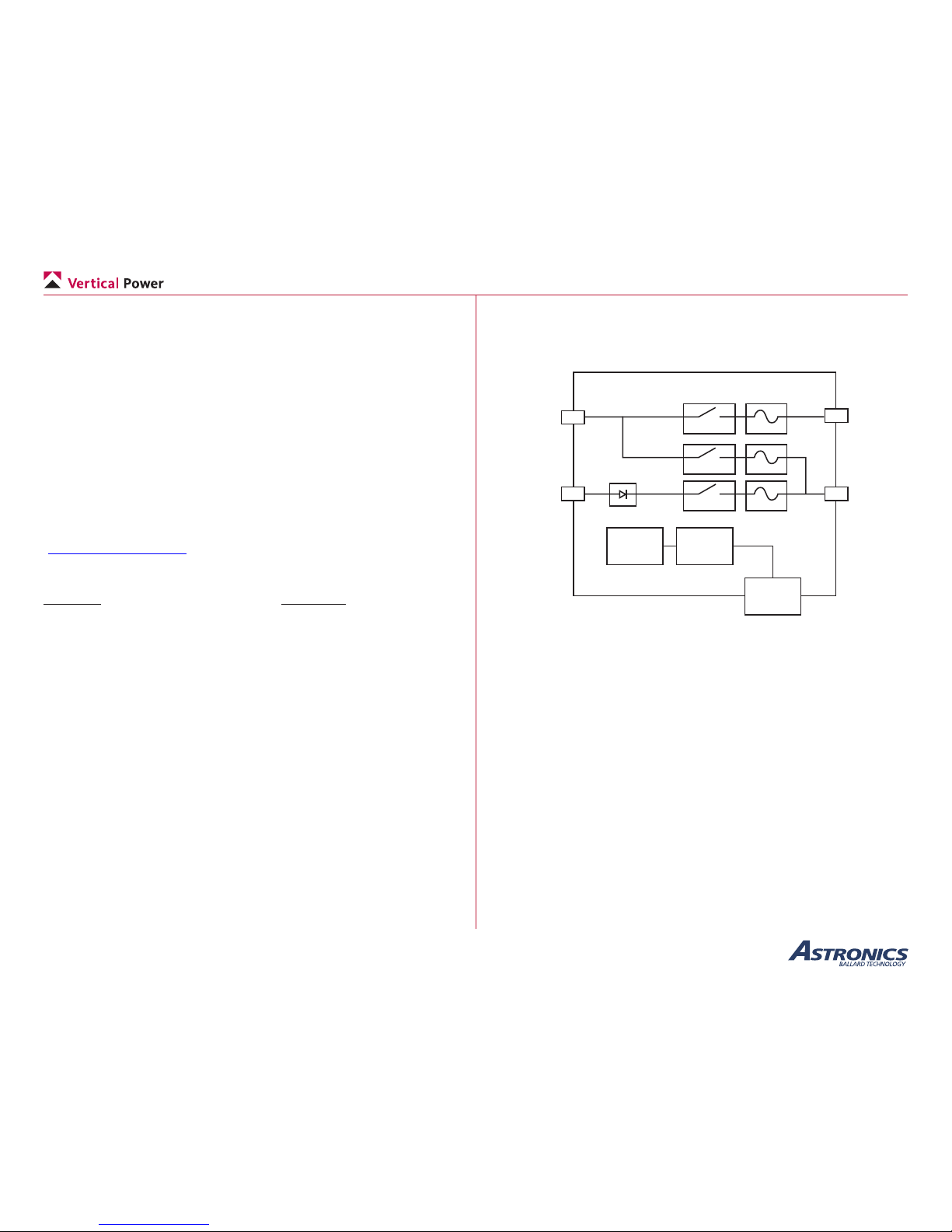
The functional block diagram of the PPS is shown below. The following
sections explain in detail how each functional block of the PPS operates.
28-pin
Circular
Connector
Power
Supply
300 A
80 A
80 A
Reverse
Protection
Fault
Detection/
Control
Main
Bus
Out
or Main
Power
Starter
Out
Alt 1 & 2
B-Lead
In
Main
Battery
The Functional Block Diagram of the PPS
2.1 Main Bus Contactor
The main bus contactor allows current to ow to/from the main battery to
the main power bus. This allows the battery to provide power to the main
power bus loads and battery charging once the alternator is powering the
main bus.
For the contactor to be closed, the master switch (MASTER) must be
closed, the main battery (BATT DIST EN) must be enabled, and there
must not be an active fault.
The main bus contactor will latch open and indicate a fault (BATT DIST
FAULT) if the slow-trip current or the instantaneous maximum current of
320 amps is exceeded. The slow-trip current emulates the trip curve for a
standard 80 amp slow-blow fuse.
The main bus contactor fault may be reset by either toggling the main
battery (BATT DIST EN) or master switch (MASTER).
Page 7
Page 3
PPS Installation and Operating Manual
Rev. C.2 (January 19, 2018)
2.2 Alternator Contactor
The alternator contactor allows current to ow from the alternator(s)
to the main power bus. This allows one or more alternators to provide
power to the main power bus loads and battery charging if the main bus
contactor is closed.
For the contactor to be closed, the master switch (MASTER) must be
closed, the alternator (ALT DIST EN) must be enabled, and there must
not be an active fault.
The alternator contactor will latch open and indicate a fault (BATT DIST
FAULT) if the slow-trip current or the instantaneous maximum current of
400 amps is exceeded. The slow-trip current emulates the trip curve for a
standard 100 amp slow-blow fuse.
The alternator contactor fault may be reset by either toggling the
alternator (ALT DIST EN) or master switch (MASTER).
2.3 Main Starter Contactor
The main starter contactor allows current to ow from the main battery
to the starter.
For the contactor to be closed, the master switch (MASTER) must be
closed, the main starter (MAIN BATT START EN) must be enabled, and
there must not be an active fault.
The starter active indicator (STARTER ACTIVE) will be active when
there is voltage present at the starter output regardless of the main starter
contactor or auxiliary starter contactor being closed.
The main starter contactor will latch open if the slow-trip current, the
fast-trip current of 1200 amps or the instantaneous maximum current of
1500 amps is exceeded. The slow-trip current emulates the trip curve for
a standard 300 amp slow-blow fuse.
The main starter contactor fault may be reset by toggling the main starter
(MAIN BATT START EN) or master switch (MASTER).
2.4 Control / Status
2.4a Control Inputs
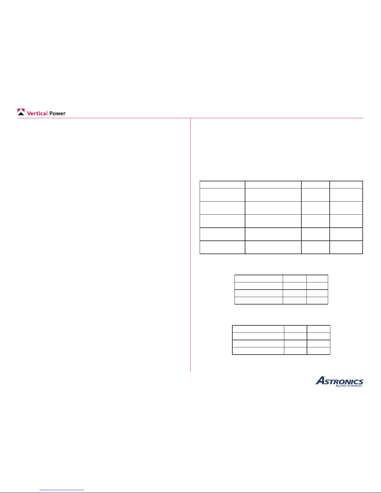
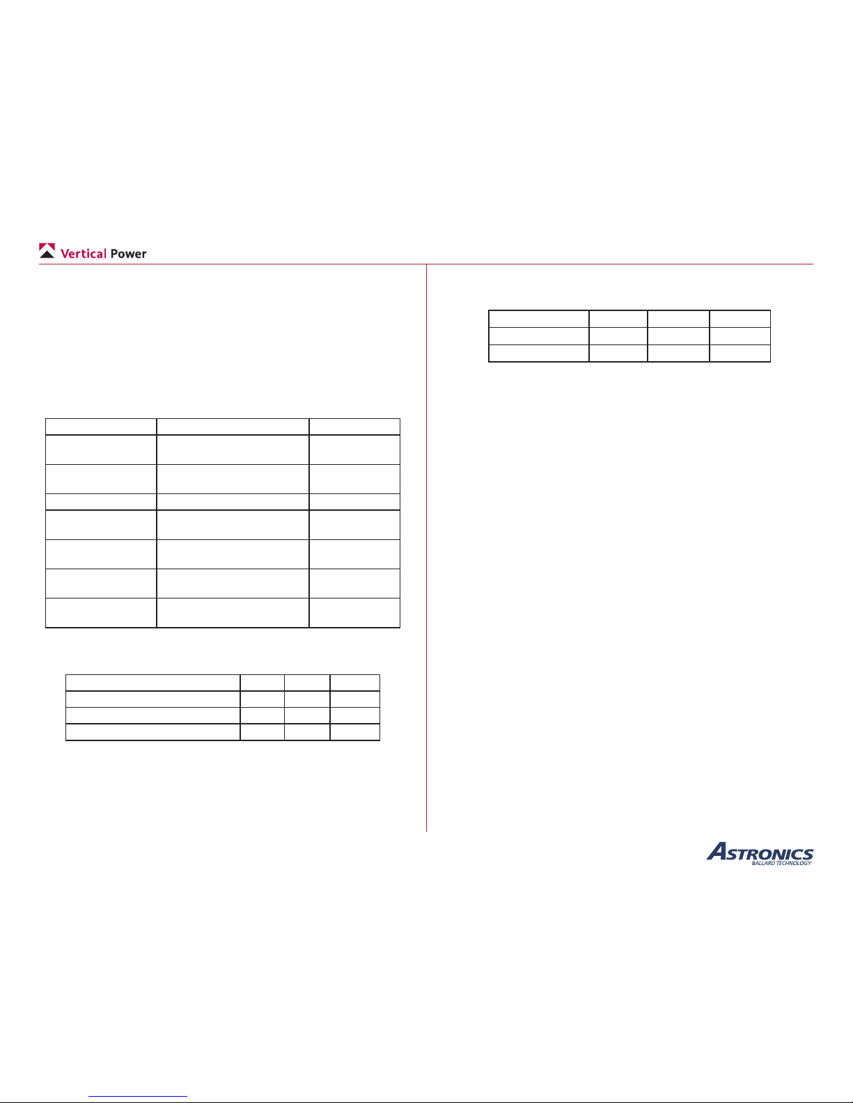
The inputs listed in the table below are inputs that control PPS operation
and are intended to be connected to switches. The switch may be a toggle
or momentary switch depending on the intended use. The switch should
make connection to GND for Open/GND inputs and make connection to
Bus voltage for BUS/Open inputs.
Name Description Type Switch State
MASTER Turn on PPS Open/GND Closed = ON
Open = OFF
MASTER
ALTERNATE
Turn on PPS (Optional –
redundant to MASTER)
Open/GND Closed = ON
Open = OFF
BATT DIST EN Closes the Main Battery
Distribution contactor
Open/GND Closed = ON
Open = OFF
ALT DIST EN Closes the Alternator
Distribution contactor
Open/GND Closed = ON
Open = OFF
MAIN BATT
START EN
Closes the Main Battery
Start contactor
Bus/Open Closed = ON
Open = OFF
PPS Control input pins
The electrical characteristics for Open/GND inputs are listed below.
Specication Min Max
Pin Voltage 0 V 36 V
Open Threshold 500 kΩ –
GND Threshold – 100 Ω
Open/GND Input Electrical Characteristics
The electrical characteristics for BUS/Open inputs are listed below.
Specication Min Max
Pin Voltage 0 V 36 V
High Threshold 7.8 V –
Open Threshold 500 kΩ –
BUS/Open Input Electrical Characteristics
Page 8
Page 4
PPS Installation and Operating Manual
Rev. C.2 (January 19, 2018)
2.4b Status Outputs
The outputs listed in the table below are status outputs from the PPS that
indicate the operational and fault status of the PPS. BUS/GND outputs
are intended to be connected to an LED indicator. Analog outputs are
intended to be connected to equipment (e.g. analog gauges, electronic
gauges, EFIS) that utilizes shunt resistors for current measurement.
A positive output (CURRENT+ above reference) represents “forward
current” (i.e. battery to loads). A negative output (CURRENT+ below
reference) represents “reverse current” (i.e. battery charging).
Name Description Type
BATT DIST FAULT Latched Over-current fault
indication
BUS/GND
ALT DIST FAULT Latched Over-current fault
indication
BUS/GND
STARTER ACTIVE Starter Active indication BUS/GND
BATT CURRENT+ Main Battery current sense
1 mV/A relative to 7.5 V
Analog
BATT CURRENT- Main Battery current sense
7.5 V reference
Analog
ALT CURRENT+ Main Battery current sense
1 mV/A relative to 7.5 V
Analog
ALT CURRENT- Main Battery current sense
7.5 V reference
Analog
PPS output pins
The electrical characteristics of BUS/GND outputs are listed below.
Specication Min Ty p Max
Output Voltage 0 V – BUS
Output Current (at VO=BUS/2) – – 10 mA
Low Output Resistance – 10 kΩ –
BUS/GND Output Electrical Characteristics
The electrical characteristics of analog outputs are listed below. Analog
outputs are protected against shorts to GND.
Specication Min Ty p Max
Output Voltage 2.5 V 7.5 V 12.5 V
Scale
–
1 A/mV
–
Analog Output Electrical Characteristics
Page 9

Page 5
PPS Installation and Operating Manual
Rev. C.2 (January 19, 2018)
3. Electrical System Basics
This manual and the accompanying documentation on the Vertical
Power web site are intended to provide enough detail to understand
overall concepts and safely wire your aircraft. Should you want more
information, additional resources can be found in a variety of books and
texts, a few of which are shown here:
• FAA Advisory Circular AC 43.13, Acceptable Methods,
Techniques, and Practices - Aircraft Inspection and Repair
available from www.faa.gov
• FAA Advisory Circular AC 23.1311, Installation of Electronic
Display in Part 23 Airplanes, available from www.faa.gov
• EAA Hints for Homebuilders
http://www.eaa.org/video/homebuilders.html
• Aircraft Wiring Guide, available from:
http://www.aircraftwiringguide.com/
• Aeroelectric Connection book, available from:
http://www.aeroelectric.com
• Sport Air Electrical Systems Simplied article, available from:
http://www.sportair.com/articles/Electrical Systems Simplied.
html
3.1 Free advice on Designing your Electrical System
Many builders are new to electrical wiring and nd it daunting. Even
experienced electrical engineers may not be familiar with good practices
specic to aircraft wiring. With that in mind, we’ve added lots of detail
throughout this manual. Before we dig into those details, this section
will help you to think about the big picture as you design your electrical
system.
When designing your electrical system, there is a temptation to copy or
do things the same way as your buddy did them when he built his plane.
Avoid that temptation. Every experimental aircraft is different and is used
in different ways. It may end up that your plane, when nished, is similar
in certain ways to your friend’s plane, but that should be because your
requirements are similar and not because you blindly copied him.
We believe the most important free advice we can offer is the following:
CLARIFY YOUR MISSION
In this age of gadgets, it is all too tempting to add just one more
enhancement, then one more again, until we lose sight of how and why
we are building an airplane in the rst place. Think about the most basic
things rst. What will your plane be used for? What type of weather will
you be ying in? What do the worst-case scenarios look like?
The outcome of this decision drives not only how you wire your
electrical system, but also what avionics and other equipment you put in
the aircraft.
If you clarify your mission like this, determining not only what it is but
just as importantly what it isn’t, you will be ready to adopt our next bit of
free advice:
COMMIT YOUR ELECTRICAL SYSTEM TO PAPER
It is surprising to us how many builders, after relying on many pages of
detailed plans for their airframes, use little more than a napkin or a single
sheet of copy paper to draw out their electrical system. Planning and
researching your design and then committing every detail of that design
to hardcopy before you buy equipment and run wires will pay huge
dividends later on.
Whether you’re comfortable with either a pencil or a keyboard, write and
draw everything down, somewhere. Use whatever tools work best for
you—paper, PowerPoint, AutoCAD, or spreadsheets. We cannot design
your electrical system for you, but we can be a valuable sounding-board
for your thoughts. We even have an on-line planning tool at planner.
verticalpower.com that is a big step in the forward direction. After
helping many different customers with many different designs, we’ve
learned that it’s much easier to erase than to rewire. Much cheaper too.
While you commit your design to paper, erasing and redrawing as many
times as it takes to get it right, please keep in mind our last piece of free
advice:
KEEP IT SIMPLE
As a basic rule, the more complex something is the more likely it is to
Page 10

Page 6
PPS Installation and Operating Manual
Rev. C.2 (January 19, 2018)
break. For some reason, while most experimental airplanes are built as
dependable but simple vehicles, their builders are enticed to attach every
electrical bell and whistle they can nd in a catalog. By adding more
relays, busses, terminals, diodes, wires, and (let’s face it) toys, you are
actually adding more things that can fail and more things that make it
harder to troubleshoot.
Before you delve into the details of designing your electrical system,
please consider these three bits of advice. If you do so, the end result will
be an electrical system and avionics package that meets your real needs
when you get your project in the air.
3.2 Basic Concepts
An aircraft electrical system can be divided into three parts:
1. “Backbone” components: aircraft battery, alternator, voltage
regulator, contactors and associated wiring. This is called the
primary power distribution system. Contactors are just high
capacity relays that are energized by low power signals but allow
large amounts of power to pass through.
2. Busses, switches, smaller wiring, and circuit protection (fuses
and/or circuit breakers). This is called the secondary power
distribution system.
3. Users of power and the wiring to and from those users. Users
may be lights, instruments, avionics, pumps, etc. The term device
or load is used in this manual to generically describe all the users.
More on electrical system basics:
• The aircraft battery and alternator provide power to all
electrically-dependent systems. Normally, the battery powers
systems before and during starts and then the alternator takes
over charging the battery and providing power to the electrical
devices. A battery contactor, connects (or disconnects) the
high-current wires between the battery and the main power
distribution bus. The PPS functions as the battery contactor.
• Power typically runs from the battery/alternator to electrical
busses behind the panel where power is split and sent to
individual devices through circuit protection devices (fuses and
circuit breakers) and switches. The VP-X assumes the role of
busses, circuit protection, and a host of single-function modules.
During construction, the VP-X greatly simplies the task of
wiring your aircraft.
• Wire sizes vary and the size of the wire to each device is
determined by the current load (amps) of that device as well as
the distance the current must travel. If a wire is too small for
the load or distance, it will heat up and possibly fail. If the wire
is too big, it will certainly carry the load but at the expense of
added weight.
• To complete the electrical path, devices must have a ground. This
means connecting a ground wire to the metal aircraft structure
(aircraft ground) or running a ground wire from the device to a
central location such as a rewall grounding point.
3.3 Alternator Options
The alternator provides power to devices and also charges the aircraft
battery. The voltage regulator continuously monitors the bus voltage and
adjusts the output of the alternator. The regulator only works when it is
powered from a bus through a wire called the eld wire. Some alternators
are internally regulated (the regulator is built in), and others have
external regulators (a separate box located outside the alternator).
Today’s experimental aircraft are powered by either 14 volt or 28 volts
systems. Often you may hear 12 volt or 24 volt systems. Why the
difference? The reason is because the batteries are rated at either 12 or
24 volts. When the engine is running and the alternator is turned on, the
alternator generates 14 volts or 28 volts, slightly higher than the battery
voltage so it will keep the battery charged.
If you have a primary alternator and a secondary (backup) alternator only
one alternator (eld wire) should be powered on at a time. Therefore, we
refer to one alternator as the primary and the other as the secondary. If
both are on simultaneously, they do not equally “contribute” to powering
the loads. The one whose voltage regulator is set to the highest voltage
will draw all the current (sometimes called current hogging), possibly
overloading the alternator.
Page 11
Page 7
PPS Installation and Operating Manual
Rev. C.2 (January 19, 2018)
When planning your electrical system, assume the alternator provides
80% of its rated output (in amperes), and therefore your total continuous
load (don’t worry about trim or aps or other transient loads) should not
exceed 80% of rated alternator capacity.
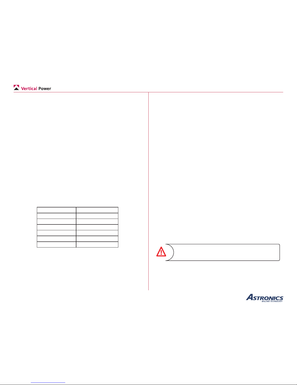
3.4 Wire Sizes and Circuit Protection
A table below shows wires sizes versus loads for a typical homebuilt-size
airplane. The wire size can be larger than necessary but should not be
smaller. Circuit breakers (and fuses) protect the wiring, not the device. If
the breaker is too large, then the wire may overheat and fail. If too small,
then the device may fault (breaker trips) because it draws too much
current.
Most kit aircraft companies and avionics companies provide
recommendations for sizing wires and breakers. You can use these
recommendations. Or, you can borrow or purchase an ammeter (typically
under $50 at Radio Shack, etc.) measure the current draw of each
electrical device and then determine the sizes yourself. When you know
the current draw for each device, use the chart below to size the power
wires. For simplicity, the wiring harnesses available from Vertical Power
use the wire sizes in the table.
Up to (amps) Use wire size (AWG)
5 A 20
10 A 18
15 A 14
80 A 4
300 A (starter) 2
Data signal 22
Recommended wire gauges
3.5 Grounding - IMPORTANT
Many people think that the power, or positive, wire is the most important
wire to provide electricity to a device. The electrical ground is just as
important as electricity must ow the entire path from the power source
to the device and back to the source. The ground wire must be the same
wire gauge or a larger diameter (smaller gauge number) as the wire that
provides power to the device.
A ground loop is when electricity takes two different paths, and each path
has a different resistance. Ground loops are most noticeable in aircraft
audio equipment, and can produce a variety of problems, most notably
unwanted noise.
Several options for grounding your system are provided below. Choose
the one that best ts your needs. Keep in mind that more wiring means
more weight (although likely negligible). Also, note that in all the
examples below the avionics grounds are kept together.
• Option 1: Run a ground wire from each and every electrical
device back to a common grounding point, typically a ground bus
on the rewall.
• Option 2: Run ground wires from all the avionics to an
intermediate grounding point, then run a larger wire from the
local ground bus to the rewall ground. Run wires from all the
other devices to the rewall ground.
• Option 3: Run the ground wires from the avionics to the rewall
ground, and run the other ground wires to a local ground (a metal
part of the airframe located near the device).
The GND Stud connection to the PPS shall be ≤ 2.5 mΩ.
Failure to meet this requirement will damage the PPS and
lead to an unsafe condition.
Page 12
Page 8
PPS Installation and Operating Manual
Rev. C.2 (January 19, 2018)
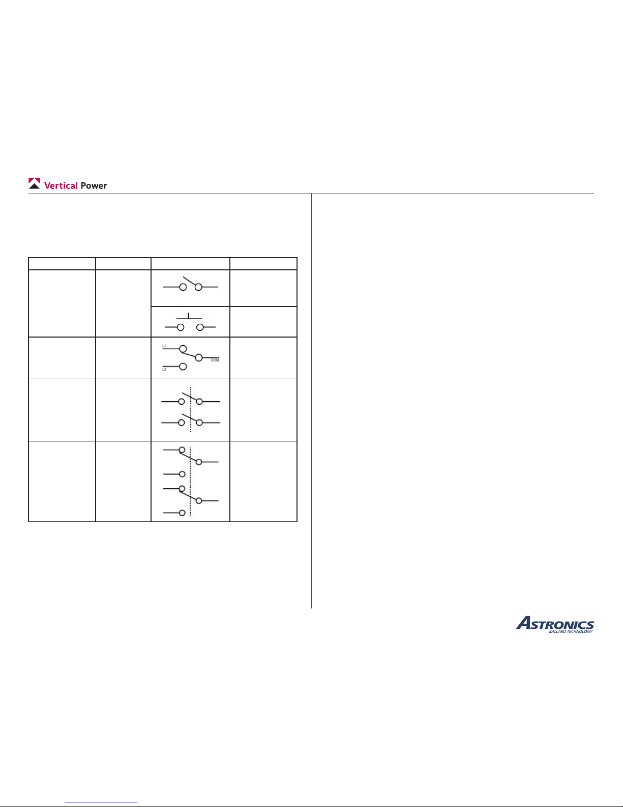
3.6 Switch Nomenclature
The chart below shows the most common switch types. A parenthesis
() around a switch position indicates it is a momentary, spring-loaded
position.
Switch Type Designation Symbol Mechanism
Single Pole,
Single Throw
SPST OFF-ON
OFF-(ON)
Single Pole,
Double Throw
SPDT ON-NONE-ON
ON-OFF-ON
(ON)-OFF-(ON)
ON-OFF-(ON)
Double Pole,
Single Throw
DPST OFF-ON
OFF-(ON)
Double Pole,
Double Throw
DPDT ON-NONE-ON
ON-OFF-ON
(ON)-OFF-(ON)
ON-OFF-(ON)
PPS Control input pins
3.7 Current Sensing (Shunt)
When planning your aircraft electrical wiring you must consider whether
to wire an ammeter (usually a shunt or hall effect sensor provided with
the engine monitor) on the wire connecting the alternator(s) to the
main bus. The ammeters indicate the amount of current the alternator is
providing.
A shunt is not required to tell if the alternator is working. It is very easy
to tell if the alternator is working correctly by simply looking at voltage.
If you see 14 (or so) volts with the engine running then it is working. If
you see 12 (or so) volts it is not working or not turned on or the devices
are drawing more current than the alternator can provide (note, engine
must be running). If you set your low voltage alarm on the EFIS at 13
volts, then you will get a low voltage alarm if the alternator fails.
The PPS provides the alternator current (shunt) output, which shows
the amount of current the alternator is providing to power the devices
and charge the battery. The VP-X total current reading shows the total
amount of current the devices attached to the VP-X are using. The delta
between the two is the battery charging current, which goes to zero after
re-charging any loss from starting the engine or charging a run-down
battery.
If the battery charging current is important to you, the PPS also provides
a battery current (shunt) output as well. If not, then simplify your wiring
and don’t utilize this PPS output. Your call. And of course each builder’s
needs are different so there is no absolutely right answer.
The EFIS displays a VP-X page which shows individual device current
as well as total current through the VP-X. The EFIS also has an ‘Amps’
gauge that is used to show the readings from the shunt. In some cases the
EFIS ‘Amps’ gauge can be used to display total system current from the
VP-X. Please check with your EFIS manufacturer for details.
If you don’t use the PPS current outputs then the shunt wires on the
engine monitor/ EFIS are not used.
Page 13
Page 9
PPS Installation and Operating Manual
Rev. C.2 (January 19, 2018)
4. Installation and Test
Installation of the PPS is accomplished in four main steps. Following
these steps will increase the likelihood of a trouble-free electrical system.
Taking time to plan your electrical system will pay big dividends later on.
• Planning
• Installation
• Ground Test
• Flight Test
4.1 Planning
It is a good idea to spend time on the planning stage whether you are
installing a simple or a complex aircraft electrical system.
A wiring harness for the PPS circular connector is available to simplify
the installation of electrical system.
The wiring diagrams in this section illustrate typical basic installations
with traditional wiring and with the Vertical Power VP-X electronic
circuit breaker system. Wiring diagrams also show alternate or advanced
installation options that may or may not be needed for your installation.
Utilize this manual and the wiring diagrams to create a plan for your
aircraft wiring prior to performing the installation.
4.1a Tools and Supplies
This is a generic list of items to assist with planning. Some items may
vary depending on the requirements of your specic installation.
• Crimper - insulated terminals 20 AWG
• Crimper - TE Connectivity Hand Crimper 601966-1 (or
equivalent) and TE Connectivity Positioner 601966-5 (or
equivalent)
• Crimper – terminals for 2 to 8 AWG wire
• Stripper – for wire 20 AWG
• Heavy gauge wire for “main” power runs
• Battery contactor (optional for remote mounted battery)
• Alternator(s) and voltage regulator(s)
• Switches
• Indicators
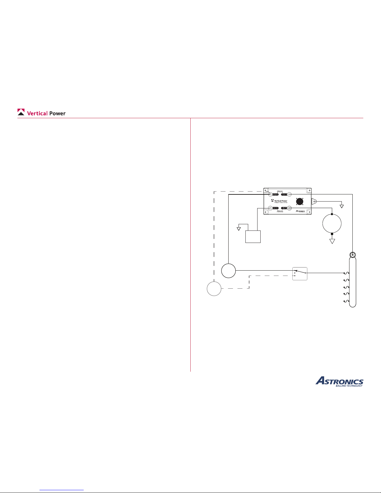
4.1b Wiring Diagrams
The following wiring diagrams provide an overview for wiring the PPS
in traditional systems, systems with the Vertical Power VP-X, and in
systems with an AFT mounted battery.
+
-
Battery
STARTER
F
B
PRI
ALT
F
B
Backup
ALT
Optional
MAIN BUS
on-off-on
Notes:
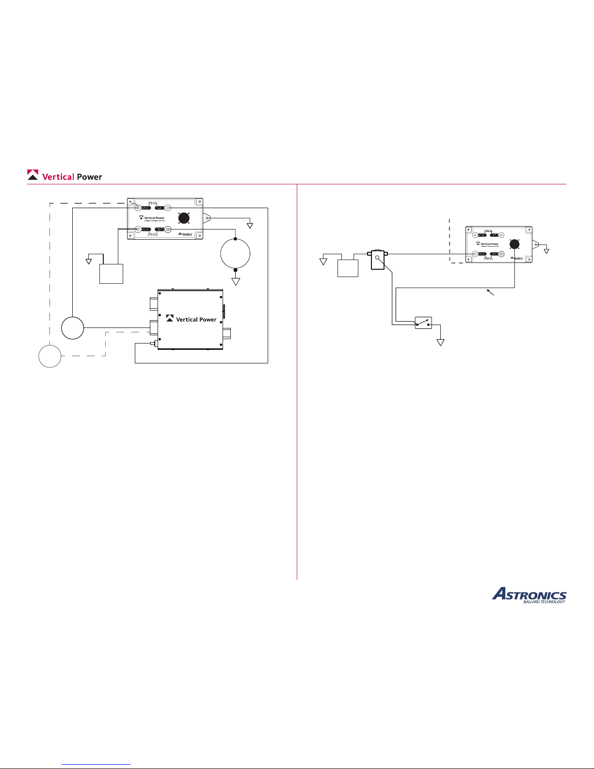
1. The GND Stud connection to the PPS shall be ≤ 2.5 mΩ. Failure to
meet this requirement will damage the PPS and lead to an unsafe condition.
2. External voltage regulator and overvoltage protection module not shown
(may or may not be needed, depending on alternator)
Alt Field
Switch
GND Stud (see note 1)
PPS wiring overview with traditional wiring
Note: Alternator eld switch shown if for example purposes only. Other
variants that achieve the same function electrically can be used, such
as two individual switches, a split master/alternator switch, and other
common variants.
Page 14
Page 10
PPS Installation and Operating Manual
Rev. C.2 (January 19, 2018)
+
-
Battery
STARTER
F
B
PRI
ALT
F
B
Backup
ALT
Optional
VP-X
J10
J12
J1, J2
J8
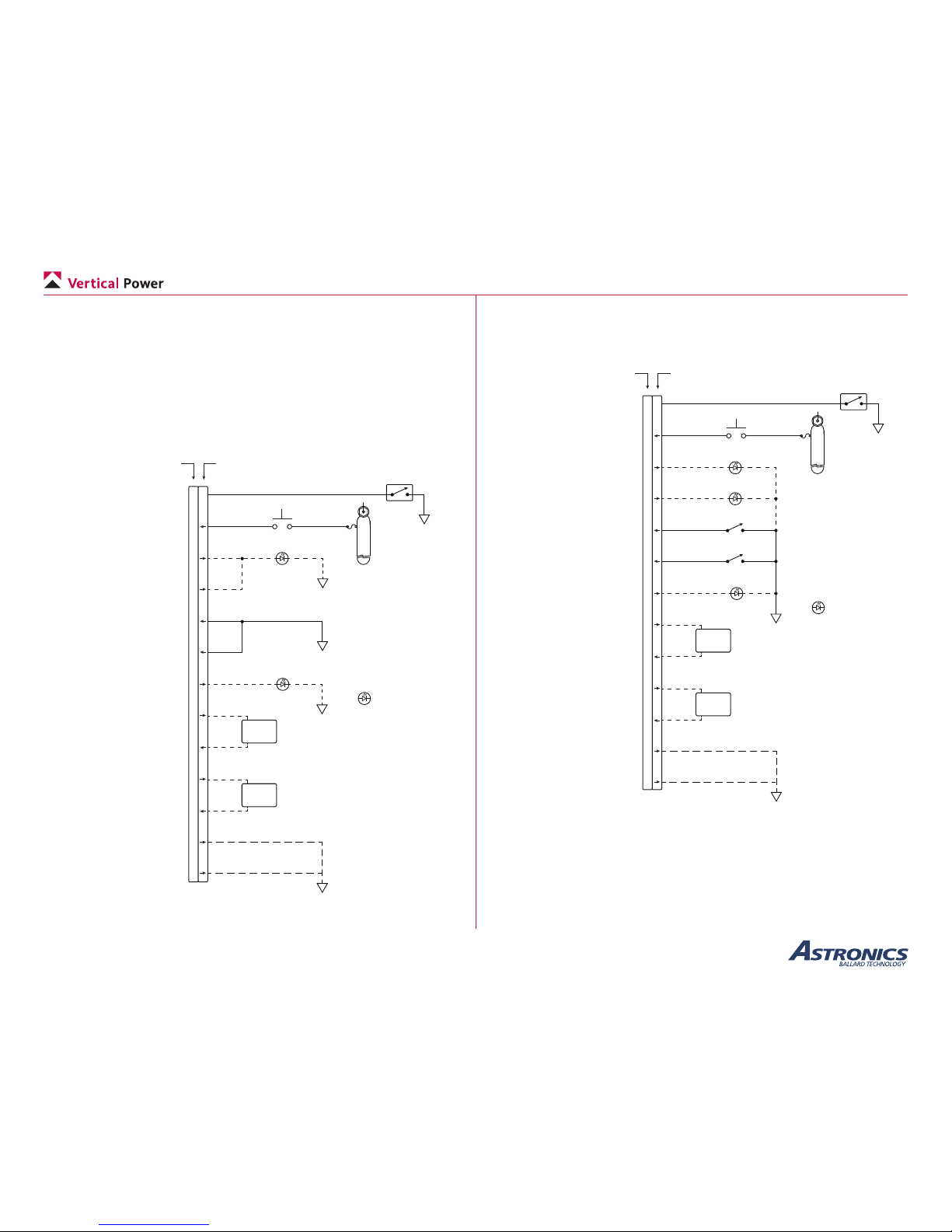
GND Stud (see note 1)
Notes:
1. The GND Stud connection to the PPS shall be ≤ 2.5 mΩ. Failure to
meet this requirement will damage the PPS and lead to an unsafe condition.
2. External voltage regulator not shown
(may or may not be needed, depending on alternator)
PPS Wiring Overview with the Vertical Power VP-X
Aircraft with a remote mounted battery may require the addition of a
battery contactor near the battery as shown in the following diagram:
+
-
Battery
Rear of Aircraft
Firewall
Front of Aircraft
To 28-pin connector
Master Switch
GND
SPST
OFF-ON
Battery
Contactor
(near
battery)
GND Stud
(see note 1)
Note:
1. The GND Stud connection to the PPS
shall be ≤ 2.5 mΩ. Failure to meet this
requirement will damage the PPS and
lead to an unsafe condition.
PPS with remote mounted battery
Page 15
Page 11
PPS Installation and Operating Manual
Rev. C.2 (January 19, 2018)
Depending on the level of control required two installation methods are
available - basic and comprehensive. Basic installs minimize the number
of switches and indicators needed and match well with existing panel
wiring for retrot applications. The comprehensive method requires more
wiring, but allows individual reset control of faults.
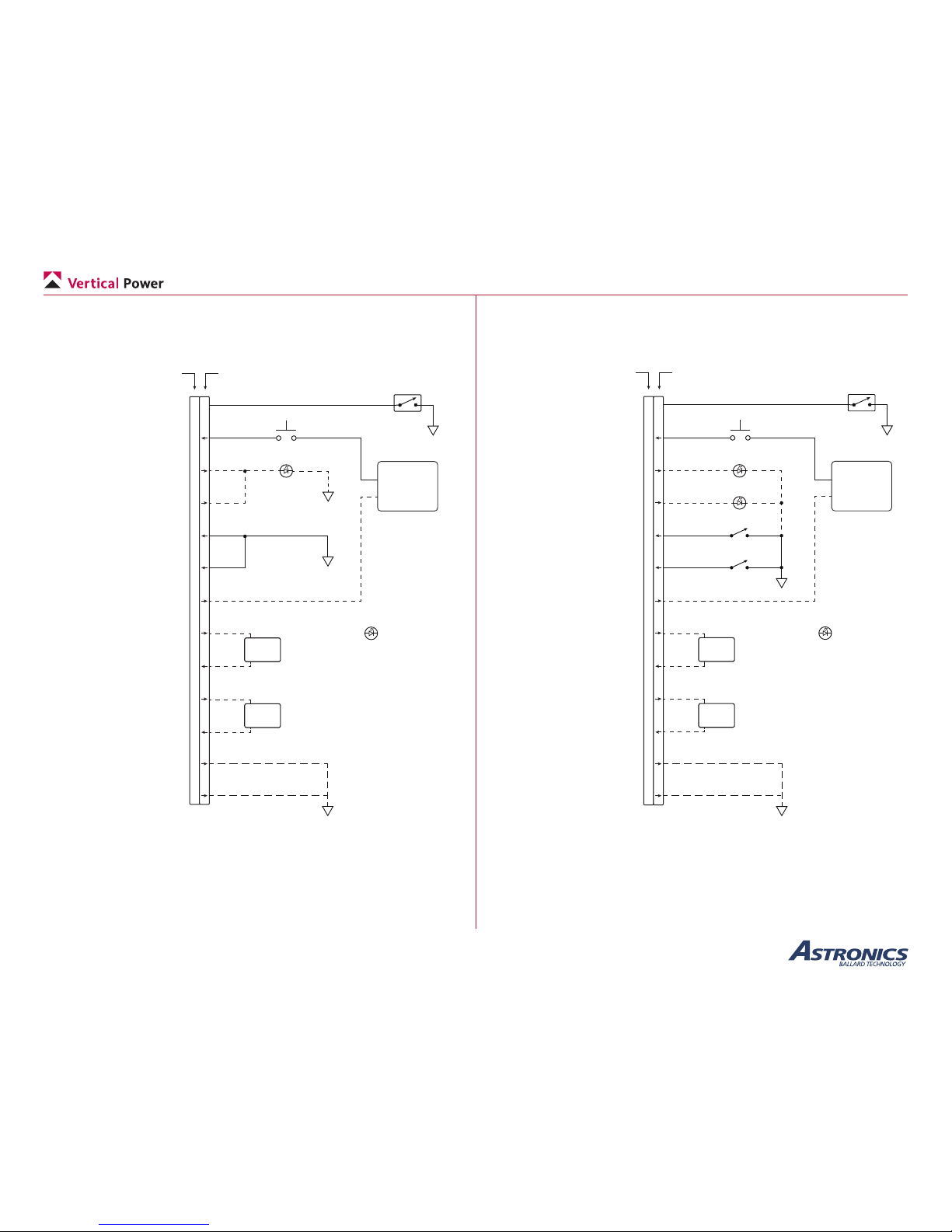
Basic Installation with Traditional wiring.
The image below details basic PPS connector wiring for an aircraft with
traditional wiring:
28-pin female circular connector
(on PPS)
28-pin male circular connector
(on wiring harness, optional accessory)
= LED on instrument
panel, 10 mA max
7
3
14
13
1
8
10
9
20
19
18
26
27
Master Switch
GND
GND
SPST
OFF-ON
Starter Switch
OFF-(ON)
Fault Lamp
MAIN BUS
Starter
1A
Panel
Ampmeter
or EFIS
GND
Starter Engaged Lamp
Master switch input
Ground to close ‘master solenoid
Main battery starter switch input
+12/24 volts to engage starter
Main battery fault lamp output
+12/24 volts when PPS faulted
Alternator fault lamp output
+12/24 volts when PPS faulted
Main battery distribution enable input
Ground to enable
Alternator distribution enable input
Ground to enable
Starter indicator output
+12/24 volts when starter engaged
Battery Current (+)
Battery Current (–)
Alternator Current (+)
Alternator Current (–)
Ground
Ground
GND
GND
All wires 22 AWG.
Lamp outputs are
current limited
and do not require
an external fuse.
Optional
(Recommended)
Optional
Panel
Ampmeter
or EFIS
Optional
(Recommended)
Optional
Both of these grounds must
be connected.
(Maximum wire length: 24 in.)
Twist together sense lines
on pins 9 and 20 to reduce
common mode noise
Twist together sense lines
on pins 19 and 18 to reduce
common mode noise
PPS basic installation with traditional wiring
Comprehensive Installation with Traditional wiring.
The image below details comprehensive PPS connector wiring for an
aircraft with traditional wiring:
28-pin female circular connector
(on PPS)
28-pin male circular connector
(on wiring harness, optional accessory)
= LED on instrument
panel, 10 mA max
7
3
14
13
1
8
10
9
20
19
18
26
27
Master Switch
GND
SPST
OFF-ON
Starter Switch
OFF-(ON)
MAIN BUS
Starter
1A
Panel
Ampmeter
or EFIS
GND
Starter Engaged Lamp
Master switch input
Ground to close ‘master solenoid
Main battery starter switch input
+12/24 volts to engage starter
Main battery fault lamp output
+12/24 volts when PPS faulted
Alternator fault lamp output
+12/24 volts when PPS faulted
Main battery distribution enable input
Ground to enable
Alternator distribution enable input
Ground to enable
Starter indicator output
+12/24 volts when starter engaged
Battery Current (+)
Battery Current (–)
Alternator Current (+)
Alternator Current (–)
Ground
Ground
All wires 22 AWG.
Lamp outputs are
current limited
and do not require
an external fuse.
Optional
Panel
Ampmeter
or EFIS
Optional
(Recommended)
Optional
(Recommended)
Optional
(Recommended)
Optional
Main Battery Fault Reset
SPST OFF-ON
Main Battery Fault Reset
SPST OFF-ON
Main Battery Fault Lamp
Alternator Fault Lamp
GND
Both of these grounds must
be connected.
(Maximum wire length: 24 in.)
Twist together sense lines
on pins 9 and 20 to reduce
common mode noise
Twist together sense lines
on pins 19 and 18 to reduce
common mode noise
PPS comprehensive installation with traditional wiring
Page 16
Page 12
PPS Installation and Operating Manual
Rev. C.2 (January 19, 2018)
Basic Installation with the Vertical Power VP-X.
The image below details basic PPS connector wiring for an aircraft wired
with the Vertical Power VP-X:
28-pin female circular connector
(on PPS)
28-pin male circular connector
(on wiring harness, optional accessory)
= LED on instrument
panel, 10 mA max
7
3
14
13
1
8
10
9
20
19
18
26
27
Master Switch
GND
GND
SPST
OFF-ON
Starter Switch
OFF-(ON)
Fault Lamp
Panel
Ampmeter
or EFIS
Master switch input
Ground to close ‘master solenoid
Main battery starter switch input
+12/24 volts to engage starter
Main battery fault lamp output
+12/24 volts when PPS faulted
Alternator fault lamp output
+12/24 volts when PPS faulted
Main battery distribution enable input
Ground to enable
Alternator distribution enable input
Ground to enable
Starter indicator output
+12/24 volts when starter engaged
Battery Current (+)
Battery Current (–)
Alternator Current (+)
Alternator Current (–)
Ground
Ground
GND
All wires 22 AWG.
Lamp outputs are
current limited
and do not require
an external fuse.
Optional
(Recommended)
Optional
Panel
Ampmeter
or EFIS
Optional
(Recommended)
Optional
GND
Both of these grounds must
be connected.
(Maximum wire length: 24 in.)
VP-X
J10-1 (set to 1 amp)
J2-11 Starter input
Twist together sense lines
on pins 9 and 20 to reduce
common mode noise
Twist together sense lines
on pins 19 and 18 to reduce
common mode noise
PPS basic installation with the Vertical Power VP-X
Comprehensive Installation with the Vertical Power VP-X.
The image below details comprehensive PPS connector wiring for an
aircraft wired with the Vertical Power VP-X:
28-pin female circular connector
(on PPS)
28-pin male circular connector
(on wiring harness, optional accessory)
= LED on instrument
panel, 10 mA max
7
3
14
13
1
8
10
9
20
19
18
26
27
Master Switch
GND
SPST
OFF-ON
Starter Switch
OFF-(ON)
Panel
Ampmeter
or EFIS
Master switch input
Ground to close ‘master solenoid
Main battery starter switch input
+12/24 volts to engage starter
Main battery fault lamp output
+12/24 volts when PPS faulted
Alternator fault lamp output
+12/24 volts when PPS faulted
Main battery distribution enable input
Ground to enable
Alternator distribution enable input
Ground to enable
Starter indicator output
+12/24 volts when starter engaged
Battery Current (+)
Battery Current (–)
Alternator Current (+)
Alternator Current (–)
Ground
Ground
All wires 22 AWG.
Lamp outputs are
current limited
and do not require
an external fuse.
Optional
Panel
Ampmeter
or EFIS
Optional
(Recommended)
Optional
Starter Switch
OFF-(ON)
GND
Optional
(Recommended)
Optional
(Recommended)
Main Battery Fault Reset
SPST OFF-ON
Main Battery Fault Reset
SPST OFF-ON
Main Battery Fault Lamp
Alternator Fault Lamp
GND
Both of these grounds must
be connected.
(Maximum wire length: 24 in.)
VP-X
J10-1 (set to 1 amp)
J2-11 Starter input
Twist together sense lines
on pins 9 and 20 to reduce
common mode noise
Twist together sense lines
on pins 19 and 18 to reduce
common mode noise
PPS comprehensive installation with the Vertical Power VP-X
Page 17
Page 13
PPS Installation and Operating Manual
Rev. C.2 (January 19, 2018)
4.2 Installation
Prior to installation, be sure to review and understand your wiring plan.
During installation, the battery should NOT be connected
until the wiring is installed and tested.
Tip: Disconnect the battery ground cable rst, then the positive cable.
When re-connecting, connect the positive cable rst then the ground
cable. Doing so ensures you won’t spark the positive connection to the
airframe.
4.2a Mount the PPS
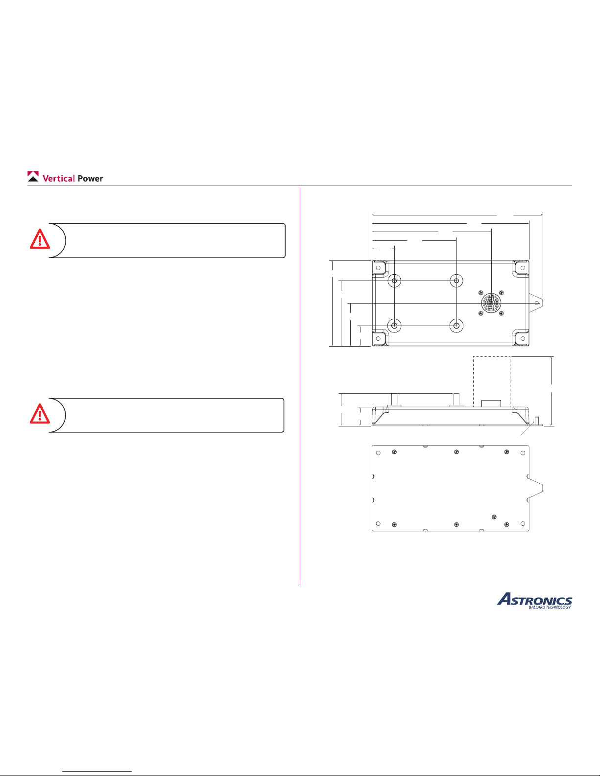
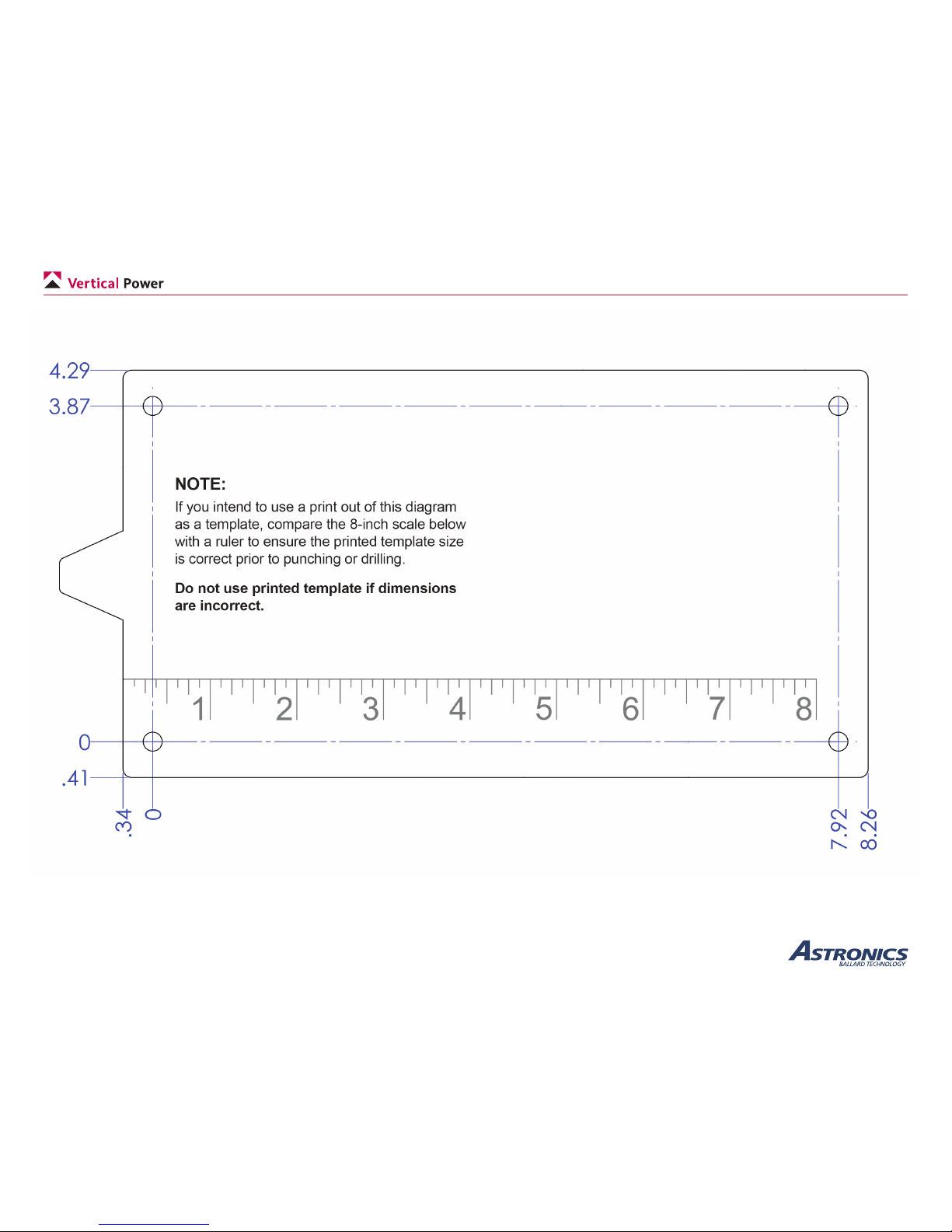
The PPS should be mounted to the rewall, or other desired location,
using 4 #10 bolts (not included). A drill/punch template is provided
on the next page. You can print this as a guide for easy hole location
(Important: prior to using, you must verify the dimensions of the printed
template according to the instructions on the template).
When mounting the PPS to the firewall, a firewall
sealant should be used around any penetrations as a
barrier against the ingress of fire or fumes.
4.70
6.53
2.35
1.12
3.58
1.23
4.63
8.61
All Dimensions
are in inches
1.89
1.04
3.75
Clear
space for
connector
9.31
10-32 threaded GND stud
PPS Mechanical Diagram
Page 18
Page 14
PPS Installation and Operating Manual
Rev. C.2 (January 19, 2018)
PPS Mounting Template
Page 19
Page 15
PPS Installation and Operating Manual
Rev. C.2 (January 19, 2018)
4.2b Terminal Wiring
Per your installation plan, route wires and make connections to the
terminals for the starter, main bus output, alternator b-lead(s) and
battery. Use the included at washer, lock washer, and nut to secure each
connection and torque according to the table below.
Terminal Size Nominal Torque Maximum Torque
Main Battery 5/16”-18 83.5 in-lb (6.9 ft-lb) 90 in-lb (7.5 ft-lb)
Starter Out
Alt 1 & 2 B-Lead In 1/4”-20 40.5 in-lb (3.4 ft-lb) 45 in-lb (3.7 ft-lb)
Main Bus Out
GND Stud 10-32 20 in-lb (1.6 ft-lb) 25 in-lb (2.1 ft-lb)
PPS Terminal Torque Table
Electrical anti-corrosion/corrosion inhibitor lube should be used on all
power distribution cable connections (main bus, alternator, battery, starter
and grounds).
4.2c Control/Status Wiring
Per your installation plan, route wires for the switches and indicators.
Crimp and install these wires into the circular connector.
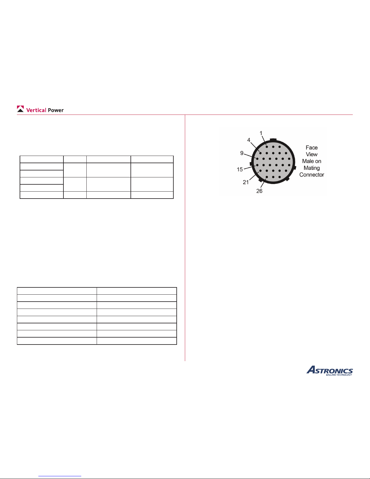
The PPS uses TE Connectivity circular plastic connectors for J1. The
mating TE Connectivity connectors are recommended for compatibility.
Included in the table below are the recommended mating connectors and
individual crimp pins.
J1 Connector
Positions 28
Contact size 20 gauge
Mating connector 206039-1
Backshell, straight 206070-8
Backshell, right-angle 1546349-2
Crimp Contacts, stamped 1-66506-0
Crimp Contacts, machined 205089-1
PPS Mating Connector Part Numbers
PPS Mating Connector View
If using the optional wiring harness, run each pre-crimped wire of the
harness from the PPS connector to the switch/indicator location. Trim the
excess length and terminate the wire to the switch/indicator. Insert the
pre-crimped end of the wire into the circular connector.
Page 20

Page 16
PPS Installation and Operating Manual
Rev. C.2 (January 19, 2018)
J1 Connector
Name Description Type Pin #
BATT DIST EN Closes the Main Battery Distribution
contactor
Open/GND
Input
1
RSVD Reserved (do not connect) 2
MAIN BATT START ENCloses the Main Battery Start contactor BUS/Open
Input
3
RSVD Reserved (do not connect) 4
RSVD Reserved (do not connect) 5
MASTER
ALTERNATE
Turn on PPS (Alternate - redundant to
MASTER pin 7)
Open/GND
Input
6
MASTER Turn on PPS (Redundant with pin 6) Open/GND
Input
7
ALT DIST EN Closes the Alternator Distribution contactor Open/GND
Input
8
BATT CURRENT+ Main Battery current sense 1 mV/A relative
to 7.5 V
Analog 9
STARTER ACTIVE Starter Active indication BUS/GND
Output
10
RSVD Reserved (do not connect) 11
RSVD Reserved (do not connect) 12
ALT DIST FAULT Latched Over-current fault indication BUS/GND
Output
13
BATT DIST FAULT Latched Over-current fault indication BUS/GND
Output
14
RSVD Reserved (do not connect) 15
RSVD Reserved (do not connect) 16
RSVD Reserved (do not connect) 17
ALT CURRENT- Main Battery current sense 7.5 V reference Analog 18
ALT CURRENT+ Main Battery current sense 1 mV/A relative
to 7.5 V
Analog 19
BATT CURRENT- Main Battery current sense 7.5 V reference Analog 20
RSVD Reserved (do not connect) 21
RSVD Reserved (do not connect) 22
RSVD Reserved (do not connect) 23
RSVD Reserved (do not connect) 24
RSVD Reserved (do not connect) 25
GND Ground (must connect both pins 26 and 27
to GND - maximum wire length: 24 inches)
26
27
RSVD Reserved (do not connect) 28
4.3 Ground Test
The ground test steps are performed in two parts: the rst part without
the engine running and the second part with the engine running.
4.3a Ground Test without engine running
Perform the following steps without the engine running. Prevent engine
from starting during cranking by shutting off fuel and/or having mag
switches in the off position. The battery will drain during testing, so have
either a charger or ground power available.
• Turn on the master switch
• If installed, turn on the main battery enable switch
• Verify main bus power
• Use a multi-meter or verify load device is operational
• If installed, verify the main bus current output.
• Verify starter cranking
• Turn the starter switch to the on position for a few seconds
• Verify the starter indicator if used.
• When installing with a VP-X, perform VP-X ground testing
without engine running at this time.
4.3b Start Mode Duty Cycle
The PPS was designed to be more tolerant to overheating than most
starters, but measures should still be taken to limit heat build up in
the PPS. First and most important is to always follow your starter
manufacturer’s published duty cycle guidelines. In most cases, this will
be adequate to prevent heat damage to the PPS.
For reference, here are the start mode duty cycle guidelines for the PPS:
• Each starting attempt must not exceed 20-seconds.
• After each starting attempt, there must be a 60-second rest time.
• After three (3) starting attempts, a 10-minute cool down period is
required.
Page 21
Page 17
PPS Installation and Operating Manual
Rev. C.2 (January 19, 2018)
4.3c Ground Test with engine running
This section veries the proper operation of the PPS with the engine
running. If this is coincident with rst engine start, be sure to integrate
the kit manufacturer’s rst engine start safety procedures with the test
plan below. You may consider rst verifying proper operation of the
engine and once that is complete, begin the electrical system test.
Prolonged low-power operation of a new engine may adversely affect the
engine. Be sure you understand the engine break-in requirements, and
balance those against the time needed to test the electrical system.
The following tests should be used as a guideline. Follow the engine
manufacturer’s starting and safety procedures.
• Ensure that the battery is fully charged. If the voltage drops
rapidly during engine start, then the battery is bad or not fully
charged.
• Start the engine.
• Note the bus voltage. Then turn on the primary alternator. If
installed turn on the alternator enable to the PPS.
• The voltage should increase to 14.2 volts +/- 0.3 volts (check
with your alternator manufacturer for specics)
• If installed, verify the alternator current output.
• If installed, verify the main bus current output. Current should
show charging or zero current ow once alternator is operating.
• Verify the each alternator can be turned off and on.
• If installed, turn on the alternator enable to the PPS on and off.
Verify correct operation.
• If installed, turn the main battery enable to the PPS on and off.
Verify correct operation.
• Turn off all switches.
4.4 Flight Test
Prior to ight, make sure you understand how to operate the PPS and
clear faults. This section provides a series of recommended steps which
should be incorporated into the overall ight test plan as you deem
appropriate. Review the ground test steps, as complete and thorough
ground testing will mitigate the risk of trouble while airborne.
Do not fly the aircraft until you are comfortable everything
operates correctly on the ground and you are knowledgeable about the systems and their proper operation.
It is the pilot’s responsibility to develop a test plan that ensures a safe and
productive rst ight. Typically, the rst ight is focused on verifying
basic ight characteristics and proper engine operation. With that in
mind, we recommend deferring complete electrical system tests until
after you are comfortable that the engine and airframe are performing as
expected, and you are comfortable ying the aircraft.
If you are installing the system as a retrot, it is still important to
complete as much of the testing on the ground as possible.
Once airborne, keep an eye out for trafc and obstacles during the test
procedure. Carry a handheld radio as a backup in case of electrical
system failure. If you encounter any difculties in ight due to improper
setup or unknown electrical system behavior, land as soon as practical or
simply turn off the master switch.
Verify backup power is ON for ignition and required
devices prior to turning off the master switch.
If you have completed a thorough check out on the ground, the chances
of problems while airborne are greatly reduced.
Verify each of the following in ight:
• Verify the each alternator can be turned off and on.
• If installed, turn on the alternator enable to the PPS on and off.
Verify correct operation.
• If installed, turn the main battery enable to the PPS on and off.
Verify correct operation.
Page 22
Page 18
PPS Installation and Operating Manual
Rev. C.2 (January 19, 2018)
5. Maintenance
5.1 Do’s and Don’ts
The PPS unit is maintenance free, but the following routine power
system do’s and don’ts are recommended:
• Do routinely check all the power distribution cable connection
fastener torques on the interconnects to the PPS, alternator,
battery, starter and grounds
• Do not expose the PPS directly to spray wash/uids.
6. Troubleshooting
This chapter provides information to assist in troubleshooting the PPS
installation. If the problem(s) cannot be resolved using the information in
this chapter, please contact Customer Service.
6.1 Common Problems
Several common installation problems are listed below along with
potential resolutions.
Problem Resolutions
Main Bus Voltage
not present
Use multi-meter to verify bus voltage is present at
Main Battery input terminal.
Use multi-meter to verify that Master switch input
(primary or alternate) voltage is ground (must be
below minimum input voltage).
Use multi-meter to verify that Main contactor switch
input voltage is ground (must be below minimum
input voltage).
Verify that no fault is present. Use multi-meter to
verify that Main contactor fault output is ground.
Main Bus Voltage is
less than 13 V or 26
V when Alternator is
enabled
Use multi-meter to verify bus voltage is present at
Alternator input terminal and is above 13 V or 26 V.
Use multi-meter to verify that Alternator contactor
switch input voltage is ground (must be below
minimum input voltage).
Verify that no fault is present. Use multi-meter to
verify that Alternator contactor fault output is ground.
Engine not turning
over or starting
Disconnect starter from PPS and verify that starter
circuit is operational. With the master on, enable
the starter and verify either voltage is present at
the starter output terminal or that the starter active
indicator lights.
Common Problems/Resolutions
Page 23

Page 19
PPS Installation and Operating Manual
Rev. C.2 (January 19, 2018)
7. Specications
7.1 General
• Transient protection on all connections
7.2 Circuit Ratings
• Main Bus Output: 80 A maximum continuous
• Starter Output
• 300 A maximum continuous
• 1200 A maximum intermittent
• Alternator Input
• 80 A maximum continuous
• Analog Current Monitor Outputs
• Common-mode reference of 7.5 VDC
• Scale: 1 mV/Amp
• Short circuit protected
7.3 Environmental / Physical
• Component Temperature Range: −40°C to +85°C
• Storage Temperature Range: −55°C to +100°C
• Size: 4.7 x 8.65 inches
• Weight: 1.6 lb (0.72 kg)
• Operating Voltage: 8 – 36 VDC
• Low quiescent power: less than 1 mA at 14 VDC and 28 VDC
• Maximum power
• 320 mA at 14 VDC
• 140 mA at 28 VDC
 Loading...