

Page 1

Artisan Technology Group is your source for quality
new and certied-used/pre-owned equipment
• FAST SHIPPING AND
DELIVERY
• TENS OF THOUSANDS OF
IN-STOCK ITEMS
• EQUIPMENT DEMOS
• HUNDREDS OF
MANUFACTURERS
SUPPORTED
• LEASING/MONTHLY
RENTALS
• ITAR CERTIFIED
SECURE ASSET SOLUTIONS
SERVICE CENTER REPAIRS
Experienced engineers and technicians on staff
at our full-service, in-house repair center
Instra
Remotely inspect equipment before purchasing with
our interactive website at www.instraview.com
Contact us: (888) 88-SOURCE | [email protected] | www.artisantg.com
SM
REMOTE INSPECTION
View
WE BUY USED EQUIPMENT
Sell your excess, underutilized, and idle used equipment
We also offer credit for buy-backs and trade-ins
www.artisantg.com/WeBuyEquipment
LOOKING FOR MORE INFORMATION?
Visit us on the web at www.artisantg.com for more
information on price quotations, drivers, technical
specications, manuals, and documentation
Page 2

Trig-Tek™
850A/B
Contact Chatter Detector
User Manual
Publication No. 98 0 972 Rev. B
Astronics Test Systems Inc.
4 Goodyear, Irvine, CA 92618
Tel: (800) 722-2528, (949) 859-8999; Fax: (949) 859-7139
[email protected] http://www.astronicstestsystems.com
Copyright 2011 by Astronics Test Systems Inc. Printed in the United States of Amer ica. All rights reserved.
This book or parts thereof may not be reproduced in any form without written permission of the publisher.
Artisan Technology Group - Quality Instrumentation ... Guaranteed | (888) 88-SOURCE | www.artisantg.com
Page 3

THANK YOU FOR PURCHASING THIS
ASTRONICS TEST SYSTEMS PRODUCT
For this product, or any other Astr onics Test Systems product that incorporat es software drivers,
you may access our web site to verify and/or download the latest driver versions. The web
address for driver downloads is:
http://www.astronicstestsystems.com/support/downloads
If you have any questions about software driver downloads or our privacy policy, please contact
us at:
WARRANTY STATEMENT
All Astronics Test Systems products are desig ned to exacting standards and manufactured in full
compliance to our AS9100 Quality Management System processes.
This warranty does not apply to defects resulting f rom any modification(s) of any product or part
without Astronics Test Systems express written consent, or misuse of any product or part. The
warranty also does not apply to fuses, software, non-rechargeable batteries, damage from
battery leakage, or problems arising f rom normal wear, such as mechanical r elay lif e, or failure to
follow instructions.
This warranty is in lieu of all other warranties, expressed or implied, including any implied
warranty of merchantability or fitness for a particular use. The remedies provided herein are
buyer’s sole and exclusive remedies.
For the specific terms of your standard warranty, contact Cust omer Support. Please have the
following information available to facilitate service.
1. Product serial number
2. Product model number
3. Your company and contact information
You may contact Customer Support by:
Fax: +1 949 859 7139 (USA)
Artisan Technology Group - Quality Instrumentation ... Guaranteed | (888) 88-SOURCE | www.artisantg.com
Page 4

RETURN OF PRODUCT
Authorization is required from Astronics Test Systems before you send us your product or sub-assem bly for
service or calibration. Call or contac t Custom er Support at 1-800-722-3262 or 1-949-859-8999 or via fax at
1-949-859-7139. We can also be reached at: [email protected]
If the original packing material is unavailable, ship the product or sub-assembly in an ESD shielding bag and
use appropriate packing materials to surround and protect the product.
.
PROPRIETARY NOTICE
This document and the technic al data herein disc los ed, are pr oprietar y to Astronics Test Systems, and shall
not, without express written permission of Astronics Test Systems, be used in whole or in part to solicit
quotations from a competitive source or used for manufacture by anyone other than Astronics Test
Systems. The information herein has been developed at private expense, and may only be used for
operation and maintenance referenc e purposes or for purposes of engineering evaluation and incorporation
into technical specifications and other documents which specify procurement of products from Astronics
Test Systems.
TRADEMARKS AND SERVICE MARKS
All trademarks and service marks used in this document are the property of their respective owners.
• Racal Instruments, Talon Instruments, Trig-Tek, ActivATE, Adapt-A-Switch, N-GEN, and PAWS are
trademarks of Astronics Test Systems in the United States.
DISCLAIMER
Buyer acknowledges and agrees that it is responsible for the operation of the goods purchased and should
ensure that they are used properly and in accordance with this document and any other instructions
provided by Seller. Astronics Test Systems products are not specifically designed, manufactured or
intended to be used as parts, assemblies or components in planning, construction, maintenance or
operation of a nuclear facility, or in life support or safety critical applications in which the failure of the
Astronics Test Systems product could create a situation where personal injury or death could occur. Should
Buyer purchase Astronics Test Systems product for such unintended application, Buyer shall indemnify and
hold Astronics Test Systems, its officers, employees, subsidiaries, affiliates and distributors harmless
against all claims arising out of a claim for personal injury or death associated with such unintended use.
Artisan Technology Group - Quality Instrumentation ... Guaranteed | (888) 88-SOURCE | www.artisantg.com
Page 5
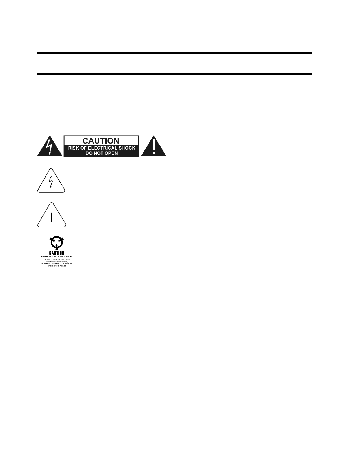
FOR YOUR SAFETY
Before undertaking any troubleshooting, maintenance or exploratory procedure, read carefully the
WARNINGS and CAUTION notices.
This equipment contains voltage hazardous to
human life and safety, and is capable of
If this instrument is to be powered from the AC line (mains) through an autotransformer,
ensure the common connector is connected to the neutral (earth pole) of the power
supply.
Before operating the unit, ensure the conductor (green wire) is connected to the ground
(earth) conductor of the power outlet. Do not use a two-conductor extension cord or a
three-prong/two-prong adapter. This will defeat the protective feature of the third
conductor in the power cord.
inflicting personal injury.
Maintenance and calibration procedures sometimes call for operation of the unit with
power applied and protective covers removed. Read the procedures and heed warnings
to avoid “live” circuit points.
Before operating this instrument:
1. Ensure the proper fuse is in place for the power source to operate.
2. Ensure all other devices connected to or in prox imity to this instrument are properly grounded or
connected to the protective third-wire earth ground.
If the instrument:
- fails to operate satisfactorily
- shows visible damage
- has been stored under unfavorable conditions
- has sustained stress
Do not operate until performance is checked by qualified personnel.
Artisan Technology Group - Quality Instrumentation ... Guaranteed | (888) 88-SOURCE | www.artisantg.com
Page 6

Publication No. 980972 Rev. B 850A/B User Manual
Table of Contents
Chapter 1 ......................................................................................................................... 1-1
Introduction ..................................................................................................................... 1-1
Specifications ................................................................................................................................. 1-2
Controls .......................................................................................................................................... 1-2
Indicators ........................................................................................................................................ 1-3
Power ............................................................................................................................................. 1-3
Chapter 2 ......................................................................................................................... 2-1
Operation ......................................................................................................................... 2-1
Current Setting ............................................................................................................................... 2-1
Time Interval Switch Settings ......................................................................................................... 2-1
Contact Connections and Switches ................................................................................................ 2-1
Fault................................................................................................................................................ 2-2
Chapter 3 ......................................................................................................................... 3-1
Calibration ....................................................................................................................... 3-1
Timing Interval Adjustment......................................................................................................... 3-1
Contact Current Adjustment ....................................................................................................... 3-2
Astronics Test Systems i
Artisan Technology Group - Quality Instrumentation ... Guaranteed | (888) 88-SOURCE | www.artisantg.com
Page 7

850A/B User Manual Publication No. 980972 Rev. B
This page intentionally left blank.
ii Astronics Test Systems
Artisan Technology Group - Quality Instrumentation ... Guaranteed | (888) 88-SOURCE | www.artisantg.com
Page 8

Publication No. 980972 Rev. B 850A/B User Manual
List of Figures
Figure 1-1. Trig-Tek 850A Contact Chatter Detector ........................................................................ 1-1
Figure 1-2. Trig-Tek 850B Contact Chatter Detector ........................................................................ 1-1
Figure 2-1. Switch S1 – Input Voltage Setting ................................................................................... 2-2
Figure 3-1. Calibration Adjustments .................................................................................................. 3-1
Astronics Test Systems iii
Artisan Technology Group - Quality Instrumentation ... Guaranteed | (888) 88-SOURCE | www.artisantg.com
Page 9

850A/B User Manual Publication No. 980972 Rev. B
DOCUMENT CHANGE HISTORY
Revision Date Description of Change
A 2/23/2011 Document Control release
B 5/17/2012
B 8/29/2012
ECN00301 adding 850A configuration
information. Added ITAR statements.
ECN01438 – Administrative document change.
Remove ITAR statements.
iv Astronics Test Systems
Artisan Technology Group - Quality Instrumentation ... Guaranteed | (888) 88-SOURCE | www.artisantg.com
Page 10
Publication No. 980972 Rev. B 850A/B User Manual
Chapter 1
Introduction
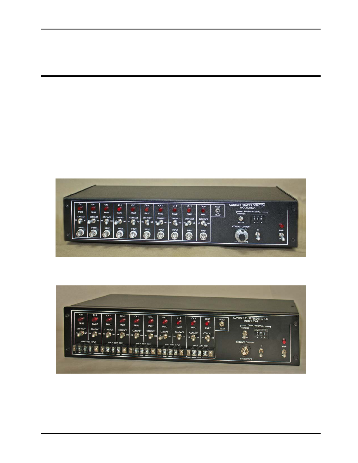
The 850A/B Contact Chatter Detector (Figures 1-1 and 1-2) is designed to
provide a means of monitoring the continuity of switch or relay contacts while
being subjected to environmental stress. The unit has 10 channels each with a
separate current source to activate the contacts. Contact current dial and X1–
X0.1 switch sets the current of all the channels simultaneously for 0.1 to 11
milliamps.
The difference between the two models is that the 850A uses BNCs for the
channel inputs and the 850B uses screw terminals.
Figure 1-1. Trig-Tek 850A Contact Chatter Detector
Figure 1-2. Trig-Tek 850B Contact Chatter Detector
Timing Interval Controls provide for setting from 1 to 999 microseconds or 1
999 milliseconds for the maximum time a discontinuity can exist. Each channel
has a FAULT LED which will illuminate if a discontinuity exists for a long er period
to
Astronics Test Systems Introduction 1-1
Artisan Technology Group - Quality Instrumentation ... Guaranteed | (888) 88-SOURCE | www.artisantg.com
Page 11

850A/B User Manual Publication No. 980972 Rev. B
of time than is set in by the Timing Interval Switch. The LED will remain
illuminated until reset either by the front panel reset switch or remotely via a reset
terminal. The unit has a terminal strip where the FAULT condition of each channel
can be recorded Low "NO FAULT" o r HIGH "FAULT."
Either Normally Closed (NC) or Normally Open (NO) contacts can be monitored.
A toggle switch on each channel permits selection of NC or NO type contacts.
Specifications
Controls
Channel Inputs (10 each)
Current Source Compliance 3 Volt (maximum).
Current Source Accuracy ±3% FS.
Timing Interval Accuracy Setting ±5 LSB.
Fault Reset Terminal Permits FAULT Reset from r em ote location.
Fault Output Terminals
Power Switch Turns Power ON or OFF.
Contact Current Dial
BNC-type connectors (850A)
Terminal interface (850B)
Provide a 12 Volt for “Fault” and 0 for “NO
Fault” for each channel.
Permits continuous setting of 1-11.
Operates in conjunction with the X1–X0.1
switch to provide 1 to 11 milliamps current
through the contact being t ested.
X1–X0.1 Swit ch Multiplies the current dial by X1 or X0.1
Timing Interval
MICROSEC-MILLISEC Switch
Timing Interval
001-999 Thumbwheel Switch
FAULT Reset Switch Resets all FAULT LED'S when depressed.
Introduction 1-2 Astronics Test Systems
Artisan Technology Group - Quality Instrumentation ... Guaranteed | (888) 88-SOURCE | www.artisantg.com
Toggle switch to select either microseconds
or milliseconds as the time interval.
Works in conjunction with the MICROSEC-
MlLLISEC switch to select 001 to 999 either
microsecond or millisecond time interval.
Page 12

Publication No. 980972 Rev. B 850A/B User Manual
Indicators
Power
Power LED
FAULT LEDs (10 ea.)
Power
Illuminates when power is applied to the
circuitry.
One for each channel. If a fault for the
channel occurs, the LED will illuminate and
remain on until the RESET s witc h is
depressed.
Operates from either 117 or 234 Volt RMS
AC power 50 or 60 Hz at approximately 15
watts.
Astronics Test Systems Introduction 1-3
Artisan Technology Group - Quality Instrumentation ... Guaranteed | (888) 88-SOURCE | www.artisantg.com
Page 13

850A/B User Manual Publication No. 980972 Rev. B
This page intentionally left blank.
Introduction 1-4 Astronics Test Systems
Artisan Technology Group - Quality Instrumentation ... Guaranteed | (888) 88-SOURCE | www.artisantg.com
Page 14

Publication No. 980972 Rev. B 850A/B User Manual
Chapter 2
Operation
The 850A/B Contact Chatter Detector contains t en contact monitors in a chassis
19 inches wide by 3-1/2 inches high and 8 inches deep.
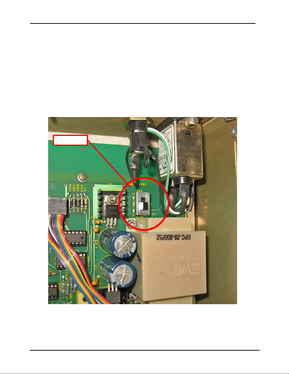
The unit operates using either 117 or 234 Volts RMS power. The switch S1 next
to the transformer (cover must be removed to view, see Figure 2-1) is mark ed 117
and 234. Set S1 to the appropriate pos ition for the power that is to be used.
Damage can be caus ed to the circuit ry if S1 is in the 117 posit ion and 234 V RMS
AC power is applied. With S1 set properly, apply the AC power and the unit is
ready to operate.
Current Setting
Before connecting any contact to the Contact Chatter Detector, set the current
that will flow in the contact. Damage could be caused if the current was set higher
than the contact current rating. The current is set between 0.1 to 11 millliamps
using the contact current dial and the X1–X0.1 switch to provide two ranges.
When the X 1–X0.1 switch is in the X0.1 position the dial sets 0. 1 to 1.1 milliamps
and the X1 position provides 1 to 11 milliamps. The current setting is for all ten
channels. To prevent damage to the contacts each channel voltage is clamped
below 3 Volts.
Time Interval Switch Settings
The Time Interval Switches set the time discontinuity can exist (in a NC contact)
before it is considered a FAULT, for a NO contact the opposite or closure for
longer than the set time interval would constitute a FAULT. T he time interval can
be set from 1 to 999 microseconds or 1 to 999 milliseconds using t he three digit
thumb switch in conjunction with the MICROSEC-MILLISEC switch. T he accur acy
is the setting ±3 LSD. These switches should be set to the appropriate setting for
the contact or contacts being m onit or ed.
Contact Connections and Switches
Connect the contact to be monitored to a channel input BNC (850A) or terminal
(850B). Set the Contact Switch to the required position NC if the contact is in the
closed position and NO if the contact is being t ested in the open position.
Astronics Test Systems Operation 2-1
Artisan Technology Group - Quality Instrumentation ... Guaranteed | (888) 88-SOURCE | www.artisantg.com
Page 15
850A/B User Manual Publication No. 980972 Rev. B
Switch S1
Fault
When a NC (Normally Closed) contact has a discontinuity longer than the set in
time interval, it is a FAULT, for NO (Normally Open) contact continuit y for a period
longer than the set in t ime interval constitutes a fault. When a FAULT is detected
the FAULT LED for that channel illuminates and a +12 V signal is present on the
FAULT output terminal on the rear panel. To remove the f ault the FAULT RESET
switch should be depressed, this removes the fault from all channels. The FAULT
RESET can be accomplished remotely by applying +12 volts to the RESET
terminal on the rear panel.
Figure 2-1. Switch S1 – Input Voltage Setting
Operation 2-2 Astronics Test Systems
Artisan Technology Group - Quality Instrumentation ... Guaranteed | (888) 88-SOURCE | www.artisantg.com
Page 16
Publication No. 980972 Rev. B 850A/B User Manual
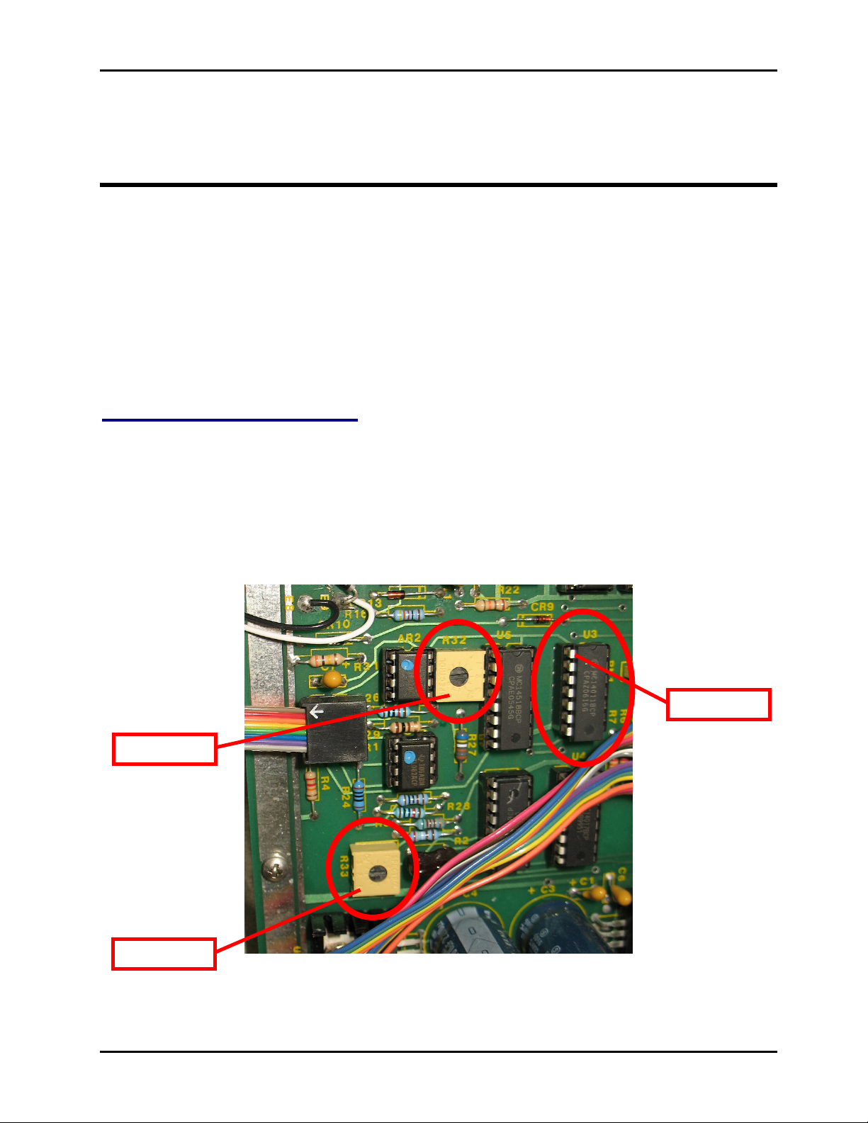
Pin 1, U3
R32
R33
Chapter 3
Calibration
The circuitry of the 850A/B Contact Chatter Detector is stable and should require
calibration only in the case of part failure. Astronics Test Systems recommends a
12-month calibration period or longer.
Refer to Figure 3-1 for both calibration adjustments. Remove top cover of the
850A/B to access components.
Timing Interval Adjustment
1. Connect a frequency counter to Pin 3 of U3 (Figure 3-1).
2. Set the MICROSEC-MILLISEC Switch to MICROSEC.
3. Set the timing adjust R33 f or an indicat ion of 1 MHZ ±10 kHz.
4. Place the MICROSEC-MILLISEC switch to MILLISEC.
5. The counter should indicate 1000 ±10 Hz.
Figure 3-1. Calibration Adjustments
Astronics Test Systems Calibration 3-1
Artisan Technology Group - Quality Instrumentation ... Guaranteed | (888) 88-SOURCE | www.artisantg.com
Page 17

850A/B User Manual Publication No. 980972 Rev. B
Contact Current Adjustment
1. Connect a current meter to Channel 1 Input. Set to read up to 11 milliamps.
2. Place the X1-X0.1 switch to X1.
3. Place the CONTACT CURRENT DIAL to 10.
4. Set the full-scale current adjust R32 for 10 ±.01 milliamps indication on the
current meter.
5. Connect the current m eter to each of the ot her nine channels and get 10 ±0.2
milliamps indication.
6. Place the X1-X0.1 Switch to X0.1.
7. All channels should indicate 1.0 ±0. 1 milliamps.
8. Set dial to 5, and X1-X0.1 Switch to X1.
9. All channels should indicate 5.0 ±0.1 milliamps.
Calibration 3-2 Astronics Test Systems
Artisan Technology Group - Quality Instrumentation ... Guaranteed | (888) 88-SOURCE | www.artisantg.com
Page 18

Artisan Technology Group is your source for quality
new and certied-used/pre-owned equipment
• FAST SHIPPING AND
DELIVERY
• TENS OF THOUSANDS OF
IN-STOCK ITEMS
• EQUIPMENT DEMOS
• HUNDREDS OF
MANUFACTURERS
SUPPORTED
• LEASING/MONTHLY
RENTALS
• ITAR CERTIFIED
SECURE ASSET SOLUTIONS
SERVICE CENTER REPAIRS
Experienced engineers and technicians on staff
at our full-service, in-house repair center
Instra
Remotely inspect equipment before purchasing with
our interactive website at www.instraview.com
Contact us: (888) 88-SOURCE | [email protected] | www.artisantg.com
SM
REMOTE INSPECTION
View
WE BUY USED EQUIPMENT
Sell your excess, underutilized, and idle used equipment
We also offer credit for buy-backs and trade-ins
www.artisantg.com/WeBuyEquipment
LOOKING FOR MORE INFORMATION?
Visit us on the web at www.artisantg.com for more
information on price quotations, drivers, technical
specications, manuals, and documentation
 Loading...