

Page 1

Trig-Tek™
530B
Tracking Filter
User Manual
Publication No. 98 0 974 Rev. B
Astronics Test Systems Inc.
4 Goodyear, Irvine, CA 92618
Tel: (800) 722-2528, (949) 859-8999; Fax: (949) 859-7139
[email protected] http://www.astronicstestsystems.com
Copyright 2011 by Astronics Test Systems Inc. Printed in the United States of America. All rights reserved.
This book or parts thereof may not be reproduced in any form without written permission of the publisher.
Page 2

THANK YOU FOR PURCHASING THIS
ASTRONICS TEST SYSTEMS PRODUCT
For this product, or any other Astr onics Test Systems produc t that incorporat es software drivers,
you may access our web site to verify and/or download the latest driver versions. The web
address for driver downloads is:
http://www.astronicstestsystems.com/support/downloads
If you have any questions about software driver downloads or our privacy policy, please contact
us at:
WARRANTY STATEMENT
All Astronics Test Systems products are designed to exacting standards and manufac t ur ed in full
compliance to our AS9100 Quality Management System processes.
This warranty does not apply to defects resulting f rom any modification(s) of any product or part
without Astronics Test System s express written consent, or misuse of any product or part. The
warranty also does not apply to fuses, software, non-rechargeable batteries, damage from
battery leakage, or problems arising f rom normal wear, such as m echanical r elay life, or failure to
follow instructions.
This warranty is in lieu of all other warranties, expressed or implied, including any implied
warranty of merchantability or fitness for a particular use. The remedies provided herein are
buyer’s sole and exclusive remedies.
For the specific terms of your standard warranty, contact Customer Support . Please have the
following information available to facilitate service.
1. Product serial number
2. Product model number
3. Your company and contact information
You may contact Customer Support by:
Page 3

RETURN OF PRODUCT
Authorization is required from Astronics Test Systems before you send us your product or sub-ass embly for
service or calibration. Call or contac t Custom er Support at 1-800-722-3262 or 1-949-859-8999 or via fax at
1-949-859-7139. We can also be reached at: [email protected].
If the original packing material is unavailable, ship the product or sub-assembly in an ESD shielding bag and
use appropriate packing materials to surround and protect the product.
PROPRIETARY NOTICE
This document and the technic al data her ein disc losed, ar e propr ietary to Astronics Test Systems, and shall
not, without express written permission of Astronics Test Systems, be used in whole or in part to solicit
quotations from a competitive source or used for manufacture by anyone other than Astronics Test
Systems. The information herein has been developed at private expense, and may only be used for
operation and maintenance referenc e purposes or for purposes of engineering evaluation and incorporation
into technical specifications and other documents which specify procurement of products from Astronics
Test Syste ms.
TRADEMARKS AND SERVICE MARKS
All trademarks and service marks used in this document are the property of their respective owners.
• Racal Instruments, Talon Instruments, Trig-Tek, ActivATE, Adapt-A-Switch, N-GEN, and PAW S are
trademarks of Astronics Test Systems in the United States.
DISCLAIMER
Buyer acknowledges and agrees that it is responsible for the operation of the goods purchased and should
ensure that they are used properly and in accordance with this document and any other instructions
provided by Seller. Astronics Test Systems products are not specifically designed, manufactured or
intended to be used as parts, assemblies or components in planning, construction, maintenance or
operation of a nuclear facility, or in life support or safety critical applications in which the failure of the
Astronics Test Systems product could create a situation where personal injury or death could occur. Should
Buyer purchase Astronics Test Systems product for such unintended application, Buyer shall indemnify and
hold Astronics Test Systems, its officers, employees, subsidiaries, affiliates and distributors harmless
against all claims arising out of a claim for personal injury or death associated with such unintended use.
Page 4
This equipment contains voltage hazardous to
prong adapter. This will defeat the protective feature of the third
FOR YOUR SAFETY
Before undertaking any troubleshooting, maintenance or exploratory procedure, read carefully the
WARNINGS and CAUTION notices.
human life and safety, and is capable of inflicting
If this instrument is to be powered f rom the AC line (mains) through an autotransform er,
ensure the common connector is connected to the neutral (earth pole) of the power
supply.
personal injury.
Before operating the unit, ensure the c onductor (green wire) is connected to the gr ound
(earth) conductor of the power outlet. Do not use a two-conductor extension cord or a
three-prong/twoconductor in the power cord.
Maintenance and calibration procedures sometimes call for operation of the unit with
power applied and protective covers removed. Read the procedur es and heed warnings
to avoid “live” circuit points.
Before operating this instrument:
1. Ensure the proper fuse is in place for the power source to operate.
2. Ensure all other devices connected to or in proximity to this instrument are properly grounded or
connected to the protective third-wire earth ground.
If the instrument:
- fails to operate satisfactorily
- shows visible damage
- has been stored under unfavorable conditions
- has sustained stress
Do not operate until performance is checked by qualified personnel.
Page 5

Publication No. 980974 Rev. B 530B User Manual
Table of Contents
Chapter 1 ......................................................................................................................... 1-1
Introduction ..................................................................................................................... 1-1
System Description ........................................................................................................................ 1-2
General....................................................................................................................................... 1-2
Carrier Generator ....................................................................................................................... 1-3
Analyzer...................................................................................................................................... 1-3
System Specifications .................................................................................................................... 1-3
Reference Input .......................................................................................................................... 1-3
Data Input ................................................................................................................................... 1-4
Filtered Signal Output ................................................................................................................. 1-4
DC of Level (Linear) ................................................................................................................... 1-4
DC of Frequency (Linear) ........................................................................................................... 1-5
DC of Level (Log) Optional ......................................................................................................... 1-5
DC of Frequency (Log) ............................................................................................................... 1-5
Bandwidth ................................................................................................................................... 1-5
Time Constant ............................................................................................................................ 1-6
Controls ...................................................................................................................................... 1-6
Indicators .................................................................................................................................... 1-6
Power ......................................................................................................................................... 1-7
Size ............................................................................................................................................ 1-7
Cabinets (required) .................................................................................................................... 1-7
Chapter 2 ......................................................................................................................... 2-1
Operation ......................................................................................................................... 2-1
Meter Input Switch ...................................................................................................................... 2-1
Range FS Volts Switch ............................................................................................................... 2-1
DC Output TC Switch ................................................................................................................. 2-1
MANUAL-AUTO (LIMIT) Switch and BW Hz Thumb Switch...................................................... 2-2
OVER LOAD Light...................................................................................................................... 2-2
ERROR Light.............................................................................................................................. 2-2
DVM Front Panel Meter.............................................................................................................. 2-2
Wide Bandwidth Filter (Optional) ............................................................................................... 2-2
Chapter 3 ......................................................................................................................... 3-1
Performance Test ............................................................................................................ 3-1
Test Equipment .......................................................................................................................... 3-1
Switch Setttings .......................................................................................................................... 3-1
Performance Test Procedure ..................................................................................................... 3-1
Checking the Bandwidth............................................................................................................. 3-3
Astronics Test Systems i
Page 6

530B User Manual Publication No. 980974 Rev. B
Chapter 4 ........................................................................................................................ 4-1
Calibration Procedure .................................................................................................... 4-1
Test Equipment ...........................................................................................................................4-1
Test Procedure ...........................................................................................................................4-1
DC of Frequency Adjustments (Linear) ......................................................................................4-2
DC Zero Adjustments (W15B) ....................................................................................................4-3
FS Range Adjust .........................................................................................................................4-3
Log of Adjustments .....................................................................................................................4-4
Bandwidth Adjustments (W 15B) ................................................................................................4-5
.
ii Astronics Test Systems
Page 7

Publication No. 980974 Rev. B 530B User Manual
List of Figures
Figure 1-1, 530B Tracking Filter ......................................................................................................... 1-2
Figure 4-1, Adjustment Resistor Locations ........................................................................................ 4-2
Figure 4-2, Front Panel Meter Circuit Board Adjustment ................................................................... 4-4
Astronics Test Systems iii
Page 8

530B User Manual Publication No. 980974 Rev. B
This page was left intentionally blank.
iv Astronics Test Systems
Page 9
Publication No. 980974 Rev. B 530B User Manual
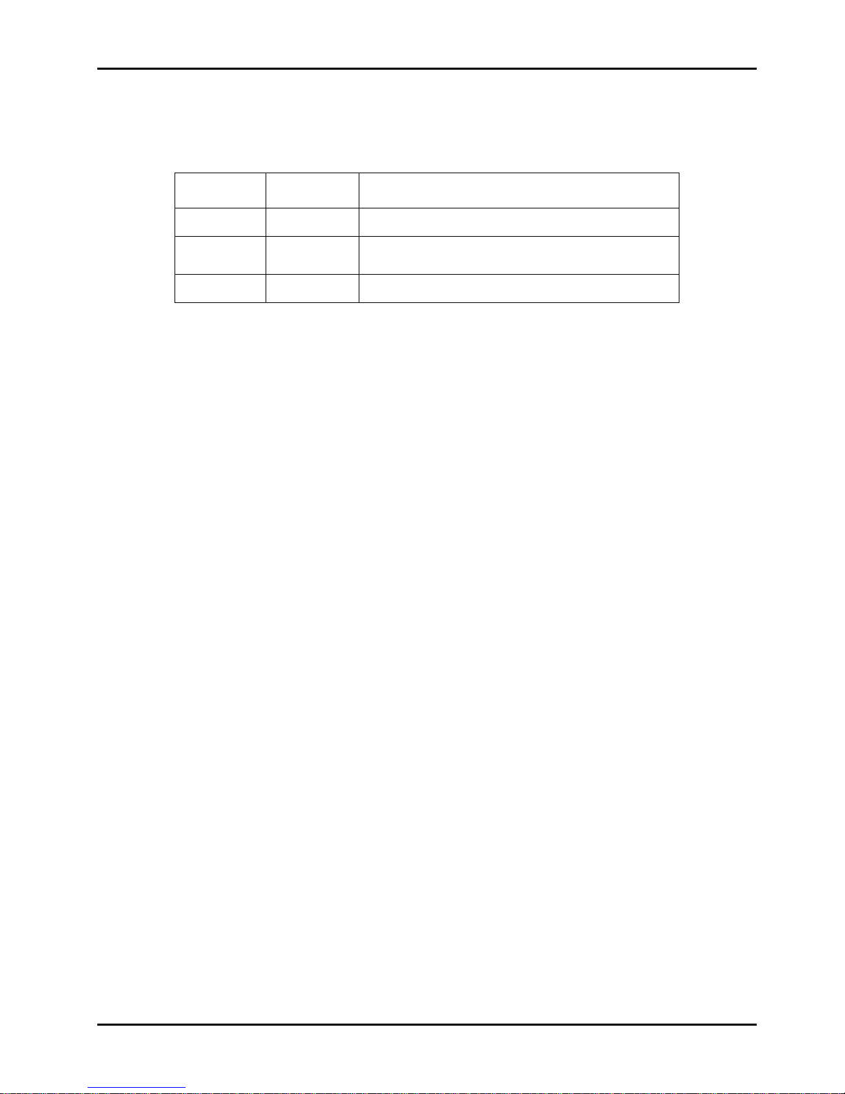
DOCUMENT CHANGE HISTORY
Revision Date Description of Change
A 03/31/2011 Document Control release
B 01/28/2012
Revised per ECN02268 updating bandwidth
numbers in Chapter 3.
Astronics Test Systems v
Page 10

530B User Manual Publication No. 980974 Rev. B
This page was left intentionally blank.
vi Astronics Test Systems
Page 11

Publication No. 980974 Rev. B 530B User Manual
Chapter 1
Introduction
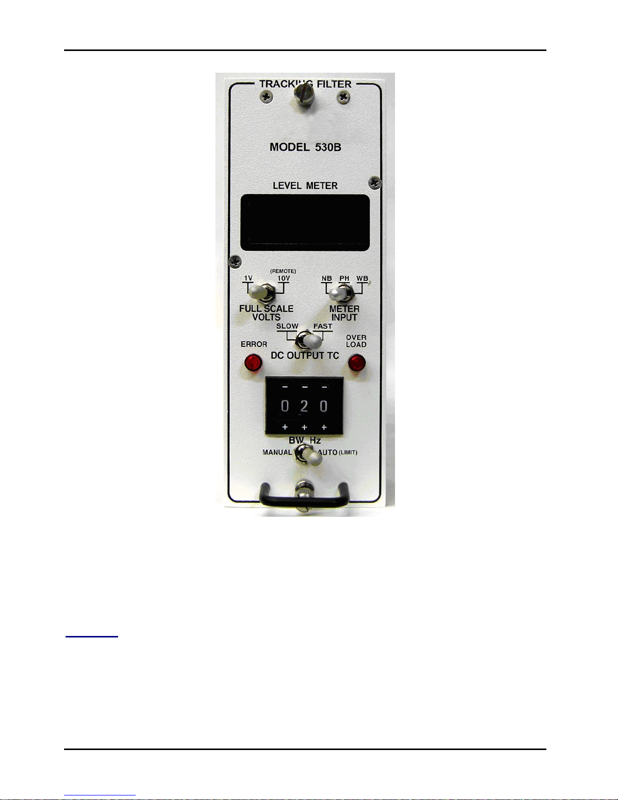
The 530B Tracking Filter (Figure 1-1) accepts a complex signal at its input and
provides a clean filtered signal at its output at frequencies between 5 Hz and
10,000 Hz. It automat ically tracks a ref erence input sig nal and tunes the center of
the filter to that frequency. The r eference signal wave form can vary from a sine
wave to a short duration pulse. Filter bandwidth can be adjusted manually or
automatically via a front panel switch.
When in the MANUAL position, a thumb switch allows the filter bandwidth to be
set from 001 Hz to 299 Hz. This bandwidth will remain constant over the entire
frequency range. When switched to Auto (limit), the filter will automatically
maintain a bandwidth, which is 10% of the Reference INPUT frequency until
limited by the value set on t he BW HZ thum b switch. For example, if the sett ing is
50 Hz, the filter BW will stay at 10% of the reference frequency until it reaches
500 Hz, where the bandwidth would be 50 Hz. Thereafter, as the reference
frequency increases, the filter bandwidth would remain at its limit of 50 Hz.
A front panel digital meter allows monitoring NB -PH-W B signal levels. It is in true
RMS units, and has two full-scale settings of 1 or 10 VRMS. The PH (PHASE) is
degrees. There are two front panel LED’s, ERROR and OVERLOAD. The
ERROR LED illuminates when a wrong reference signal is applied. The
OVERLOAD LED illuminates if the wideband input or filtered output is exceeded.
In addition to the filtered output, the 530B also provides rear panel outputs for
linear and log DC of frequency as well as linear DC of level. A rear panel terminal
strip provides TTL signals f or overload and lock conditions as well as a means to
remotely switch the full-scale range between 1 or 10 Volts.
Features include:
• Bandwidths from 1 Hz to 299 Hz
• Fixed or Variable Bandwidths
• 5 to 10,000Hz Frequency Range
• True RMS Meter (NB-PH-WB)
• Linear and Log DC of Frequency
• Linear DC of Level (or log) (Both Narrow and Wide Band)
• 115 or 230 VRMS Power
Astronics Test Systems Introduction 1-1
Page 12
530B User Manual Publication No. 980974 Rev. B
System Description
General
The 530B Tracking Filter has two major parts. The Carrier Generator provides
tuning to the analyzer port ion and generates a linear and logarithmic DC voltage
proportional to frequency.
The Analyzer part accomplishes the filtering and provides an AC Filtered output
and both linear and logarithmic DC voltages proportional to the level.
Introduction 1-2 Astronics Test Systems
Figure 1-1, 530B Tracking Filter
Page 13

Publication No. 980974 Rev. B 530B User Manual
Carrier Generator
The Carrier Generat or uses a phase-lock-loop to track the r eference input signal
frequency. The reference frequency is multiplied by 256 and a binary divider
residing in the W 15B module counts it down to X1. The output f rom the divider is
used to address two read-only memories, each programmed with a sine wave,
one 90º phase shift ed from the other. T he SIN and COS outputs of the mem ories
are used to tune the Analyzer. A digital counter output to analog converter
provides a linear DC output. The log of frequency is accomplished in the DSP
chip and brought out via a separate Digital to Analog Converter.
Analyzer
The Data Input first g oes to a selectable gain circuit which sets the g ain for either
1 Volt or 10 V RMS full scale as selected by the RANGE switch. The scaled
signal goes to the 0º and 90º MDAC (in the W15) where the signal is mixed with
the carrier signals and translated to a DC IF ( Intermediate Frequency).
The DC plus side band signal is filtered by the variable Low Pass filter, and then is
again translated to the original tuned f requency. This reg enerated signal is at the
output of the summing circuit. The level is scaled and brought out at the
FILTERED output jack. The W B RMS level of the input is converted to DC by a
TRMS converter, and a second for the narrow bandwidth (NB) TRMS converter.
The METER INPUT switch selects either the NB, PH (phase) or W B LEVEL to the
meter input. The log of the WB and NB levels are derived and either can be
brought out on the WB and NB Level output jacks instead of the linear outputs
selected by an internal switch (S3) for the W B or S4 for the NB outputs. PH or
WB outputs ar e select ed to the WB LEVEL output jack by (S2).
System Specifications
Reference Input
Impedance 500 k Ohms
Frequency Response 5 Hz to 10,000 Hz
Level 50 mV Pk-Pk to 100 V Pk-Pk
Waveform
Connector BNC (isolated)
Sine, Triangle, Square or Pulse (pulse
width 25 μs minimum).
Astronics Test Systems Introduction 1-3
Page 14
530B User Manual Publication No. 980974 Rev. B
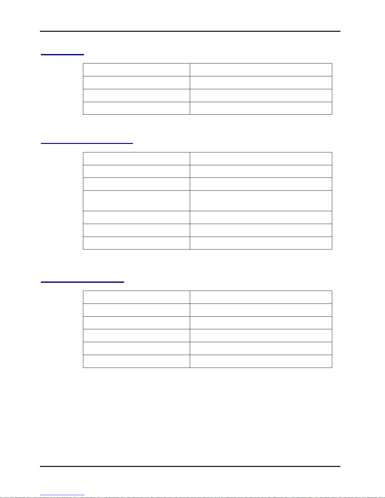
Data Input
Impedance 500 k Ohms
Frequency 5 Hz to 10,000 Hz
Level 1 or 10 VRMS full scale (FS)
Connector BNC (Low side at signal ground)
Filtered Signa l Output
Impedance <50 Ohms
Frequency 5 Hz to 10,000 Hz
Level 0 to 10 Volts RMS
Distortion
Accuracy ±3% of Reading, ±0.5% FS
Dynamic Range 50dB
Connector BNC (Low side at signal ground)
DC of Level (Linear)
Impedance <50 Ohms
Maximum Out WBW 10 Volts FS
Maximum Out NBW 10 Volts FS
Accuracy ±3% of Reading, ±0.5% FS
Dynamic Range 60dB
Connector BNC (Low side at signal ground)
5 to 10,000 Hz, <5%
20 to 5,000 Hz, <2%
Introduction 1-4 Astronics Test Systems
Page 15
Publication No. 980974 Rev. B 530B User Manual
DC of Frequency (Linear)
Impedance <50 Ohms
Maximum Output 10 Volts (10,000 Hz)
Sensitivity 0.5 mV/Hz
Accuracy ±1% of Reading, ±0.1% FS
Connector BNC (Low side at signal ground)
DC of Level (Log) Optional
Impedance <50 Ohms
Maximum Output 10 Volts = 0dB
Sensitivity 125 mV/dB
Dynamic Range 50dB
WBW/NBW (Optional)
Noise 50dB
Connector BNC (Low side at signal ground)
DC of Frequency (Log)
Impedance <50 Ohms
Maximum Output 10 Volts
Conformity 0.5 dB
Sensitivity 125 mV/dB
Connector BNC (Low side at signal ground)
Bandwidth
Accuracy of Dial ±3%
Filter Shape 5-Section Bessell
Astronics Test Systems Introduction 1-5
Page 16
530B User Manual Publication No. 980974 Rev. B
Time Constant
Fast Slow
Narrow Bandwidth 0.3 sec 1 sec.
Wide Bandwidth 0.3 sec. 1 sec.
Controls
Range FS Volts Switch Selects 1 V or 10 V FS Input Range.
Meter Input Switch Selects WB, NB amplitude, or PH (phase).
Indicators
DC Output TC Switch
Manual Auto (Limit) Switch Selects Auto BW or Manual BW . In Auto
Filter IN-OUT Switc h Located on the front panel of t he chas sis,
Level Meter 3-1/2 Digit meter indicating level in Volts
OVERLOAD LED LED illuminates if input to tracking filter is
Selects SLOW or FAST time constant for
meter (and DC outputs).
(Limit) mode, Bandwidth is 10% of t he REF
frequency.
In the MANUAL mode, a fixed bandwidth is
selected via the front panel BW Hz thumb
switch.
allows the signal to pass through the
tracking filter in t he Filter position and to
bypass the tracking filter in t he Bypass
position.
RMS or Degrees.
too high for selected rang e, or if output
from filter to meter is too high.
ERROR LED LED illuminates when an in-correct signal is
Introduction 1-6 Astronics Test Systems
applied to the REF Input.
Page 17

Publication No. 980974 Rev. B 530B User Manual
Power
115 or 230 Volts, 50-400 Hz.
Size
7” High x 2.7” W ide x 13” Deep.
Cabinets (required)
Single-Module 4220
Six-Module 19” Rack 4200
Optional Plug-in HP and LP Filter Assy 1697-1 is
available with 3-selectable High Pass and
3-selectable Low Pass Filters. Frequency
cutoffs are: HP-5, 30 or 70 Hz, LP-5000,
10,000 or 20,000Hz.
Astronics Test Systems Introduction 1-7
Page 18

530B User Manual Publication No. 980974 Rev. B
This page was left intentionally blank.
Introduction 1-8 Astronics Test Systems
Page 19

Publication No. 980974 Rev. B 530B User Manual
Chapter 2
Operation
The 530B Tracking Filter is designed to require little operator attention. The
front panel has a METER INPUT switch, RANGE FS VOLTS switch, DC
OUTPUT T C s witc h, MANUAL-AUTO (Limit) switch (in conjunction with a BW HZ
thumb switch), an OVER LOAD LED, an ERROR LED, and a 3-1/2 Digit DVM
display. A description of each follows.
Meter Input Switch
The Meter INPUT Switch is a three-position toggle switch to select either the NB
(narrow bandwidth) or WB (wide bandwidth) TRMS DC output or the PH (phas e)
DEG (degrees). The bandwidth of the NB input is determined by the BW HZ
thumb switch 001 to 299 in 1 Hz steps. The WB input has a HP-LP Filter
Assembly option with settings available to filter the WB output. See WIDE
BANDWIDTH FILT ER at the end of this section. T he PH DEG selects the DC of
Phase shift between the REF and DATA signal to the meter .
Range FS Volts Switch
The RANGE FS VOLTS Switc h is a two-position toggle switch to select either 1
or 10 VRMS FS at the DATA INPUT jack, and at the FS met er range. The 1 or
10 VRMS FS range can be selected remotely by a ground on the terminal
labeled “RANGE”; when the remote selection is used, the RANGE switch must
be in the 10V (REMOTE) position.
DC Output TC Switch
The DC OUTPUT TC Switch is a two-position toggle switch to select either a
SLOW or FAST time constant for the NB and WB DC outputs and meter
response. The DC OUTPUT TC switch changes the time constant of both NB
and WB TRMS detectors s imult aneously.
Astronics Test Systems Operation 2-1
Page 20

530B User Manual Publication No. 980974 Rev. B
MANUAL-AUTO (LIMIT) Swi t c h a nd BW Hz Thumb Switch
This two-position toggle switch below the BW Hz thumb switch selects either
MANUAL or AUTO (Limit). When the MANUAL position is selected, the BW Hz
thumb switch set s the filter bandwidth in 1 Hz steps to 299 Hz. W hen the AUTO
(Limit) is selected, the filter bandwidth is one-tenth the reference tuning
frequency. The bandwidth is 1 Hz with a reference frequency from 10 Hz and at
20 Hz; the bandwidth of the filter is 2 Hz and as the reference frequency
changes, will maintain 10% of the reference frequency until it reaches the
number of the BW Hz thumb switch limit set ting.
OVER LOAD Light
This indicator is a red LED labeled OVER LOAD. The OVER LOAD LED
illuminates when either the input or meter circuit is overloaded. When on, the
purpose of the LED is to alert the operat or that an overload condition exists and
the acquired data may not be valid.
ERROR Light
This indicator is a red LED labeled ERROR. The ERROR LED illuminates when
an incorrect signal is at the REF Input. Correct REF Input signal are ( levels of
50 mV–100 VRMS) with any reoccurring wave form (sine, square or triang le) .
DVM Front Panel Meter
The front panel DVM (digital voltmeter) is calibrated to indicate the DATA Input
level in TRMS units for the NB and WB settings and in degrees for the PH
(Phase).
Wide Bandwidth Filter (Optional)
A plug-in HP-LP Filter Assembly, part number 1697-1, is available to filter the
wide bandwidth detector input.
The filter assembly plugs into the A4 header on the main board and scr ews down
to two studs. The jumper between Pin 3 and Pin 6 of A4 must be removed
before installation. The filter assembly provides three switch-selectable low-pass
filter bandwidths of 5, 10 or 20 kHz, and three switch-selectable high-pass filter
bandwidths of 5, 30 and 70 Hz. The low-pass and high-pass filters are each
four-section Butterworth designs. Other filter bandwidths can be furnished on
special order.
Operation 2-2 Astronics Test Systems
Page 21

Publication No. 980974 Rev. B 530B User Manual
Chapter 3
Performance Test
The following procedure outlines a method of testing the 530B Tracking Filter.
The unit may be in a single-unit cabinet or the one that holds six (6) units. The
following procedure is for a single unit, and must be repeated f or each module. In
the event that a reading is out of t olerance, the unit will require calibration. (See
Chapter 4.)
Test Equipment
Note: Equivalent equipment can be substituted.
Multimeter Fluke 4588A
Generators (2) Trig-Tek 45EMD Portable Calibrator.
Switch Setttings
Place the FS RANGE switch to 10 V, the MANUAL-AUTO switch to MANUAL, the
BW HZ thum b switch to 005, and the DC OUTPUT T C switch to SLOW. Connect
the power cord of the rack assembly into the power line and turn the POWER
switch at the left side of the rack to ON.
Performance Test Procedure
1. Connect the generator to the REF INPUT j ac k.
2. Set the generator for a frequency of 10,000 ±5 Hz and a level of
approximately 1 VRMS.
3. Connect the DC voltmeter to the LIN DC of FREQ OUTPUT jack.
4. Observe a 10 ±0.10 Volt indication on the DC voltmeter.
(The ERROR LED should not be illuminated).
5. Set the generator for a frequency of 10 ±0.1 Hz.
6. Observe a 10 ±4 mV indication on the DC voltmeter.
7. Connect the DC voltmeter to the LOG DC of FREQ j ac k.
8. Set the generator for a frequency of 10,000 ±20 Hz.
9. Observe an indication of 10.00 ±0.50 V on the DC voltmeter.
10. Set the generator for a frequency of 100 ±0.1Hz.
Astronics Test Systems Performance Test 3-1
Page 22

530B User Manual Publication No. 980974 Rev. B
11. Observe an indication of 5.00 ±0.50 V on the DC voltmeter.
12. Connect the generator to both the REF input and DATA input.
13. Set the generator for a frequency of approximately 500 Hz at a level of
10.00 ±0.03 VRMS.
14. Connect the DC voltmeter to the NB Output jack.
15. Place the METER INPUT switch to NB.
16. Observe a 10.00 ±0.25 V indication on the DC voltmeter.
17. Observe that the front panel meter indicates 10.00 ±0.25 VRMS.
18. Place the METER INPUT switch to WB.
19. Connect the DC Voltmeter to the WBDC OUT PUT jack.
20. Observe an indication of 10.00 ±0.25 V on the DC voltmeter.
21. Observe that the front panel meter indicates 10.00 ±0.25.
22. Connect the AC Voltmeter to the FILTER OUTPUT jack.
23. Observe a 10.00 ±0.5 VRMS indication on the AC voltmeter.
24. Set the generator level for 1 ±0.005 VRMS.
25. Connect the DC voltmeter to the NB OUTPUT jack and the RANGE Switch
to 1 VRMS.
26. Place the METER INPUT switch to NB.
27. Observe a 10.00 ±0.25 Volt indication on the DC Voltmeter. The front
panel meter should indicate 1.00 ±0.03.
28. Connect the AC Voltmeter to the FILTER output jack .
29. Observe an indication of 1.00 ±0.05 VRMS on the AC voltmeter.
30. Set the generator frequency for 5 Hz.
31. Observe an indication of 1.000 ±0.05 on the front panel meter.
32. Set the generator frequency for 10,000Hz.
33. Observe an indication of 1 ±0.05 VRMS on the AC voltmeter. The front
panel meter should indicate 1.000 ±0.05.
Performance Test 3-2 Astronics Test Systems
Page 23

Publication No. 980974 Rev. B 530B User Manual
Checking the Bandwidth
Two generators are needed for perf or m ing the following test:
1. Connect generator #1 to the REF INPUT jack.
2. Set the generator #1 for appr oximately 1 VRMS level and for a frequency
of 500Hz.
3. Connect generator #2 to the DATA I NPUT j ac k.
4. Set the FS Range switch to 1 V, the METER INPUT switch in NB, the
MANUAL-AUTO switch to MANUAL and the BW Hz thumb switch to 002.
5. Set the frequency of generator #2 to 500 ±0.1 Hz and the level to 1.000
±0.005 VRMS.
6. The front panel meter should indicate 1.00 ±.03 VRMS.
7. Set generator #2 f or 501 Hz.
8. Observe 0.707 ±0.1 VRMS indication on the front panel DPM. (Note that
the front panel DPM indication may vary at 1 Hz rate around the
0.707 ±0.1 VRMS).
9. Set generator #2 f or 525 ±0.1 Hz.
10. Set BW HZ thumb switch to 050.
11. Observe a .0.707 ±0.1 VRMS indication on the front panel meter.
12. Place the BW Hz thumb switch to 010.
13. Connect generator #1 SQ WAVE O UT PUT t o the REF Input, and the
DATA Input. Set at 100 ±0.1 Hz.
14. Place METER INPUT Switch to PH (Phase).
15. Observe an indication of 0 ±5 degrees on the front panel m et er .
Astronics Test Systems Performance Test 3-3
Page 24

530B User Manual Publication No. 980974 Rev. B
This page was left intentionally blank.
Performance Test 3-4 Astronics Test Systems
Page 25

Publication No. 980974 Rev. B 530B User Manual
Chapter 4
Calibration Procedure
The 530B Tracking Filter module adj ustments are all accessible when the unit is
removed from the chassis. Use a power cord assembly TT-1535 and a 530B
board test assembly TT-1789 to accommodate bench testing the unit. Contact
Sales or Customer Support for information about these accessories. The
following procedure provides a means of sett ing each adjustment.
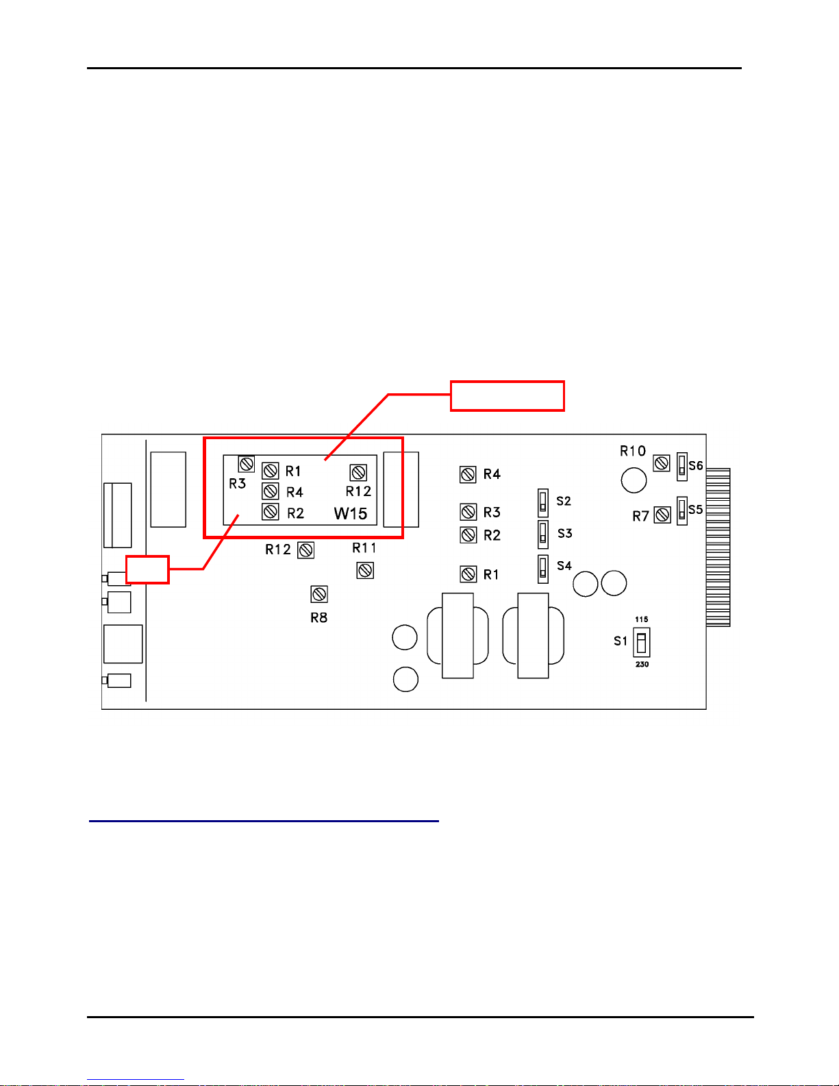
Refer to Figure 4-1 for locations of various potentiometers and switches on the
internal circuit board. Note that som e adjustments call out the pots on the at t ac hed
W15 boar d. Even though they may have the same resistor number, be sure to
adjust the correct resist or .
Test Equipment
Note: Equivalent equipment can be substituted.
Multimeter Fluke 4588A
Generators (2) Trig-Tek Portable Calibrator.
Oscilloscope
Power Cord Assembly Trig-Tek TT-1535.
Board Test Assembly Trig-Tek TT-1789.
Test Procedure
1. Remove the 530B module to be tested from t he cabinet .
WARNING
Damage can occur to the circuitry if the internal switch, S1, i s
set to the 115 position and 230 VRMS AC power is applied.
See Figure 4-1 for the location of S1.
2. Use the power cord assembly (TT-1535) to connect power to the module.
3. The inputs and outputs on the pins of the P1 connector are brought out on
BNC Connectors of the test assembly (TT-1789).
4. When the as sem bly is plugged onto P1, set the f ollowing on the front panel:
a. OUTPUT TC switc h to FAST
Astronics Test Systems Calibration Procedu re 4-1
Page 26
530B User Manual Publication No. 980974 Rev. B
W15 Board
C2
b. FS RANGE switch to 10 VRMS
c. METER I NP UT switch to NB
d. MANUAL-AUTO (Limit) s witc h to MANUAL
e. BW HZ thum b Switch to 010.
5. Ensure the following is set on the 530B main circuit board:
a. S2 to WB
b. S3 to LIN
c. S4 to LI N
d. S5 to OFF
e. S6 to SE
Figure 4-1, Adjustment Resistor Locations
DC of Frequency Adjustments (Linear)
1. Connect the generator to the REF INPUT j ac k, Pins 17 and 18 of P1.
2. Set the generator for a frequency of 10.000 ±10Hz and set for a level of
approximately 1 V.
3. Connect the DC voltmeter to the LIN DC of FREQ OUTPUT jack, Pin 8 of P1.
4. Set R1 (TACH FS ADJ) for 10.00 ±.05 V indication on the DC voltmeter.
5. Set the function generator for a frequency of 10 ±10 Hz.
Calibration Procedure 4-2 Astronics Test Systems
Page 27

Publication No. 980974 Rev. B 530B User Manual
6. Observe 10 ±2 mV indication on the DC voltmeter.
7. Set the function generator for frequency of 10.000 ±10 Hz.
8. Check the LIN DC of FREQ for 10.00 ±.05 V, connect the DC voltmeter to the
LOG DC of FREQ jack at Pin 15 of P1.
9. Set R2 (FS ADJ) for 10.00 ±.01 V indication on the DC voltmeter.
DC Zero Adjustments (W15B)
1. Connect the generator to the REFERENCE INPUT, Pin 17 and 18 of P1.
2. Set the generator for a frequency near 500 Hz and a level of approximately 1 V.
3. Short the DATA INPUT, Pins 13 and 16 of P1.
4. Connect the DC voltmeter to test point C2 (on the W15 boar d).
5. Set R1 (DC ADJ) for a 0 ±3 mV indication on the DC voltmeter.
6. Connect the DC voltmeter to test point S2.
7. Set R2 (DC ADJ) for a 0 ±3 mV indication on the DC voltmeter.
FS Range Adjust
1. Connect the generator to both of the REF and DATA INPUT jacks, Pins 17
and 18, and Pins 13 and 16 of P1.
2. Place the RANGE switch to 10 V.
3. Set the generator for a frequency of 500 Hz and a level of 10.00 ±.01 V.
4. Place the METER INPUT switc h to NB.
5. Connect the DC voltmeter to the NB OUTPUT jack, Pin 10 of P1.
6. Set R12 (NB FS ADJ) for a 10.00 ±0.02 V indication on the DC voltmeter.
7. Set the R1 (METER REF ADJ) on the front panel m et er boar d (Figure 4-2) for
an indication of 10.00 ±0.02 on the f r ont panel meter.
8. Place the METER INPUT switch to WB. Connect t he DC voltmeter to WB
OUTPUT, Pin 14 of P1.
9. Set R8 (WB FS ADJ) for a 10.00 ±.03 V indication on the DC voltmeter. (The
front panel DVM will indicate 10.00 ±0.10 VRMS).
10. Connect the AC voltmeter to the FILTER OUTPUT jack , Pins 11 and 9 of P1.
11. Set R4 (on the W15 board) for a 10.00 ±0.10 V indication on t he AC
voltmeter.
Astronics Test Systems Calibration Procedu re 4-3
Page 28
530B User Manual Publication No. 980974 Rev. B
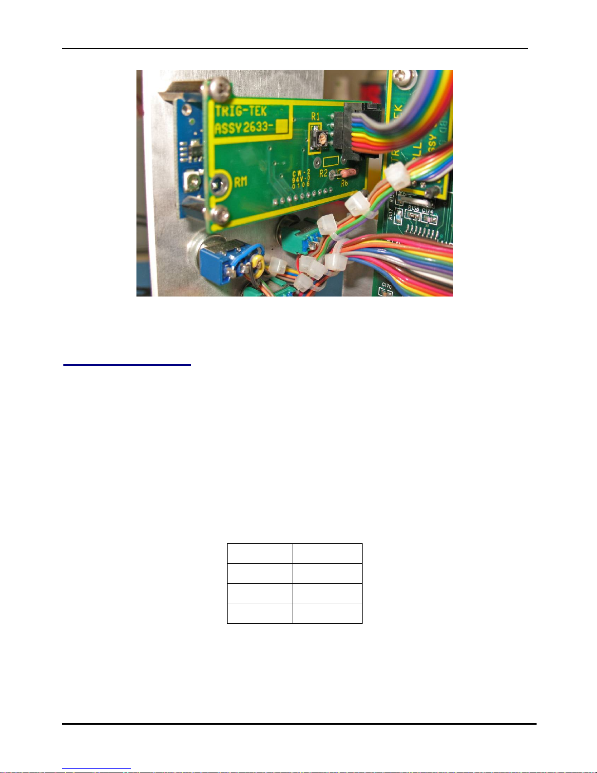
Figure 4-2, Front Panel Meter Circuit Board Adjustment
Log of Adjustments
1. Connect the DC voltmeter to the NB OUTPUT jack, pin 10 of P1.
2. Set internal switches S3 and S4 to LOG position, and S2 to WB.
3. Set the RANGE switch to 10V, and the generator for 10.00 ±.05 VRMS.
4. Set R3 (NB LOG ADJ) f or a 10. 00 ±0.1 V indication on the DC voltmeter.
5. Connect the DC voltmeter the WB OUTPUT jack, Pin 14 of P1.
6. Set R4 (WB LOG ADJ) for a 10.00 ±0.10 V indication on the DC voltmeter.
Note: High pass, low pass filt er par t num ber 1697-1 is not a Butterworth
filter. The spread between the –5% and –3dB poi nt s i s not calculated in the
usual way. Test to the follow i ng 3dB poi nt s ±10%.
HP LP
3.4 Hz 3.5 KHz
19.8 Hz 7 KHz
43 Hz
14.1 KHz
Calibration Procedure 4-4 Astronics Test Systems
Page 29

Publication No. 980974 Rev. B 530B User Manual
Bandwidth Adjustments ( W 1 5 B)
1. Connect generator #1 to the REF INPUT jack. Verify that the TC switch is in
SLOW.
2. Set the generator #1 for appr oximately 1 VRMS level and for a frequency of
1000 ±0.1 Hz.
3. Connect generator #2 to the DATA I NPUT j ac k.
4. Set the FS RANGE switch to 1 V RMS, the METER INPUT switch to NB, the
BANDWIDTH switch to MANUAL, and set the BW HZ thumb switch to 200.
5. Set the frequency of generator #2 to 1000 ±0.1 Hz and the level to for a 1. 000
±.01 volt indication on the LEVEL METER.
6. Set generator #2 f or 1100 ±0.1 Hz.
7. Set R3 (on the W15 board) for a .707 ±.050 VRMS indication on the front
panel LEVEL METER.
8. Set the generator #2 for 1001 ± 0.1 Hz.
9. Set the BW HZ thum b s witch to 002.
10. Look for a 0.707 ±.050 VRMS indication on the front panel meter.
(Note that it is normal f or the indication to vary upwards and downw ar ds
around this central value at a 1 Hz rate).
Astronics Test Systems Calibration Procedu re 4-5
Page 30

530B User Manual Publication No. 980974 Rev. B
This page was left intentionally blank.
Calibration Procedure 4-6 Astronics Test Systems
 Loading...