

Page 1
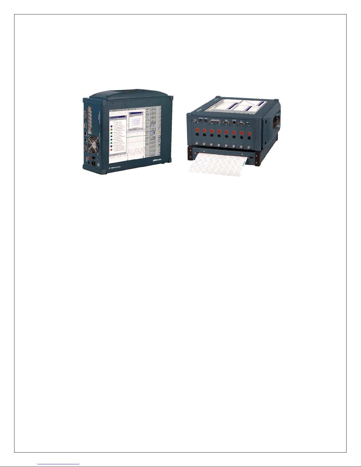
Dash 8Xe / Dash 8X
Data Acquisition Recorder
QUICK START GUIDE
Astro-Med, Incorporated: Test & Measurement Product Group
Astro-Med Industrial Park, 600 East Greenwich Ave., West Warwick, RI 02893
Toll-Free Phone: 877-867-9783 Phone: Fax: 401-822-2430
(1) Introduction
(2) Getting Started
(3) Hardware Overview
(4) Menus & Icons
(5) Using the Dash 8Xe / Dash 8X
(6) Setting Up the Display Appearance
(7) Amplifier Settings
(8) Sample Exercises
(9) Archiving Data Records
(10) Entering Engineering Units
(11) Powering Down
email: [email protected]
Part # 22834518 Version 1.1
Page 2
11.. IINNTTRROODDUUCCTTIIOONN
Thank you for choosing an Astro-Med data acquisition recorder. This Quick Start Guide was prepared to help you
become acquainted with your recorder as quickly as possible. We even include sample exercises so you can become
familiar with the basic operation.
This Quick Start Guide supports two models: The Dash 8Xe and the Dash 8X.
Throughout this guide, both models will be referred to as Dash 8Xe / Dash 8X.
The Dash 8Xe / Dash 8X is a powerful and versatile data acquisition recording system that provides the capability to
display, record, and review waveform data. The system uses up to eight plug-in modules for signal input connections.
Input modules are installed using the eight plug-in slots, which provide configuration flexibility for a variety of applications
and future growth.
Data samples from up to eight signals can be acquired at rates up to 200,000 samples per second and stream ed directly
to a high-capacity hard drive. Additionally, the Dash 8Xe / Dash 8X has a scope card option that adds four channels with
sample rates of up to five million samples per second.
The Dash 8Xe / Dash 8X utilizes a touch-screen as the main user interface. Many of the Dash 8Xe / Dash 8X control
icons are customizable, providing the capability to modify the display based on the needs of the user or application.
22.. GGEETTTTIINNGG SSTTAARRTTEEDD
Voltage Verification: The Dash 8Xe / Dash 8X has an auto-sensing power supply that operates from 100 – 250 VAC at
50 or 60 Hz. You do not have to set up any fuse block arrangement.
Connect AC Power Cord: Connect AC power cord to the side panel, then to an outlet.
Turn On Dash 8Xe / Dash 8X: When you turn on the Dash 8Xe / Dash 8X, the display will show various initialization
screens and then load in the last setup it had before it was powered down.
Signal Inputs: The Dash 8Xe / Dash 8X can record up to eight channels of analog signals. Signal type is dependent
upon the signal module used for each channel.
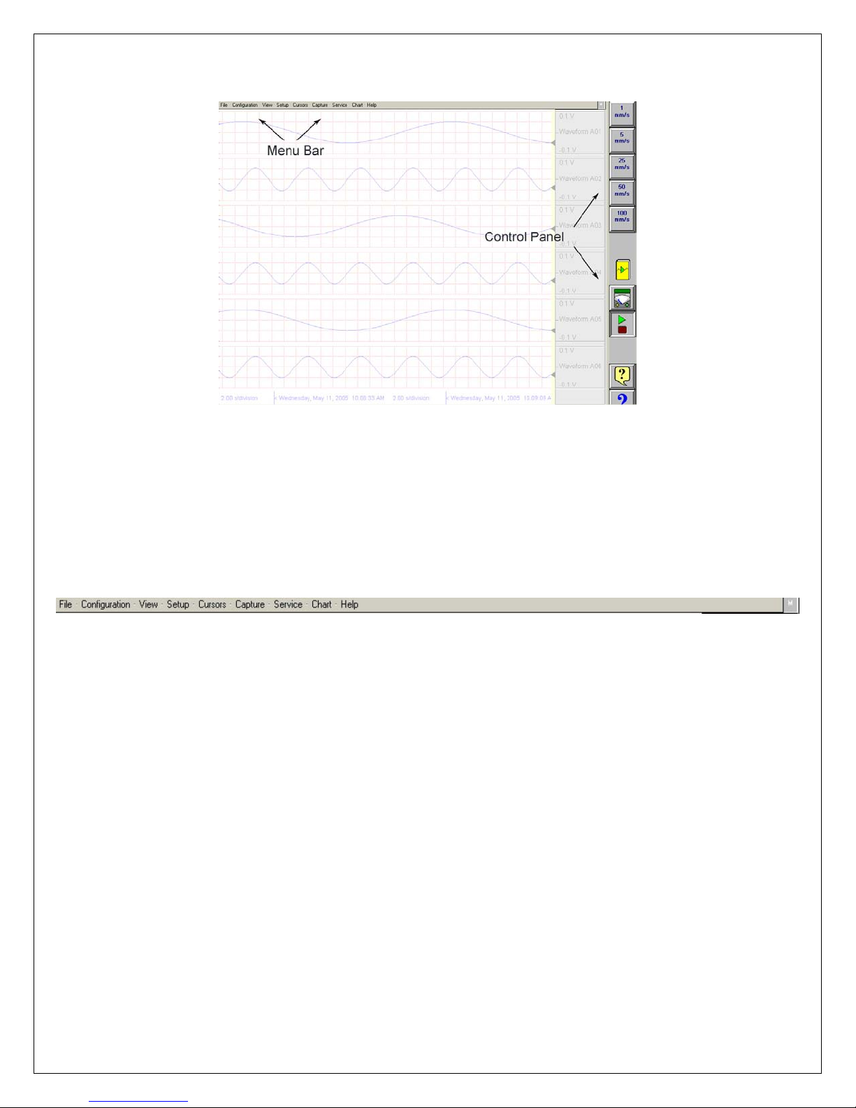
Display: The Dash 8Xe / Dash 8X has a large touchscreen display. The display is divided into two main areas, the
Waveform Display Area (shows the waveform signals typically drawn onto a grid pattern) and the Control Panel (rows of
control icons for operation).
33.. HHAARRDDWWAARREE OOVVEERRVVIIEEWW
The following is a summary of the location of the physical components of the Dash 8Xe / Dash 8X.
Front View:
Touch Screen, Carry Handle
Right Side View:
Left Side View:
Signal Modules (up to eight signal modules), Computer connections (parallel port, serial port,
USB port, Ethernet port, Mouse port, Keyboard port, VGA port)
Power indicator light, Power switch, Power inlet, Scope card (optional), Utility port, Recorder
port (model SCR-8), Link ports, Event port, DC Input
2
Page 3
44.. MMEENNUUSS && IICCOONNS
S
Dash 8Xe / Dash 8X screen highlighting the Menu Bar and Control Panel
MENU BAR
File The File menu is used to save and load your setup files.
Configuration The Configuration menu is used to select the operation of the Dash 8Xe / Dash 8X.
View The View menu is used to supplement the graph display of your signals.
Setup The Setup menu is used to configure the Dash 8Xe / Dash 8X.
Cursors The Cursors menu is used for time and amplitude measurements.
Capture The Capture menu is used to setup, arm, manual trigger, and abort data captures.
Service The Service menu is for less frequently used parameters such as calibration and security settings.
Chart The Chart menu provides for operation of the optional SCR-8 thermal recorder.
Help The Help menu provides for on-line assistance.
CONTROL PANEL
The menu bar is a group of drop-down menus located across the top of the display.
All Dash 8Xe / Dash 8X modes and features can be accessed from this menu. Options
available from the menu bar will vary based on the mode of operation (Realtime, Scope, or
Review) used.
If the date and time are visible instead of the menu bar, choose the M icon in the upper right
hand corner, which toggles the display of date/time and menu bar.
The control panel is an array of icon-based icons located on the right hand side of the display.
The icon icons allow for a single touch to execute a function. The Dash 8Xe / Dash 8X ships
with the control panel displaying icon icons for speed control, analog set up, meter mode, and
run/halt.
The control panel can be customized to add or remove icon icons to suit your recording
needs. Further, the control panel settings can be saved to a file for later recall making test
preparation very easy.
3
Page 4
Commonly Used Icons
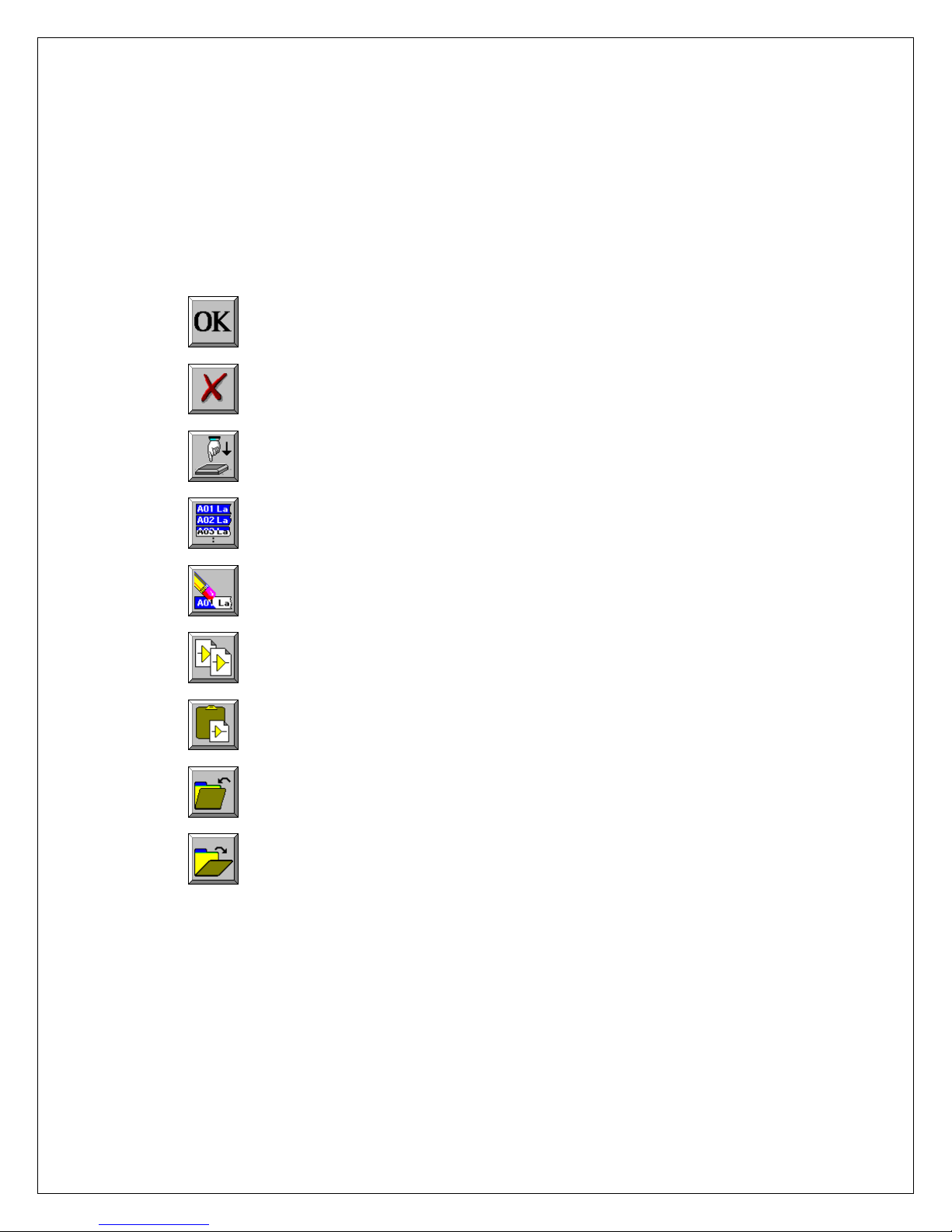
The following icons are commonly used in Dash 8Xe / Dash 8X windows:
OK saves the information you entered in a window and then closes the window.
Exit cancels the action you were performing in a window and
closes the window without saving any changes.
Apply saves the information you modified in a window without closing the window.
Select All selects/highlights all items in a list box.
Clear Selection removes the selections/highlights from all items in a list box.
Copy copies the selected items (or characteristics of sele cted items) to the clipboard.
Paste pastes the clipboard contents to the selected location.
Save saves current configurations to a file on your disk.
Load loads configurations from a file on your disk.
4
Page 5
55.. UUSSIINNGG TTHHEE DDaasshh 88XXee // DDaasshh 88XX
The Dash 8Xe / Dash 8X has three modes of operation, Realtime, Scope, and Review modes.
Realtime Mode: Realtime mode provides real-time waveform scrolling, monitoring, and data capture capabilities.
Additionally, almost all system setup options are accessible from Realtime mode.
Scope Mode: Scope mode acts like a digital storage oscilloscope, providing high time-base resolution for viewing hig h-
frequency signals. If the optional DSO-8 scope card is installed, high-speed scope captures up to five million samples per
second can be acquired using Card mode.
Review Mode: Review mode provides the capability to review and analyze saved data captures and scope captures.
Help: Within the Dash 8Xe / Dash 8X, three forms of help are available:
Context Help
Icon Help
Online Manual
The context help feature provides context sensitive, on-screen
help.
The icon help feature provides on-screen help for the icons.
A brief description is of the selected icon is provided.
The Adobe Portable Document Format (PDF) version of the
manual is available in the Dash 8Xe / Dash 8X for on-screen
viewing. This softcopy manual can be viewed on the Dash 8Xe /
Dash 8X from Scope, Realtime or Review mode by selecting
Help>>On-Line Help from the drop-down menu.
6.6. SETTING UP THE DISPLAY APPEARANCE
The Dash 8Xe / Dash 8X gives you total control over chart layout. You can set individual channel widths, channel
location, grids ON/OFF, and major/minor division sizing. You are also able to suppress or enable waveform display as
well as vary the waveform trace thickness. Further, you can overlap some or all of the channels.
Basic Channel Views: The Dash 8Xe / Dash 8X provides basic channel views that you can access from the menu bar.
These views allow you to choose a fixed number of channels to display. In Realtime mode, choices are Basic 2, 4, or All
channels. In Scope or Review mode, choose from 1, 2, 4, or All channels.
Custom Channel Views: If you don’t find a view from the Basic Channel Views described above, you can use the
Chart / Display wizard. The wizard allows you to pick the number of channels to display. You can further customize your
chart by overlapping or resizing the channels. You can also add, remove, or replace channels.
77.. AAMMPPLLIIFFIIEERR SSEETTTTIINNGGSS
For each channel of the Dash 8Xe / Dash 8X, a unique signal input module is installed in the right side of the recorder
(example: IHV1). Each channel has unique amplifier settings. It addition to setting the span for the channel, you can also
adjust the zero volt position. For convenience, amplifier settings can be copied to other channels, when the channels
share the same type of signal input module. Further, user scaling is supported so that your channels can report their
values to you in Engineering Units.
SETTING UP THE DISPLAY APPEARANCE
5
Page 6
88.. SSAAMMPPLLEE EEXXEERRCCIISSEES
9 Volt Battery Test
Items needed: 9 Volt battery. Signal input leads.
In the following hands-on exercise, you will set up a channel to monitor a 9 Volt battery in Realtime. Next, a data capture
will be set up to record when the battery voltage is applied. Finally, the captured data will be reviewed.
Note: The steps below are for the NDV1 or IHV1 voltage modules installed in Slot 1 (Channel 1).
Please contact Astro-Med if you have any questions regarding the use of other modules.
In the exercise, every action needed is detailed in a step-by-step fashion to help you quickly become familiar with the
operation of the Dash 8Xe / Dash 8X. The ACTION on the left-hand side describes what is to be done.
The HOW TO section provides the detailed steps to take using the pull-down menus of the Menu Bar.
S
I. Real-time Monitoring: Monitor the voltage of a 9 Volt battery.
Set up the channel so that when there is no signal, the waveform trace will be at the center of the channel and when the 9
Volt signal is applied, the waveform trace will be near the top of the channel.
ACTION HOW TO (Use the Menu Bar Pull-Down menus)
Verify Menu Bar display
Default the
Dash 8Xe / Dash 8X
Enter Realtime Mode
View All Channels
Set speed to 5 mm/sec
If the date and time are shown at the top of the screen, press the M icon in
the upper right hand corner to show the Menu Bar.
Dash 8Xe / Dash 8X Menu Bar
Choose Configuration >> Utilities from the menu bar to open the Utilities
window.
Choose Defaults >> System from the menu bar to set the recorder to
factory defaults.
Click Yes to accept.
Choose Configuration >> Realtime from the menu bar to enter Realtime
Mode.
Choose View >> Basic All Channels from the menu bar.
Press the [5 mm/s] icon on the control panel.
Continued…
6
Page 7
Set Channel #1 to be
20 Volts Full Scale
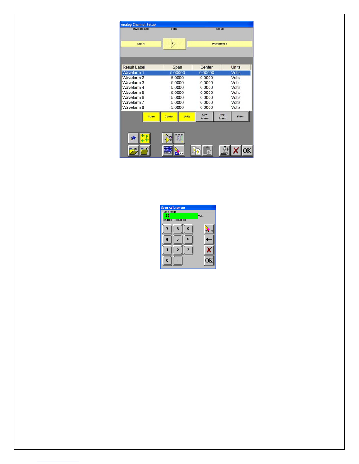
Dash 8Xe / Dash 8X Amplifier Channel Settings Window
Choose Setup >> Amplifier Channel Settings from the menu bar.
Highlight Waveform 1.
Span adjustment keypad
Press the Span column. Press the digit “2” and “0” to select twenty. Press
OK.
Input battery voltage into
Channel #1
Measure the battery
voltage using the color
display
Use the banana jack input connection located on the side of
the Dash 8Xe / Dash 8X and input the battery voltage into Channel #1.
Choose View >> Meter from the menu bar to activate the Meter Mode.
Observe the battery voltage.
Choose View >> Meter from the menu bar to remove the meter.
Remove battery voltage.
This completes the first part of the exercise, Realtime Monitoring.
7
Page 8
II. Data Capture Settings:
Set up a single data capture for 10 seconds. Of the total capture time, two seconds of the capture should show what the
signal looked like before the battery voltage was applied. The sample rate will be 1,000 samples per second.
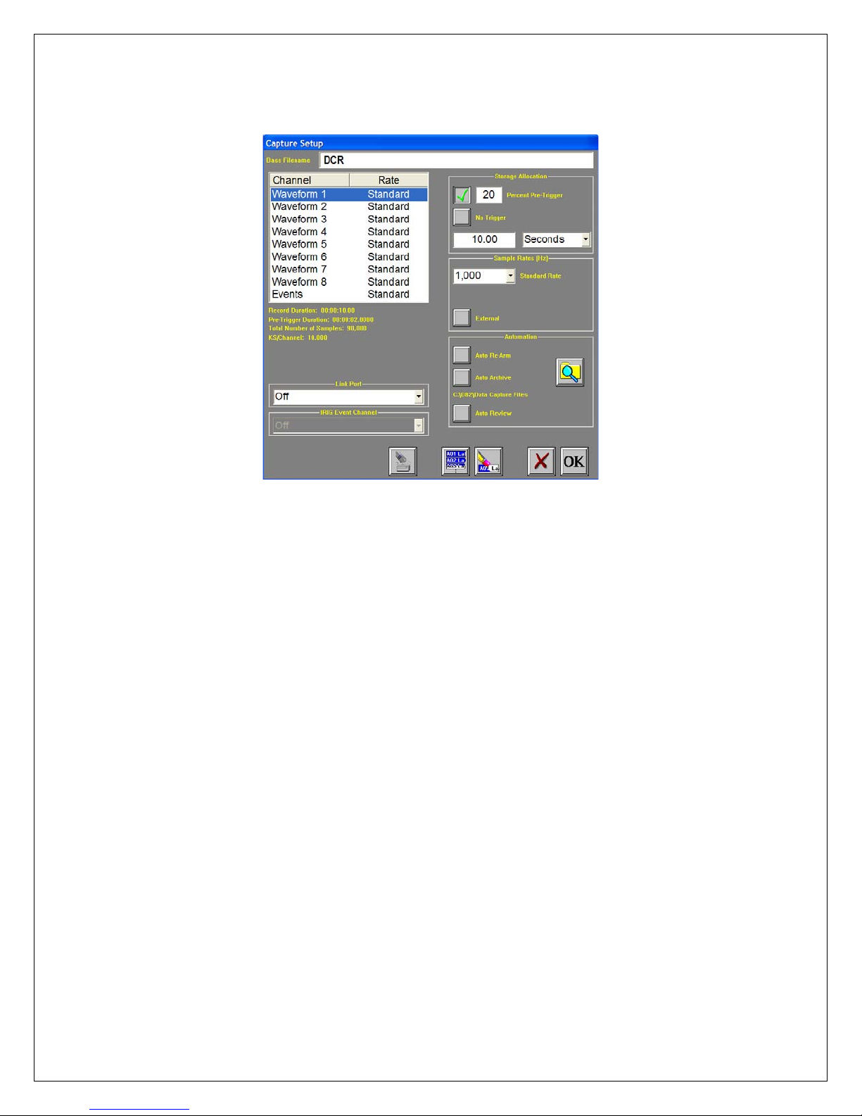
Capture Settings Window
ACTION
Enter data capture setup
Select capture of
Channel 1
Set sample rate to 1 kHz
HOW TO (Use the Menu Bar Pull-Down menus)
Choose Capture >> Capture Settings from the menu bar for data capture
setup.
Highlight Waveform 1. Be sure the Rate for Channel 1 is Standard. If not,
click on the Rate menu bar and select Standard.
In the Sample Rates box, press the down arrow titled Standard Rate.
Scroll down and press 1,000.
Set capture for 10
seconds
In the Storage Allocation box, press the units pull-down box and select
Seconds. (Other choices are minutes, hours and Ksamples).
Press the value box to open the Seconds Window.
Press the digits “1” and “0”. Press OK.
Set trigger point at 20%
In the Storage Allocation box, press the Percent Pre-trigger box. Press the
digits “2” and “0”. Press OK. Be sure there is a green check mark next to
the Percent Pre-Trigger.
Verify time of capture
Below the waveform selection window, in yellow text, the Record Duration
should be 10 seconds, the Pre-Trigger Duration should be 2 seconds.
Set capture for one
record
In the Automation Box, be sure that both the Auto Re-Arm & Auto Archive
are not checked. At this point, your Capture Settings Window should look
like the image above.
Save and exit data
capture setup
Press OK.
This completes the second part of the exercise, Data Capture Settings.
8
Page 9
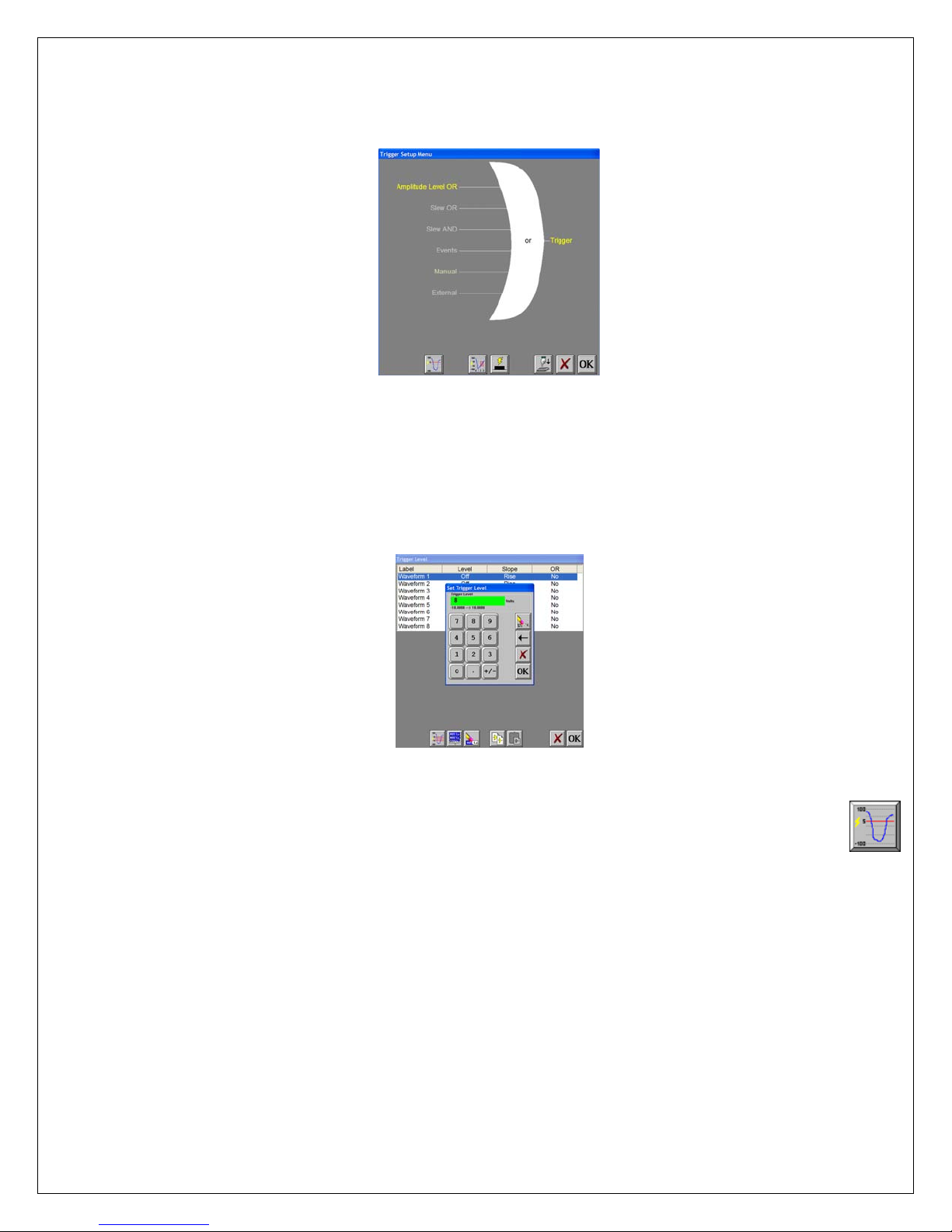
III. Trigger Setup and Data Capture:
In the Data Capture Settings section above, a ten second capture was set up with two seconds of pre-trigger (data before
the trigger). In this section, a trigger level of 8 Volts will be set with a rising slope so that as the signal rises and reaches 8
Volts, the data capture will be triggered.
Trigger Settings Menu
ACTION HOW TO (Use the Menu Bar Pull-Down menus)
Enter Trigger Settings
Select level triggering
Choose Setup >> Trigger Settings from the menu bar to enter Trigger Settings.
Press Amplitude Level OR to highlight in yellow. Be sure all other trigger types (other OR
types, AND types, manual, etc. ) are not highlighted. If so, press them to deselect.
Trigger Level
Set to trigger when 9
Volts is applied
Press the Trigger Level icon (1
Trigger Level window, highlight Waveform 1.
ST
icon in the row of icons at the bottom). In the
Press Level. Then press New Value. Press the digit “8”. Press OK.
Press Slope. Then press Rise. Press OR. Then press Yes.
Press OK at the lower right hand corner of the menu.
You have just set the trigger to be asserted when the signal input into
channel one rises past 8 Volts.
Save/exit trigger setup
Press OK. Press OK.
Arm for capture
Choose Capture >> Arm from the menu bar to arm for capture.
The Capture Progress window pops up indicating status.
Input battery voltage into
Channel #1
A trigger should be produced and the capture continues to the end.
While capturing, you should have seen the waveform for Cha nnel #1
increase from the bottom of the channel to near the top of its channel.
This completes the third part of the exercise, Trigger Setup and Data Capture.
9
Page 10
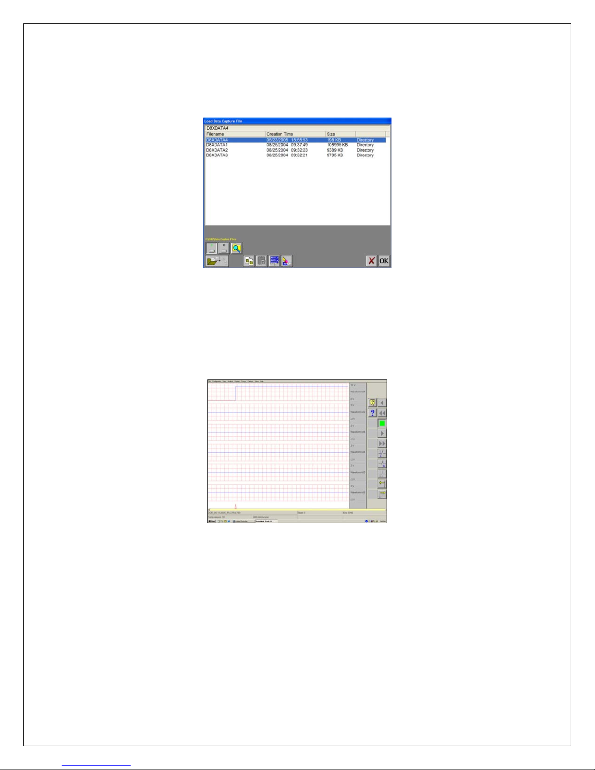
IV. Data Review:
Data capture records can be reviewed on the color display. DVD-like control icons allow for convenient scrolling through
the data. Cursors can be placed on the data for measurements. During review, the timebase can be expanded or
compressed to give appropriate detail of the signal. From the display, part of or all the data can be saved.
List of data capture records for review
ACTION HOW TO (Use the Menu Bar Pull-Down menus)
Enter Review Mode
Select file to be reviewed
Show entire capture
Show the trigger point
Choose Configuration >> Review from the menu bar to enter the Review
Mode.
Click on the top-most file name to highlight the capture. Press OK.
Data Capture Review of 9 Volt battery data capture
Choose Display >> Show All File from the menu bar to show entire capture.
Note: If the entire file is already shown, a check mark will be next to Show All File in the
Display pull-down menu.
Choose Display >> Show Trigger Line from the menu bar to show the trigger point.
Note: The trigger line is shown as a red vertical line. If the trigger line is already shown, a
check mark will be next to Show Trigger Line in the Display pull-down menu. Be sure the
trigger line is shown on the display.
Continued…
10
Page 11
Show only Channel 1
Expand the time base
Scroll through the data
Cursors
Time measurements
using cursors
Amplitude
measurements
using cursors
Remove the cursors
Show entire capture
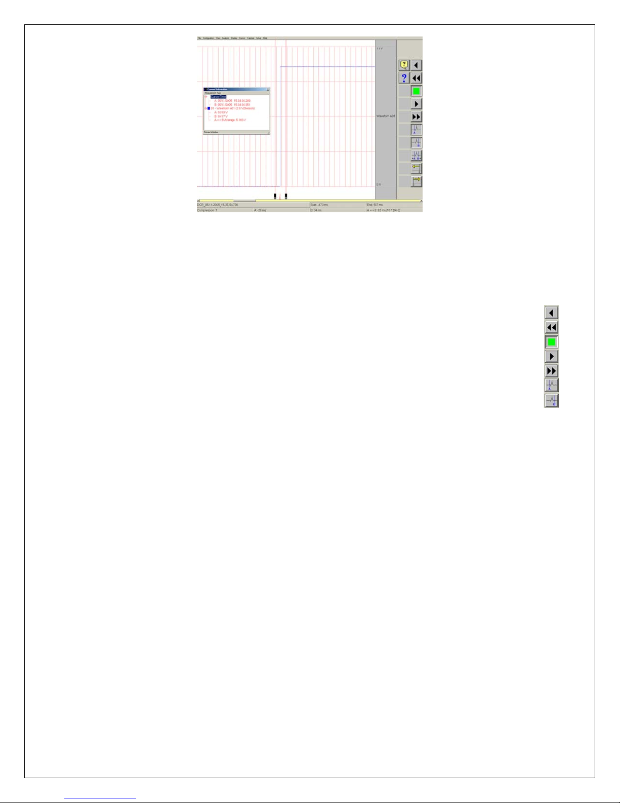
Using cursors to make measurements
Choose View >> 1 Channel from the menu bar to show only Channel 1.
Choose Display >> Compression from the menu bar. Press the digit “1”.
Press OK.
Use DVD icons. You can jog forward or backwards through the data. You
can stop at any points of interest. Experiment scrolling forwards and
backwards.
Continue to scroll and stop the display when you have the trigger point (red
vertical line) in the middle of the display.
Press the A cursor icon. Slide the cursor just to the left of the trigger point.
Press the B cursor icon. Slide the cursor just to the right of the trigger point.
Choose View >> Status Text Format >> Relative Time from the menu
bar. Observe the time values shown at the bottom.
Choose View >> Show Channel Information from the menu bar.
Move Cursor B by sliding it to the right. As you move the cursor, observe
the change in values in the Channel Information window.
Press the A cursor icon and B cursor icon to remove them.
Choose Display >> Show All File from the menu bar to show entire
capture.
This completes the sample exercise.
11
Page 12
99.. AARRCCHHIIVVIINNGG DDAATTAA RREECCOORRDDSS
There are two hard drives in the Dash 8Xe / Dash 8X. The first is the Windows (System) drive and the second is the data
capture drive. During data capture, the data is streamed to the data capture drive. Once the data capture is complete, the
file can be reviewed on the Dash 8Xe / Dash 8X. However, to export the data out of the Dash 8Xe / Dash 8X, the user
must archive it from the data capture drive to the Windows (system) drive or directly to an external USB source.
The data capture drive is not accessible through Windows Explorer. The only way to export or archive the data off the
capture drive is by using the Dash 8Xe / Dash 8X software environment. Data is handled this way in order to maintain the
integrity of the recording.
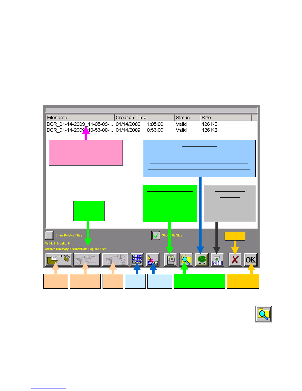
ACTION HOW TO (Use the Menu Bar Pull-Down menus)
Enter Review Mode
Choose Configuration >> Review from the menu bar to enter Review Mode.
Send file
to trash
Choose Archive
Directory
Files on data capture drive
not Windows (system) driv e.
Select to review or archive.
Selected file will be highlighted.
Selected
archive
destination.
Restore file
from trash
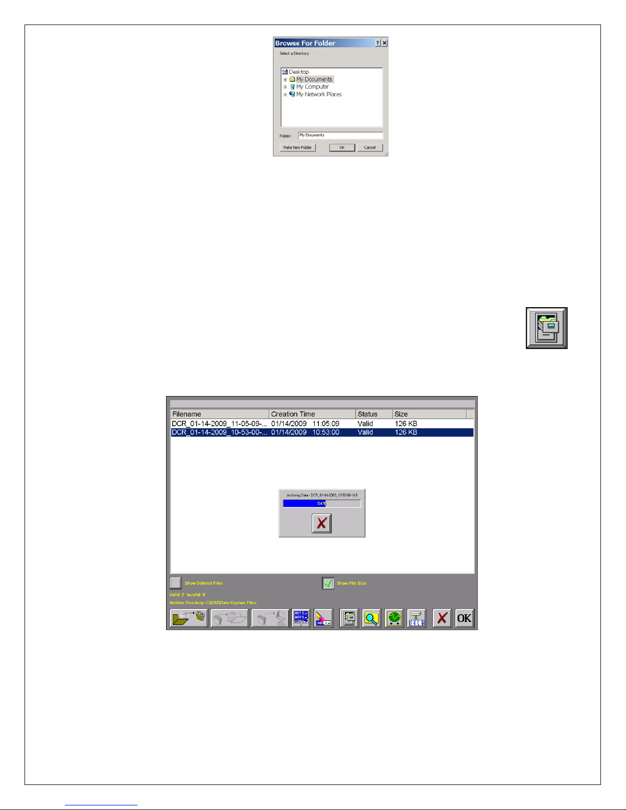
By default, the file will be saved on the system drive (C) in the noted
location. The path to this location is displayed in yellow text (see
above). If necessary, the file can be saved in a different location. To
select an alternative file location, the Browse/select archive folder icon.
Empty
trash
Summary of Review Mode Screen Icons
The Browse for Folder window will appear.
Select
all files
Scope Captures:
Lists scope capture files on Windows (system),
or external drive
Note: Scope captures are stored directly to the
Windows (system) drive. Think of these items as
“automatically archived.”
Archive Selected File:
Archives selected data
capture file/files to
selected Windows
(system), or
external drive.
Deselect
file/files
Browse/select
archive destination.
Archived Data
Captures:
Lists archived data
capture files on
Windows (system),
or external drive.
Cancel
Open
selected File
Browse/select
archive folder Icon
Continued…
12
Page 13
Select File Location
Select File to Archive
Archive File
Browse for Folder window
Note: The Dash 8Xe / Dash 8X, USB port is assigned drive letter D.
Select a file location and choose the OK icon on the Browse for Folder
window. The path displayed in yellow text will be updated to indicate the
new file destination.
Select the file that you wish to archive. The selected file will be
highlighted.
Select the Archive File icon to archive the selected file.
A status pop-up will appear showing the percentage completed.
Once the file has completed archiving, select OK to exit the Review
mode screen.
Archive Selected
File/Files Icon
Review Mode Screen Showing Archiving file Status
Note: The Dash 8Xe / Dash 8X series offers additional methods to archive data.
The user can archive all or part of a file while reviewing along with archiving in ASCII format.
Please see the Dash 8Xe / Dash 8X operations manual for additional information.
This concludes the Archiving Data Records section.
13
Page 14
1100.. EENNTTEERRIINNGG EENNGGIINNEEEERRIINNGG UUNNIITTSS
Engineering units provide the capability to display user-selected units instead of voltage. All signal information enters the
Dash 8Xe / Dash 8X as voltage. However, converting the voltage unit to an alternative unit of measure may be desirable
in applications that measure current, pressure, strain, or any non-voltage unit.
This allows the Dash 8Xe / Dash 8X to be compatible with transducers and probes that can provide a voltage output to
the Dash 8Xe / Dash 8X. The relationship between the voltage and the engineering unit is assumed to be linear,
characterized by a slope and offset (y = mx + b).
The following is an example of entering engineering units into the Dash 8Xe / Dash 8X. For this example, we will assume
we are entering the engineering units for a current probe that provides a 10mV/A voltage output to the Dash 8Xe / Dash
8X.
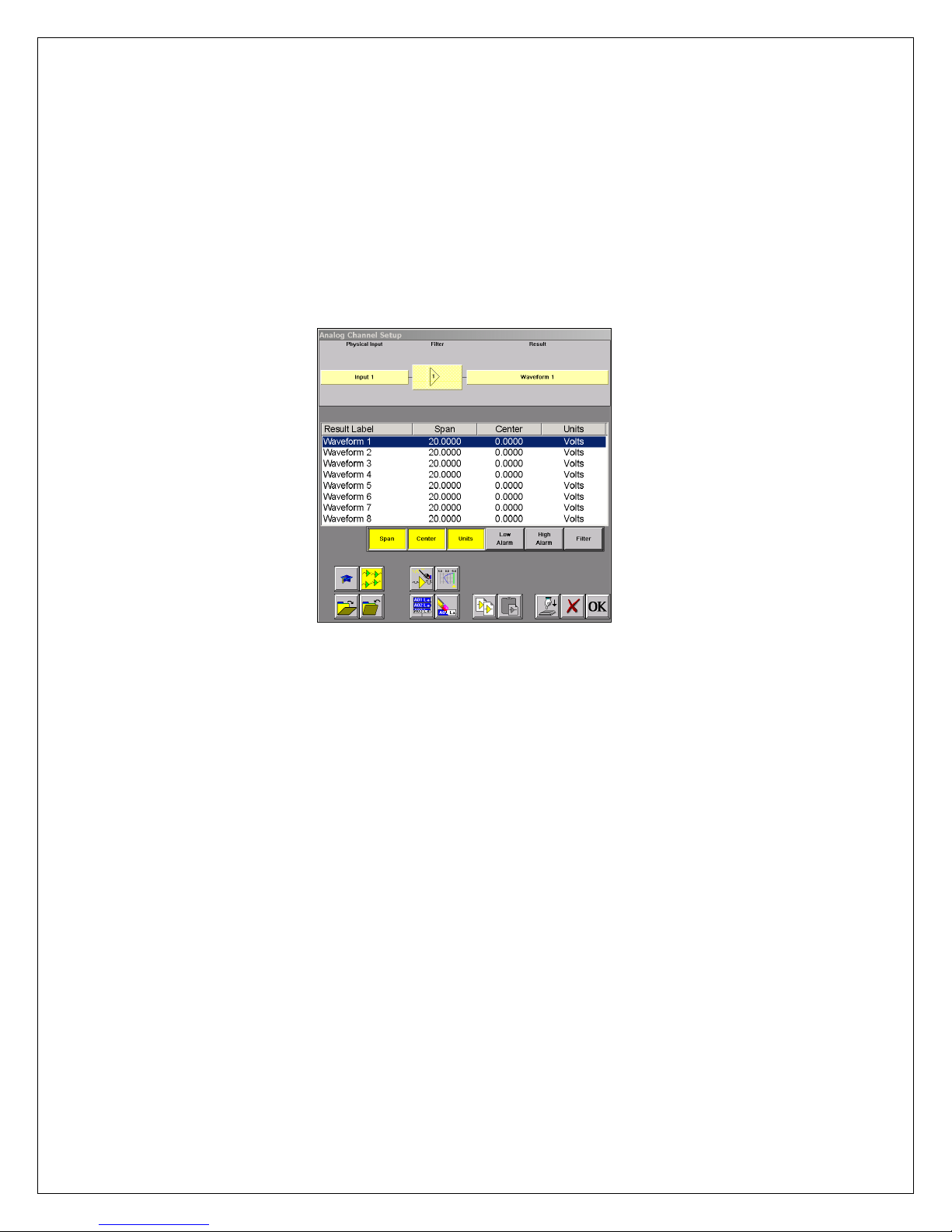
Dash 8Xe / Dash 8X Amplifier Channel Settings (Analog Channel Setup) Window
ACTION HOW TO (Use the Menu Bar Pull-Down menus)
Set the engineering
units on Channel #1 to
be 10mV/A
Open User Units Menu
Enable User Units
Enter User Unit
Choose Setup >> Amplifier Channel Settings (Analog Channel Setup) from the menu bar.
The Amplifier Channel Settings (Analog Channel Setup) menu will appear.
Highlight Waveform 1.
On the Amplifier Channel Settings (Analog Channel Setup)
window, Choose Units >> Enter User Units, the User Unit Setup –
Waveform 1 window will appear.
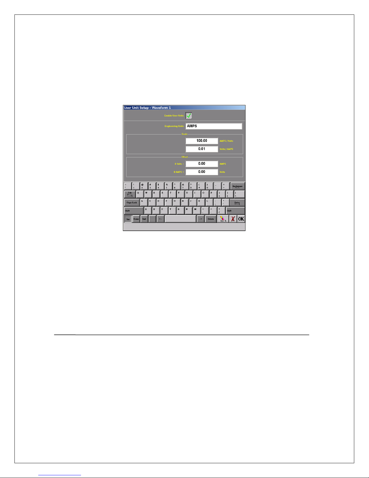
Select the Enable User Units icon located in the top center of the
User Unit Setup – Waveform 1 window. The Enable User Units
icon should be checked.
Select the Engineering Units box under the Enable User Units
icon. A keypad will appear. Erase the unit Volts and enter AMPS.
Continued…
14
Page 15
Enter Scale
Under the Engineering Units box on the User Unit Setup – Waveform 1 window there is a
section named Scale. Now that you have entered AMPS, you can now enter either
AMPS/Volts or Volts/AMPS.
Since our probe has a 10mV/A output, we will enter 0.01 into the Volts / AMPS box.
Press the Volts / AMPS box and enter 0.01 into the Scale keypad.
Press OK on the Scale keypad.
Press OK on the User Unit Setup – Waveform 1 screen.
Press OK on the Amplifier Channel Settings (Analog Channel Setup) window.
Waveform (Channel) 1 is now set to measure current using a 10mV/A current probe.
User Unit Setup – Waveform 1
This concludes the engineering units example.
1111.. PPOOWWEERRIINNGG DDOOWWNN
When the power switch is set to the off position or if AC power is lost or removed, the Dash 8Xe / Dash 8X begins the
power down sequence. This is indicated by the green LED next to the power switch that will be on while the power down
sequence occurs. Note that the LED will either be a solid green or it may flicker. It is very important not to turn the power
switch back to the on position during the power down stage. The Dash 8Xe / Dash 8X must be allowed to complete the
power down sequence to insure proper operation.
This completes the Dash 8Xe / Dash 8X Quick Start Guide. Please note that the Dash 8Xe / Dash 8X has much more
capability than presented in this guide. Please see the Operations Manual for details. Should you require additional
assistance, you can contact our Technical Support Department toll-free at 877-867-9783 or b y e-mail:
15
 Loading...