

Page 1
ASTRO MACHINE CORP.
630 Lively Blvd.
Elk Grove Village, IL 60007
Phone: (847) 364-6363
Fax: (847) 364-9898
www.astromachine.com
TM
AstroJet
M1
COLOR PAGE
PRINTER
OPERATOR MANUAL
Page 2

SAFETY PRECAUTIONS
THIS EQUIPMENT PRESENTS NO PROBLEM WHEN USED PROPERLY.
HOWEVER, CERTAIN SAFETY RULES SHOULD BE OBSERVED WHEN
OPERATING THE ASTROJET M1 PRINTER.
BEFORE USING THE PRINTER, YOU SHOULD READ THIS MANUAL
CAREFULLY AND FOLLOW THE RECOMMENDED PROCEDURES, SAFETY
WARNINGS, AND INSTRUCTIONS:
Keep hands, hair, and clothing clear of rollers and other moving parts.
Avoid touching moving parts or materials while the machine is in use. Before clearing a jam, be
sure machine mechanisms come to a stop.
Always turn off the machine before making adjustments, cleaning the machine, or performing
any maintenance covered in this manual.
The power cord and power supply supplied with the machine should be plugged into a properly
grounded, easily accessible wall outlet near the machine. Failure to properly ground the
machine can result in severe personal injury and/or fire.
The power cord and wall plug is the primary means of disconnecting the machine from the
power supply.
DO NOT use an adapter plug on the line cord or wall outlet.
DO NOT remove the ground pin from the line cord.
DO NOT route the power cord over sharp edges or trap it between furniture.
Avoid using wall outlets that are controlled by wall switches or shared with other equipment.
Make sure there is no strain on the power cord caused by jamming it between equipment, walls
or furniture.
DO NOT remove covers. Covers enclose hazardous parts that should only be accessed by a
qualified service representative. Report any cover damage to your service representative.
This machine requires periodic maintenance. Contact your authorized service representative for
required service schedules.
To prevent overheating, do not cover the vent openings.
Use this equipment only for its intended purpose.
In addition, follow any specific occupational safety and health standards for your workplace or area.
This manual is intended solely for the use and information of Astro Machine Corp., its designated
agents, customers, and their employees. The information in this guide was obtained from several
different sources that are deemed reliable by all industry standards. To the best of our
knowledge, that information is accurate in all respects. However, neither Astro Machine Corp. nor
any of its agents or employees shall be responsible for any inaccuracies contained herein.
AstroJetTM is a registered trademark of Astro Machine Corp.
Memjet® is a registered trademark.
All other trademarks are the property of their respective holders.
All rights reserved. No part of this book may be reproduced or transmitted in any form or by any means, electronic or mechanical,
including photocopying, recording, or any information storage and retrieval system, without permission in writing from the publisher
Page 3

TABLE OF CONTENTS
SECTION 1 – Getting Acquainted 1
Front View 1
Rear View 2
Print Engine View 3
Ink Tank Door View 4
Control Panel Button/LED Indicators 5
SECTION 2 – Installing the Printer 6
Contents of Packaging 6
Choose a Location 6
Unpacking and Setup 6
Remove Service Station Transport Tab and Shipping Tape 7
Assembling the Printer 8
Connecting the Printer 9
Connecting to the Computer 9
Install the Printer Driver 10
Install the Ink Tanks 12
Install the Printhead Cartridge 14
Removing the Head Media Guide 17
Install/Remove Envelope Attachment Spacers 18
Setting up the Feed 19
SECTION 3 – Operating the M1 Printer 21
Setting Up a Job in MS Word 21
Printer Driver Properties 23
General Tab 23
Layout Tab 24
Import/Export Tab 26
Services Tab 26
Using the Printer Toolbox 27
Updating Firmware 33
SECTION 4 – Maintenance 34
Replacing the Ink Tanks 34
Cleaning Ink Tank Contacts 35
Cleaning/Replacing the Printhead Cartridge 37
Replacing the Service Station 43
Replacing the Ink Waste Tray 47
Replacing the Sheet Separators 47
Jams in the Printer 48
Cleaning 49
Shipping or Transporting the Printer 51
SECTION 5 – Troubleshooting Guide 54
The Memjet® Printhead 54
The Printer 55
Errors and Warnings 56
Appendices 61
Appendix A – AstroJet M1 Specifications 61
Appendix B – Supplies and Optional Hardware 61
Index 62
Printer Maintenance Schedule 65
Control Panel LED Sequences 67
i
Page 4

TABLE OF CONTENTS
NOTES
______________________________________________________
______________________________________________________
______________________________________________________
______________________________________________________
______________________________________________________
______________________________________________________
______________________________________________________
______________________________________________________
______________________________________________________
______________________________________________________
______________________________________________________
______________________________________________________
______________________________________________________
______________________________________________________
ii
Page 5
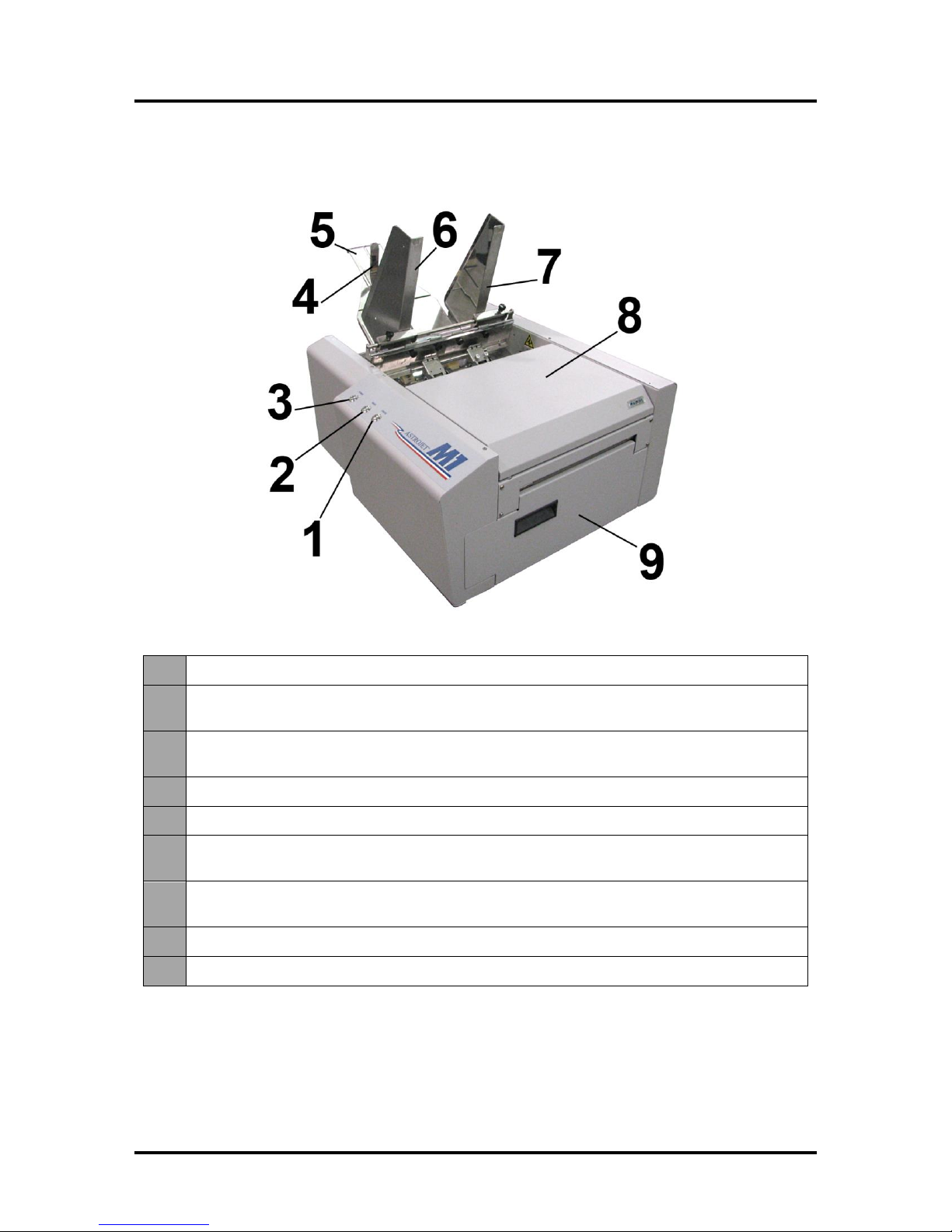
1.
Cancel LED Button – Cancels the job being printed.
2.
Paper LED Button – Press to stop printing, press to restart printing. Press switch to
continue printing.
3.
ON/OFF LED Button – Use to turn power ON or OFF during idle time and
maintenance.
4.
Rear Guide – Holds the media against the Front Plate.
5.
Rear Guide Support – Supports the paper/media.
6.
Adjustable Media Guide – Adjusts to hold the paper/media against the
Envelope/Paper Register Guide.
7.
Envelope/Paper Media Guide – All printing is registered against this Guide. It has
adjustable positions for envelopes and paper.
8.
Top Cover – Provides access to the Print Engine.
9.
Front Cover – Provides access to the Service Station and Ink Tanks.
SECTION 1 – Getting Acquainted
SECTION 1
GETTING ACQUAINTED
Front View
1
Page 6
SECTION 1
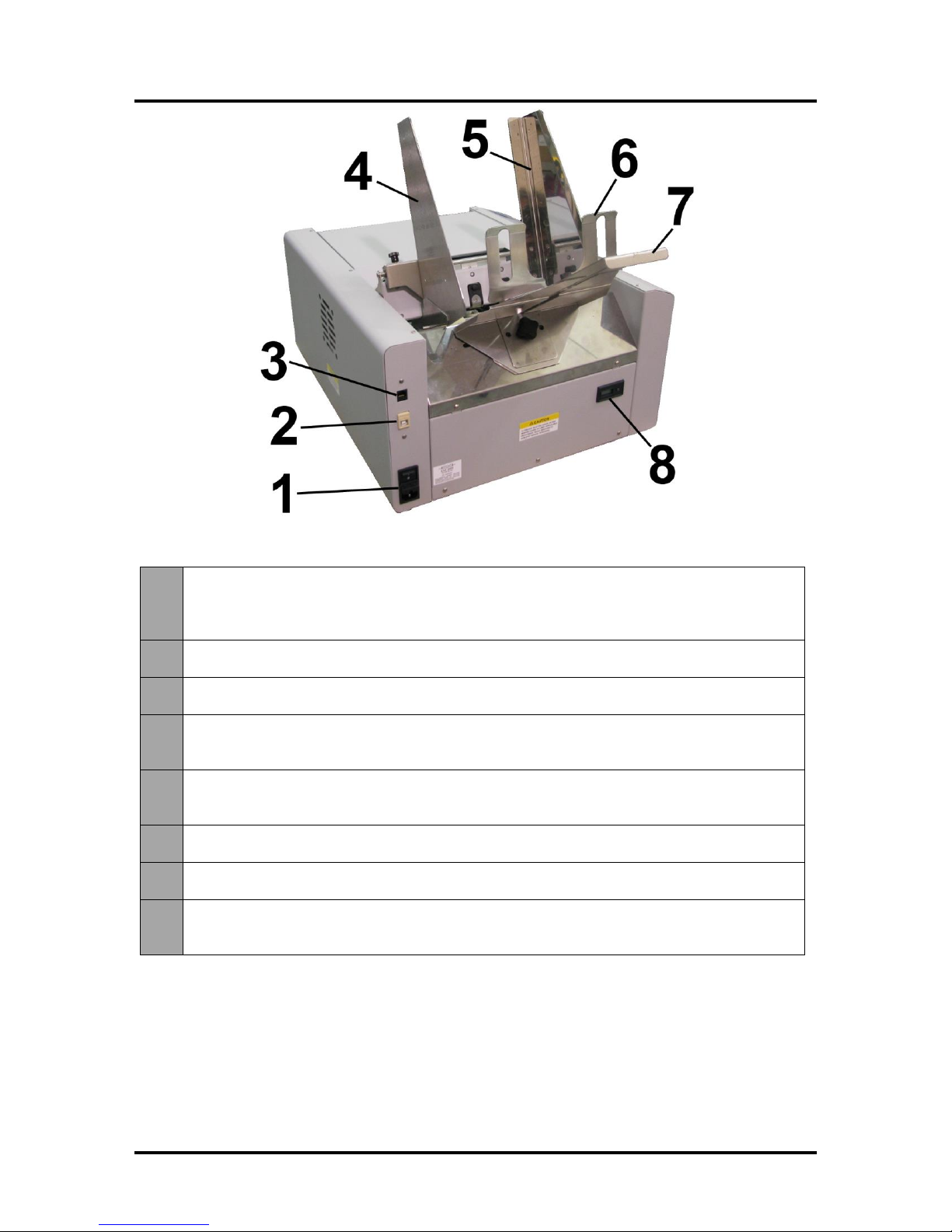
1.
Main Power Switch, Receptacle and Fuse – Plug in power cord here. Switch turns
main power ON/OFF. (Use the Control Panel LED Power switch to turn off machine for
cleaning and maintenance). Fuse protects the Printer’s electronic circuits.
2.
USB Port Connection – The USB cable attaches to the Printer here.
3.
Network Connection – The network cable plugs in here.
4.
Envelope/Paper Media Guide – All printing is registered against this Guide. It has
adjustable positions for envelopes and paper.
5.
Adjustable Media Guide – Adjusts to hold the paper/media against the
Envelope/Paper Media Guide.
6.
Rear Guide – Holds the paper/media against the Front Plate.
7.
Rear Guide Support – Supports the paper/media.
8.
Counter – LCD displays number of pieces run for a given job. The Reset button zeros
the Counter.
GETTING ACQUAINTED
Rear View
2
Page 7
SECTION 1
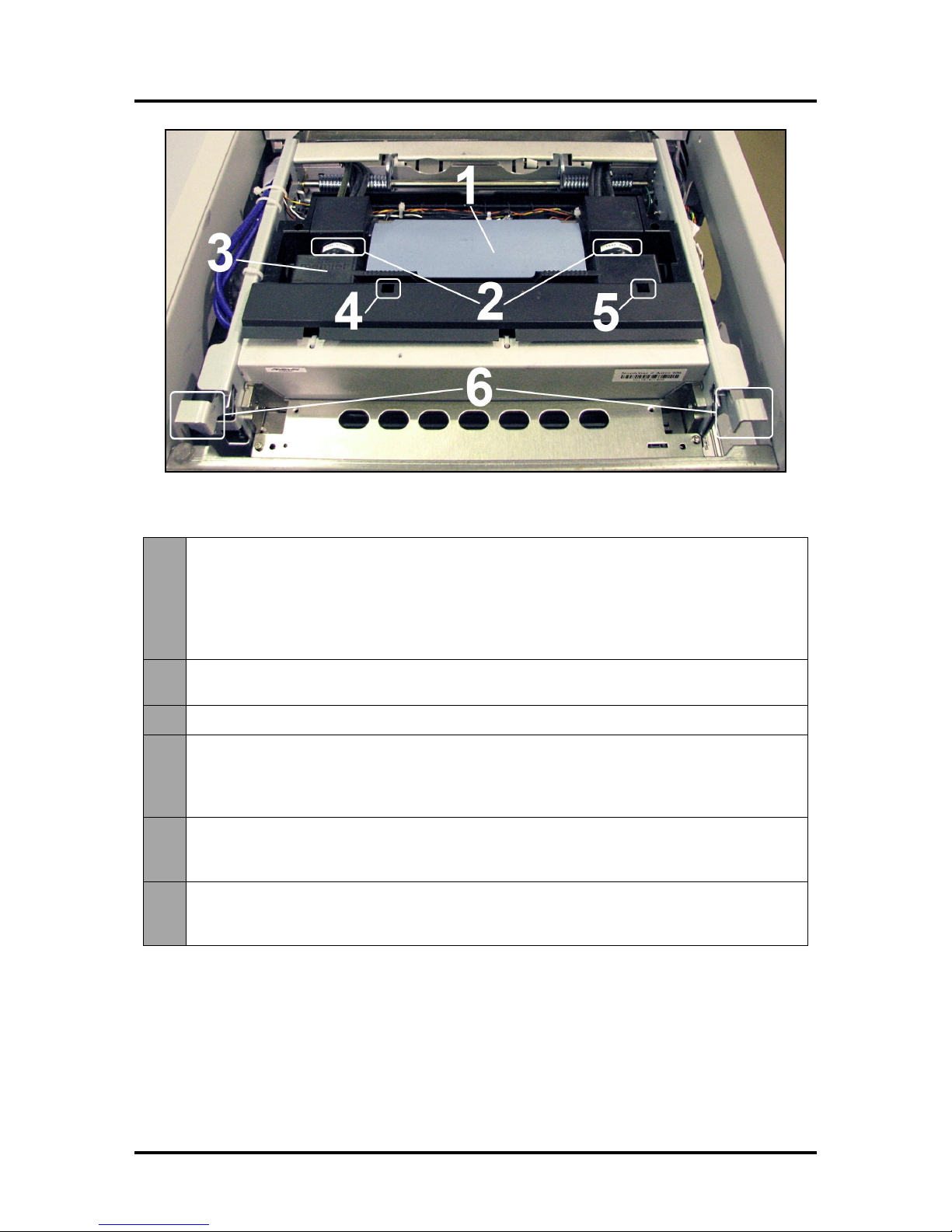
1.
Printhead Latch – When closed, connects the Ink Revolver Couplings with the
Printhead Cartridge. When opened, retracts the Ink Couplings from the Printhead
Cartridge and provides access to the Printhead Cartridge for cleaning and replacement.
WARNING! Never attempt to open the Printhead Latch manually, severe damage will
result. Use the Printhead Release button function in the Toolbox utility on your PC or
press the Printhead Latch Release Button (See #4 below).
2.
Ink Revolver Couplings – Connect the ink hoses to the Printhead Cartridge. The
Printhead Latch extends and retracts the couplings from the Printhead.
3.
Printhead Cartridge – Memjet® Printhead produces an 8.5" wide full color print area.
4.
Printhead Latch Release Button* – Button inside opening will initiate a Printhead
Latch release cycle. If system is primed, runs a full system deprime cycle before the
Latch is released. Lightly press the button with a non-conductive tool.
*Same function can be accessed through the Printer Toolbox User Interface screen on your computer.
5.
Print Ink Channels Button* – Prints 5 bars (1 bar from each ink tank) to indicate how
well the Printhead Nozzles are working. Press the button with a non-conductive tool.
*Same function can be accessed through the Printer Toolbox Diagnostics screen on your computer.
6.
Clamshell Latches – Lift both latches at the same time to open the top half of the Print
Engine. DO NOT open while the Printer is operating. DO NOT lift the Clamshell more
than 60 degrees. DO NOT let the Clamshell drop, close it gently.
GETTING ACQUAINTED
Print Engine View
3
Page 8
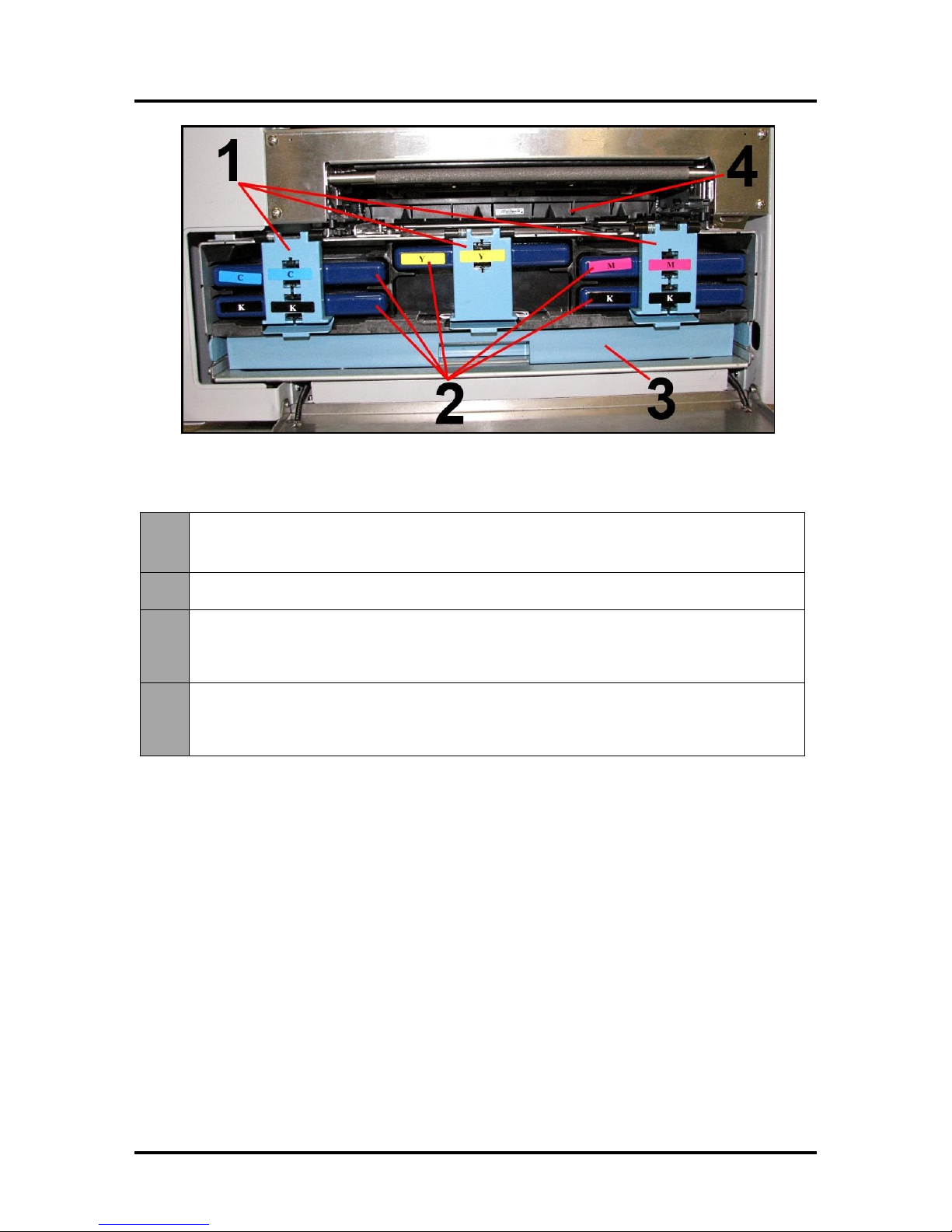
SECTION 1
1.
Ink Tank Securing Latches – Used to hold the Ink Tanks in the slots.
NOTE: Please be sure that both sides at the bottom part of the latch are engaged.
2.
Ink Tanks – Printer has 5 Ink Tanks: Cyan, Yellow, Magenta, Black, Black
3.
Ink Waste Tray – Catches any waste ink produced by the system. Tray is filled with
absorbent material. Tabs located at the left and right sides of the tray secure the tray to
the print engine frame. Please be sure the tabs click in to secure the tray's position.
4.
Service Station – Cleans the Printhead Cartridge of excess ink and debris, keeps the
Printhead hydrated and protected when not in use, captures ink used to keep nozzles
clear, and acts as a base to support media during printing.
GETTING ACQUAINTED
Ink Tank Door View
4
Page 9
SECTION 1
GETTING ACQUAINTED
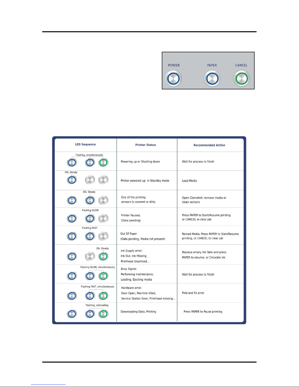
Control Panel Button/LED Indicators
The Control Panel has 3 buttons with LED indicators.
POWER (ON/OFF) – Turns Printer power ON and OFF.
Turn off power for cleaning and maintenance
PAPER (STOP JOB/RESUME) – Stops Paper Feed or
Resumes Printing.
Press to Stop Paper Feed Immediately. Printer
will clear media in Printer and stop.
Press to Resume Printing. Restart printing after a paper feed error (such as a paper jam or
running out of paper).
CANCEL (CANCEL JOB) – Cancels a Job.
Press to Cancel a Job. Once the Printer has stopped, pressing this button clears job from Printer
and Print Queue in Driver. NOTE: Cancelled Jobs must be reloaded before printing can resume.
MORE TROUBLESHOOTING GUIDES on page 54.
FOR A LARGER CHART TO MOUNT ON THE PRINTER, SEE END OF THIS MANUAL.
5
Page 10
SECTION 2
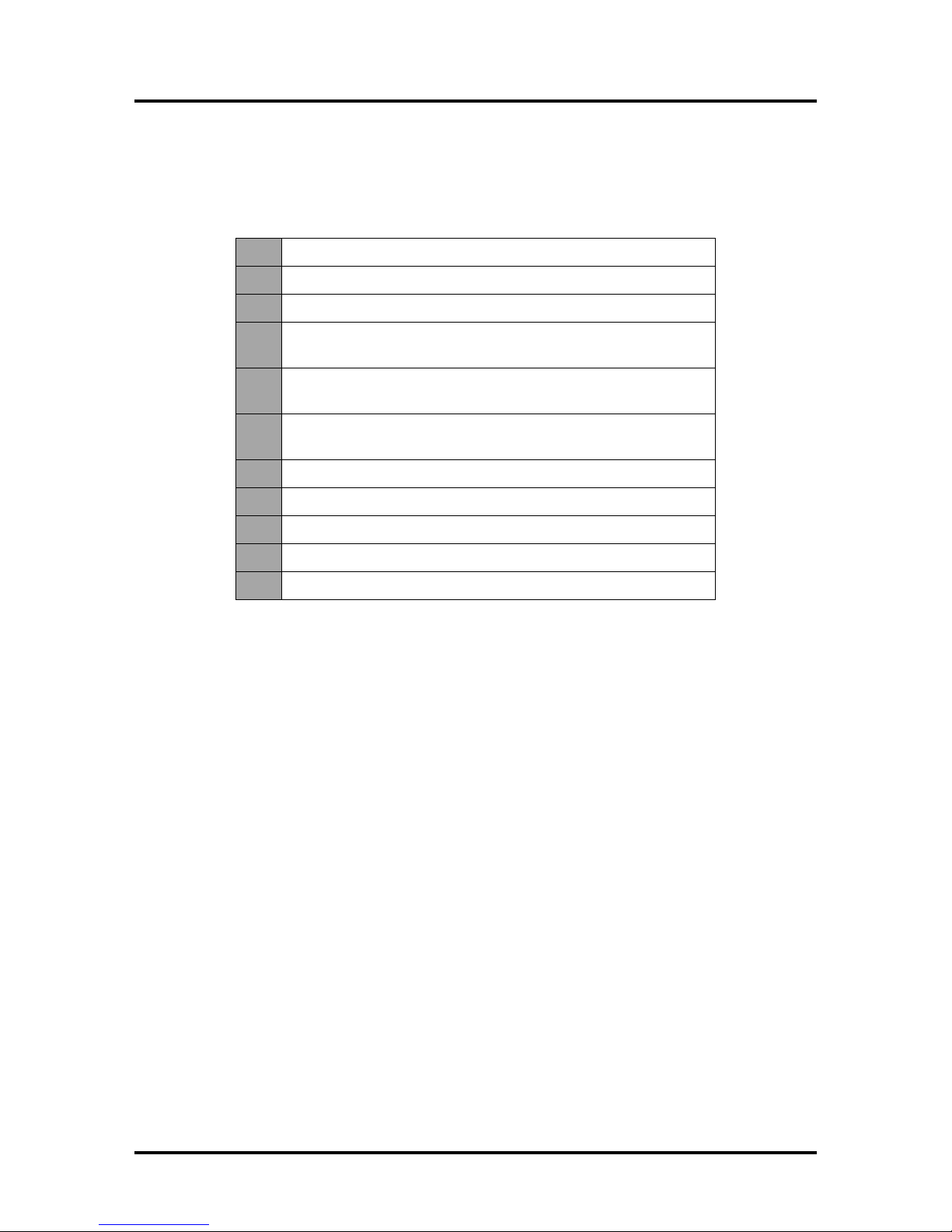
1.
M1 Printer
2.
Ink Tanks – Cyan, Magenta, Yellow, Black, Black
3.
Printhead Cartridge
4.
Media Side Guides: Registration (Fixed) and Adjustable –
mounting screws attached to Printer
5.
Rear Media Support Guide
– thumbscrew attached to Printer
6.
Media Support Wedges: Narrow and Wide
– mounting hardware attached to Rear Media Support Guide
7.
Envelope Attachment Spacers (pkg. of 2)
8.
AC Power Cord
9.
USB Cable
10.
Operator Manual
11.
Driver Software CD
INSTALLING THE PRINTER
SECTION 2 – Installing the Printer
Contents of Packaging
Before using the Printer the following must be done:
Choose a location for the Printer
Unpack and assemble the Printer
Remove the Service Station Transport Tab and Shipping Tape
Plug in the Printer and connect it to the computer
Install the Printer Driver
Install the Ink Tanks
Install the Printhead
Set up the feed on the Printer
Choose a Location
The Printer must be placed on a sturdy level worktable or cabinet at least 9" from any walls. Use the
Bubble Gauge mounted on the Print Engine (or a small level) to make sure the Printer is level. Protect
the Printer from excessive heat, dust, and moisture. Avoid placing it in direct sunlight.
Unpacking and Setup
Remove the Printer and its parts from the carton. Remove all packing tape. The screws that attach the
various parts of the guides to the Printer are under the tape in their respective positions.
6
Page 11
INSTALLING THE PRINTER
CAUTION
HOLD ONTO BOTH LATCHES WHEN OPENING AND CLOSING THE PRINT
ENGINE CLAMSHELL TO PREVENT DAMAGE.
DO NOT ALLOW THE CLAMSHELL TO DROP OR SLAM CLOSED.
TO PREVENT DAMAGE TO THE INK LINES, A STOP LIMITS RAISING THE
CLAMSHELL MORE THAN 60°.
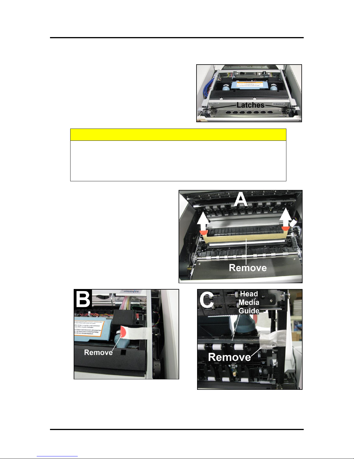
Remove Service Station Transport Tab and Shipping Tape
1. Open the Top Cover.
2. Release the two latches (one on either side of the
Print Engine). Open the top half of the Clamshell by
lifting both levers at the same time.
SECTION 2
3. Remove the cardboard Transport Tab [A]
from the Service Station.
4. Remove the tape [B] securing the Head
Media Guide. (If necessary, wipe off any
tape residue from the Head Media Guide
surface [C].)
5. Carefully close and latch the Upper
Clamshell. Then close the Top Cover.
7
Page 12
SECTION 2
INSTALLING THE PRINTER
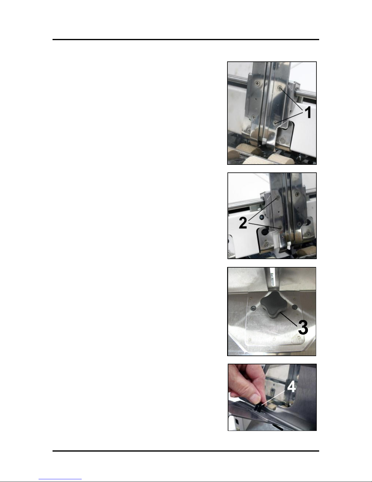
Assembling the Printer
Install the Adjustable Side Guide with two screws [1]:
Install the Envelope/Paper Side Guide with the two screws [2]
provided.
Attach the Rear Paper Support using the knob [3] provided.
NOTE: The two outside holes fit over the socket head screws.
Install the Rear Guide using the thumbscrew and washer [4]
provided. The washer goes between the screw and the Rear Paper
Support.
8
Page 13
INSTALLING THE PRINTER
CAUTION
DO NOT USE AN ADAPTER PLUGS OR EXTENSION CORDS
TO CONNECT THE PRINTER TO THE WALL RECEPTACLE.
DO NOT USE OUTLETS CONTROLLED BY WALL SWITCHES.
DO NOT USE OUTLETS THAT SHARE THE SAME CIRCUIT
WITH LARGE ELECTRICAL MACHINES OR APPLIANCES.
CAUTION
WHENEVER POWERING DOWN UNIT, ALWAYS:
1. PRESS THE POWER BUTTON ON THE CONTROL PANEL.
2. WAIT FOR THE PRINTER TO STOP PROCESSING.
3. THEN PRESS THE MAIN POWER SWITCH ON THE REAR PANEL.
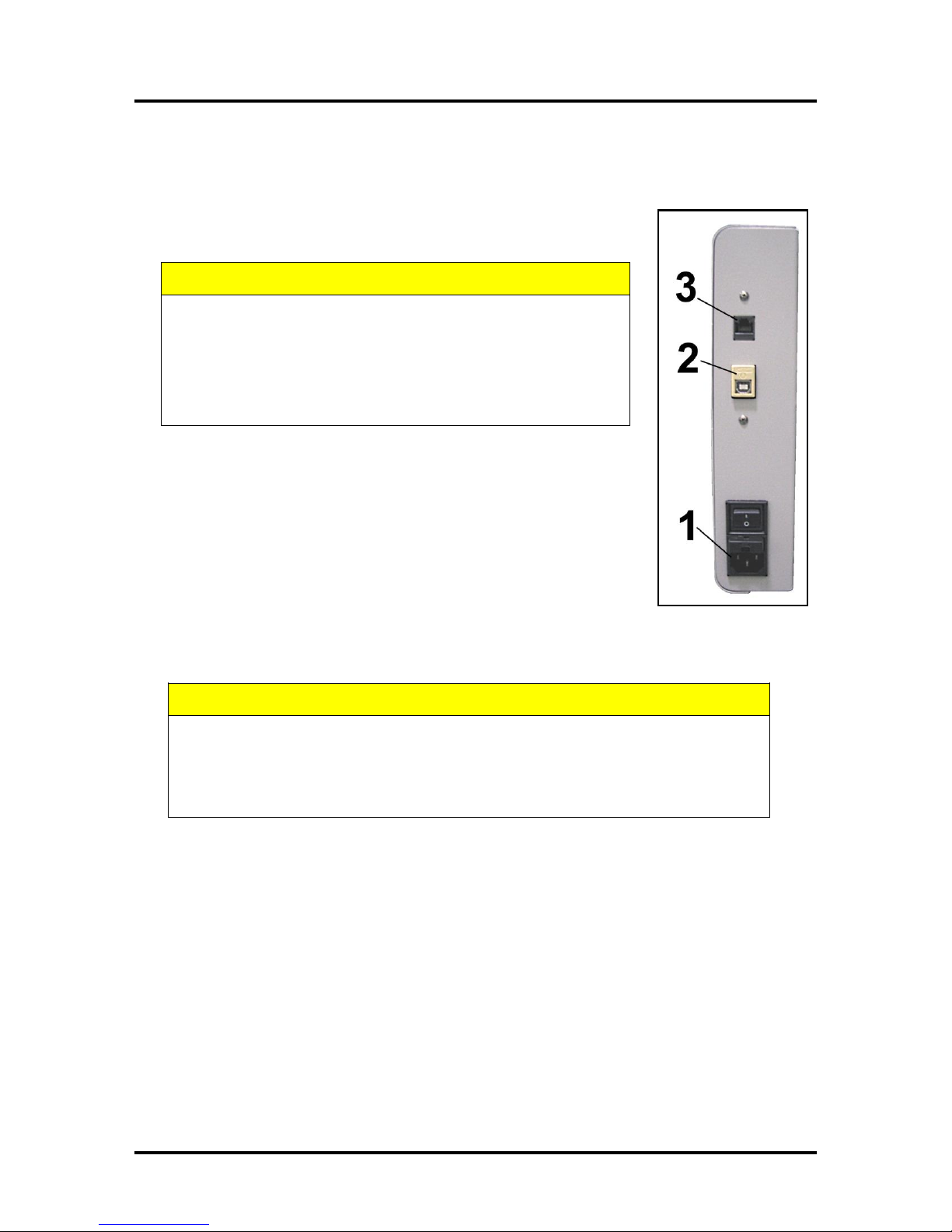
Connecting the Printer
Plugging in the Printer
Plug the power cord into the receptacle [1] at the rear of the Printer. The internal
power supply in the Printer is rated 115 to 240VAC, 50/60 Hz.
Connecting to the Computer
The Printer connects to the computer through the USB Port [2].
A Network Port [3] is provided when operating in a network environment. See
“Network Connection Setup” in the “Using the Printer Toolbox” section.
SECTION 2
Turning Power ON and OFF
Powering Up Printer:
1. Press the Main Power Switch on the Rear Panel.
2. Press the Power Button on the Control Panel.
Powering Down Printer:
9
Page 14
SECTION 2
INSTALLING THE PRINTER
Install the Printer Driver
For the Printer software to operate properly check that the computer system meets these minimum
requirements:
Operating System: Windows XP, Windows Vista, Windows 7, Windows 8/8.1. Supports 32 and 64
bit systems. (You must have administrative privileges on the system.)
NOTE: Win 8 and 8.1 will only work in desktop mode. No Win 8 metro apps will be supported
(applications that work in a Win 8 only environment).
Microprocessor: Pentium II, 2 GHz minimum (Pentium Dual Core, 2.5 GHz or better, is optimal)
System memory: 2 GB minimum; or as recommended for your operating system.
Free hard-disk space: At least 10 GB.
Web Browser: Firefox recommended; Chrome, Safari, and Opera also supported.
CD/DVD drive.
USB 2.0 port (ports will be identified as “USB2” or “Enhanced” in the Device Manager)
Microsoft .Net Framework version 3.5 (for 32 bit systems) or Microsoft .Net Framework version 4
(for 64 bit systems) must be installed. NOTE: Even if you have a higher .NET Framework version
installed; version 3.5 or 4 must also be installed, or the Toolbox will not open.
IMPORTANT: Before installing the Printer software (Toolbox and Driver), you should temporarily
disable all antivirus programs and firewalls. In addition, you must be logged onto the system with full
administrative privileges (admin rights).
NOTE: If installing over USB, do not plug in the USB cable until prompted.
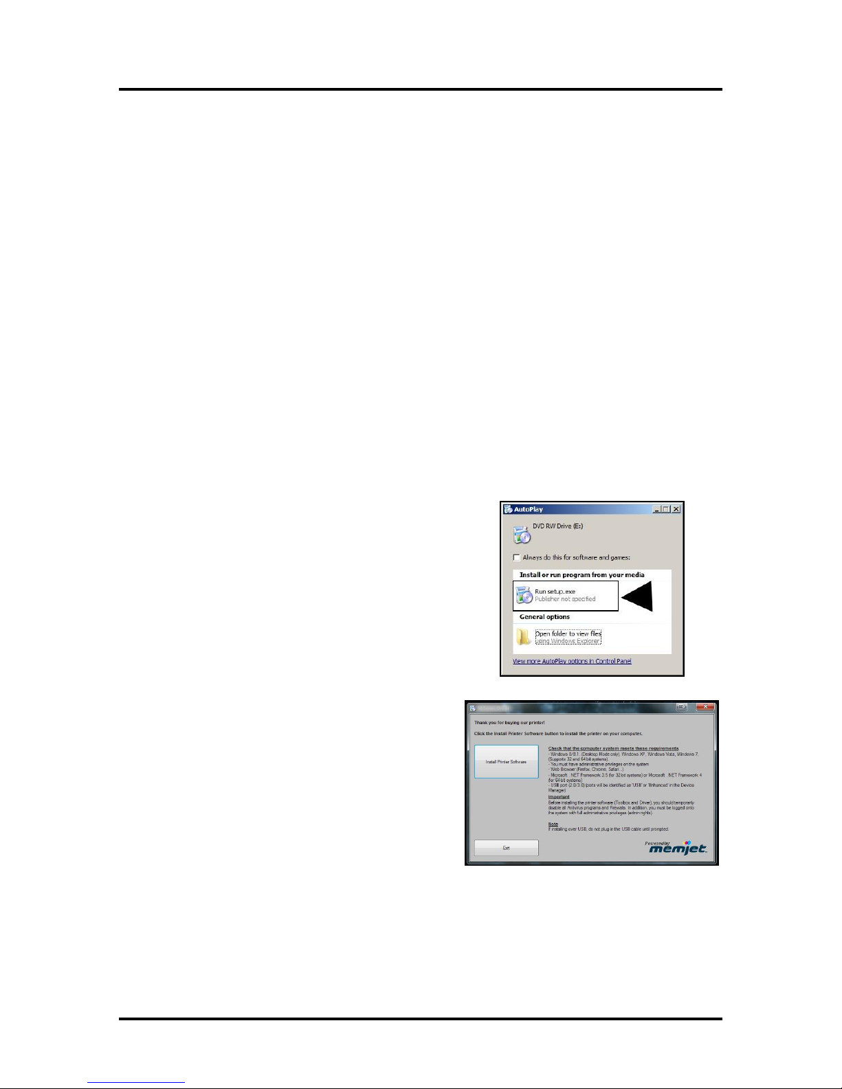
1. Check that Printer is plugged in and turned OFF.
Disconnect the USB connection if you have plugged it
in already. Install the disk supplied with the Printer in
your CD drive. When the AutoPlay Window opens,
click “Run Setup.exe” to start.
2. Install Printer Software. Make sure the computer
system meets the minimum requirements and
you have followed the other instructions listed on
the screen. Click “Install Printer Software”.
10
Page 15
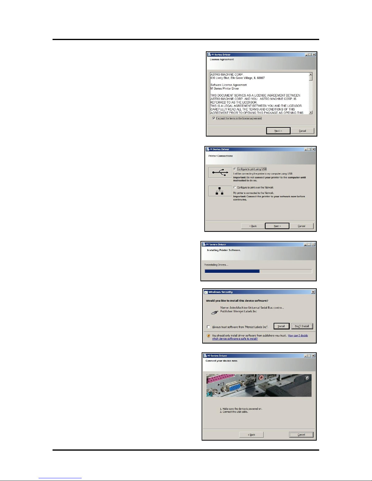
3. License Agreement. Check “I accept…” then
click “Next>”.
4. Printer Connections. Click “Configure to print
using USB”. Then click “Next>”.
SECTION 2
INSTALLING THE PRINTER
5. Installing Printer Software. Software
download begins.
6. Would You Like to Install This Device
Software? Click “Install”.
7. Connect Device Now. Turn Printer ON and
connect the USB cable. Don’t click on either
button. The software will finish installing.
11
Page 16
SECTION 2
INSTALLING THE PRINTER
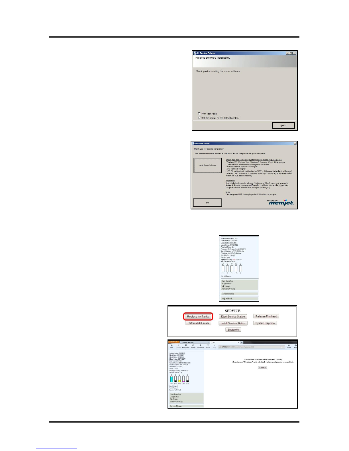
8. Finished software installation. Do not check the
Print Test Page as the Printer is not set up yet.
You can check the “Set this printer as the default
printer” at this time. Click “Next>”.
9. Install Printer Software. Click “Exit” to close
the CD.
10. Restart the computer to complete the installation.
Install the Ink Tanks
The Printer uses one Printhead Cartridge and five Ink Tanks (two
Black, one Cyan, one Magenta, and one Yellow). Install the Ink Tanks
as follows:
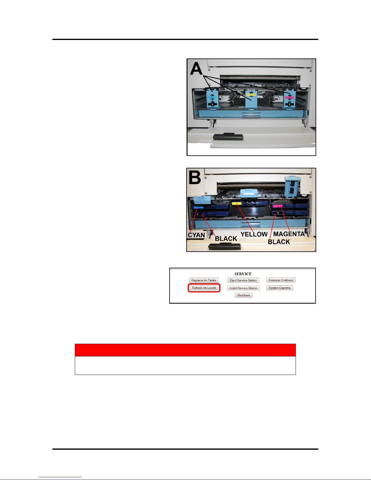
1. Open the Printer Toolbox. Go to the Start Menu and open
the “Toolbox”. You will see System Status information in the
upper left corner of the User Interface window. Note that the
“CKMYK” boxes are empty.
2. Click “Replace Ink Tanks”. This
disconnects Printer communication
with the Ink Tanks and allows safe
installation and replacement. Once the
“Confirm” screen displays, it is safe to
install the Ink Tanks.
IMPORTANT: DO NOT press
“Continue” until after you have
installed the Ink Tank(s) and closed
the Ink Tank Latches.
12
Page 17
WARNING!
The ink in the Ink Tanks may be harmful if swallowed. Keep new and used
Ink Tanks out of reach of children. Discard empty tanks immediately.
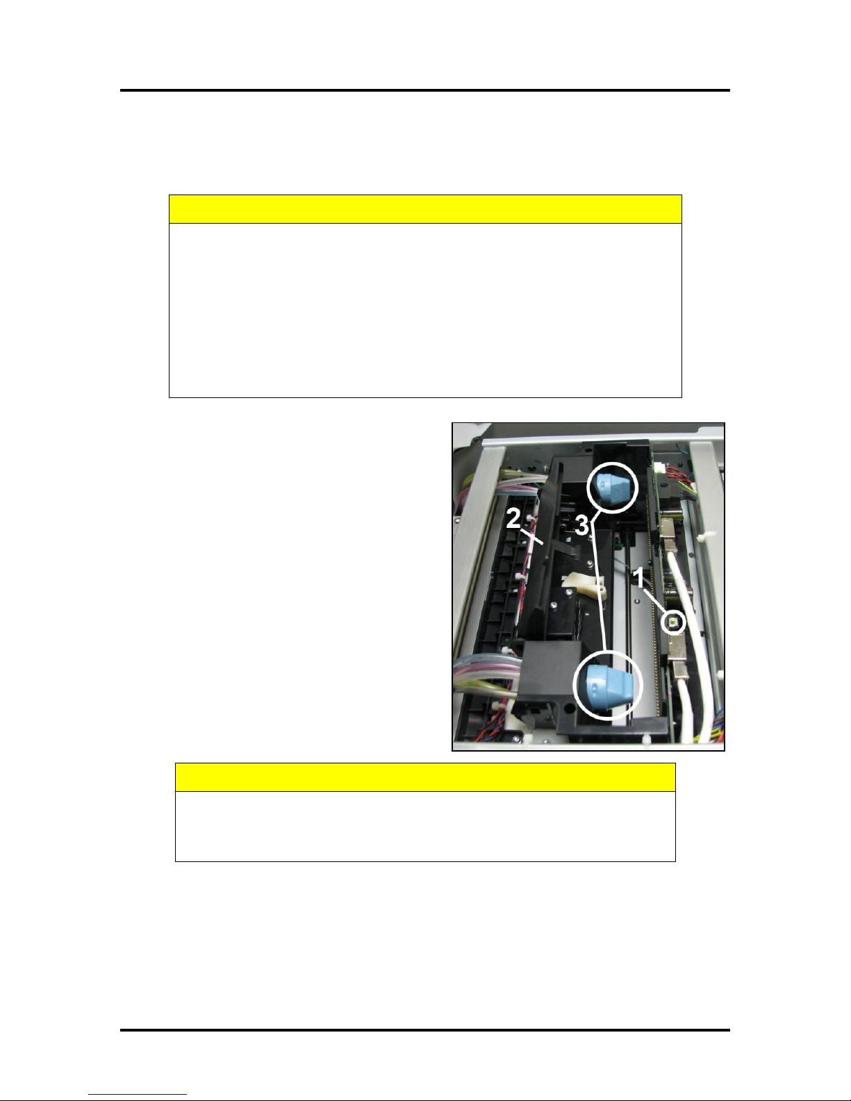
3. Open the Ink Tank Door (hinged at
bottom). Open the three Latches [A].
4. Remove the Ink Tank(s) from packaging.
5. Insert the Ink Tanks (labels up) into their
appropriate color slots [B]. Close the three
Ink Tank Latches.
INSTALLATION TIP: Make sure the
Ink Tanks seat properly. Insert the Ink
Tank into the appropriate Ink Station,
then pull the Ink Tank back about an
inch and push forward firmly to insure
that the Ink Nozzles penetrate the seals
on the Ink Tanks.
SECTION 2
INSTALLING THE PRINTER
6. Click “Continue” on the Confirm
screen, then “Refresh Ink Levels”
on the User Interface screen. The
ink colors fill in as the Ink Tanks
are installed. If the ink colors do not
fill in after a few seconds, click
“Replace Ink Tanks” again and reinstall the Ink Tank(s).
7. Close the Front Cover.
13
Page 18
SECTION 2
CAUTION
Use electrostatic discharge (ESD) protection when handling.
Hold the Printhead Cartridge by the handles ONLY.
DO NOT touch the ink couplings, nozzle surface or electrical contacts.
DO NOT unpack the Printhead Cartridge until the Printer is ready for
installation. Once unwrapped, delay in installing the Printhead can
compromise print quality due to dehydration.
DO NOT place an unwrapped Printhead on any surface before installing.
Protect the Printhead from scratches, dust, fibers, dirt and other
contaminants at all times.
CAUTION
DO NOT PRY OR MANUALLY LIFT THE PRINTHEAD LATCH OR THE
LATCH MAY BREAK. ONLY OPEN THE LATCH USING THE RELEASE
BUTTON ON THE PRINTER OR THE PRINTHEAD RELEASE COMMAND
IN THE PRINTER TOOLBOX.
INSTALLING THE PRINTER
Install the Printhead Cartridge
The Printhead Cartridge is a delicate precision device. Handle with extreme care to avoid damage and
issues that could degrade print quality.
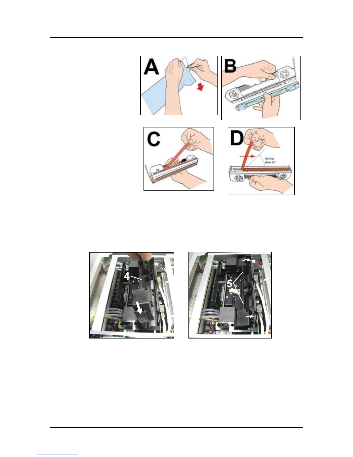
1. With the Printer power ON, open the Top
Cover. Press the Printhead Latch Release
Button [1]. The Printer will run a routine, then
the Latch will pop open [2].
NOTE: Remove the Cap Protectors on the
Ink Nozzles [3]. Be sure to open the Latch
fully to retract the Ink Nozzles.
14
Page 19
2. [A] Carefully remove the
Printhead Cartridge
from the foil packaging.
Tear at notch or cut end
with scissors.
[B] Remove the
protective plastic cover.
Hold the Printhead by the
handle and unclip the
cover from the Printhead.
[C] Remove protective
strip from the Printhead
Electrical Contacts.
DO NOT allow removed
strip to touch the electrical
contacts.
[D] Remove protective
strip from the Printhead
Nozzles. Hold the Printhead
by the handle. Pull the strip tab and slowly peel the strip from
the Printhead.
DO NOT pull the strip at less than a 45° angle from the Printhead surface.
DO NOT allow removed strip to touch the Printhead Nozzles.
SECTION 2
INSTALLING THE PRINTER
3. Carefully insert the Cartridge into the compartment at an angle [4], with the Printhead surface
facing down and the Ink Nozzles facing the Ink Hoses. Once it is seated, gently tilt the Cartridge
back until it snaps into an upright position [5]. DO NOT FORCE the Cartridge into position.
15
Page 20
SECTION 2
CAUTION
HOLD ONTO BOTH LATCHES
WHEN OPENING AND CLOSING
THE PRINT ENGINE CLAMSHELL
TO PREVENT DAMAGE.
DO NOT ALLOW THE CLAMSHELL
TO DROP OR SLAM CLOSED.
TO PREVENT DAMAGE TO THE INK
LINES, A STOP LIMITS RAISING
THE CLAMSHELL MORE THAN 60°.
INSTALLING THE PRINTER
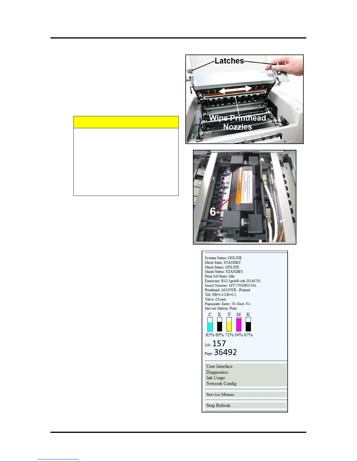
4. Wet the Printhead Surface. This ensures
that the Printhead will prime correctly.
Open the Top Cover. Release and lift the two
latches at the same time to raise the Print
Engine Clamshell. Moisten the Printhead
nozzles using distilled water and a damp,
lint-free cloth, wiping end to end. (Gray
strip located below orange strip.) Close and
latch the Print Engine Clamshell.
5. Close the Printhead Latch [6]. The Printer
will start up and prime ink into the Printhead.
This may take a few minutes. Make sure that
ink is flowing through the hoses.
6. Watch the Toolbox screen. Notice that some of the
information is in red. As the Printer circulates ink
and primes the system these fields should turn black.
7. When the Printer stops processing and all the fields
in System Status are black, the Printer is ready for
use. Close the Top Cover.
NOTE: The Printer may take up to 12 minutes to set
itself up during initial startup. This is normal.
16
Page 21
SECTION 2
CAUTION
HOLD ONTO BOTH LATCHES WHEN OPENING AND CLOSING THE PRINT
ENGINE CLAMSHELL TO PREVENT DAMAGE.
DO NOT ALLOW THE CLAMSHELL TO DROP OR SLAM CLOSED.
TO PREVENT DAMAGE TO THE INK LINES, A STOP LIMITS RAISING THE
CLAMSHELL MORE THAN 60°.
INSTALLING THE PRINTER
Removing the Head Media Guide
You can remove the Head Media Guide if you are primarily printing on thin, flat stock (that is, you are not
printing large batches of envelopes) and are encountering print quality issues. The attachment is used to
flatten the envelope flap for better print consistency.
1. Open the Top Cover
2. Open the Print Engine Clamshell.
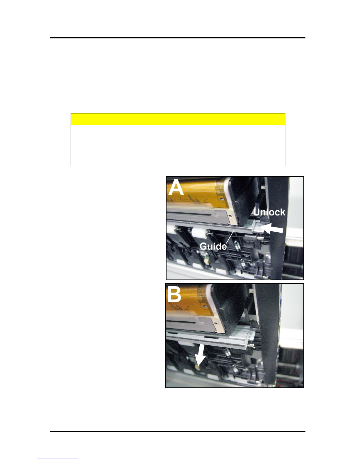
3. [A] & [B] Slide the Envelope
Printing Attachment to the left and
pull down on the Head Media Guide
to release it from the metal support.
[C] Remove the Guide from the
Printer. Save for later use.
17
Page 22
SECTION 2
INSTALLING THE PRINTER
Install/Remove Envelope Attachment Spacers
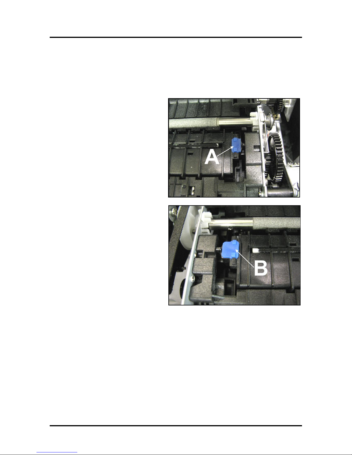
Install the Envelope Attachment Spacers if you are printing large volumes of envelopes. Remove the
Spacers if you are primarily printing sheet stock. DO NOT use the spacers without the Envelope
Attachment (Head Media Guide).
Install:
1. Insert the right-hand Spacer (smaller)
into the hole in the Service Station
Platen [A].
2. Insert the left-hand Spacer (larger) in
the hole on the left end of the Service
Station Platen [B].
3. Wipe the Printhead Nozzles end to end
using distilled water and a damp lintfree cloth. Close and latch the
Printhead Clamshell. Close Top Cover.
Remove:
1. Carefully pull out the right-hand
Spacer (smaller) in the hole in the
Service Station Platen [A].
2. Carefully pull out the left-hand Spacer
(larger) in the hole on the left end of
the Service Station Platen [B].
3. Wipe the Printhead Nozzles end to end
using distilled water and a damp lintfree cloth. Close and latch the
Printhead Clamshell. Close Top Cover.
NOTE: When removing the Head Media
Guide or servicing or replacing the Service
Station, DO NOT discard the 2 Spacers,
remove and save or reuse.
18
Page 23
SECTION 2
INSTALLING THE PRINTER
Setting up the Feed
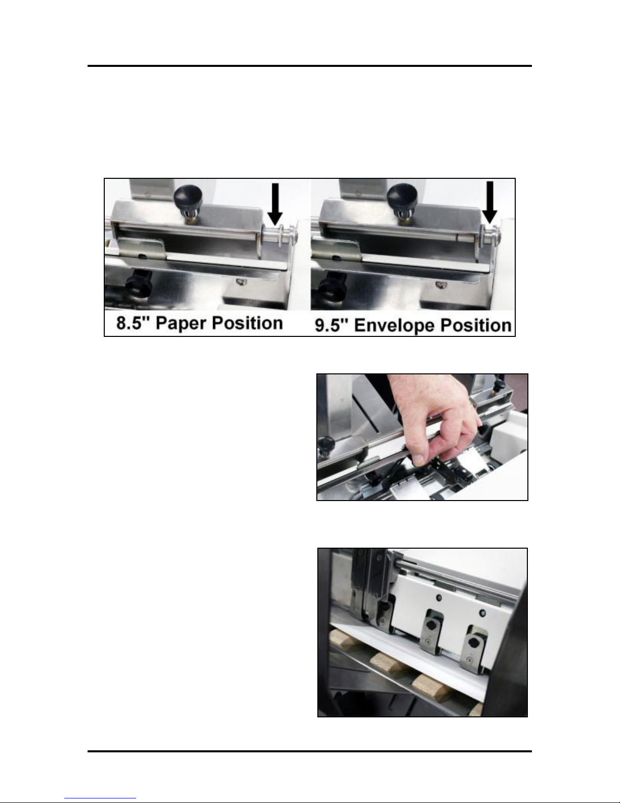
The Printer is equipped with four Sheet Separators, two Side Guides and a Rear Media Guide. The Sheet
Separators are adjusted individually as follows:
1. Move the Left-hand Side Guide into position. This Guide has two positions. The position closest
to the Side Frame is for 9.5" media and the position closest to the center of the Printer is for
printing 8.5" wide media edge to edge.
2. Loosen the locking screws located behind
the Sheet Separators and raise the
Separators, then tighten the locking screws
to hold the Separators in the “Up” position.
3. Place a single piece of the media to be run
under the Separators. Always place the
media against the Left-hand Paper Guide.
Loosen the Separator locking screw and
allow the Separator to settle onto the media.
Then tighten the locking screw. Repeat for
each Separator.
19
Page 24
SECTION 2
INSTALLING THE PRINTER
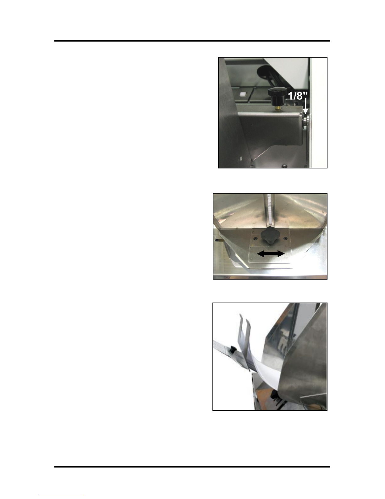
4. Adjust the Right-hand Side Guide so that it is about
1/32-inch from the sides of the media. Tighten the
locking knob on the Side Guide. Place a stack of
media in the machine. Press and hold the Paper key
to feed one piece through the Separator.
NOTE: To prevent misfeeds and tearing, keep
the Right-hand Side Guide at least 1/8" from the
Side Frame.
5. Adjust the Rear Guide Support by using the knob
to slide the Guide right and left. If you experience
feeding problems, slide the Rear Support Guide
right or left keep the media aligned with the
Media Guides.
6. Adjust the Rear Media Guide by loosening the
locking screw and moving the Guide to raise the
media approximately 2" above the Feed Table for
paper and about 1/2" for envelopes.
NOTE: The amount of media that can be stacked on
the Printer is determined by the weight of the
material. The Feeder may not feed larger and
heavier media when the stack is full. If this is the
case, reduce the amount of media in the stack until
the Feeder functions properly.
20
Page 25
SECTION 3
OPERATING THE ASTROJET M1
SECTION 3 – Operating the M1 Printer
Once the Printer Driver is installed on your computer and the Printhead is primed, you are ready to start
printing. Set up your job and send it to the Printer. The Printer will start and print.
This rest of this section is divided into two parts:
1. How to set up a job to print from Microsoft Word.
2. Driver properties and the various options available when you run a job.
The Printer Driver that you installed on your computer in Section 2 should be set as the default driver. It
will then be accessible through your applications such as Microsoft Word. Other types of applications and
database management software will work in a similar manner when using this Driver. This Section further
assumes that you have set up the feed and the Printer is connected to your computer.
Setting Up a Job in MS Word
When setting up a job to print in MS Word or any other
application, first determine the print area of the Printer and
the paper sizes it can handle.
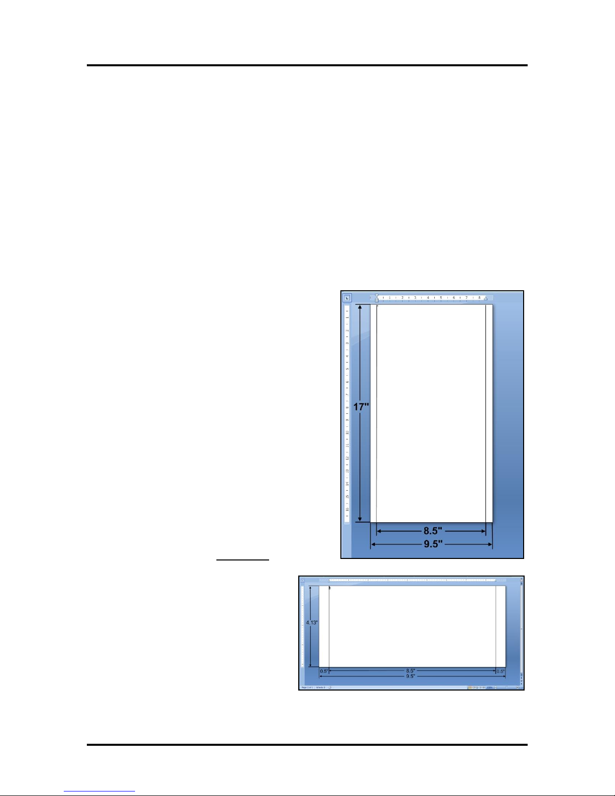
Maximum print area for the Printer:
8.5" wide x 17" long.
Maximum paper size Printer can feed:
9.5" wide x 17" long. (See diagram at right.)
Minimum paper size Printer can feed:
3" wide x 4.2" long.
To set up the maximum print area for a 9.5" x 17"
document, set the paper size to 9.5" wide by 17" long in the
Custom Paper setting. Set top and bottom margins to 0" or
any margin you require. Set right-hand and left hand
margins to 0.5". You can now layout the job and print the
maximum printing area.
For other page sizes such as 8.5" x 11" (standard letter) or
8.5" x 14" (legal size) set the paper size to the exact size
and set the margins as needed.
NOTE: Set the Left-hand Side Guide to the 9.5"
position when running 9.5" wide media. Set the Guide
to the 8.5" position with 8.5" or narrower media.
Envelopes: Select an envelope (example uses a
#10 envelope) from Page Setup in MS Word.
Feed the envelope by the 9.5" inch width, the
fastest way to run envelopes especially if you are
addressing them with a Mail Merge. Set the top
and bottom margins to 0", the left and right
margins at 0.5" as shown.
21
Page 26
SECTION 3
OPERATING THE ASTROJET M1
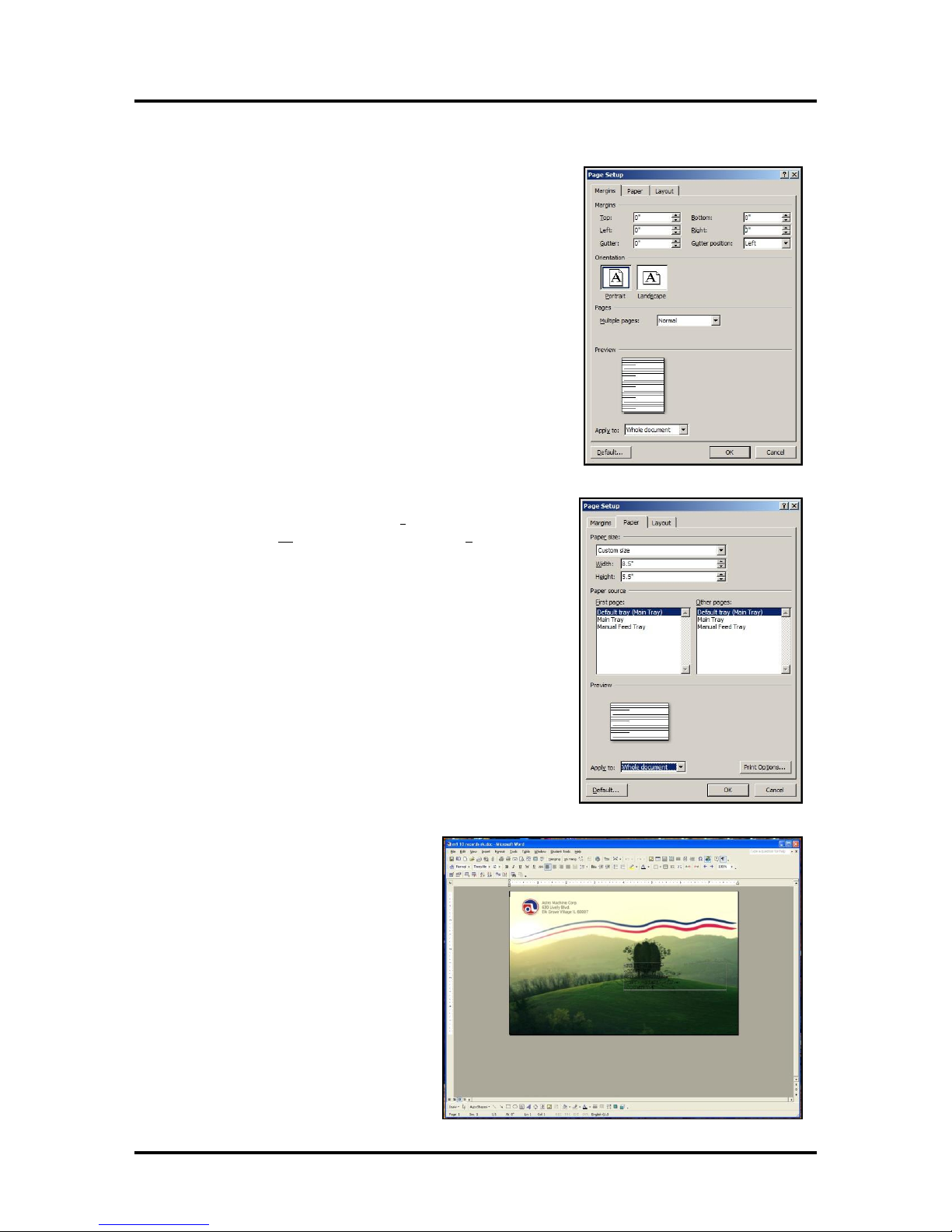
Printing a Typical Job on 8.5-inch by 5.5-inch Paper
The Printer can print edge-to-edge on an 8.5" x 5.5" document.
Follow these steps to set up a job:
1. Go to File, then Page Setup and select 0" margins.
2. Select the Paper tab, select Paper Size “Custom size” then
set the paper Width to 8.5" and the paper Height to 5.5".
Then click OK.
3. The screen at right is an example of a
job to be printed. Once the job is
ready for printing, select “Print”
from the File menu and print the job.
For more information about changes that
can be made in the Driver please see the
Printer Driver section.
22
Page 27
SECTION 3
NOTE: Default setting (Reverse
Order unchecked) prints the job
starting with the first page. Printing
starts as soon as first page loads.
Reverse Order allows the job to start
printing from the last page. Since the
entire job has to load into the Printer
before printing starts, large jobs may
take longer to load.
OPERATING THE ASTROJET M1
Printer Driver Properties
The Printer Driver for the Printer works the same as any other Printer Driver for Windows. It does have
some enhancements to help you maximize the ability of the Printer to print variable addressed pieces
quickly and efficiently.
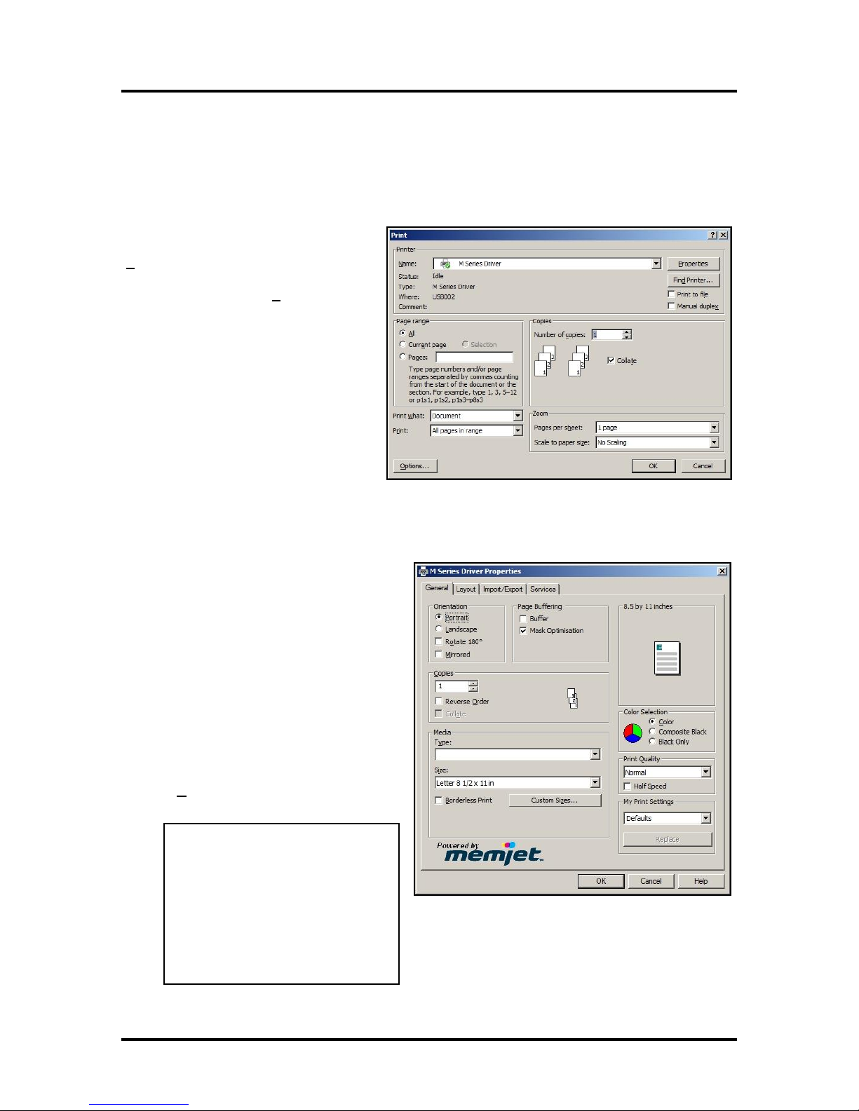
Windows XP, Vista, Windows 7,
Windows 8: Once the job is set up, click
File, then Print. The window at right
opens. Make sure the M Series Driver is the
selected Printer. Clicking Properties opens
the “Properties” window.
General Tab
The General tab lets you select:
Orientation – Portrait (default),
Landscape, Rotate 180° and Mirrored.
Page Buffering – Loads entire print
job before printing starts. Mask
Optimization (checked is default)
optimizes images for printing in most
applications.
NOTE: Some applications (like
FlexMail) may display image
boundaries when printed, unchecking
the Mask Optimization box eliminates
these lines. (Remember to check box
when changing applications.)
Copies – Enter the number of copies to
be printed.
23
Page 28
SECTION 3
MEDIA PROFILE
MEDIA TYPE
Plain Paper
Plain Paper
Bright White Paper
Matte Paper
Presentation Paper
Postcards Matte
Brochure Matte
Labels Matte
Other Inkjet Paper Matte
Premium Matte Coated Paper
Premium Inkjet Paper
Premium Photo Paper Matte
Glossy Paper
Photo Paper Semi-gloss
Photo Paper Glossy
Labels Glossy
Postcards Glossy
Brochure Glossy
Premium Glossy Paper
Premium Photo Paper Glossy
OPERATING THE ASTROJET M1
Media – Choose a type of media or
different size media than the
document was originally designed
for. Type: Chart at right lists the
media profiles associated with the
type of media chosen. Sizes: 21 sizes
are available. The document is
automatically resized to fit the new
media. You can also create and save
a Custom Size to suit your needs.
NOTE: Do not exceed maximum
paper size for the Printer.
Color Selection – Set Printing for
Color, Composite Black (uses all
colors to print Black), or Black Only
(uses only Black ink).
Print Quality – Select Normal or Best. Normal is 1600 x 800 dpi, checking the “Half Speed”
box slows printing for higher quality on glossy stock. Best setting is 1600 x 1600 dpi, for use
when high quality images are required.
My Print Settings – Access your saved custom print settings for various jobs.
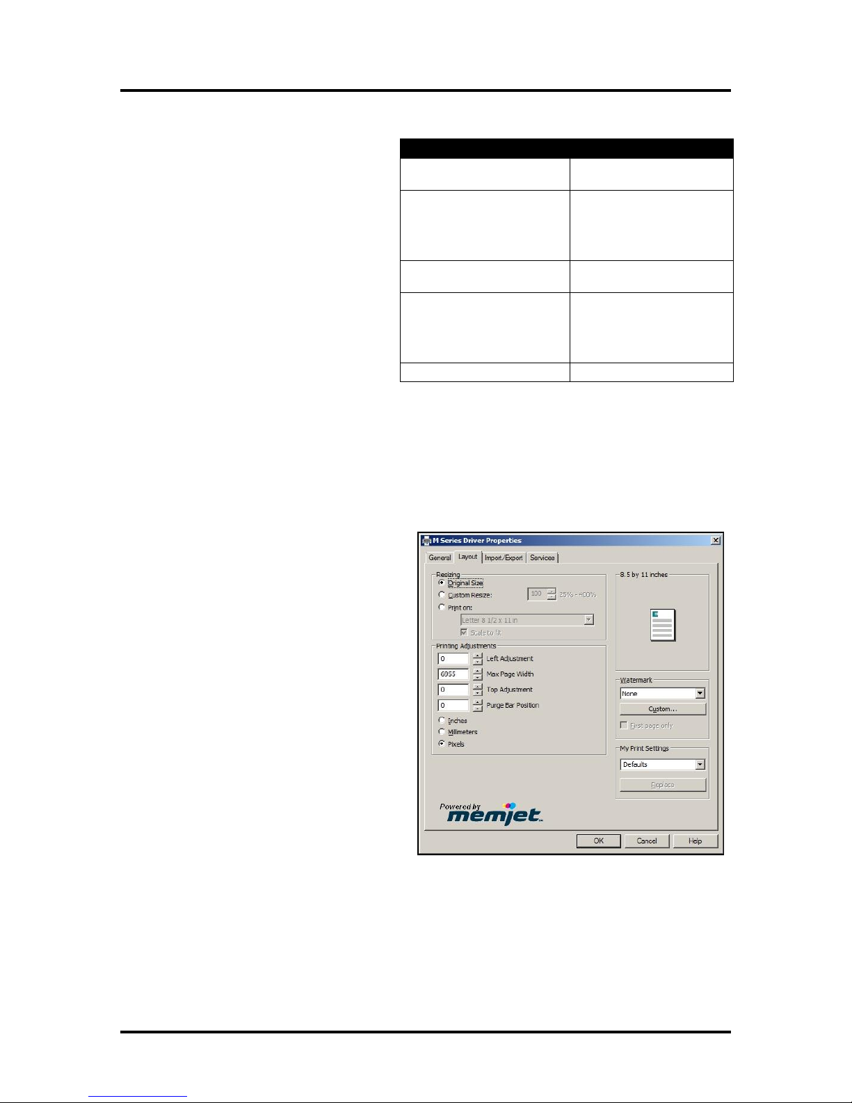
Layout Tab
Layout allows you change how the document
prints without changing the original document.
Resizing – Specify Original Size or
Custom Resize: Resizes the original as
a % of normal size. The Printer prints
the document in the size you selected
regardless of the paper size selected.
Print on: Specify the particular size of
paper that you want to print on
regardless of the size of the original
document. Checking “Scale to Fit”
automatically resizes the document to fit
on the new page size.
Printing Adjustments – Make minor
positioning changes to the print area in
relation to the media if needed. You can
also set the measurements to be in
Inches, Millimeters or Pixels.
NOTE: Printing Adjustments only
works when Print Area is less than the
full print width (less than 8.5/215.9mm
wide). See “Using Layout Tab Printing Adjustments” on next page.
24
Page 29
SECTION 3
OPERATING THE ASTROJET M1
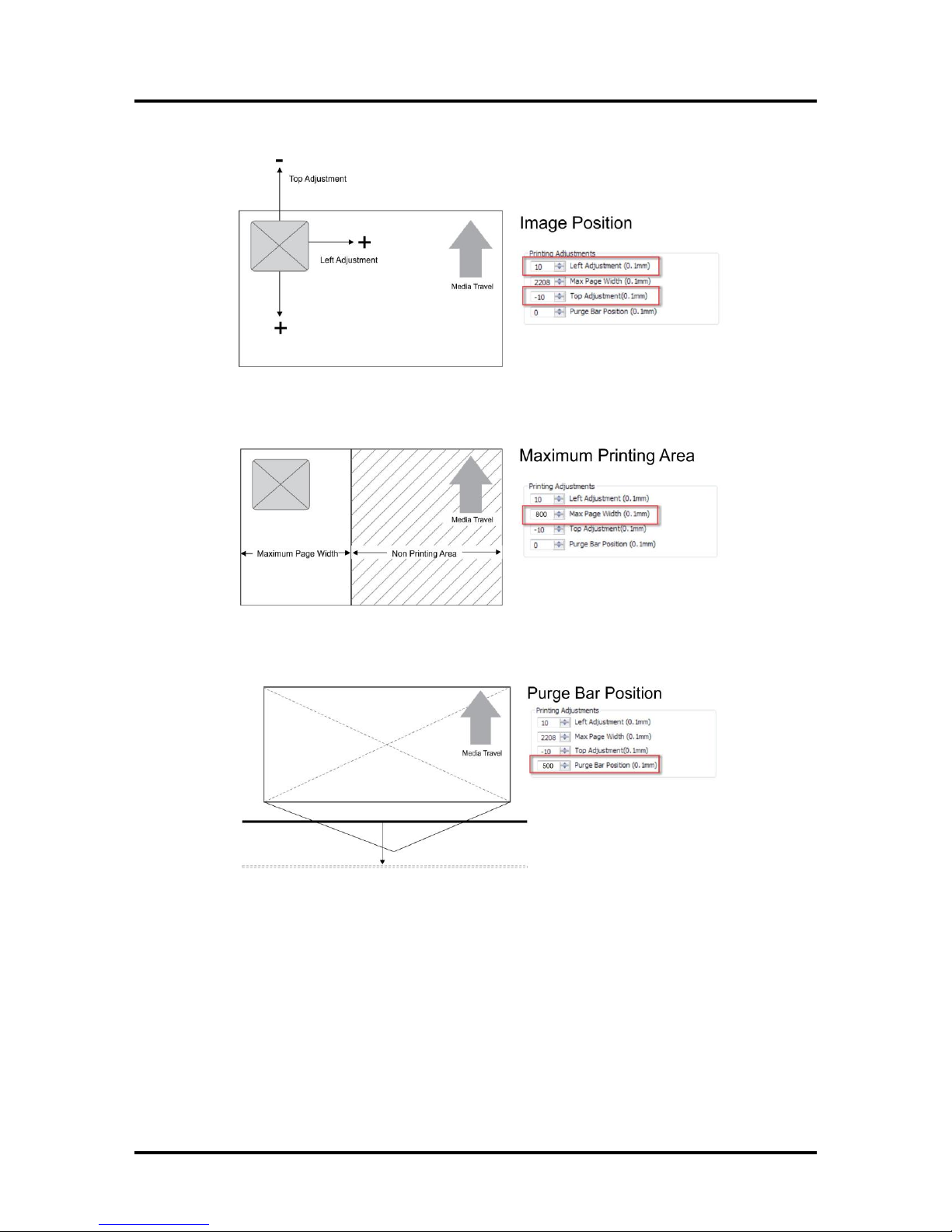
Using Layout Tab Printing Adjustments
Image Position – Left Adjustment moves the image area away (-3mm left to +200mm right)
from the left edge of the media. Top Adjustment moves the image up or down
(-5mm up to +200mm down) from the top left corner of the media used. (0.1mm increments)
Max Page Width – Sets the width of the actual print area. (0.1mm increments) This shuts off
the nozzles in the non-printing area (not used for printing) and saves ink. NOTE: Can be no
larger than the maximum print width for the printer (8.5"/215.9mm).
Purge Bar Position* – In operation, the Printhead spits a small amount of ink in the gap
between pieces to keep the nozzles refreshed. For irregular-shaped pieces (like an envelope
flap), the sensor may “read” the lower end as the edge and spray on the tip of the flap instead
of the actual gap between pieces. This feature allows you to manually set the gap (in 0.1mm
increments) to account for the extra length needed to reach the actual gap.
* See also “Purge Bar Position” in the Printer Toolbox section.
Watermark – Prints a light background watermark in the paper while printing the original
document. When this option is selected the “First page only” option prints the watermark on the
first page, but not subsequent pages, unchecking prints the watermark on all pages. The Custom
button lets you create a new watermark or edit an existing watermark, including font selection,
color, size and printing angle.
My Print Settings – Access your saved custom print settings for various jobs.
25
Page 30
SECTION 3
IMPORTANT!
BEFORE UPDATING ANY PRINTER FIRMWARE, REMEMBER TO FIRST EXPORT ANY
CUSTOM MEDIA SIZES, WATERMARKS OR
PRINT SETTINGS YOU HAVE ADDED TO AN
OUTSIDE HOLDING FILE. THIS PREVENTS
THE LOSS OF YOUR CUSTOM SETTINGS.
OPERATING THE ASTROJET M1
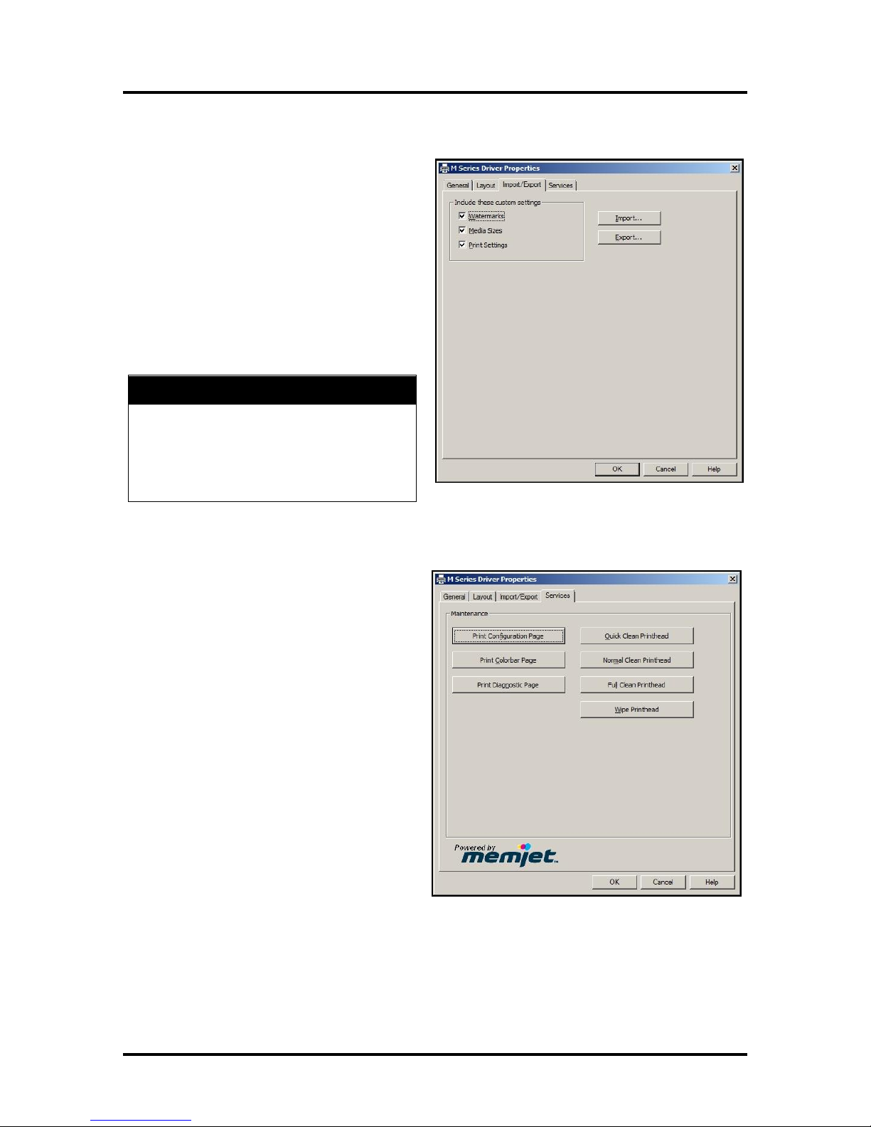
Import/Export Tab
Import/Export is used to preserve any custom
Media Sizes, Watermarks and/or Print Settings you
may have developed and saved for various jobs
when you update the Printer firmware.
Export – Send the custom settings to a
holding file before downloading the new
firmware.
Import – Return the custom settings after
the firmware installation is complete.
This tab is also used to import custom media size
packages or watermarks from your dealer if they
are available.
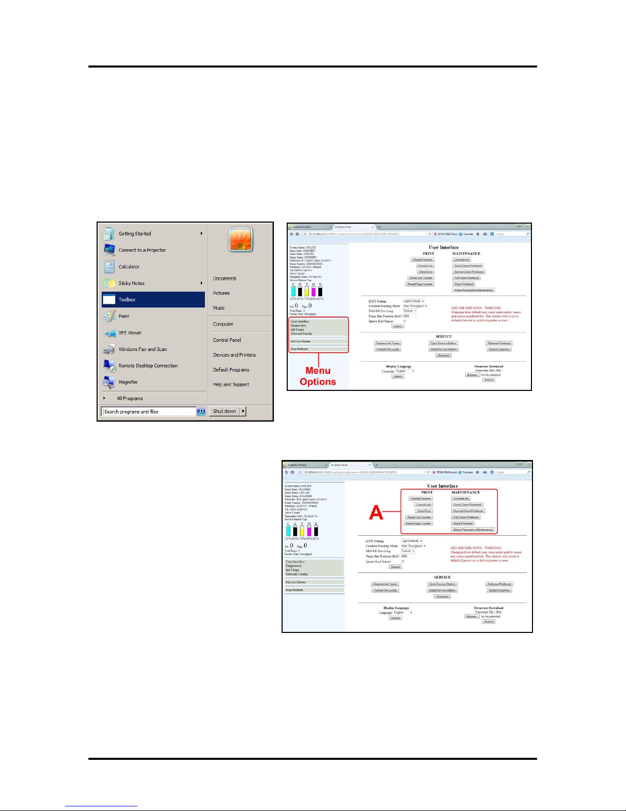
Services Tab
Services allows you to:
Print Configuration Page – Prints out
the current configuration of the Printer
including current Firmware Version,
Network Connection, printer Serial
Number and more.
Print Colorbar Page – Prints type and
color bands to check print quality.
Print Diagnostic Page – Displays basic
Printer information, memory, Network
Settings, Event Log and RAM partitions.
Clean Printhead Buttons: Provide 3
levels of cleaning for the Printhead
Cartridge.
Quick Clean Printhead – Circulates ink,
wipes and cleans the Printhead Cartridge.
Normal Clean Printhead – Runs
cleaning and wiping routine twice for
better flushing and cleaning.
Full Clean Printhead – Runs the
cleaning routine multiple times for the most thorough flushing and cleaning of the Printhead.
NOTE: If the Printer is connected to a network and the Driver buttons fail to activate the
cleaning process, you can perform the same functions from the Toolbox User Interface.
Wipe Printhead – Wipes and cleans excess ink from the Printhead Cartridge.
26
Page 31
SECTION 3
OPERATING THE ASTROJET M1
Using the Printer Toolbox
Once the Printer Driver is installed you have access to the Printer Toolbox. The Toolbox lets you check
printer status, monitor ink usage, perform diagnostic checks, print reports and run maintenance tasks on the
Printer from your computer.
To open the Toolbox:
Open the Start Menu then click on Toolbox. When the User Interface window opens you will find a series
of Menu Options you can click on at the lower left of the screen. You can check the Printer Status in the
upper left part of the screen.
User Interface
[A] Screen Buttons: Perform maintenance
and operating tasks.
PRINT buttons:
Pause/Resume, Cancel a Job, Clear
Errors, Reset the Job Counter, and Reset
the Page Counter.
MAINTENANCE buttons:
Circulate Ink – Purges air from the lines
and primes the system after replacing the
Ink Tanks or Printhead Cartridge.
Quick Clean Printhead – Circulates ink,
wipes and cleans the Printhead Cartridge.
Normal Clean Printhead – Runs
cleaning and wiping routine twice for better flushing and cleaning.
Full Clean Printhead – Runs the cleaning routine multiple times for the most thorough flushing and
cleaning of the Printhead.
Wipe Printhead – Activates the Service Station to wipe the Printhead.
Wiper Preemptive Maintenance – Re-saturates the Wiper with ink to remove dried residue if the Printer
is inactive for long periods of time.
27
Page 32
SECTION 3
OPERATING THE ASTROJET M1
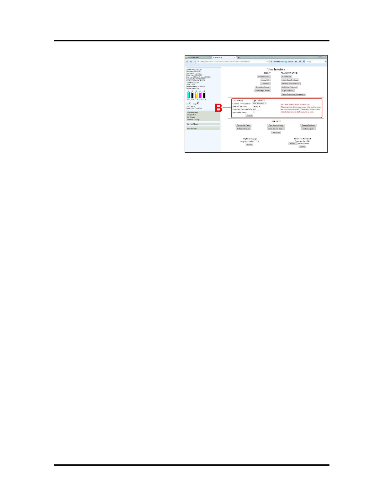
[B] SETUP Settings – Let you adjust automated
service and cleaning intervals, adjust the feeder
speed for a job, manually set the gap between
pieces and adjust the Printer for pre-printed
media.
KWS Setting – (Keep Wet Spitting) Keeps
Printhead hydrated while running a job. Select
from 3 settings: None, Light (default), Heavy,
to determine how much ink will “spit” from
the Printhead Nozzles. Set in conjunction with
“Mid-Job Servicing” which determines the
frequency of the Printer stopping for selfservicing during a job.
Cutsheet Feeding Mode – Permits you to change how the Printer feeds media depending on the type of
job you are running:
Safe Feed – Leaves a larger gap between pieces to reduce overprinting onto the next piece. This
setting is useful for more intricate printing jobs or jobs requiring the best print quality.
Max_Throughput – Allows fastest printing speed. The Printer works like a stream feeder. This
setting is useful for simple printing jobs. NOTE: A few extra blank pieces may run through at the end
of the job.
NOTE: These two settings can be changed without stopping the job. Example: While running a job
in “Max-Throughput” you find that the media is jamming excessively due to speed. Open the
Toolbox, check “Safe Feed” and click “Submit”. The Printer will automatically adjust without
having to pause or stop the job.
Mid-Job Servicing – Sets the frequency of automatic maintenance cycles run during a job after a set
amount of media is run. Settings are: Default (14m), Level 4 (100m), Level 3 (250m), Level 2 (375m),
Level 1 (500m) and Off (. NOTE: Changing the setting from “Default” may cause print quality
issues and reduce Printhead life.
Purge Bar Position – In operation, the Printhead spits a small amount of ink in the gap between pieces to
keep the nozzles refreshed. For irregular-shaped pieces (like an envelope flap), the sensor may “read” the
lower end as the edge and spray on the tip of the flap instead of the actual gap between pieces. This
feature allows you to manually set the gap (1 micron increments) to account for the extra length needed to
reach the actual gap.
Ignore Exit Sensor – Checking this box turns the Exit Sensor OFF. The Sensor may not detect the
trailing edge of a piece of pre-printed media if the back of that media is dark or black. (Example: adding
addresses to a pre-printed postcard.) This may cause the Sensor to react as if a jam has occurred. Turning
the Sensor OFF prevents these “false jams” from stopping the job.
Click “Submit” to apply settings.
28
Page 33
SECTION 3
OPERATING THE ASTROJET M1
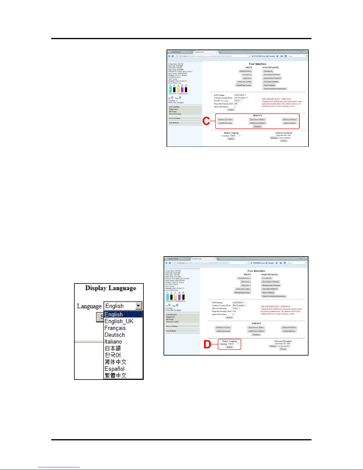
[C] SERVICE buttons control functions
that require the machine to be out of service
for extended periods of time while they are
being performed.
Replace Ink Tanks – Disconnects Printer
communication with Ink Tank Sensor.
Allows safe removal of Ink Tanks for
replacement.
Refresh Ink Levels – Updates or confirms
the ink levels shown at the left of the
screen.
Eject Service Station – Releases the
Service Station for removal for cleaning,
repair or replacement.
Install Service Station – Pulls the Service Station back into place after cleaning, repair or replacement.
System Deprime – Pumps the ink back into
the Ink Tanks prior to replacing the Printhead Cartridge or transporting the Printer.
Release Printhead – Pumps ink back into the Ink Tanks and opens the Printhead Latch to remove or
install the Printhead Cartridge. NOTE: This function can also be performed by pressing the
Printhead Release button on the Print Engine (Control Panel Side).
Shutdown – Turns the Printer OFF. For best system performance, it is recommended to keep the Print
Engine powered-up (ON/OFF light illuminated) at all times. If you do turn the Printer off, first power-
down the Print Engine using the “Shutdown” button in the Toolbox or the ON/OFF button on the Control
Panel. Wait until all of the Control Panel buttons go out before turning off the Main Power Switch.
[D] Display Language – Selects the
language the EWS (Toolbox) will display.
Click “Submit” after selecting language.
29
Page 34
SECTION 3
OPERATING THE ASTROJET M1
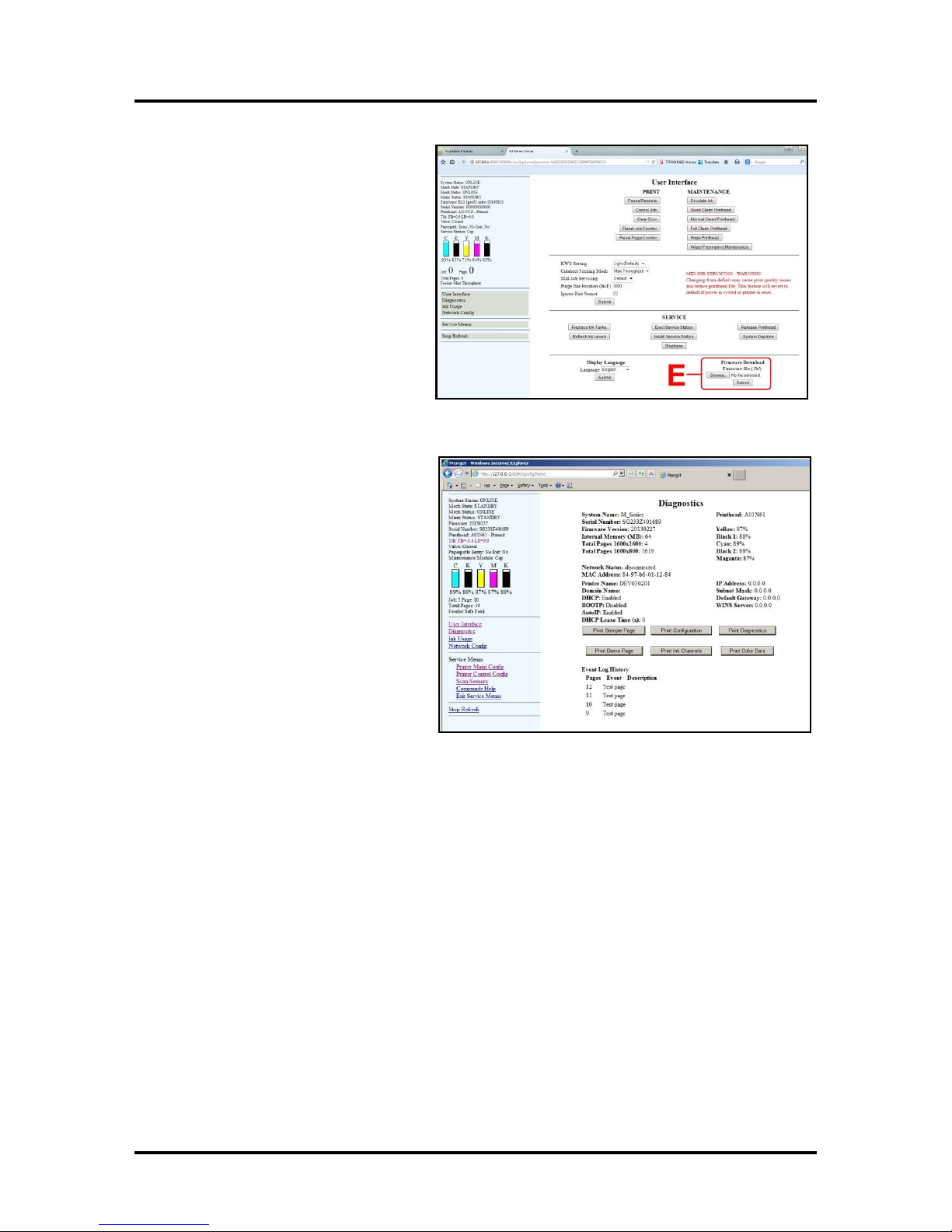
[E] Firmware Download – Get the latest
version of firmware for your Printer.
NOTE: This is an alternative method for
downloading the firmware. See “Updating
Firmware” for the recommended
procedure.
WARNING: This procedure should only be
performed by qualified service personnel.
In some cases firmware must be loaded
using the “Firmware Migration Tool”. If this
process is not performed properly, Printer is
rendered inoperable.
Diagnostics
From this screen you can see the current
status of your Printer. You can also:
Print Sample Page – Prints type and color
bands to check print quality.
Print Configuration Page – Displays the
current configuration of the Printer including
Firmware Version, Network Connection,
Printer Serial Number and more.
Print Diagnostic Page – Displays basic
Printer information, memory, Network
Settings, Event Log and RAM partitions.
Print Demo Page – Prints a 4-color sheet.
Print Ink Channels – Prints 5 bars (1 bar
from each ink tank) to indicate how well the
Printhead Nozzles are working.
NOTE: This function can also be accessed by pressing the “Print Ink Channels” button on the right
side of the Print Engine.
Print Color Bars Page – Prints a series of 7 color bars to indicate how well the Printhead is mixing colors
and printing.
30
Page 35
SECTION 3
OPERATING THE ASTROJET M1
Ink Usage
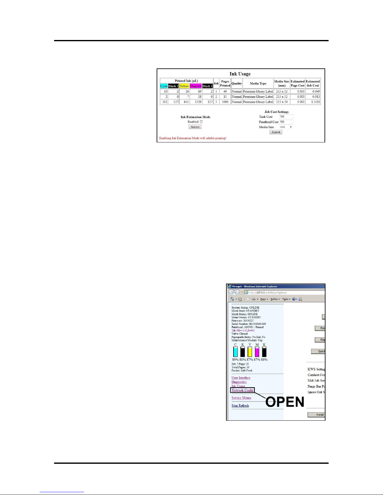
Allows you to monitor the estimated
amount of ink left in each of the five
Ink Tanks. You can monitor ink use
and consumption and schedule Tank
changes (saving down-time during a
print run.) NOTE: Ink Usage only
works when you install a new Ink
Tank and leave it in the Printer.
Ink Estimation Mode – Checking
this box lets you predetermine how
much ink a given job may use prior to
printing a job. This can be useful for determining per piece costs. The job is sent to the Printer and loads,
but does not print. Once the job is loaded, the chart shows the amount of ink (by color) that the job will use.
Click “Submit” to activate or deactivate this feature.
NOTE: The estimating process takes as long as the job would take to print (i.e., if the job would take 1
hour to print, the estimate will take 1 hour to display.)
Job Cost Settings – Enter your ink cost and printhead cost and media size preference (inches or mm). Set a
minimum of at least 100 pcs. to ensure a large enough sample size. Click “Submit”. In Ink Estimation
Mode, this feature estimates your per page cost and your job cost without printing the job. With Ink
Estimation Mode disabled, the Printer will still track your estimated per page cost and estimated job cost as
the job is being printed. NOTE: Remember that this is only an estimate, and does not include other
factors such as Printer maintenance routines, (printhead wiping and cleaning, power up/down, etc.)
that may affect the overall result.
Network Configuration
Permits you to view, enter or change settings to connect the Printer to your network.
Network Connection Set Up:
1. The Printer is still connected to the computer via the
USB cable.
To connect the Printer to a network, open the
Toolbox. On the User Interface page, click
“Network Config.”
31
Page 36
SECTION 3
OPERATING THE ASTROJET M1
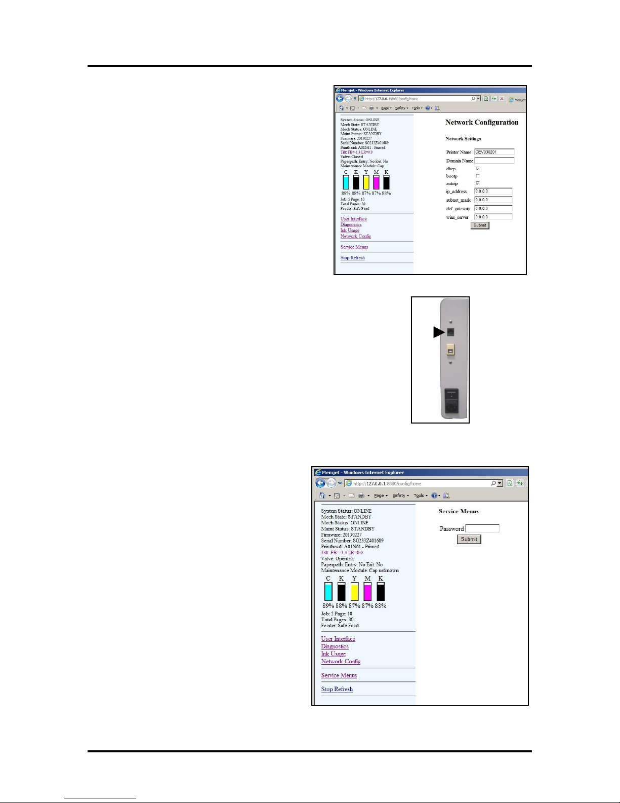
2. The “Network Configuration” page opens.
Use Network Settings to enter the correct
settings for your network.
3. Connect Ethernet cable to Network Port on Rear Panel of Printer.
Service Menu
For authorized personnel only. Provides access to
more advanced Printer control and maintenance
menus.
32
Page 37
SECTION 3
OPERATING THE ASTROJET M1
Updating Firmware
Get the latest version of firmware for your Printer.
NOTE: Use this procedure to update the firmware
AFTER you have updated the Printer Driver. The
Printer Driver update procedure is included with an
“Update Package” which includes both updated
Printer Drivers and firmware updates).
How to download new firmware:
1. When you are notified that new firmware is
available for your Printer, download the
“*.bin” file and save it to your desktop.
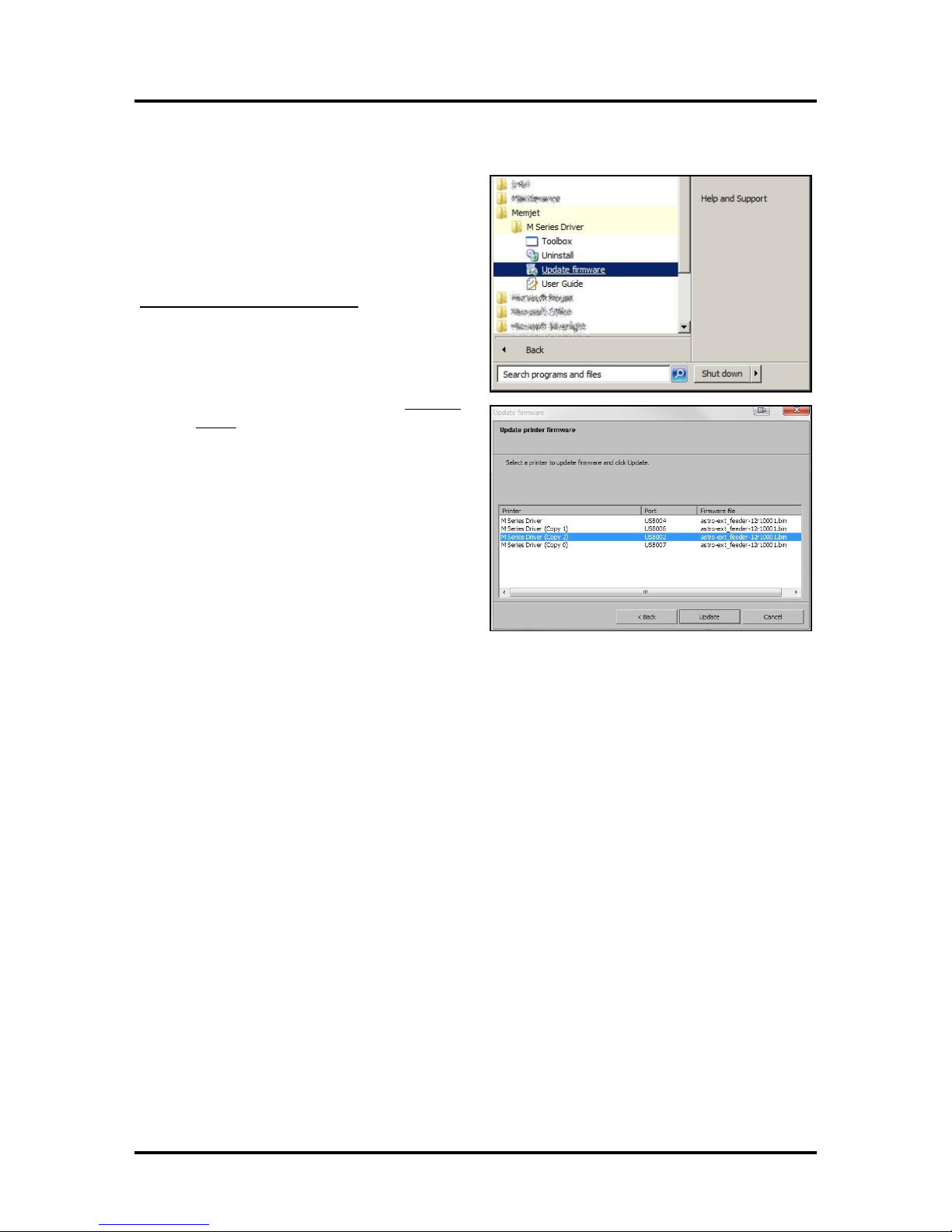
2. From the Start Menu, open All Programs.
Open the “Memjet” folder, then “M Series
Driver”. Click “Update Firmware”.
3. Click the “Browse” button. Find and select
the file you just saved to your desktop.
Click “Open”.
4. When the “Update printer firmware”
window opens, select the M Series printer
you want to update. NOTE: You can only
update one printer at a time.
5. Click “Update”. DO NOT touch the
Printer until the firmware is loaded! A
message appears on the screen warning you
not to unplug or shut off the Printer.
6. Once the firmware finishes loading (about 5-10 minutes), the Control Panel lights and the Printer
shuts OFF, then restarts automatically to complete the installation.
33
Page 38
SECTION 4
MAINTENANCE
SECTION 4 – Maintenance
General, periodic maintenance is needed to keep the Printer in good working order. This section covers
how to care for the Ink Tanks, Printhead Cartridge, Service Station, and clear paper jams.
Replacing the Ink Tanks
Replace the Ink Tanks when the ink runs out.
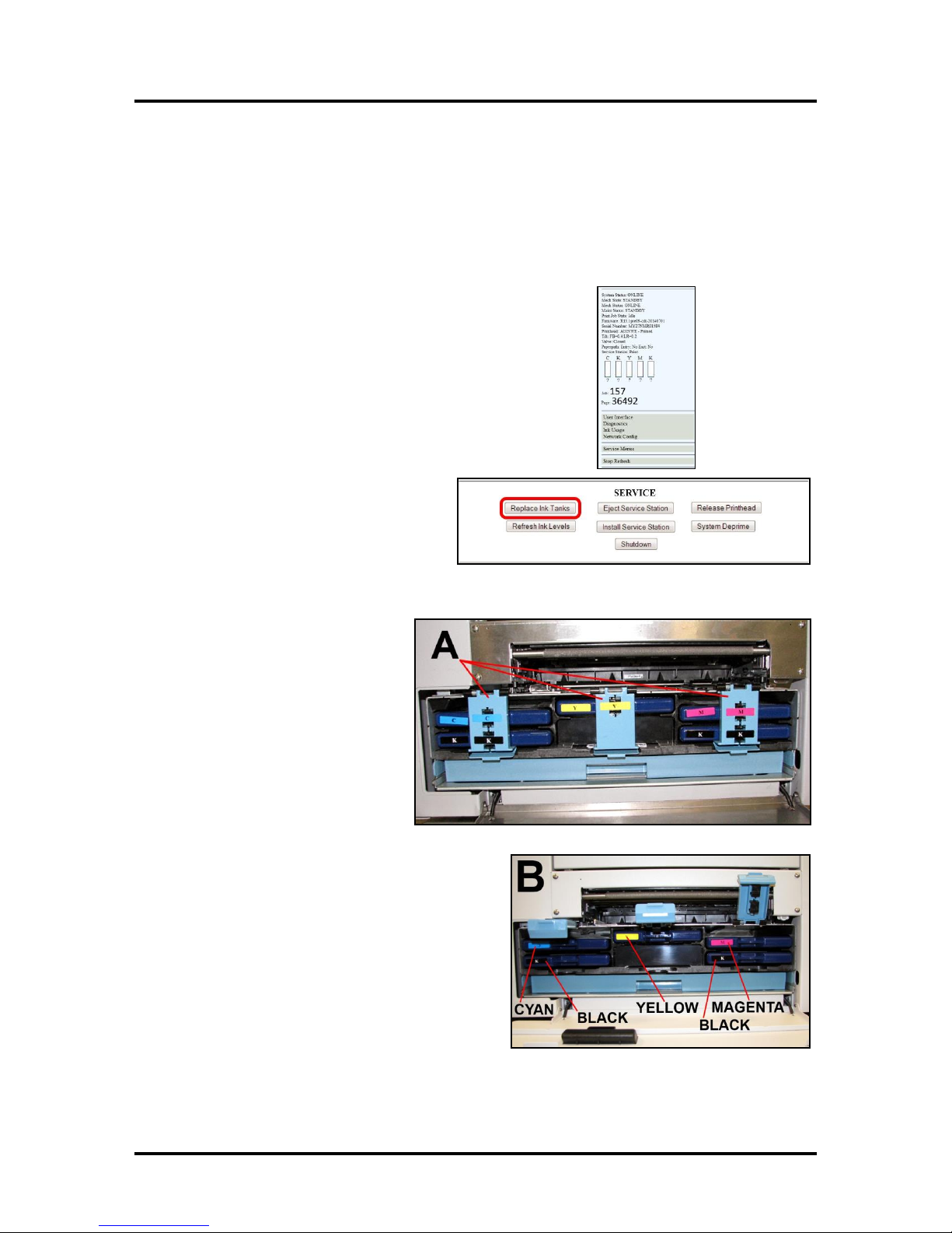
1. Open the Printer Toolbox. Go to the Start Menu and open
the “Toolbox”. You will see System Status information in the
upper left corner of the User Interface window. Note that
some or all of the “CKMYK” boxes may be low or empty.
2. Click “Replace Ink Tanks”. This disconnects Printer
communication with the Ink Tanks and allows safe
installation and replacement. Once the “Confirm” screen
displays, it is safe to remove the Ink Tanks.
IMPORTANT: DO NOT press
“Continue” until after you have
removed and replaced the Ink
Tank(s) and closed the Ink Tank
Latches.
3. Open the Front Cover (hinged at
bottom). Open the three Latches
[A] and pull the Ink Tank(s) out
of the Printer.
4. Remove the new Ink Tank(s)
from packaging.
5. Slide the new Ink Tanks (labels up) into their
appropriate color slots [B]. Close the three Ink
Tank Latches.
INSTALLATION TIP: Make sure the Ink
Tanks seat properly. Insert the Ink Tank
into the appropriate Ink Station, then pull
the Ink Tank back about an inch and push
forward firmly to insure that the Ink Nozzles
penetrate the seals on the Ink Tanks.
34
Page 39
WARNING!
The ink in the Ink Tanks may be harmful
if swallowed. Keep new and used Ink
Tanks out of reach of children. Discard
empty Ink Tanks immediately.
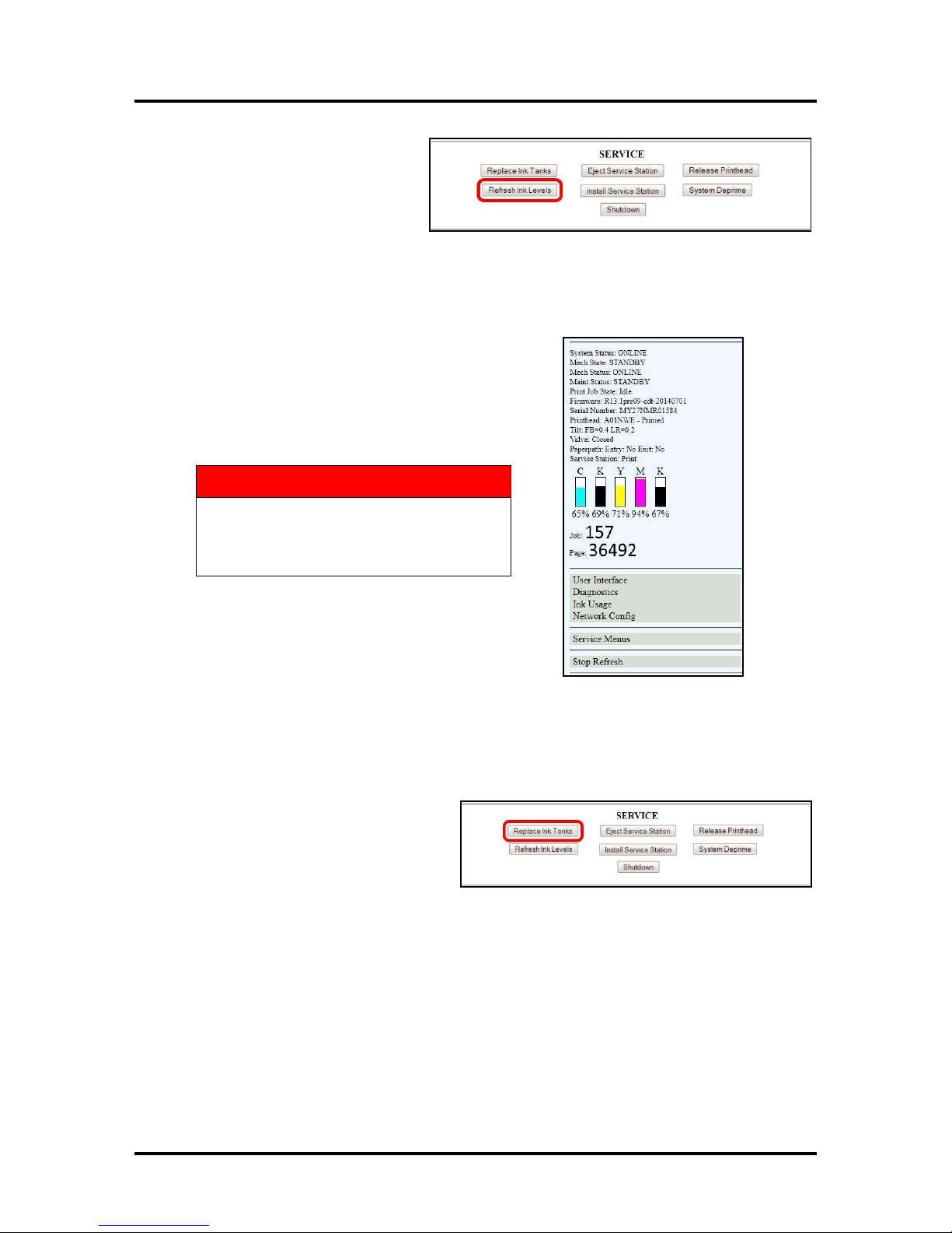
6. Click “Continue” on the Confirm
screen, then “Refresh Ink Levels”
on the User Interface screen. The
ink colors fill in as the Ink Tanks
are installed. If the ink colors do
not fill in after a few seconds, click
“Replace Ink Tanks” again and
reinstall the Ink Tank(s).
NOTE: If the Ink Tank is installed, but the Ink Tank indicator still does not refresh, see
“Cleaning Ink Tank Contacts” below.
7. When the Printer stops processing and all the fields in
System Status are black, the Printer is ready for use.
8. Close the Front Cover.
SECTION 4
MAINTENANCE
Cleaning Ink Tank Contacts
When reinstalling or replacing Ink Tanks, the Ink Level indicator in the Toolbox may not refresh. This may
be due to a dirty Ink Tank Level Prism and/or QA Chip contacts on that Ink Tank(s). You can clean the
contacts as follows:
1. Remove the Ink Tank(s). Open the
Toolbox. Click “Replace Ink Tanks”.
Once the “Confirm” window opens, it is
safe to remove the Ink Tanks.
IMPORTANT: DO NOT press
“Continue” until after you have
removed and replaced the Ink Tank(s) and closed the Ink Tank Latches.
35
Page 40
SECTION 4
MAINTENANCE
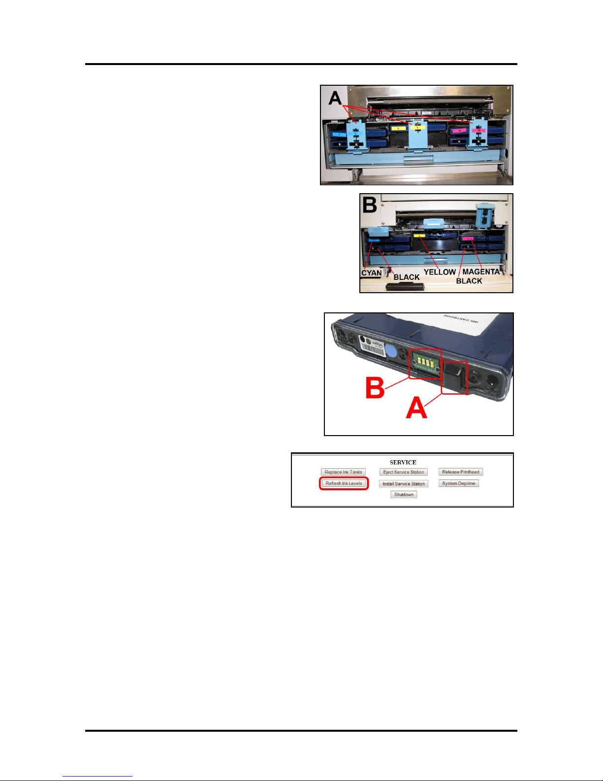
2. Open the Front Cover, release the Ink Tank
Latch(es) [A] and remove the Ink Tank(s) [B]
that did not refresh.
3. Clean the Ink Level Prism [A] and QA Chip
contacts [B] with a clean, dry, lint-free cloth.
NOTE: You can dampen the cloth with
distilled water to wipe the Prism, but
DO NOT get the QA Chip contacts wet.
4. Reinstall the Ink Tank(s) (labels up),
close the Ink Tank Latch(es). Click
“Continue” on the Confirm screen,
then “Refresh Ink Levels” on the User
Interface screen.
5. Close the Front Cover.
Storage
New Ink Tanks should be stored in their original packaging and kept away from heat.
Opened Ink Tanks should remain in the Printer.
Nominal Ink expiration date: 24 months following date of manufacture (ink fill date).
Disposal
The Ink Tank may be disposed of in a normal manner.
Clean up spills with soap and water. Abrasive soap is effective in cleaning ink off your hands.
36
Page 41
SECTION 4
CAUTION
Use electrostatic discharge (ESD) protection when handling.
Hold the Printhead Cartridge by the handles ONLY.
DO NOT touch the ink couplings, nozzle surface or electrical contacts.
DO NOT unpack the Printhead Cartridge until the Printer is ready for
installation. Once unwrapped, delay in installing the Printhead can
compromise print quality due to dehydration.
DO NOT place an unwrapped Printhead on any surface before
installing. Protect the Printhead from scratches, dust, fibers, dirt and
other contaminants at all times.
MAINTENANCE
Cleaning/Replacing the Printhead Cartridge
Cleaning
The Printhead in the Printer is cleaned automatically each time the machine is turned on or when the
“Quick Clean Printhead” routine is performed by the operator. This can be found under the Service Tab,
“Quick Clean Printhead” in the Printer Driver or the User Interface in the Printer Toolbox. “Normal
Clean Printhead” and “Full Clean Printhead” can be used to more thoroughly clean or clear the Printhead.
If running the automated Cleaning Levels doesn’t help improve print quality, the Printhead Cartridge can
be cleaned manually.
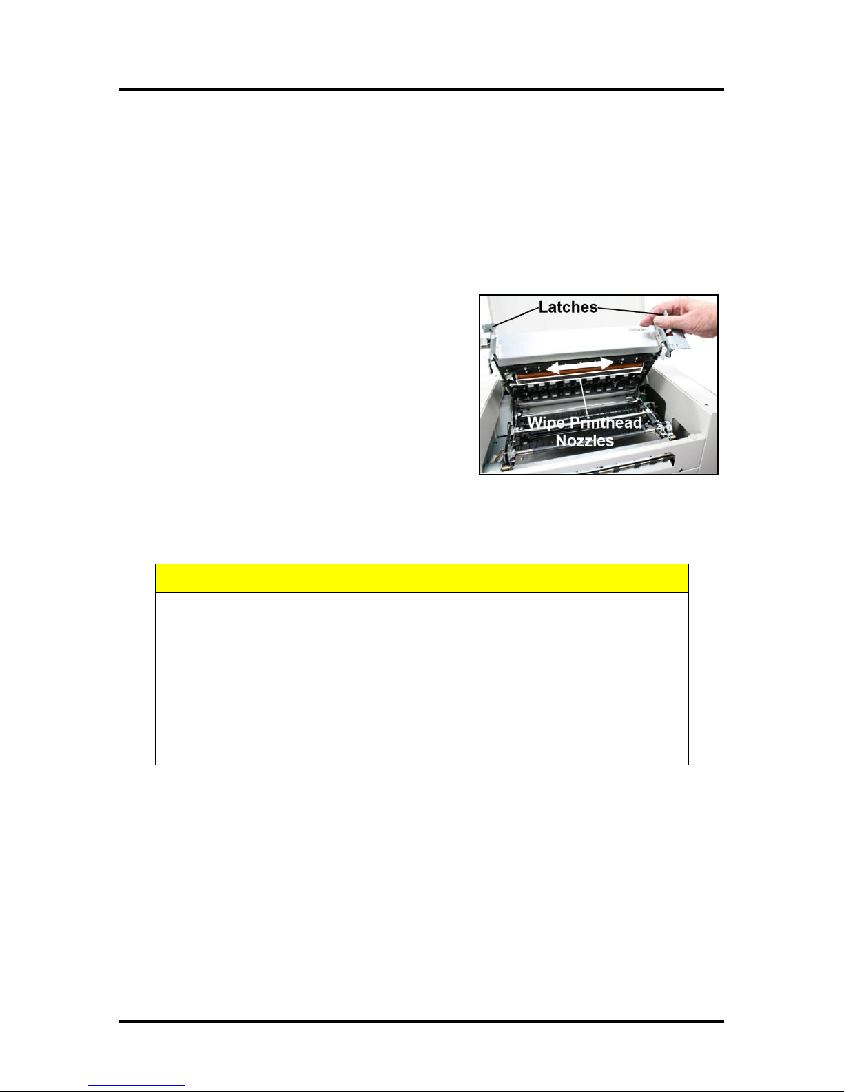
1. Open the Top Cover.
2. Release and lift the two latches (at the same time) to
raise the Print Engine Clamshell.
3. Moisten the Printhead nozzles using
deionized/distilled water (reference ASTM D5127-90
Type E-II Electronic Grade Water) and a damp, lint-
free cloth, wiping end to end. (Gray strip located
below orange strip.) Take care not to damage the
copper contacts, the metal plate, or the gold
Printhead surface.
4. Close and latch the Print Engine Clamshell.
Generally, when the ink supply is adequate and the print quality remains poor, or when the automated
cleaning processes or manually cleaning the Printhead has not helped the image quality, the Printhead
should be replaced.
37
Page 42
SECTION 4
CAUTION
DO NOT PRY OR MANUALLY LIFT THE
PRINTHEAD LATCH OR THE LATCH MAY
BREAK. ONLY OPEN THE LATCH USING
THE RELEASE BUTTON ON THE
PRINTER OR THE PRINTHEAD RELEASE
COMMAND IN THE PRINTER TOOLBOX.
MAINTENANCE
Replacing the Printhead Cartridge
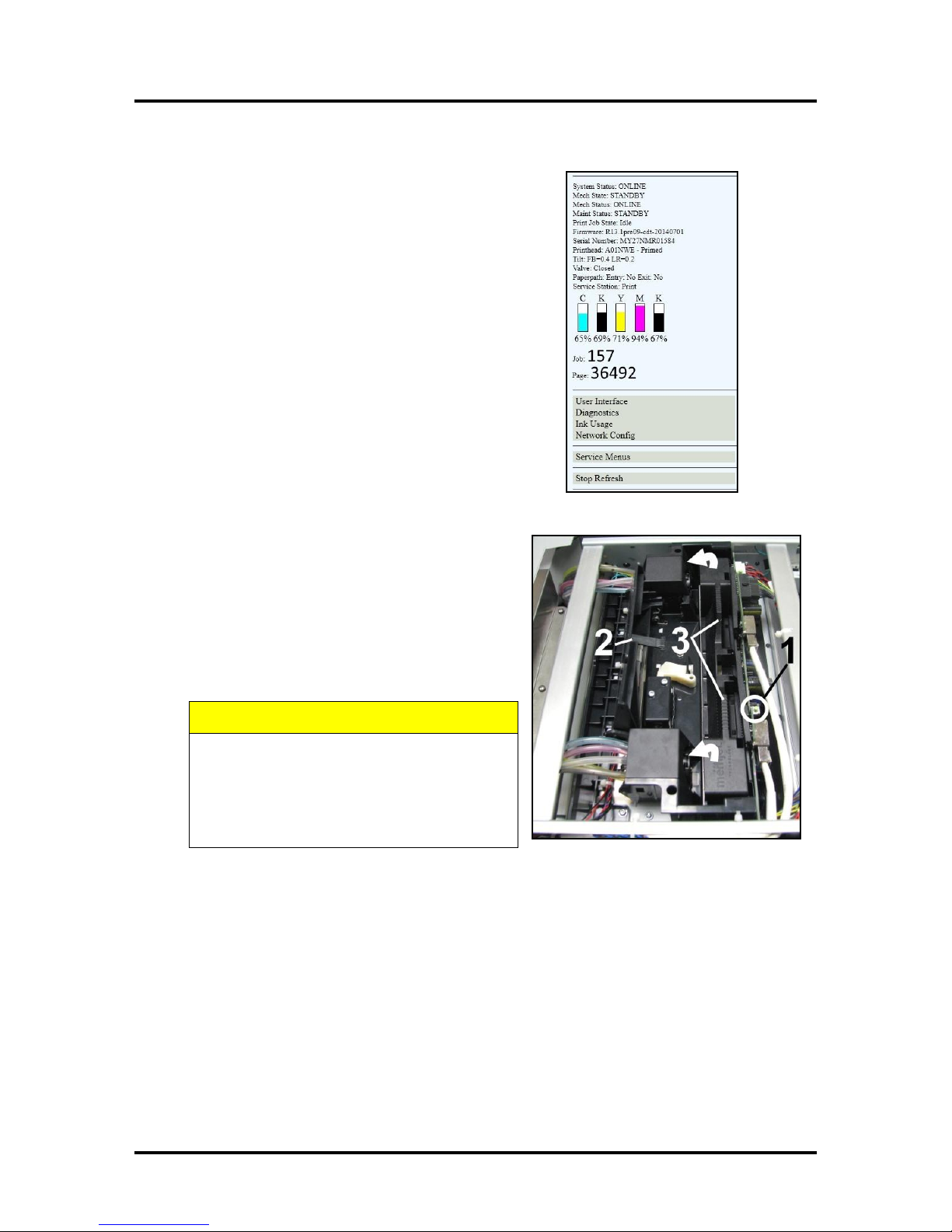
1. Open the Toolbox. On the User Interface screen
System Status information appears in the upper left
corner.
2. Open the Top Cover. Press the Printhead Latch
Release button [1]. The Printer pumps any ink in
the system back into the Tanks. Then the Printhead
Latch pops open [2].
NOTE: You can perform this same function
from your computer by clicking “Printhead
Release” on the User Interface screen in the
Printer Toolbox.
3. Make sure the Printhead Latch is fully opened to retract the ink lines. Remove the used Printhead
Cartridge by tilting it toward the ink lines [3], then carefully lifting it out of the Printhead
Compartment.
38
Page 43
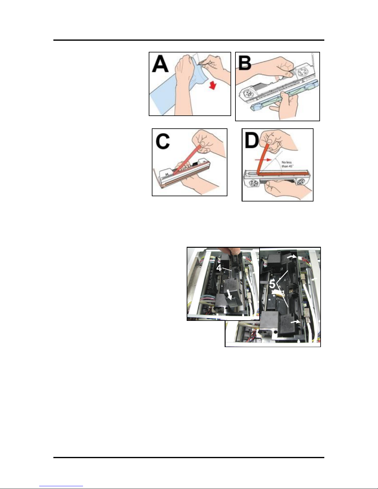
4. [A] Carefully remove
the Printhead Cartridge
from the foil packaging.
Tear at notch or cut end
with scissors.
[B] Remove the
protective plastic cover.
Hold the Printhead by the
handle and unclip the
cover from the Printhead.
[C] Remove protective
strip from the Printhead
electrical contacts.
DO NOT allow removed
strip to touch the
electrical contacts.
[D] Remove protective
strip from the Printhead
Nozzles. Hold the
Printhead by the handle. Pull the strip tab and slowly peel the
strip from the Printhead.
DO NOT pull the strip at less than a 45° angle from the Printhead surface.
DO NOT allow removed strip to touch the Printhead Nozzles.
NOTE: Keep foil packaging to store/dispose of old Printhead Cartridge.
SECTION 4
MAINTENANCE
5. Carefully insert the Cartridge into the
compartment at an angle [4], with the
Printhead surface facing down and the
Ink Nozzles facing the Ink Hoses. Once it
is seated, gently tilt the Cartridge back
until it snaps into an upright position [5].
DO NOT FORCE the Cartridge into
position.
39
Page 44
SECTION 4
CAUTION
HOLD ONTO BOTH LATCHES
WHEN OPENING AND CLOSING
THE PRINT ENGINE CLAMSHELL
TO PREVENT DAMAGE.
DO NOT ALLOW THE CLAMSHELL
TO DROP OR SLAM CLOSED.
TO PREVENT DAMAGE TO THE INK
LINES, A STOP LIMITS RAISING
THE CLAMSHELL MORE THAN 60°.
IMPORTANT!
CHECK INK TANKS. PRINTER MAY NOT FULLY
REPRIME IF TANKS ARE LESS THAN 1/3 FULL.
MAINTENANCE
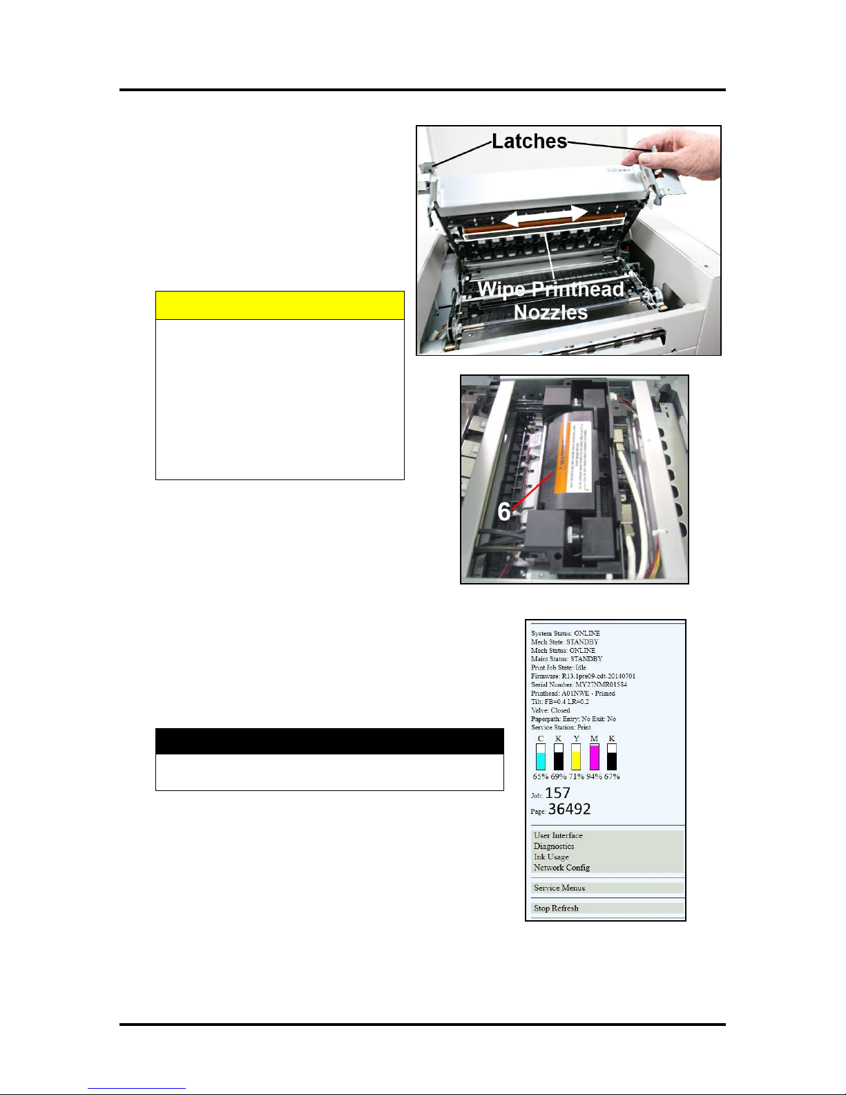
7. Wet the Printhead Surface. This
ensures that the Printhead will prime
correctly. Open the Top Cover. Release
and lift the two latches at the same time
to raise the Print Engine Clamshell.
Moisten the Printhead nozzles using
distilled water and a damp, lint-free
cloth, wiping end to end. (Gray strip
located below orange strip.) Close and
latch the Print Engine Clamshell.
8. Close the Printhead Latch [6]. The Printer
will start up and prime ink into the Printhead.
This may take a few minutes. Make sure that
ink is flowing through the hoses. If air bubbles
appear you may have to tap the lines or click
“Circulate Ink” in the Printer Toolbox to clear them.
9. Watch the Toolbox screen again. Notice that some of the
information is in red. As the Printer circulates ink and
primes the system these fields should all turn black.
10. When the Printer stops processing and all the fields in
System Status are black, the Printer is ready for use. Close
the Top Cover.
NOTE: The Printer may take up to 12 minutes to set itself up
during initial startup. This is normal.
40
Page 45
Storage Temperature Range:
Long Term: 14° F to 86° F (-10° C to 30° C)
Short Term: -11° F to 140° F (-25° C to 60° C)
NOTE: Cumulative storage duration above 86° F (30° C)
must not exceed 72 hours.
Humidity Range:
5% to 95% Relative Humidity, non-condensing
Atmospheric Pressure Range:
70 kPa to 106 kPa
Electrostatic Discharge:
8 kV air discharges or 4 kV contact discharges*
*When tested in accordance with IEC 61000-4-2
Printhead Storage
Store and transport the cartridge as indicated by the "this side up"
arrow symbol on the packaging.
The cartridge and ink supply must be within the operating
temperature range before attempting to prime the cartridge with ink
and starting to print. When stored at temperatures below the
operating range it may take up to 3 hours for a cartridge in its
packaging to reach operating temperature. NOTE: Additional
packaging will increase the time needed to reach operating temperature.
Storage Life: 12 months from date of manufacture (printed on shipping box).
SECTION 4
MAINTENANCE
Printhead Service Life
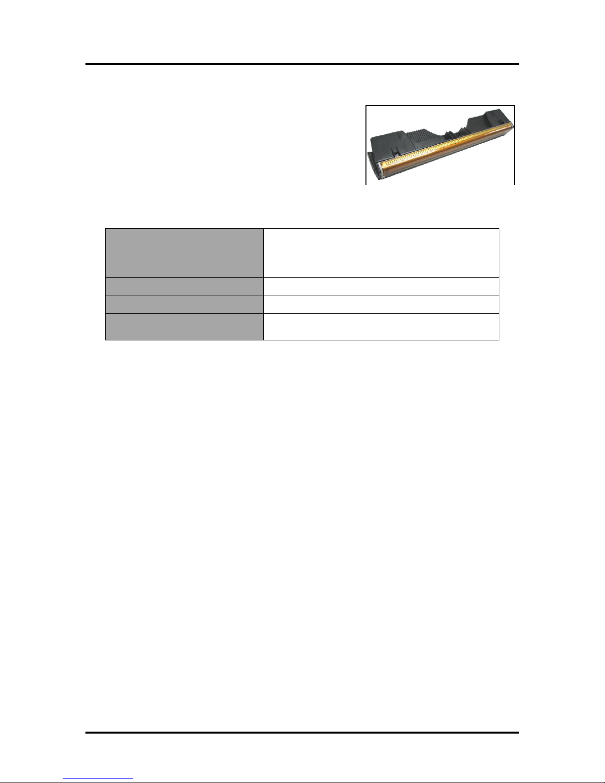
Projected: 50,000,000 ejections per nozzle. The Printhead has a total of 70,400 nozzles (14,080 per color
channel.) Since printing does not use the entire length of the Printhead, some nozzles do not fire as often.
The most often used Nozzles will degrade more quickly. Noticing the effects of failing nozzles depends
partly on the relative position of those nozzles to each other. In simple terms, the number of images printed
and the amount of ink that will pass through the printhead prior to printhead degradation will depend on the
make-up of the images printed, the operating environment, servicing, media characteristics (including
cleanliness) and other factors.
M-Series Printhead Return Policy
The following is the Return Policy and Return Procedure for Memjet Printheads for M-Series
Printers:
Limited Printhead Replacement Policy: M-Series Printheads are manufactured to be free from defects in
materials and workmanship. However, should an M-Series Printhead display an obvious defect or exhibit a
significant degradation of print quality prematurely, the Printhead may be returned for replacement.
Returns for these conditions can be made:
Up to 12 months after the shipping date from Astro Machine Corp. and
The Printhead's “Total pages printed” = 40,000 or fewer pages (at 15% page coverage), whichever
comes first.
This return policy excludes damage due to mishandling, tampering or misuse, improper storage or
transport, or material incompatibility*.
*See “Printhead Installation” and “Replacement” sections of this manual.
41
Page 46
SECTION 4
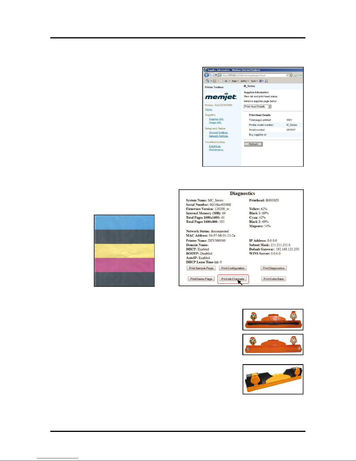
Ink Channels Printout
MAINTENANCE
Return Procedure:
1. Verify eligibility for return. Check the page count
printed by this Printhead, if the page total is more than
40,000 pages, the replacement policy does not apply.
NOTE: This is NOT the Printer page count.
Make sure the Printer is powered up and connected via
USB or network.
To check the Printhead Page count, enter one of the
following addresses in your URL search line (depending
on how your printer is connected):
[A] For printers connected via USB:
http://127.0.0.1:8080/view/supplies/printHead
[B] For printers connected via network:
http://type your IP address here/view/supplies/printHead
Print the page to include with your return.
2. Open the Printer Toolbox. Open the
Diagnostics page and click the Print Ink
Channels button.
3. Remove the Printhead Cartridge from the Printer per the Replacement
instructions found in the Operator's Manual.
4. Snap the Printhead back into in the orange plastic protective cover it was
shipped in. IMPORTANT! Make sure all foam pads that came with
the protective cover are installed and in place (two versions shown in
images at right).
5. Reseal the Printhead and Cover in a plastic bag (reuse and reseal the
original packaging if possible).
6. Place the Printhead, Printhead Page Count printout and Ink Channels
printout in a shipping box. Remember to include your company name,
contact information and return address as well.
7. Return to your Astro Machine distributor.
42
Page 47
SECTION 4
CAUTION
WHENEVER POWERING DOWN UNIT, ALWAYS:
1. PRESS THE POWER BUTTON ON THE CONTROL PANEL.
2. WAIT FOR THE PRINTER TO STOP PROCESSING.
3. THEN PRESS THE MAIN POWER SWITCH ON THE REAR PANEL.
MAINTENANCE
Replacing the Service Station
The Service Station (located above the Ink Tank Station) cleans the Printhead Cartridge of excess ink and
debris, keeps the Printhead hydrated and protected when not in use, captures ink used to keep nozzles clear,
and acts as a base to support media during printing. It is designed to provide a long service life. However,
should it need to be cleaned, serviced or replaced, follow these steps to remove it.
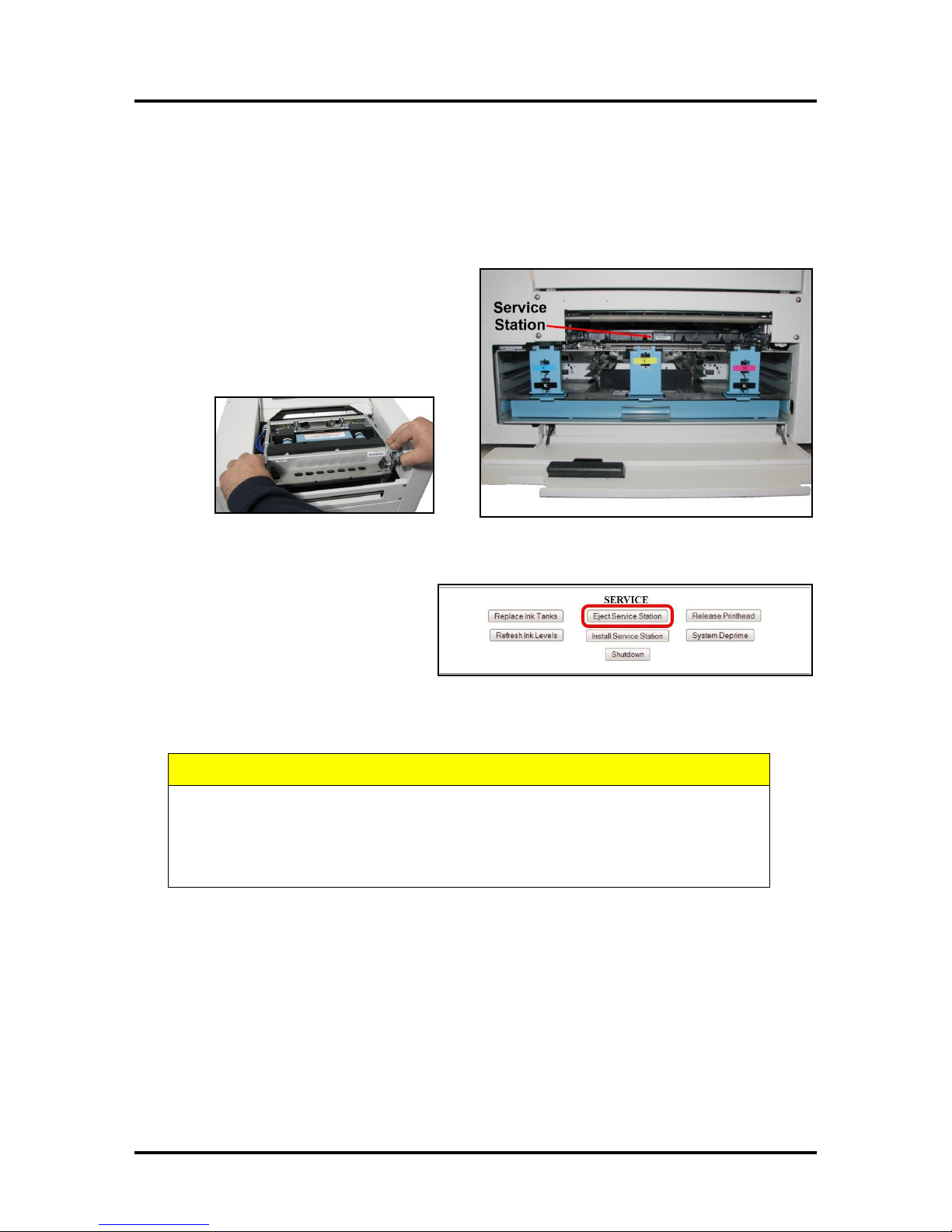
1. Open the Front Cover (hinged at
bottom). Open the Top Cover.
Release the two latches and open the
Print Engine Clamshell. The Service
Station will not fully eject with the
Clamshell closed.
2. Open the Printer Toolbox. Click
the “Eject Service Station” button.
Once the Printer pushes the Service
Station out, turn the Printer OFF.
TURN PRINTER POWER OFF.
43
Page 48

SECTION 4
CAUTION
MAKE SURE THE LATCHES ON
THE WIPER ROLLER ARE FULLY
LOCKED BEFORE INSTALLING
THE SERVICE STATION.
MAINTENANCE
3. Carefully slide the Service Station out of the Service
Station port. NOTE: DO NOT pull the Service
Station all the way out until you disconnect the
Ribbon Cable.
USEFUL TIP: Place an absorbent towel under the
Service Station before you remove it to catch any
drips or leaks.
4. Disconnect the Ribbon Cable. Slide the Latch open
on the Service Station Circuit Board to release the
Ribbon Cable. Remove the Service Station.
5. Carefully unwrap the new Service Station.
NOTE: Loose parts may fall out. Keep
the roller side facing up when removing
packaging.
44
Page 49
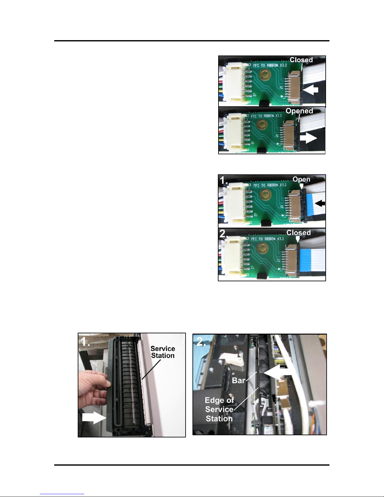
6. Slide the Latch open on the Service Station
Circuit Board.
7. [1] Plug the Ribbon Connector (blue side up) into
the space under the Latch.
[2] Close the Latch.
SECTION 4
MAINTENANCE
8. [1] Slide the Service Station into the Service Station port until it touches the bar. Align with tracks
along sides and Guide on Service Station dock floor.
[2] Look down through the Top Cover to make sure Service Station is aligned with the bar.
IMPORTANT! Service Station must be perfectly aligned with bar to prevent misalignment
and operating problems.
45
Page 50
SECTION 4
CAUTION
HOLD ONTO BOTH LATCHES WHEN
OPENING AND CLOSING THE
CLAMSHELL TO PREVENT DAMAGE.
DO NOT ALLOW THE CLAMSHELL
TO DROP OR SLAM CLOSED.
MAINTENANCE
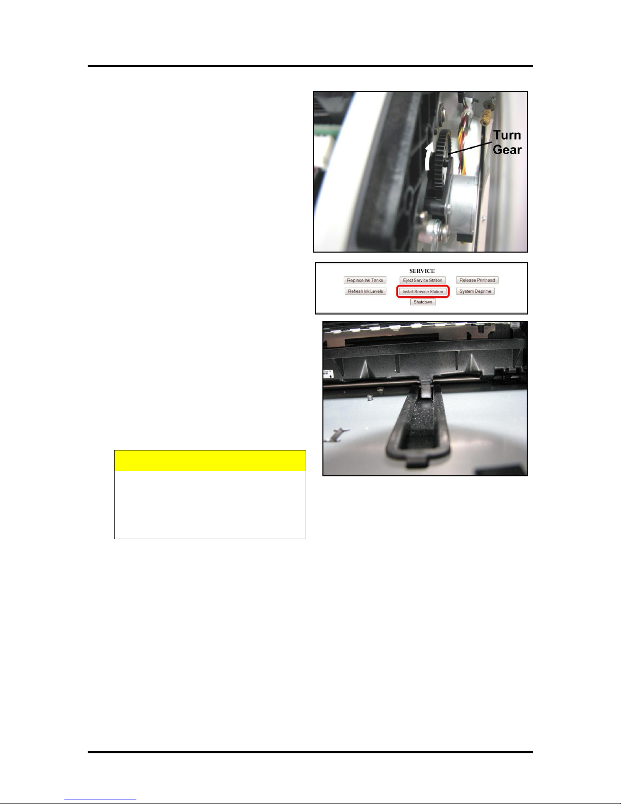
9. GENTLY push the Service Station while
turning the large Gear on right side of Print
Engine clockwise. Gear should engage
gear on Service Station Roller and pull it
in. Once the Service Station starts moving,
stop turning the gear.
10. Power up the unit, then click “Install
Service Station” in the Printer Toolbox to
pull the Service Station in.
NOTE: Make sure the wick hanging below
the Service Station is inside the plastic trough
inside the Ink Tank Station to prevent ink
seepage.
NOTE: Service Station should operate
smoothly. If it binds, chatters or grinds,
reinstall the Service Station. Lubricate Side
Tracks and Guide if necessary.
11. Close the Clamshell Cover. Close the
Front Cover.
46
Page 51
SECTION 4
MAINTENANCE
Replacing the Ink Waste Tray
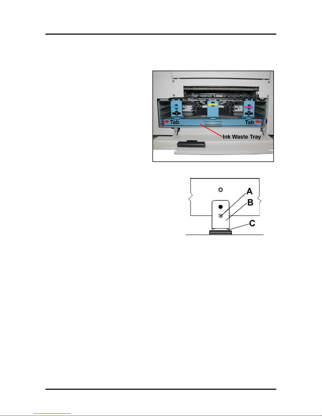
The Ink Waste Tray soaks up any excess ink that may drip from the Print Engine during operation. After a
period of time it may become saturated and need replacement.
1. Open Ink Tank Door.
2. Push in on the Tabs to release the Ink
Waste Tray and remove it from unit.
3. Replace with a new Ink Waste Tray.
Replacing the Sheet Separators
The Sheet Separators insure separation of the pieces as they are
being fed. If you experience double sheet feeding and cannot
adjust the Separators to prevent it, replace the Separators.
Replacing the Sheet Separators is not difficult:
1. Turn the Printer OFF and unplug it and from the power
source.
2. Release the Separator by loosening the Locking Knob
and moving the Paper Side Guides to their maximum
opened position.
3. Lower the Separators so that they touch the Feed Roller.
4. Remove the screw [A] and the Separator Cover [B]. Then remove the Separator [C] by prying it
out of the Holder.
5. Install a new Separator and replace the Separator Support and screw. DO NOT over-tighten the
screw to prevent distorting or damaging the Separator.
47
Page 52
SECTION 4
CAUTION
DO NOT BEND, PINCH OR CUT THE INK LINES LOCATED
DIRECTLY IN FRONT OF THE BRUSH ASSEMBLY.
CAUTION
HOLD ONTO BOTH LATCHES WHEN
OPENING AND CLOSING THE PRINT ENGINE
CLAMSHELL TO PREVENT DAMAGE.
DO NOT ALLOW THE CLAMSHELL TO DROP
OR SLAM CLOSED.
TO PREVENT DAMAGE TO THE INK LINES, A
STOP LIMITS RAISING THE CLAMSHELL
MORE THAN 60°.
B
Raise the Print Engine Clamshell
C
Unlatch the Print Engine Clamshell
B
MAINTENANCE
Jams in the Printer
If a jam occurs, STOP the Printer. Some possible causes for jamming are:
1. Feeding more than one piece of media (double-feeding).
2. Damaged media, such as dog-eared (turned down corners).
3. Media that is not stiff enough may not be usable. Media that meets Postal stiffness requirements
for automated feeding is acceptable in the Printer
4. Envelopes caught under the flap of another envelope or stick to one another.
Removing Jammed Media
Clearing a jam depends on where the jam occurred.
Feed Section: Clear by pulling the paper out of the Separators.
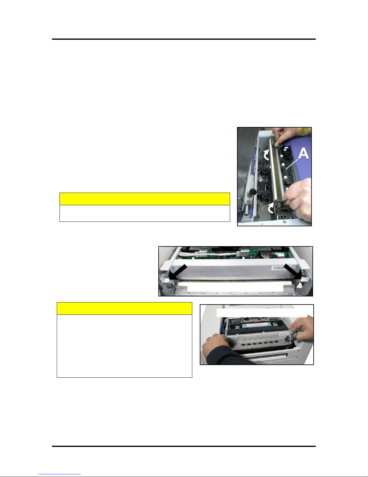
Antistatic Brush Assembly: If necessary, remove the Antistatic Brush
Assembly [A] to access jammed material. Unlatch the two latches (one
on either side of the Assembly) and lift the Assembly off the four
mounting pins as shown. Do not bend the brushes! Clear the jam, then
carefully reinstall the Brush Assembly.
NOTE: Make sure Brush Assembly is correctly reinstalled and
aligned before starting to print. Assembly should sit flat on transport area surface.
Print Engine Area: Open the Top
Cover. Release and lift the two latches
[B] (one on each side of the Print
Engine Clamshell) at the same time to
raise the Clamshell [C]. Clear the jam,
then carefully lower and relatch the
Clamshell. Close the Top Cover.
Misfeeds
Misfeeds can be corrected by readjusting the Sheet Separators to the media or replacing them. See
“Replacing the Sheet Separators” on previous page.
48
Page 53
SECTION 4
WARNING!
THE PRINTER IS A PRECISION MACHINE. CLEAN REGULARLY TO INSURE
MANY YEARS OF SERVICE. BEFORE PERFORMING ANY MAINTENANCE,
DISCONNECT THE MACHINE FROM ITS POWER SOURCE!
DO NOT REMOVE SIDE COVERS! HIGH VOLTAGES PRESENT.
CAUTION
NEVER SPRAY OR POUR CLEANERS DIRECTLY ON OR INTO THE PRINTER.
EXCESS LIQUID COULD HARM ELECTRONIC PARTS. DAMPEN A LINT-FREE
CLOTH WITH THE CLEANER AND APPLY IT TO THE PARTS TO BE CLEANED.
MAINTENANCE
Cleaning
Clean the Printer regularly to remove accumulated paper dust and ink. Depending on the types of media
that are run, paper dust may accumulate inside the Printer and on the Transport.
1. Turn the Printer OFF and unplug it from the power receptacle. Then open or remove the Covers.
2. Interior: Use a vacuum with a soft brush attachment or a can of compressed air to help loosen
dust particles. NOTE: Be careful around ink tray and capping station in the Print Engine area
as accumulated ink may splash onto other parts of the Printer. Take care not to damage the PC
Boards or electrical wiring.
3. Exterior: Wipe clean with a lint-free cloth using any standard nonabrasive household cleaner that
does not contain plastic-harming solvents.
Feed Rollers and Forwarding Rollers
The Feed and Forwarding Rollers can become glazed with paper lint and ink from the media. They should
be regularly cleaned with a mild abrasive household cleaner on a damp lint-free cloth.
NOTE: Avoid using solvents on the Rubber Rollers.
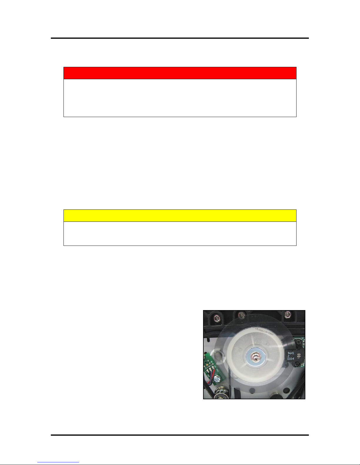
Encoder Wheel
If your machine has this type of Encoder Wheel in the Print
Engine Area (see picture at right), excess ink spray or
splashes may accumulate on the disk. This may disable the
Printer and issue a “DATA_PATH_UNDERRUN” error in
the Toolbox. It is necessary to wipe off any excess ink spray
or splashes to continue optimum performance.
Clean with distilled water on a damp, lint-free cloth by
grasping the wheel lightly with the cloth and turning the
shaft. Take care not to damage the Encoder Wheel.
49
Page 54
SECTION 4
CAUTION
USE ONLY DEIONIZED/DISTILLED WATER TO CLEAN PRINT ENGINE
COMPONENTS. AVOID CONTAMINATING THE PRINTHEAD WITH CLEANERS,
LUBRICANTS OR OTHER CHEMICALS.
MAINTENANCE
Print Engine
Areas in the Print Engine can become glazed with a buildup of dust, paper lint and accumulated ink and
have to be cleaned regularly. Open the Top Cover. Open the Clamshell Assembly by releasing the two
latches. Use a vacuum to pick up any loose debris.
NOTE: Be careful around Ink Tray and Capping Station in the Print Engine area as accumulated ink may
splash onto other parts of the Printer. Take care not to damage the PC Boards or electrical wiring.
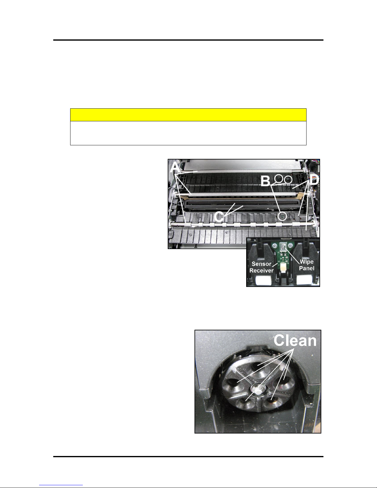
[A] Grit Rollers: Clean as needed by
moistening a small hard-bristled brush
or toothbrush with distilled water. DO
NOT use anything other than distilled
water to clean the Rollers.
[B] Media Sensors: Paper lint and
dust may build up on the Media
Sensors. Use a can of compressed air
or a damp (not wet) foam or lint-free
cotton swab to gently swab the
Sensors. Take care not to drip water
into the Circuit Boards. Use a clean,
dry swab to dab surfaces dry.
Remember to wipe the clear panel over the Sensor Receiver in the
upper Printhead Assembly (see inset).
[C] Capping Station Seal and Squeegee. Clean as needed with
distilled water on a damp, lint-free cloth. Be careful not to splash or
drip ink on other parts of the Printer.
[D] Printing Platen. Wipe with distilled water on a damp, lint-free cloth. Pat dry with a lint-free cloth.
Cleaning the Ink Revolver Couplings
1. First Deprime the system and remove the
Printhead Cartridge.
2. Moisten a foam swab in distilled water.
3. Insert the swab into one of the ink channels
and rotate the swab to clean the chamber.
4. Use a new swab for each of the remaining
ink channels until all 10 openings are clean.
(5 on each side.)
50
Page 55
SECTION 4
CAUTION
DO NOT PRY OR MANUALLY LIFT THE
PRINTHEAD LATCH OR THE LATCH MAY
BREAK. ONLY OPEN THE LATCH USING THE
RELEASE BUTTON ON THE PRINTER OR THE
PRINTHEAD RELEASE COMMAND IN THE
PRINTER TOOLBOX.
MAINTENANCE
Shipping or Transporting the Printer
If you have to ship or transport the Printer for any reason, the unit will have to be prepared. Once the
Printer is prepared, carefully package the Printer, Printhead Cartridge, Service Station and Ink Tanks in
their original packaging.
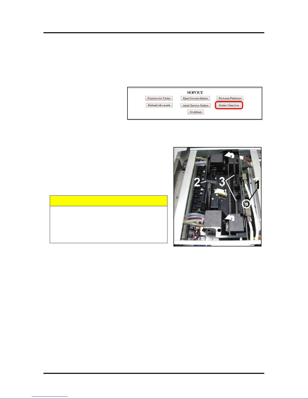
Deprime the System
1. Depriming forces all of the
ink to return to the Ink
Tanks. Open the Toolbox
User Interface screen and
click “System Deprime”.
Remove the Printhead Cartridge
1. Open the Top Cover. Press the Printhead Latch
Release Button [1]. The Printer pumps any ink in
the system back into the Tanks. Then the Printhead
Latch pops open [2].
NOTE: You can perform this same function
from your computer by clicking the “Printhead
Release” on the User Interface screen in the
Printer Toolbox.
2. Make sure the Printhead Latch is fully opened to retract the ink lines. Remove the Printhead
Cartridge by tilting it toward the ink lines [3], then carefully lift it out of the Printhead
Compartment.
3. Pack the Printhead Cartridge area with absorbent towels to catch any ink drips or spills. Carefully
pack the Cartridge using the original packaging.
51
Page 56
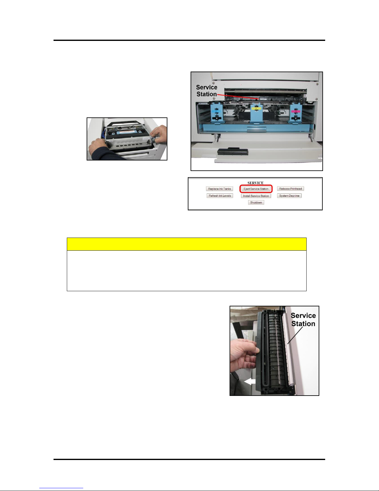
SECTION 4
CAUTION
WHENEVER POWERING DOWN UNIT, ALWAYS:
1. PRESS THE POWER BUTTON ON THE CONTROL PANEL.
2. WAIT FOR THE PRINTER TO STOP PROCESSING.
3. THEN PRESS THE MAIN POWER SWITCH ON THE REAR PANEL.
MAINTENANCE
Remove the Service Station
1. Open the Front Cover (hinged at
bottom). Open the Top Cover.
Release the two latches and open the Print
Engine Clamshell. The Service Station will
not fully eject with the Clamshell closed.
2. Open the Printer Toolbox. Click “Eject
Service Station”. Once the Printer
pushes the Service Station out, turn the
Printer OFF.
TURN PRINTER POWER OFF.
3. Carefully slide the Service Station out of the Service
Station port. NOTE: Do not pull Service Station all the
way out until you disconnect the Ribbon Cable.
NOTE: Place an absorbent towel under the Service
Station before you remove it to catch any drips or leaks.
52
Page 57
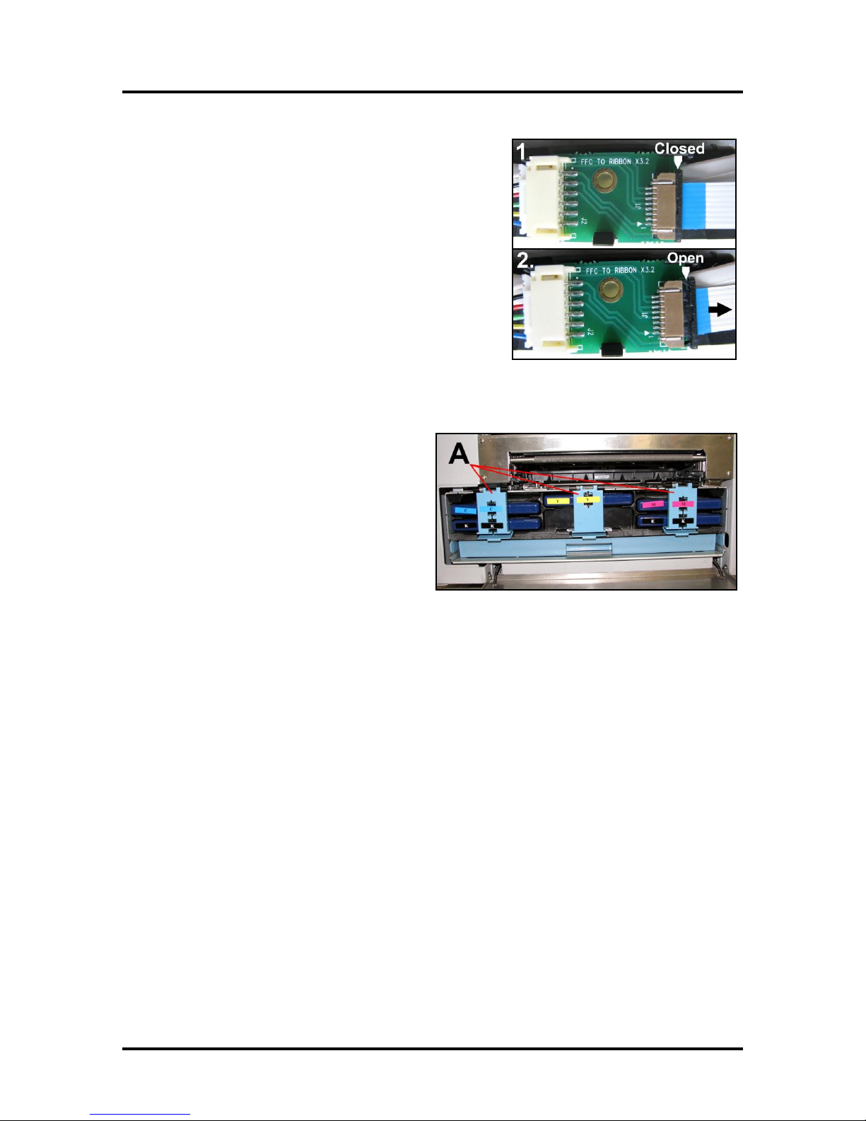
4. Disconnect the Ribbon Cable. Slide the Latch open on
the Service Station Circuit Board to release the Ribbon
Cable. Remove the Service Station.
Remove the Ink Tanks
1. Open the Front Cover (hinged at bottom).
Unlatch the three Locks [A] and pull the
Ink Tank(s) out of the Printer.
SECTION 4
MAINTENANCE
2. Carefully package the Ink Tanks in the
original packaging.
IMPORTANT: Make sure the ink seals
on the Ink Tanks are facing up to prevent
leakage.
3. Pack the Ink Tank bays with absorbent towels to catch any ink drips or spills.
53
Page 58
SECTION 5
CONDITION
PROBLEM
SOLUTION
Missing parts of letters or
text.
Air and bubbles blocking Nozzles.
Clean the Printhead using
recirculation, priming or
cycles of depriming and
priming found in the Driver or
Toolbox.
Rehydrate the Printhead
using distilled water and a
wet, clean, lint-free cloth.
Bubbles often disappear with
Printer use.
Print shows regularly
missing or misdirected
nozzles or ink color mixing.
Debris on Printhead.
Perform the startup routine.
Clean the Printhead using
one of the Cleaning Levels in
the Driver or Toolbox.
Wipe the Printhead manually
with distilled water and a wet,
clean, lint-free cloth.
Replace the Printhead.
Ink mixing – Mixed or muddy
colors.
Causes: Ink flooding, air in the
Printhead or a dirty Printhead.
Clean the Printhead using
one of the Cleaning Levels in
the Driver or Toolbox.
Wipe the Printhead manually
with distilled water and a wet,
clean, lint-free cloth.
No print or crisp blocks of
missing drops.
Electrical failure or poor electrical
connection.
Reseat the Printhead.
Replace the Printhead.
System will not reprime ink
after replacing Printhead
Cartridge
Printhead nozzles dry.
Ink Tanks may be 1/3 full or less.
Wipe the Printhead manually
with distilled water and a wet,
clean, lint-free cloth.
Replace Ink Tanks.
WARNING!
DO NOT REMOVE THE SIDE COVERS OF THE PRINTER!
THERE ARE HIGH VOLTAGES PRESENT BEHIND THE COVERS!
TROUBLESHOOTING
SECTION 5 – Troubleshooting Guide
The following Troubleshooting Guides are provided to assist you in solving any problems that might occur
with the Printer. We have tried to make them as complete as possible. The best advice we can offer is to
make sure that the system is set up properly, plugged in, and that it has an adequate supply of ink before
attempting to troubleshoot any problem.
The Memjet® Printhead
54
Page 59
CONDITION
PROBLEM
SOLUTION
Ink Tank installed, no Ink
Level indication in Toolbox
Ink Tank contacts dirty,
preventing Printer/Ink Tank
communication.
Remove Ink Tank(s). Clean prism
and QA Chip contacts, see
Maintenance, Cleaning Ink Tank
Contacts.
Extra lines; losing data
Database problem.
Check data in database program.
Improper output
(address information out of
order, misfeeding, etc.)
Wrong interface settings.
Static electricity.
Dirty Media Sensor.
Check software or database on PC.
Close the software, then turn Printer
OFF and ON.
Clean Media Sensor.
Media jams
Double feeding.
Media is curled or bent.
Media is too thin.
Adjust Sheet Separators on Feeder.
Uncurl media.
Minimum thickness for media is
0.004".
No communication
Improper cabling / connector.
Unit not receiving power.
Use proper USB cable
(see Operator Manual.)
Check plug connections, ON/OFF
button and fuse on back panel.
Print too light or missing
character dots
Clogged or dirty Printhead.
Running out of ink.
Check the Printhead.
Check Ink Tanks.
Blurry address
Image is not sharp.
Clean Printhead using one of the
Cleaning Levels in the Driver or
Toolbox.
Clean the Printhead manually using
distilled water and a wet, clean, lintfree cloth.
Feeding problems
Double sheets.
Misfeeds.
Adjust the Sheet Separators.
Job is sent to print but does
not print.
Printer not turned ON.
Printer not connected to
computer.
Media Sensor is covered in
Print Engine.
Check that Printer is ON.
Connect printer cable to computer
and resend the job.
Open Print Engine and remove
media.
The Printer
SECTION 5
TROUBLESHOOTING
55
Page 60
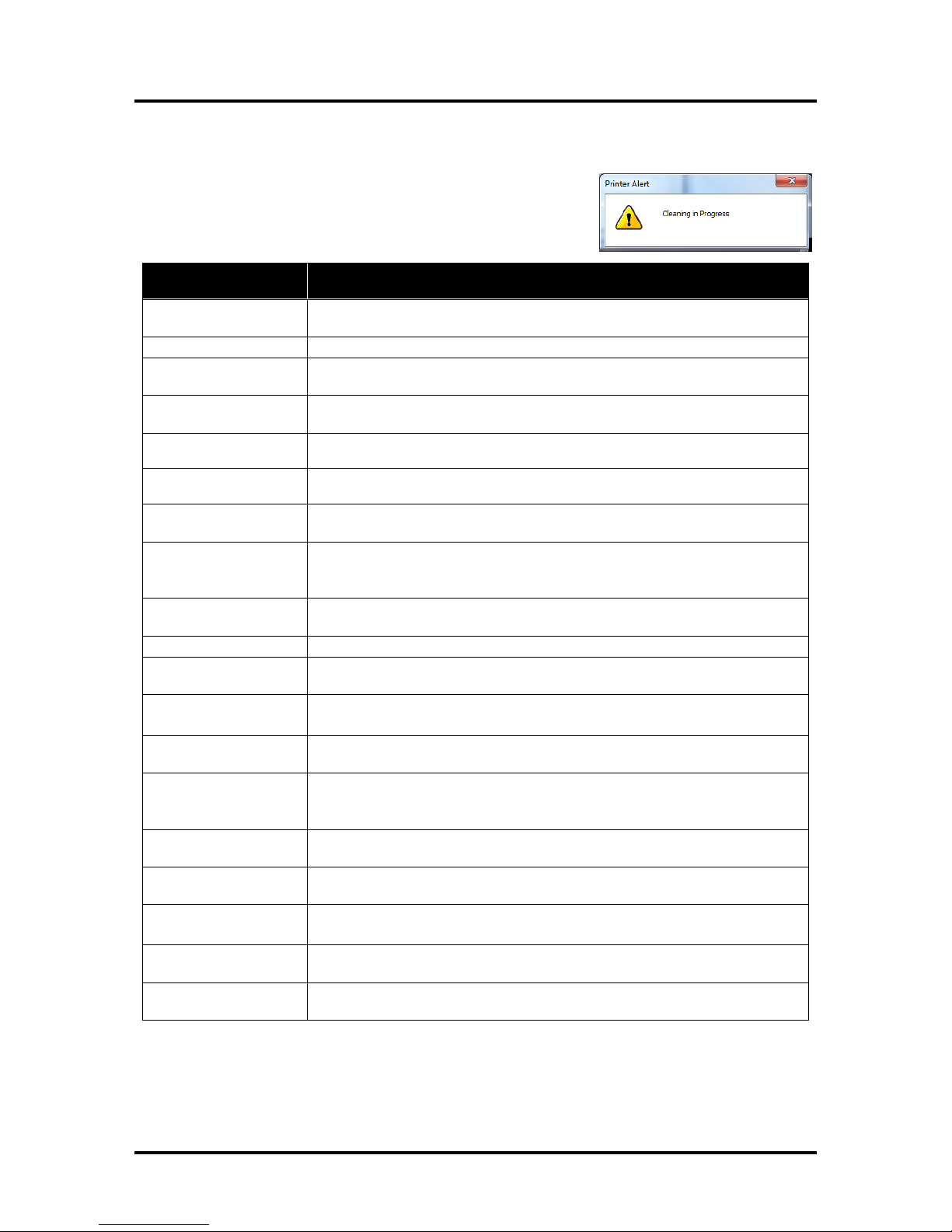
SECTION 5
MESSAGE
SOLUTION
Cleaning in Progress
Wait until the message disappears. The Printer will start printing your job once
the cleaning process is complete.
Excessive Tilt Error
See details under “Toolbox System Status Messages” section.
Incompatible
Printhead
Remove and reinsert your Printhead Cartridge. Replace Printhead. Printhead
Cartridges must be purchased from authorized supplier for this printer model.
Incorrect … Ink Tank
Replace Ink Tank. Ink Tanks must be purchased from authorized supplier for
this printer model.
…. Ink Low
Example: Black Ink Low
Reorder Ink.
…. Out of Ink
Example: Cyan Ink Out
Replace empty Ink Tank.
Load Paper
Out of Paper. Load paper into the Printer and press the PAPER button to
resume printing.
Mechanical Jam
Check for and remove the obstruction, then press the PAPER button to
resume printing.
Check/Clean Sensors. If problem persists contact technical support.
Missing Printhead
Remove Printhead Cartridge. Check/clean electrical contacts. Reinsert
Printhead. Replace Printhead. If problem persists contact technical support.
Multiple Inks Low
Reorder Ink.
Multiple Ink Tanks
Out
Replace empty Ink Tanks.
Multiple Ink Tanks are
missing
Insert missing Ink Tanks.
Clean electrical contacts and reseat Ink Tanks.
Multiple Unauthorized
Ink Tanks
Remove and reinsert Ink Tank. Replace Ink Tank. Ink Tanks must be
purchased from authorized supplier for this printer model.
Paper Jam
Remove jammed media. Check for proper feed setup then press the PAPER
button to resume printing.
Check/Clean Sensors. If problem persists contact technical support.
Printhead Latch Open
Ensure that Printhead Cartridge has been inserted properly then close the
Printhead Latch so it locks.
Print Zone Assembly
(Clamshell) Open
Check to be sure the Clamshell is completely closed and latched. Make sure
Print Engine Latches are secure.
The … Ink Tank is
missing
Insert missing Ink Tank.
Clean electrical contacts and reseat Ink Tank.
Unauthorized … Ink
Tank Installed
Ink Tanks must be purchased from authorized supplier for this printer model.
Unauthorized
Printhead
Printhead Cartridges must be purchased from authorized supplier for this
printer model.
TROUBLESHOOTING
Errors and Warnings
Printer Alert Window Messages
Messages sent from the driver and displayed on PC screen in a small
popup window.
56
Page 61
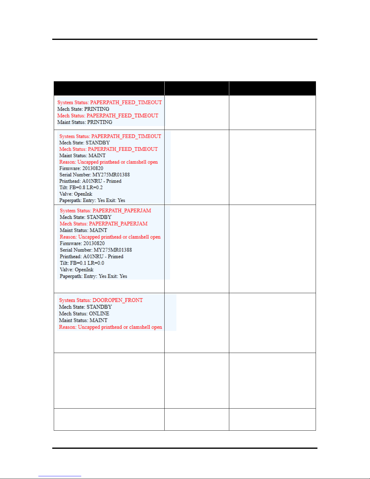
SYSTEM STATUS
SOURCE
SOLUTION
Out of Paper
Media is not reaching
the Print Engine.
Hesitation in media
feed.
Load media into Printer and
press the PAPER button to
resume printing.
If media is present; check/adjust
the Guides and Separators.
Paper Jam
When “Out of Paper”
error is shown in
combination with
“Uncapped Printhead”
or “Clamshell open”
error, a Paper Jam is
indicated.
See below
Paper/Media jam
detected.
Printer has detected
that one (or both) of the
media sensors are
blocked (interrupted).
Carefully remove jammed media
from Printer and close the Print
Engine. The System Status
message in red should go away.
The Toolbox “Paperpath” line
should change to:
Paperpath: Entry: No Exit: No
After jam is cleared, you can:
Press PAPER to resume
printing.
Press CANCEL to cancel the job
then manually clear the job from
the computer’s print queue.
Indicates that the
“Clamshell” is open.
Sensor cable
unplugged P202.
Verify that the Clamshell is
closed and securely latched on
both sides. Make sure that the
Clamshell switch (located on
opposite side) is activated by the
Clamshell Lever.
Use the Scan Sensors in the
Toolbox to check that Clamshell
switch is functioning.
DATA_PATH_UNDERRUN
Media is not moving
from the Entry Sensor
to the Exit Sensor
within a specified time.
Possible issue with
format or orientation of
job being sent.
Dirty Encoder Wheel.
Check/clean Transport Rollers.
Check/clean the Sensors.
Try changing the orientation
setting in the software/driver or
setting a different media size.
Check/clean the Encoder Wheel.
If problem persists contact
technical support.
INK _LOW
X = Color.
One or more Ink Tanks
are low on ink.
Ink Tank replacement will be
necessary soon. Reorder Ink.
Toolbox System Status Messages
Displayed in red in the M Series Toolbox utility.
(Valid for printers with firmware version 20130820 or higher installed.)
SECTION 5
TROUBLESHOOTING
57
Page 62
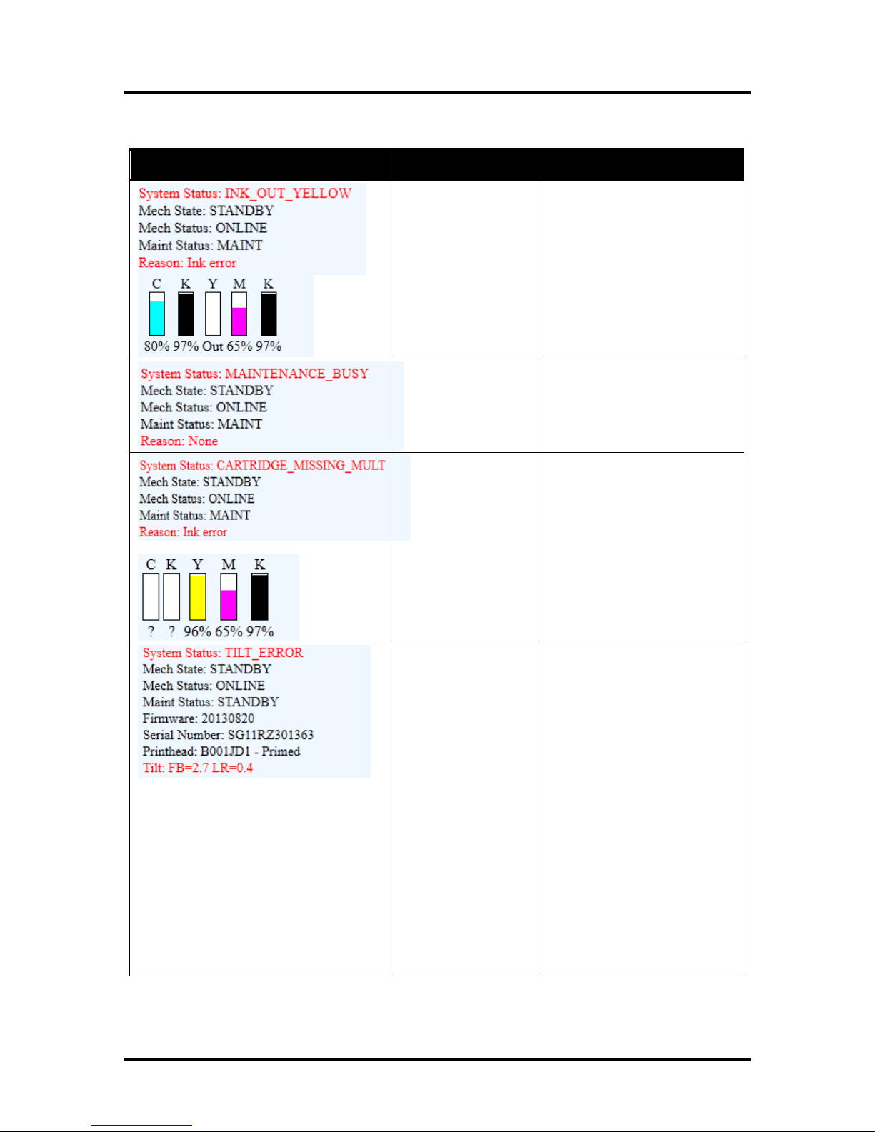
SECTION 5
SYSTEM STATUS
SOURCE
SOLUTION
X = Color.
One or more Ink
Tanks are out of ink.
Replace empty Ink Tank(s),
using the “Replace Ink Tanks”
command from EWS.
Verify that the Ink Tanks are
seated firmly and the latches are
fully closed.
Clear error using “Refresh Ink
Levels” command in the Toolbox
or just press PAPER to refresh
ink levels and continue printing.
Machine is performing
a maintenance
procedure.
No action required.
Ink Tank is missing or
not recognized
(obtained from an
unauthorized reseller).
If correct ink, check
contacts.
Insert missing Ink Tank or pop
the Ink Tank in and out to
improve connection.
Clear the error using the
“Refresh Ink Levels” command in
the Toolbox or just press PAPER
button to refresh ink levels and
continue printing.
Printer is not level*.
Printer’s electronics
have detected that the
Print Engine is too far
out of level.
Tilt Sensor needs to
be recalibrated.
P2005 unplugged.
*NOTE: Tilt should
be less than ±2
degrees. If Tilt
warning indicates
more than ±2
degrees FB or LR,
(even if Printer
continues to run)
Printer must be
leveled again to
prevent damage or
print issues.
Make sure that Printer is placed
on level surface. Failure to do so
may result in severe ink mixing
and cause an inaccurate ink
level reading in the Ink Tanks.
If just powered on, wait a few
minutes; the error may clear by
itself. Once the Tilt Level drops
to 1.99 or less you can clear the
error using the “Clear Error”
feature in the Toolbox.
Make sure Printer is placed on a
sturdy, level worktable. DO NOT
move Printer while power is on.
If the Tilt Level is 1.99 or less
you can clear this error using the
“Clear Error” feature in the M
Series Toolbox.
Contact technical support person
to have them check level and
possibly “Zero” the Tilt Sensor.
TROUBLESHOOTING
Toolbox System Status Messages (Continued)
58
Page 63
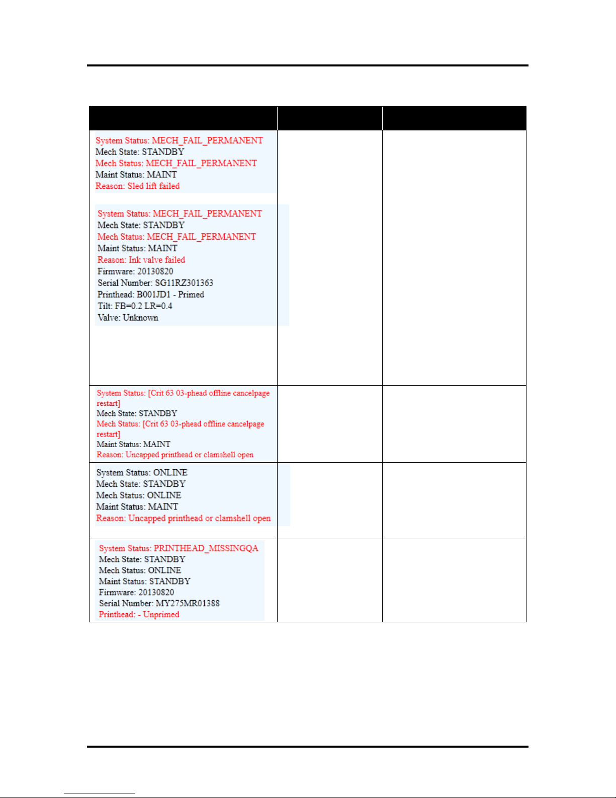
SYSTEM STATUS
SOURCE
SOLUTION
Mechanical error
One of the Printer's
mechanical
components was not
properly registered at
the expected position.
Mechanical failure or
Sensor failure.
Visually inspect the component
stated as a “Reason” for failure.
Using the Scan Sensors page in
the Toolbox, perform the toggle
test on the Sensor responsible
for registration of the failed
mechanical component position.
Lifter Arm Sensor is dirty or
damaged, Lifter Motor Cable is
unplugged, operator's side
Lifting Arm is damaged, or the
Lifting Arm mechanism is stuck.
Dual Pinch Valve problem:
Check Sensor board connector
and flag/sensors alignment.
Check Valve motor connector.
Check P2005 cable on MPCA.
At this point, this error may
represent an Ink Pump error,
since there is no return signal
from the pump and therefore, a
separate message describing an
Ink Pump error.
Data Cables
unplugged, dirty
Printhead contacts,
dirty PPCA contacts.
Check data cables (P250,
P260), clean Printhead contacts,
and/or clean PPCA contacts.
Service Station is
ejected, Service
Station position
sensors are damaged
or malfunctioning.
Check the Service Station
position. Using the Scan
Sensors page in the Toolbox,
perform the toggle test on the
two Sensors responsible for
registration of the Service
Station position.
Printhead missing and
one or more of the Ink
Tanks are missing,
When this error
occurs, Multiple EWS
monitoring is disabled.
Install Printhead.
Install Ink Tanks.
Toolbox System Status Messages (Continued)
SECTION 5
TROUBLESHOOTING
59
Page 64
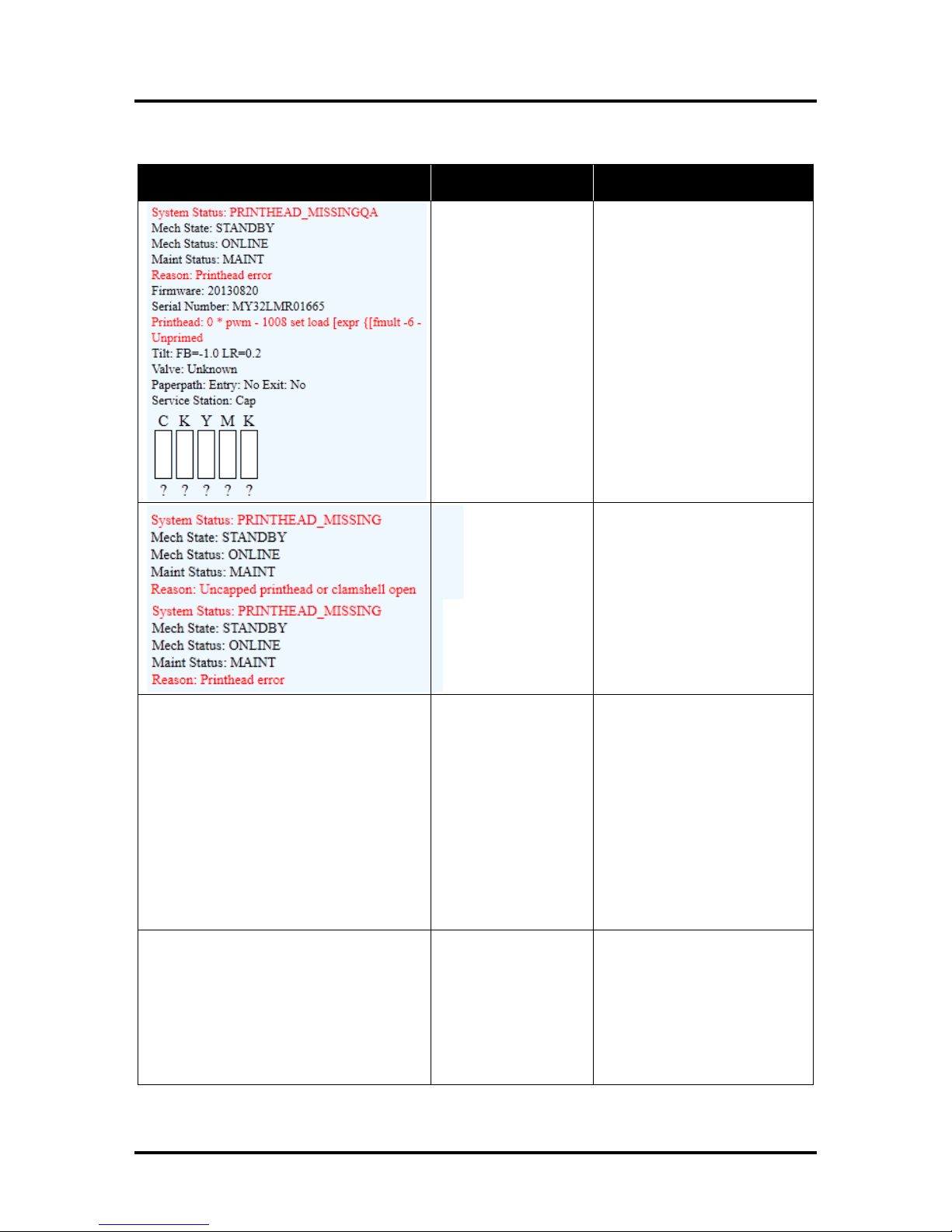
SECTION 5
SYSTEM STATUS
SOURCE
SOLUTION
Printhead missing and
one or more of the Ink
Tanks are missing.
When this error occurs,
Multiple EWS
monitoring is disabled.
Install Printhead.
Install Ink Tanks.
No Printhead installed
or Printhead not
making proper
connections.
J2001 cable
unplugged.
Printhead Latch is
open.
If the Printer was just powered
on, wait a minute; error may
clear by itself.
Install Printhead Cartridge.
Remove and reinstall Printhead.
Replace Printhead. Refer to the
appropriate sections in this
manual for removing and
installing Printhead Cartridge.
PRINTHEAD_UNPRIMED
Printhead priming
process has failed.
If Printer was just powered on,
wait a minute; error may clear
by itself.
Remove Printhead Cartridge,
wet the print nozzles using
deionized or distilled water and
reinstall the Printhead Cartridge.
Refer to the appropriate
sections in this manual for
removing and installing the
Printhead Cartridge. If you
continue to have trouble priming
the Printhead; check for kinked
or pinched color tubes.
MECH_CANCELPAGE
Job was cancelled by
user pressing the
CANCEL button.
Job was interrupted by
“Clamshell” being
momentarily opened.
Wait until print job has cleared
from Printer. Then manually
clear job from computer’s print
queue. Then send new print job.
Check to be sure “Clamshell” is
securely latched, and then press
“Clear Error” button to continue.
If problem persists contact
service support.
TROUBLESHOOTING
Toolbox System Status Messages (Continued)
60
Page 65
PRINT RESOLUTION
Best: 1600 x 1600 DPI
Normal: 1600 x 800 DPI
SPEED
(color or mono)
Up to 3600 letter size pages or 9000 envelopes per hour
MEDIA SIZE
Minimum: 3" x 4.2" (76 mm x 107 mm)
Maximum: 9.5" x 17" (241 mm x 431 mm)
PRINT AREA
8.5" x 30" (215 mm x 762 mm)
MEDIA THICKNESS
Minimum: 0.004" (0.102 mm)
Maximum: 0.020" (0.5 mm)
DUTY CYCLE
350,000 #10 Envelopes per month
INK
Water-based ink. 5 individual 250 ml ink tanks (CMYKK)
PRINT CARTRIDGE
Memjet® Replaceable Printhead
INTERFACE
USB 2.0 and Ethernet
ELECTRICAL
110 VAC, 50/60 Hz (220-240 VAC, 50/60 Hz available)
DIMENSIONS
20" W x 24" L x 17-1/4" H (50.8 cm x 61 cm x 44.0 cm)
WEIGHT
75 lbs. (34 kg)
SUPPLIES
Black Ink Tank
123-2412
Cyan Ink Tank
123-2413
Magenta Ink Tank
123-2414
Yellow Ink Tank
123-2415
OPTIONAL HARDWARE
Conveyor /Stacker
Conveyor Leg Kit
Conveyor Drop Tray
CD-700
57E-600-10
DTM-255
Drop Tray (Printer)
DT-420
Appendix A – AstroJet M1 Specifications
APPENDICES
All Specifications Subject To Change Without Notice
Appendix B – Supplies and Optional Hardware
The following supply items and optional hardware are available from your
Astro Machine Distributor:
61
Page 66

INDEX
#10 Envelope Setup 21
9.5" x 17" Paper Setup 21
A
Adjustable Media Guide 1, 2, 8
Assembling Printer 8
C
Cancel Button 1
Cartridge, Printhead 3
Choose Location 6
Clamshell Latches 3
Cleaning
Encoder Wheel 49
Ink Revolvers 50
Ink Tank Contacts 35
Print Engine 50
Printer 49
Printhead 37
Rollers 49
Connection
Computer 9
Network 2, 9
Printer 9
USB 2, 9, 11
Control Panel
Cancel Button 1
LED Chart Cutout 67
Paper Button 1
Power Button 1
Control Panel Button Functions 5
Counter, LCD 2
D
Diagnostics, Toolbox 30
Disposal, Ink Tanks 36
E
Encoder Wheel, Cleaning 49
Envelope Attachment Spacers 18
Envelope Printing Attachment 17
Envelope/Paper Media Guide 1, 2
Envelope/Paper Side Guide 8
Error Messages 56
F
Feed Setup 19
Firmware Download 30
Firmware, Updating 33
Front Cover 1
Fuse 2
G
General Tab 23
H
Head Media Guide 17
I
Import/Export Tab, Printer Driver 26
Indicators, Control Panel Button 5
Ink Revolver Couplings 3
Ink Revolvers 50
Ink Tanks 4
Cleaning Contacts 35
Disposal 36
Installing 12
Latches 4
Remove/Replace 34, 53
Storage 36
Ink Usage, Toolbox 31
Ink Waste Tray 4, 47
Installing
Envelope Attachment Spacers 18
Ink Tanks 12
Printer Driver 10
Printhead 14
J
Jams in Printer 48
Job Setup in MS Word 21
L
Latches
Clamshell 3
Ink Tanks 4
Printhead 3
Layout Tab 24
Location, Choose 6
M
Main Power Switch 2
Maintenance 34
Maintenance Schedule 65
Media Profiles Chart 24
Minimum Requirements, System 10
Misfeeds 48
MS Word 21
N
Network Configuration, Toolbox 31
Network Connection 2, 9
O
Operating Printer 21
Optional Hardware 61
62
Page 67

INDEX
P
Package Contents 6
Paper Button 1
Power Button 1
Power Connection 2
Print Engine
Cleaning 50
Ink Revolvers 50
Print Ink Channels 3
Printhead Release Button 3
Service Station 4
Printer
Assembly 8
Cleaning 49
Connection 9
Control Panel LED Cutout 67
Fuse, Main 2
Jams 48
Main Power Switch 2
Maintenance 34
Media Profiles Chart 24
Operating 21
Optional Hardware 61
Receptacle, Power 2
Service Station Transport Tab 7
Setup 6
Shipping/Transporting 51
Specifications 61
Supplies 61
Troubleshooting 55
Unpacking 6
Updating Firmware 33
Printer Driver
General Tab 23
Import/Export Tab 26
Installing 10
Layout Tab 24
Properties 23
Services Tab 26
Printer Toolbox
Diagnostics 30
Ink Usage 31
Network Configuration 31
Service Menu 32
User Interface 27
Using 27
Printhead 3
Cleaning 37
Installing 14
Latch 3
Remove/Replace 37, 51
Return Policy 41
Return Procedure 42
Service Life 41
Storage 41
Troubleshooting 54
R
Rear Guide 1, 2, 8
Rear Guide Support 1, 2, 20
Rear Paper Support 8
Receptacle, Power 2
Remove/Replace
Envelope Attachment 17
Envelope Attachment Spacers 18
Head Media Guide 17
Ink Tanks 34, 53
Printer Jams 48
Printhead 37, 51
Service Station 43, 52
Service Station Tab 7
Sheet Separators 47
Shipping Tape 7
Rollers, Cleaning 49
S
Schedule, Maintenance 65
Service Life
Printhead 41
Service Menu, Toolbox 32
Service Station 4
Remove/Replace 43, 52
Transport Tab 7
Services Tab 26
Setup
#10 Envelope 21
9.5" x 17" Paper Setup 21
Feed 19
MS Word 21
Network Configuration 31
Printer 6
Sheet Separators
Adjusting 19
Remove/Replace 47
Shipping Tape, Remove 7
Shipping/Transporting Printer 51
Spacers, Envelope Attachment 18
Specifications, Printer 61
Storage
Ink Tanks 36
Printhead 41
Supplies, Printer 61
System Requirements, Minimum 10
T
Top Cover 1
Troubleshooting 54
Errors and Warnings 56
Printer 55
Printhead 54
63
Page 68

INDEX
U
Unpacking 6
USB Port 2, 9, 11
User Interface, Toolbox 27
Using Printer Toolbox 27
W
Warning Messages 56
64
Page 69
COMPONENTS/TASKS
MAINTENANCE TYPE
DAILY
BI-WEEKLY
MONTHLY
YEARLY
AS NEEDED
PERFORMED BY OPERATOR
Printhead (Manual Wiping)
WIPE
Ink Revolver Couplings and
Connections:
Inspection/Cleaning
EVERY
PRINTHEAD
REMOVAL
Residue and Debris Removal
CLEAN
CLEAN
CLEAN
CLEAN
CLEAN
Optical Sensors
(Media Path)
CLEAN
CLEAN
CLEAN
Wiper Assembly:
Inspection
INSPECT
INSPECT
INSPECT
Grit Rollers (Media Path)
INSPECT
CLEAN
Ink Tank Latches/Ink Bay
INSPECT
Ink Tubing, Couplings,
Components
INSPECT
INSPECT
Ink Waste Tray
INSPECT
INSPECT
REPLACE
Lift Motor Gear
INSPECT
INSPECT
PERFORMED BY SERVICE TECHNICIAN
Lubrication APPLY
Pen Driver PCA Contacts:
Cleaning
EVERY
PRINTHEAD
REMOVAL
Moving Parts/Motor
TEST
Service Station Sled Assembly
CLEAN
Wiper Assembly:
Cleaning
CLEAN
WARNING!
ALWAYS POWER DOWN THE PRINTER BEFORE CONNECTING OR DISCONNECTING ANY
WIRING HARNESSES OR CABLE CONNECTIONS TO AVOID SERIOUS SHOCK OR INJURY.
CAUTION
ALWAYS USE APPROPRIATE PERSONAL PROTECTION EQUIPMENT (PPE).
USE ELECTROSTATIC DISCHARGE (ESD) PROTECTION WHEN MAINTAINING EQUIPMENT.
DISPOSE OF ALL MAINTENANCE WASTE IN ACCORDANCE WITH LOCAL REGULATIONS.
PRINTER MAINTENANCE SCHEDULE
General, periodic maintenance is needed to keep the Printer in good working order. Many tasks can be
performed by operators with basic supplies, no special tools needed. Other tasks should only be performed
by trained service personnel. NOTE: High volume usage may require more frequent maintenance.
Maintenance Supplies & Equipment: Flashlight, small telescoping mirror, hard-bristled toothbrush or
equivalent, powder-free nitrile gloves, protective clothing and eyewear, small flathead screwdriver,
tweezers, vacuum with wand, deionized distilled water, Super Lube 21030 synthetic grease (or equivalent),
Loctite 38650 copper anti-seize (or equivalent), can of compressed air, foam or lint-free cotton swabs, lintfree wipes, disposable shop towels.
Page 70

NOTES
______________________________________________________
______________________________________________________
______________________________________________________
______________________________________________________
______________________________________________________
______________________________________________________
______________________________________________________
______________________________________________________
______________________________________________________
______________________________________________________
______________________________________________________
______________________________________________________
______________________________________________________
Page 71
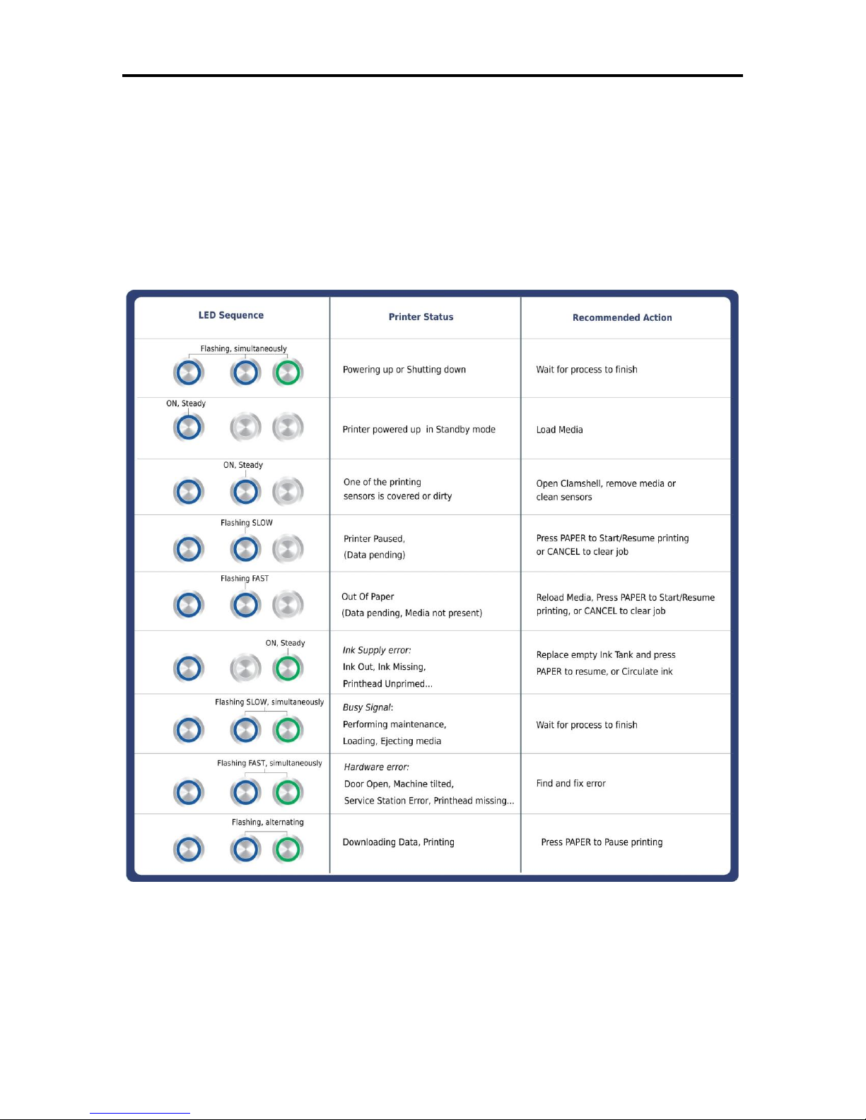
Control Panel LED Sequences
Print and cut out this chart to mount on the printer if desired. Suggested location: Top Cover.
Page 72

Page 73

Page 74

Copyright © 2014 ASTRO MACHINE CORP.
Elk Grove Village, IL 60007
12/02/2014
Part Number: 200-M1, Rev. T
 Loading...