

Page 1
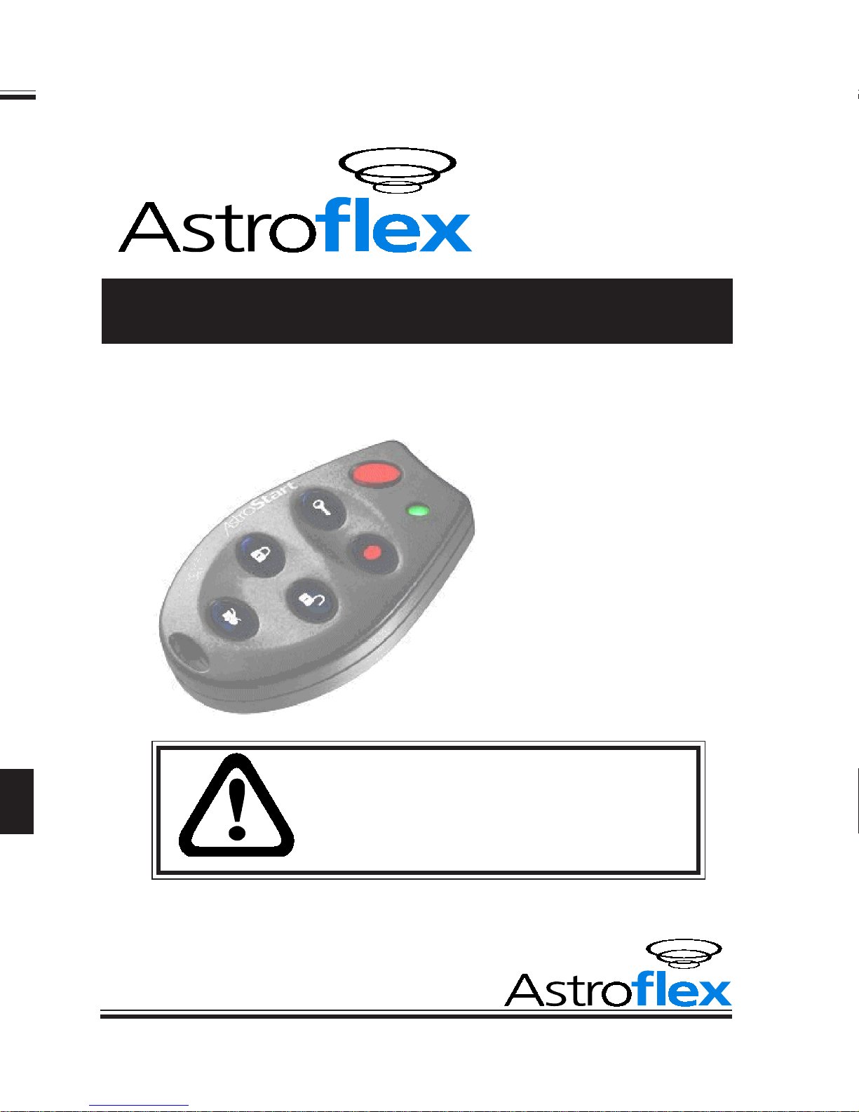
REMOTE
CONTROL
ENGINE
STARTER
Installation Manual
FOR
ALL AUTOMA TIC
TRANSMISSION GAS- AND
DIESEL POWERED VEHICLES.
SERIES
500, 1100,
2100, 4100
NOT FOR USE ON VEHICLES EQUIPPED
WITH MANUAL TRANSMISSION!
THIS PRODUCT MUST BE INST ALLED
BY
A QUALIFIED INSTALLER.
(Instructions en français au verso)
PA TENT NUMBERS
CAN 1.130.426
USA: 4.345.554 - 5.614.883
5.617.819 - 5.673.017
AND OTHER PATENTS PENDING
Litho’d in Canada
All rights reserved © Astroflex 2000
193-127-200-01
MANUFACTURED IN CANADA BY:
DÉMARREUR
DISTANCE
NOS. DE BREVETS
É.-U.: 4.345.554 - 5.614.883
5.617.819 - 5.673.017
ET AUTRES BREVETS EN INSTANCE
Lithographié au Canada
Tous droits réservées © Astroflex 2000
Page 2

T able of Contents
Quick Guide for Professionals 2
Quick Programming 6
Quick Programming Charts 7
(LEVEL 1 and 2)
Transmitter Coding 7
T achometer & Cylinder Settings 7
Detailed Programming 8
Programming Tables 9
(LEVEL 3 through 15)
Diagnostic Codes 1 2
Detailed Features 12
P2 : INPUT/OUTPUT 12
P2-1 &2 : Red 12
P2-3 : White/orange: P ARK / NEUTRAL INPUT 12
P2-4 : White/green: POSITIVE BRAKE SWITCH INPUT 13
P2-5 : Orange/white: WAIT TO ST ART (Glowplug) 13
P2-6 : Dark green: NEGA TIVE OUT WHEN RUNNING 13
P2-7 : Orange: ANTI THEFT OUTPUT 14
P2-8 : Light green: HORN OUTPUT 14
P2-9 : Red/white: +12V OUTPUT 15
P2-10 : Black/green: T ACHOMETER INPUT 15
P2-12 : Black/red: HOOD INPUT 16
P2-11 : Black: GROUND 16
P2-13 : Brown: PROGRAMMABLE OUTPUT #1 17
P2-14 : White/blue: PROGRAMMABLE OUTPUT #2 17
P2-15 : White: PROGRAMMABLE OUTPUT #3 17
P2-16 : Purple: PROGRAMMABLE OUTPUT #4 17
P3 : POWER DOOR LOCKS 17
P4 : MAIN POWER 18
P4-1 : Red: POWER INPUT 18
P4-2 : Y ellow: ACCESSORY OUTPUT 18
P4-3 : Green: P ARKING LIGHT OUTPUT 18
P4-4 : Orange: IGNITION OUTPUT 18
P4-5 : Dark blue: ST ARTER OUTPUT 18
P4-6 : Light blue: ST ARTER KILL INPUT 19
P4-7 : Red: POWER INPUT 19
P5 : ON-BOARD PROGRAMMABLE RELAY 19
P10 - P17 : CONNECTORS FOR PLUG-IN ACCESSORIES 19
P10 : TIMER CONTROL 19
P1 1 : VALET SWITCH 19
P13 : ON / OFF SWITCH 20
P14 : UNLOCK / LOCK CONNECTOR 20
P15 : ANTENNA CONNECTOR 20
P16 : ORIGINAL ALARM INTERF ACING CONNECTOR 20
P17 : P ARK T AB CONNECTOR 20
MAIN HARNESS TEST 21
POST-INST ALLA TION TESTS 22
ADDITIONAL TRANSMITTER CODING 2 2
Guide abrégé pour installateurs qualifiés 2
Programmation abrégée 6
Tableaux de programmation abrégée 7
(NIVEAUX 1 et 2)
Apprentissage des codes de télécommandes 7
Réglage du tachymètre et de la cylindrée 7
Programmation détaillée 8
Tableaux de programmation 9
(NIVEAUX 3 à 15)
Codes diagnostiques 1 2
Caractéristiques détaillées 1 2
P2 : ENTRÉE/SORTIE 12
P2-1 et 2 : RougeK12
P2-3 : Blanc/orange : ENTRÉE «P ARK» / NEUTRE 13
P2-4 : Blanc/vert : ENTRÉE INTERRUPTEUR DE FREIN 13
P2-5 : Orange/blanc : BOUGIES DE PRÉCHAUFFAGE 13
P2-6 : Vert foncé : SORTIE NÉGA TIVE LORSQU’EN MARCHE 13
P2-7 : Orange : SORTIE ANTIVOL 14
P2-8 : Vert pâle: SORTIE KLAXON 14
P2-9 : Rouge/blanc : SORTIE +12V 15
P2-10 : Noir/vert : ENTRÉE TACHYMÈTRE 15
P2-12 : Noir/rouge : ENTRÉE DU CAPOT 16
P2-11 : Noir : MASSE 16
P2-13 : Brun : SORTIE PROGRAMMABLE NO 1 17
P2-14 : Blanc/bleu : SORTIE PROGRAMMABLE NO 2 17
P2-15 : Blanc : SORTIE PROGRAMMABLE NO 3 17
P2-16 : Violet : SORTIE PROGRAMMABLE NO 4 17
P3 : VERROUILLAGE ÉLECTRIQUE DES PORTIÈRES 17
P4 : P
P4-1 : Rouge : ENTRÉE D'ALIMENT ATION 18
P4-2 : Jaune : SORTIE ACCESSOIRES 18
P4-3 : V ert : SORTIE FEUX DE POSITION 18
P4-4 : Orange : SORTIE D'ALLUMAGE 18
P4-5 : Bleu foncé : SORTIE DU DÉMARREUR 18
P4-6 : Bleu pâle : ENTRÉE DU COUPE-DÉMARREUR 19
P4-7 : Rouge : ENTRÉE D'ALIMENT ATION 19
P5 : RELAIS PROGRAMMABLE 19
P10 - P17 : PRISES DES ACCESSOIRES ENFICHABLES 19
P10 : MINUTERIE 19
P1 1 : COMMUTA TEUR «VALET» 19
P13 : INTERRUPTEUR ON/OFF 20
P14 : PRISE DÉ/VERROUILLAGE 20
P15 : PRISE D'ANTENNE 20
P16 : PRISE D’INTERFACAGE D'ALARME D'ORIGINE 20
P17 : PRISE «P ARK TAB» 20
VÉRIFICATION DU CÂBLE PRINCIPAL 21
VÉRIFICATIONS APRÈS INSTALLATION 22
PROGRAMMATION DE TÉLÉCOMMANDES ADDITIONNELLES 2 2
1
Page 3
Quick Guide for Professionals
This section of the installation manual is intended for experienced installers of
remote starter and mobile security products. Only the most frequently needed
information is included in the following few pages. It has been laid out to allow
you to quickly access connection and operational details to maximize your installation performance. Since most of the programming is set for popular defaults, you
will not need to make major , complex changes.
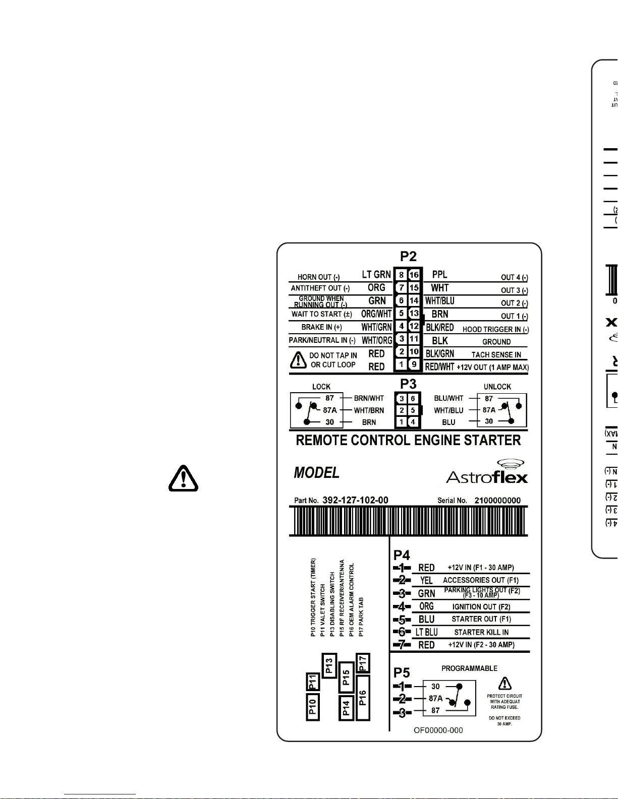
The following charts show the purpose of each wire on each connector and lists
the color code and pin position. Each of the first 5 charts are for a single connector . The last chart lists the connectors for the plug-in accessories.
Whenever you encounter a wire
that needs further explanation,
or need to access the virtually
unlimited programming flexibility of this Astrostart product, a
reference to the detailed installation instructions found later in
the manual will allow you to
understand all of the connection
and programming options
available. Additional information will be available on the
AstroChart CD ROM.
Each wire that provides a
(-) output can supply only
one single Bosch style
automotive relay.
2
Page 4

P2 CONNECTOR (models 500, 1100, 2100, 4100)
Note: Programmable outputs #1 & #2 (P2-13 & 14) also appear on the P16
connector. If you need programmable outputs while P16 is being used with
different settings, use programmable outputs #3 & #4 instead (P2-15 & 16).
3
CONNECTEUR P2 (modèles 500, 1100, 2100, 4100)
Remarque : Les sorties programmables 1 et 2 (P2-13 et 14) se retrouvent
également sur la prise P16. Si vous avez besoins de sorties programmable et
que la prise P16 est utilisée avec des réglages qui diffèrent des sorties
programmables 1 et 2, utilisez plutôt les sorties programmable 3 et 4 (P2-15
et 16).
NIPEMANROLOCESOPRUP
1- deR!tucronipaTtoNoD-A/N
2- deR!tucronipaTtoNoD-A/N
3
/kraP
lartueN
tupnihctiwS
/etihW
egnarO
ebtsumti;ecivedytirucesafotrapsitiucricsihT.rotceteDytefaSlartueN/kraP
.tinuniamnobaTkraP71Potdetcennoc
4
ekarB
)+(
/etihW
neerG
tupnI tratsetomerlecnactupniotelcihevehtfotiucricthgilekarbehtotdetcennoc
tsum-TIUCRICYTEFAS.hctiwslecnaclortnocesiurcotnitcennoctonoD.noitarepo
!detcennoceb
5
rogulPwolG
tratSdeyaleD
)±(
/egnarO
etihW
tupnI leseid(gulpwolGlitnuedomybdnatsniniamerottratsetomerswolla
).ces06otpu(.flestistaeherp)enigne .)+(sitluafeD enigneeht,detcennocnutfelfI
.)3LEVELees-.ces03rofelbammargorp(.ces06retfatratslliw
6
)-(tuptuO
gninnurnehw
neergkraD
tuptuO noitingiehterofebs1detavitcA.secivedtfehtitnaMEOhtiwecafretniotdesu
.ffotuhssinoitingiretfas1litnusniamerdna,tiucric
7)-(tfehtitnAegnarO
tuptuO DELrotiucrictfehtitnanalortnocotdesu
.)41egapno"TUPTUOTFEHTITNA"ees(
8)-(nroHneergthgiL
.)005tpecxE( tuptuO nA.tuptuolevelwolasisihT.nrohyrotcafehtetavitcaotdesu
selcihevniatrecnoderiuqerebyamyalerlanretxe
)sliatedlannoitiddarof41egapees(
9V21+etihW/deR
tuptuO naybdetcetorP.)slioc(syalerlanoitiddarofstloV21+desufedivorpotdesu
)snoitacilpparetratSdn2ronoitingIdn2roftoN:etoN(A1fo)CTP(esufteserotua
01tupnihcaT
/kcalB
neerG
)langishcat(langisdeslupasedivorptahtelcihevnitiucricotdetcennoC
.MPR008,lyc1:tluafeD .snoitpognimmargorprof51egaPeeS
11dnuorGkcalBottcennoC.dnuorGniaM lenapkciktfel ro llawerifylno .
21
nipdooH
.O.N)±(tupni
.C.Nro
deR/kcalB
ytiralopelbammargorP tupni .doohehtfogninepotcetedotdesu
.nepodoohnehwdesolcyllamroN:tluafeD
!detcennocebtsum-TIUCRICYTEFAS.snoitpognimmargorprof61egaPeeS
31
-margorP
)-(elbam
1#tuptuo
nworB
evitageN tuptuo .trahcsihtwolebetoneeS.yalerlortnocot1#
tratSerofeBesluP:tluafeD .
.snoitpognimmargorprof71egaPeeS
41
-margorP
)-(elbam
2#tuptuo
/etihW
eulB
evitageN tuptuo .trahcsihtwolebetoneeS.yalerlortnocot2#
.tratSretfAesluP:tluafeD
.snoitpognimmargorprof71egaPeeS
51
-margorP
)-(elbam
3#tuptuo
etihW
evitageN tuptuo .yalerlortnocot3#
.esaeleRknurT:tluafeD
.snoitpognimmargorprof71egaPeeS
61
-margorP
)-(elbam
4#tuptuo
elpruP
evitageN.)005tpecxE( tuptuo .yalerlortnocot4#
.thgiLemoD:tluafeD
.snoitpognimmargorprof71egaPeeS
1- eguoR!repuocsapentenoitavirédederiafysapeN-A/N
2- eguoR!repuocsapentenoitavirédederiafysapeN-A/N
3
4
5
6
7
8
9V21+
01
11essaMrioN
21
31
41
51
61
Page 5
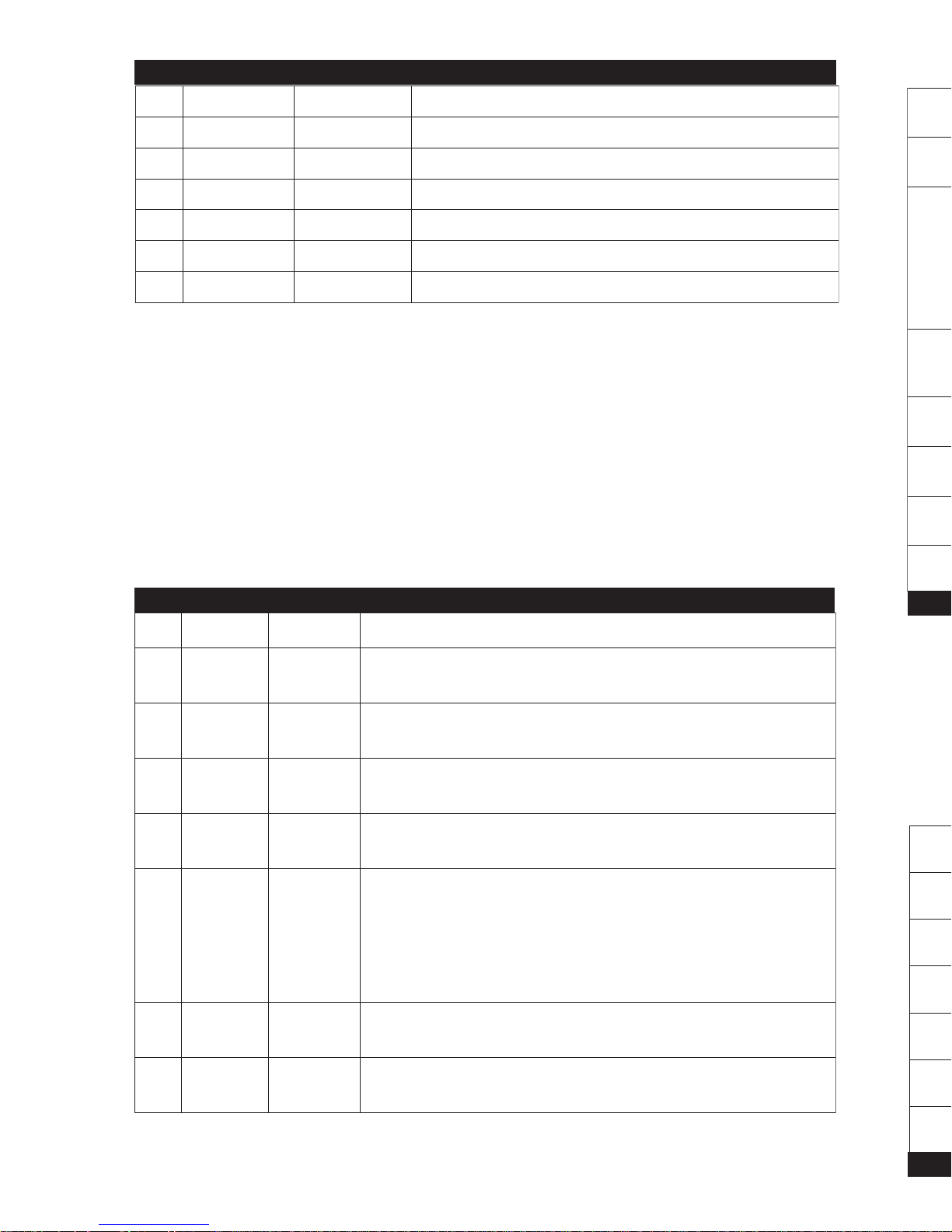
NOTE: FOR ALL ABOVE WIRES PLEASE SEE PAGE 17 FOR FURTHER DET AILS
Note: The P3 Connector accesses two fully programmable Bosch style relays
that are intended for power door lock interface.
4
P3 CONNECTOR (models 1 100, 2100, 4100)
P4 CONNECTOR (models 500, 1100, 2100, 4100)
NIPEMANROLOCESOPRUP
103-nommoCnworB.)KCOL(yalerepythcsoBevitomotuadradnatsfo03niP
2a78-CNnworB/etihW.)KCOL(yalerepythcsoBevitomotuadradnatsfoa78niP
378-ONetihW/nworB.)KCOL(yalerepythcsoBevitomotuadradnatsfo78niP
403-nommoCeulB.)KCOLNU(yalerepythcsoBevitomotuadradnatsfo03niP
5a78-CNeulB/etihW.)KCOLNU(yalerepythcsoBevitomotuadradnatsfoa78niP
678-ONetihW/eulB.)KCOLNU(yalerepythcsoBevitomotuadradnatsfo78niP
«etnemilA.)1F(pma03edelbisufnurapeégétorp,V21+eértnE
.»écnofuelblif-ruerraméD«te»enuajlif-seriosseccA
edxuefsedtiucriceletnemilA.)3F(A01edelbisufnurapégétorP
edfitisopsidnu'deitraptiafeitrosetteC.egamulla'dtiucriceletnemilA
.elucihévudegarramédedtiucricud»ruerraméd«étôcudehcnarbeS
resilartuenedtemreP.»egamulla«lifelrapeédnammoctseeitrosetteC
ecnatsidàegarramédudtnemomuaelucihévudegarramédedtiucricel
emmoctnemelagéeésilitU.esirpneertne'nruerramédeleuqretivéruop
elucihévudegarramédedtiucricud»tcatnocedélc«étôcudehcnarbeS
.lovitnafitisopsidemmoctnemelagéeésilitU.)tnemelues0014,0012(
noitisopedxueF«te»egnarolif-egamullA«etnemilaiuqV21+eértnE
NIPEMANROLOCESOPRUP
1tupnirewoPdeR
seilppus,)1F(esufA03aybdetcetorp,tupnirewopV21+
."eriWeulBkraD-retratS"ehtdna"eriWwolleY-yrosseccA"
2
yrosseccA
tuptuo
wolleY.)tiucricCA/retaeH(tiucricyrosseccaelcihevsdeeF
3
gnikraP
tuptuothgil
neerG.tiucricthgilgnikrapdeefotdesu,)3F(esufA01aybdetcetorP
4
noitingI
tuptuo
egnarO
ti;ecivedytirucesafotrapsitiucricsihT.tiucricnoitingisdeeF tsum eb
detcennoc yltcerid .tiucricnoitingis'elcihevot
5
retratS
tuptuo
eulBkraD
.tiucric"retratS"elcihevotstcennoC
.)ylno0014dna0012-noitpollikretratS(
ybdellortnocsituptuosihT.tiucricrotomretratsfoedisretratsotstcennoC
sielcihevnehwffotuhsebottiucricretratsswollA.eriw"noitingi"eht
sedivorposlA.rotomretratseht"gnidnirg"tneverpotdetratsetomer
.noitcnuftfehtitna
6
-retratS
tuptuolliK
eulBthgiL
desuoslA.)ylno0014,0012(.tiucricrotomretratsfoedisyekotstcennoC
.edomtfehtitnArof
7tupnirewoPdeR
neerG-sthgiLkraP"ehtdna"eriWegnarO-noitingI"sdeefhcihwtupniV21+
.)2F(esufpmA03aybdetcetorP."eriW
Page 6
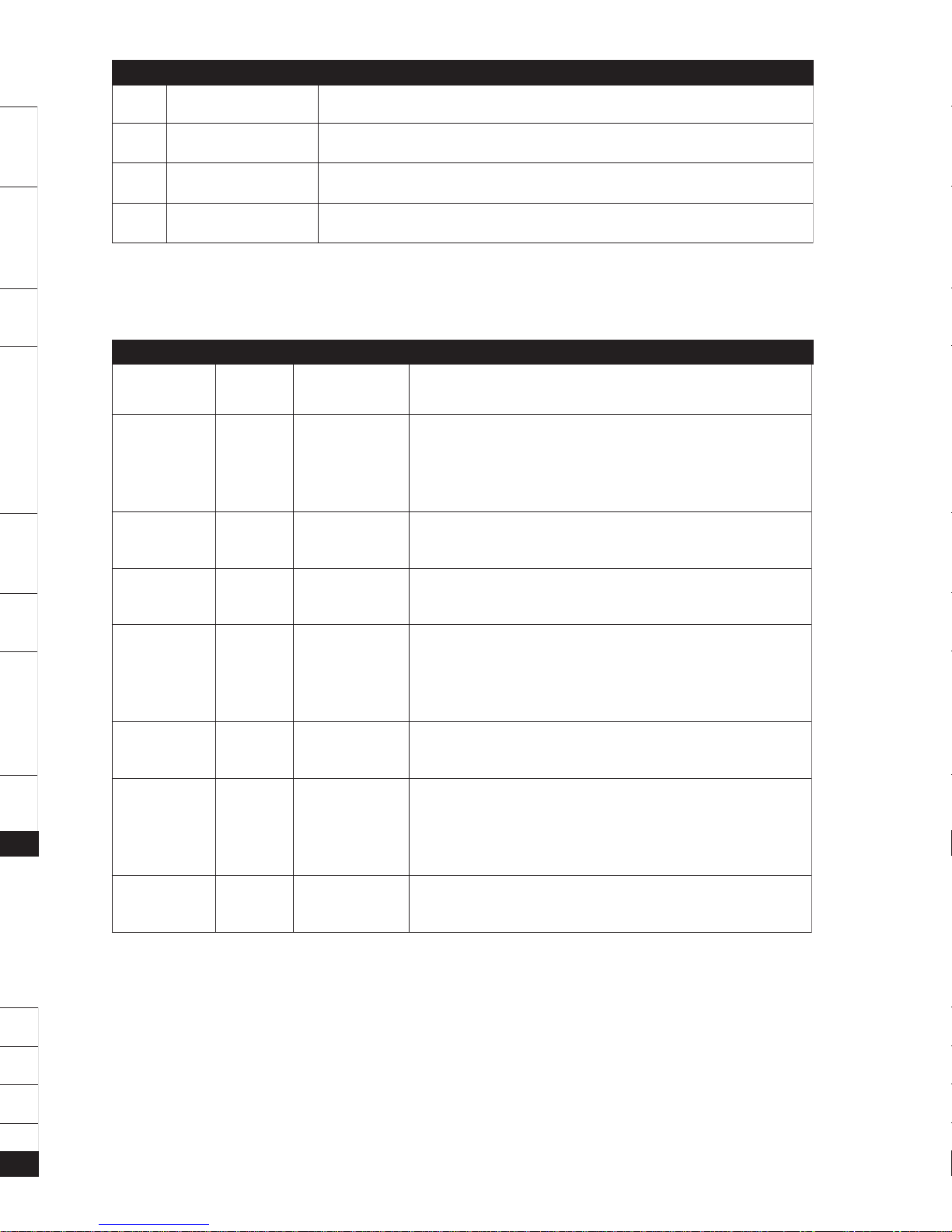
P5 CONNECTOR (models 1 100, 2100, 4100)
The default is set for Ignition. (Level 13) Power supply for this circuit must be
protected with an appropriate fuse.
PLUG-IN ACCESSORIES CONNECTOR LIST
5
CONNECTEUR P5 (modèles 1100, 2100, 4100)
La valeur par défaut est réglée pour Allumage (niveau 13). L’alimentation de ce
circuit doit être protégée par un fusible de calibre assortie.
LISTE DES CONNECTEURS POUR ACCESSOIRES ENFICHABLE
ROTCENNOC
ROF
LEDOM
EMANESOPRUP
01PLLA
DETACIDED
REMIT
LORTNOC
eboteludomremitlanoitponagniwollarotcennocnip-ruoF
.)XELFORTSAmorfelbaliava(tratsetomerehthtiwdecafretni
tratsetomerezilaitiniot).ces7.0(eslupevitagenaseriuqeR
.erudecorp
11P00140012HCTIWSTELAV
telavrofdellatsniebothctiwsagniwollarotcennocnip-eerhT
.snoitcnuf
31PLLA
FFO/NO
HCTIWS
.ffosnoitcnuftratsetomerehtnrutotelbaebotdesuhctiwS
.syaler"retratsdnaseirossecca,noitingi"slortnoC
41P005
/KCOL
KCOLNU
ecafretni1-ALDaotyltceridtcennocotrotcennocnip-eerhT
:tluafeD.syalerevirdotstuptuotnerrucwolevitagenro,eludom
eeS.noitamrifnoCon,kcolotuAoN,eslupdnoces7.0elgniS
.snoitpognimmargorprof11egaP
51PLLA
/ANNETNA
REVIECER
/annetnaFRehtotniyltceridsgulptahtrotcennocnip-ruoF
.eludomreviecer
61PLLA
/MRALA
REZILIBOMMI
GNICAFRETNI
ELUDOM
XELFORTSAnaotyltceridtcennocotrotcennocnip-thgiE
.eludomgnicafretnirezilibommi/mrala
.)eludomehthtiwdegakcapsliatedrehtrufeeS(
71PLLABATKRAP
othctiwsrotcelesraegfonoitcetedgniwollarotcennocnip-owT
.raegnitratst'nowelciheverusne
NIPEMANESOPRUP
103-NOMMOCyalerepythcsoBevitomotuadradnatsfo03niP
2a78-CNyalerepythcsoBevitomotuadradnatsfoa78niP
378-ONyalerepythcsoBevitomotuadradnatsfo78niP
Page 7
Quick Programming
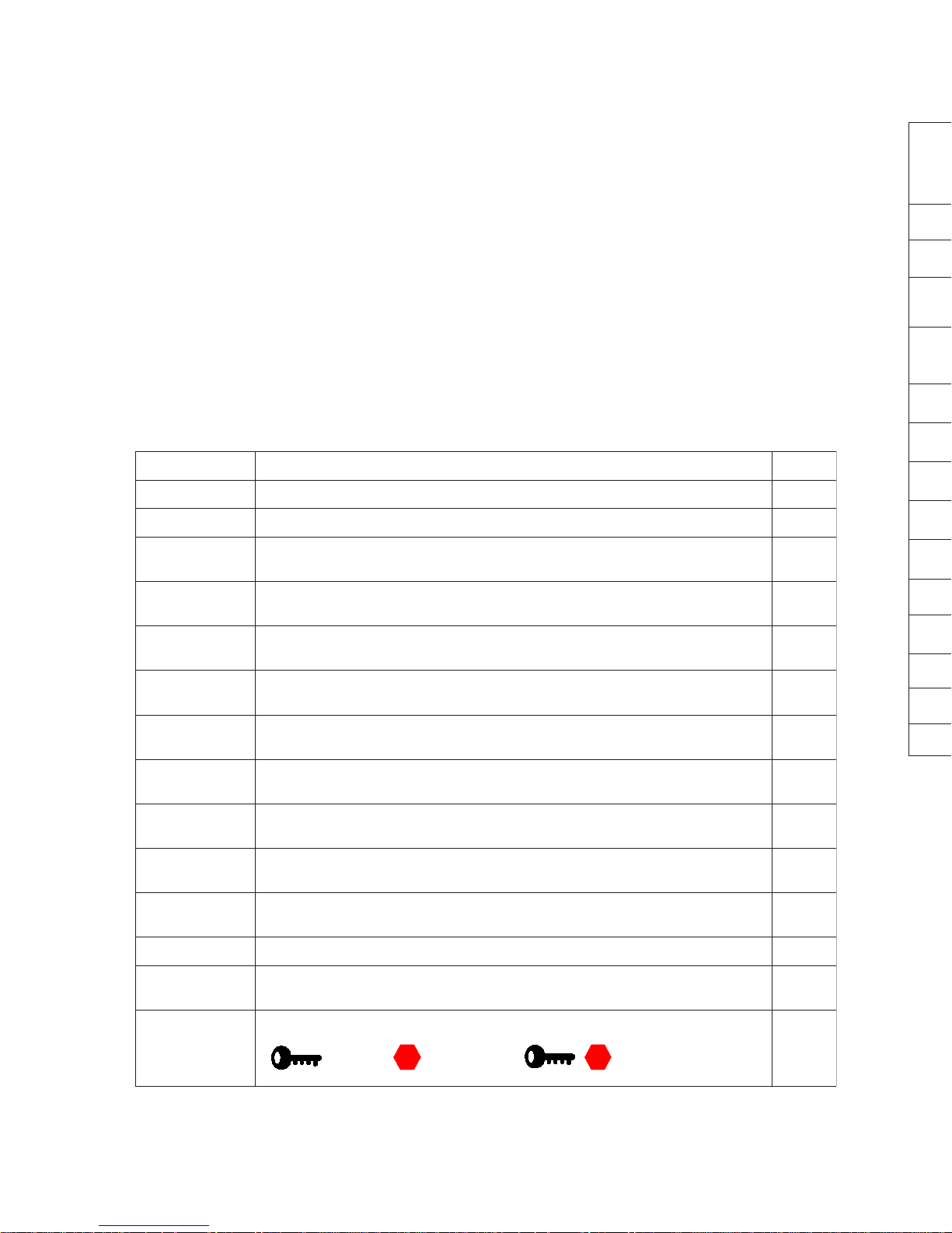
Y ou may believe that a product as versatile as the AstroStart would be a programming nightmare. In most cases, you will not need to change from the factory
default programming. In addition, Astrostart’s sophisticated processor allows
direct entry into a multitude of programming options with little effort.
All programming is performed through a 9 button DIP switch module. The
programming options for any feature are presented in the individual feature
explanation, which means there is no need to refer to a confusing but comprehensive master programming chart.
Will I Need To Reprogram a Feature?
Consult the following chart to determine if the defaults work for the installation. If
this chart reveals no required changes, move to the testing phase of the installation on page 21.
If changes to the default programming are required, please become familiar with
the following information in the programming charts.
6
1
udruetpurretni-egarramédedselcycselertneépuocegamulla-ecnesseàruetoM
3
lovitna-noitcnofsrohtnememraér-egarramédsèrpaseriossecca'dialédedsaP
4
-.ces7,0edegalliuorrev/édednoislupmI,.ces7,0edegamullAtnavAnoislupmI
ednoitamrifnoc-elpmis=egalliuorrevédednoislupmi-noitcnofsrohegalliuorrevotua
01
udeérud-.ces7,0ed2oneriatilitunoislupmi-.ces7,0ed1oneriatilitunoislupmI
.)tnemeluessnotuob6àednammocélét-noitcnofne(.ces03ed»euqinap«edom
11
8=ecnesse:ehcramedspmet-)F°5(C°51=ellenitnesedomuderutarépmeT
31
)FFO/NO(ELLENITNESTÊRRAEGARRAMÉD
51
CIPOTDELLORTNOCSERUTAEFTLUAFED LEVEL
srettimsnarT .denraelebtsumsetomerlanoitiddasselnuderetlaton-elbanEetomeR 1
enignE/hcaTdeepseldiMPR008,rednilyc1 2
enignE
noitarugifnoC
tcatnocdesolchctiwsdooH,selcycknarcneewtebffotucnoitingI,elcihevenilosaG
.neposidoohnehw
3
tfehtitnA
ytilibitapmoC
ffotfehtitnA,ffognimraeR,putratsretfayaledyrosseccaoN 4
elbammargorP
stuptuO
)1#tuptuoelbammargorp(erofebesluP 5
elbammargorP
stuptuO
)2#tuptuoelbammargorp(retfaesluP 6
elbammargorP
stuptuO
)3#tuptuoelbammargorp(knurT 7
elbammargorP
stuptuO
)4#tuptuoelbammargorp(thgilemoD 8
elbammargorP
yaleR
)yalerelbammargorp(noitingI 9
kcoLrooD
snoitpO
-eslupgnikcolnU,ffokcolotuA,eslupkcolnu/kcol.ces7.0,noitingIerofebeslup.ces7.0
ffonoitamrifnoceslupgnikcoLdn2,elgnis
01
stuptuOytilitU
noitarudcinaPdnoces03,2#eslupytilitudnoces7.0,1#eslupytilitudnoces7.0
)ylnosetomernottub6-nO(
11
emiTnuRenignEemitnur.nim61-leseiD,.nim8-enilosaG 21
pmeTlenitneS
emiTnuR&
leseidnim61-,sagnim8-lenitnesemitnuR,)Fº5(Cº51-erutarepmetedomlenitneS 31
setomeRnottuB-2
)ylno205ledom(gnidocedrettimsnartetomernottuB-2
)ffo/no(LENITNES=POTS=TRATS=
51
Page 8
Quick Programming Charts
(LEVEL 1 and 2)
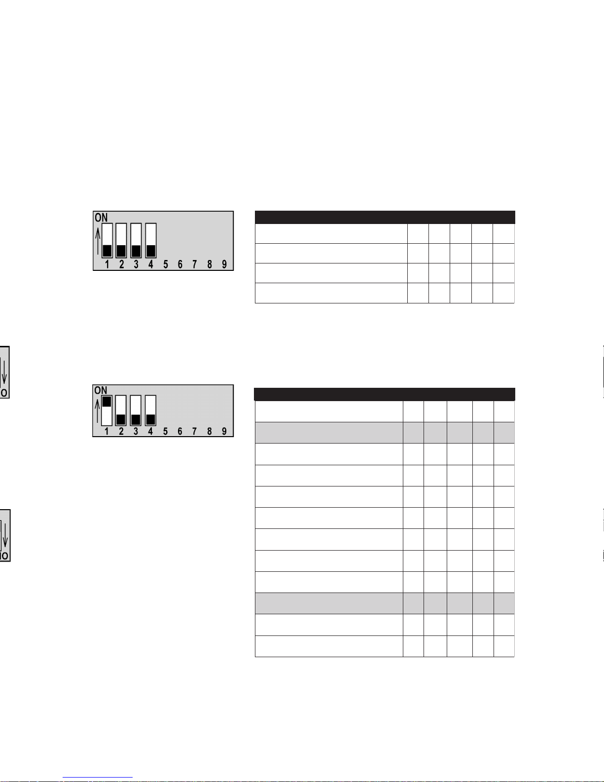
This information assumes that you understand how to program an Astrostart. If
not, refer to Detailed Programming.
In most cases you will need to program only the tachometer and cylinder setting,
and occasionally a remote transmitter.
Transmitter Coding
In the event that a transmitter needs to be re-coded, the following table outlines the
settings.
Tachometer & Cylinder Settings
Level 2 programming sets both IDLING SPEED and the vehicle’s number of cylinders (per tach signal).
In almost all cases, it is best to
start with the Auto Learn capability . See procedure on page 15.
TRANSMITTER CODING
7
hctiwSPID1LEVEL 56789
teseRgnimmargorPlaitinI
òò
PU
òò
gninraeLrettimsnarT
òòò
PU
ò
noitarepOlamroN
ттттт
LEVEL 1
LEVEL 2
ONCE DIP SWITCHES ARE SET , PRESS BRAKE PEDAL TO “LEARN” THE
FUNCTIONS.
Tableaux de programmation abrégée
(NIVEAUX 1 et 2)
Les renseignements qui suivent supposent que vous savez comment programmer un
démarreur AstroStart. Si tel n'est pas le cas, consultez la section relative à la programmation
détaillée.
En général, il suffira de programmer les réglages du tachymètre et du nombre de
cylindres, et parfois une télécommande.
Apprentissage des codes de télécommandes
Si une télécommande doit être reprogrammée, le tableau qui suit indique les réglages
qui sont requis.
Réglage du tachymètre et de la vitesse de ralenti
La programmation du niveau 2 permet de régler à la fois la vitesse de ralenti et le
nombre de cylindres (par circuit d’allumage).
En général, il est préférable de
procéder avec l'option
d'autoapprentissage d'abord.
UNE FOIS LE RÉGLAGE DES COMMUT A TEURS DIP EFFECTUÉ , APPUYEZ SUR LA
PÉDALE DE FREIN POUR QUE LA FONCTION SOIT MÉMORISÉE.
hctiwSPID2LEVEL56789
rednilyC1
ò ò ò
rednilyC2
PU
òò
rednilyC4-3
ò
PU
ò
rednilyC6-5
PUPU
ò
rednilyC8
òò
PU
rednilyC01
PU
ò
PU
rednilyC21
ò
PUPU
hcaTnraeLotuA
PUPUPU
MPR008
ò ò
MPR006
PU
ò
MPR005
ò
PU
T ACH & CYLINDERS
Page 9
Detailed Programming
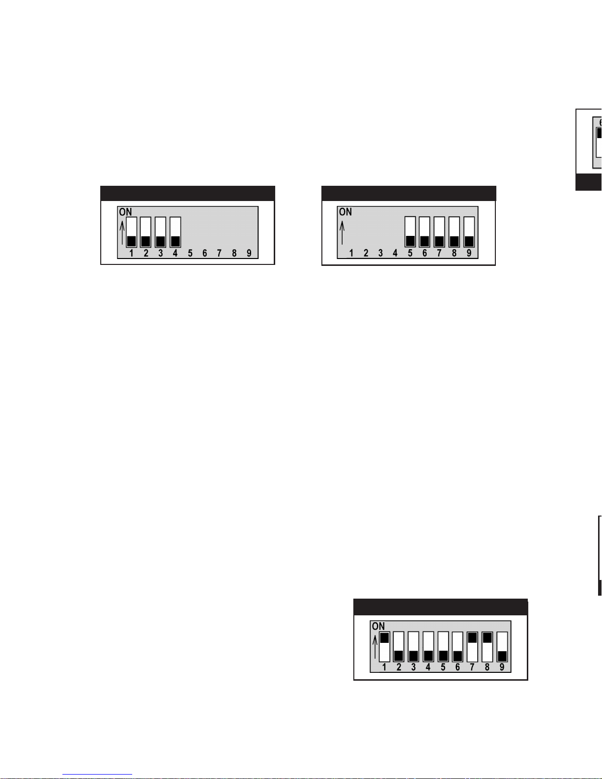
Programming is very simple once you have programmed your first Astrostart.
Programming parameters are divided into 15 groups called "levels" (see program-
ming tables, pages 9 to 12). These parameters are selected by setting a series of
9 DIP switches.
DIP switches 1, 2, 3 and 4 are used to
select programming levels.......
In each level, all parameters must be programmed in a single programming step.
Programming is accomplished as follows.
1) Set DIP switches 1, 2, 3 and 4 to select the feature’s LEVEL.
2) Set DIP switches 5 to 9 to combine options you wish to select.
3) Apply brakes to lock in the selected parameters in memory . LED flashes
same number of times as programming level selected, confirming that
parameters have been memorized in that LEVEL.
3a) Repeat steps 1 to 3 for each LEVEL that requires programming changes.
4) When programming is complete, put all DIP switches back to "OFF"
position, then apply brakes.
NOTE: IF YOU HA VE TO MAKE ANY PROGRAMMING CHANGES IN ONE
LEVEL, THE ENTIRE LEVEL MUST BE PROGRAMMED.
EXAMPLE
Imagine you have to program the Astrostart for an eight cylinder engine, with an
idle speed of 600 RPM.
1) Place DIP switches in following position:
a) DIP switches 1, 2, 3 and 4 for programming level 2.
b) DIP switches 5,6, & 7 determine number of cylinders.
c) DIP switch 8 & 9 determines idle speed.
2) Apply brakes, the LED flashes twice to
confirm level 2 settings have been
memorized.
3) When you have finished programming,
return all DIP switches to the OFF , then
apply brakes or select next level.
...while DIP switches 5 to 9 are
used to select options in each level.
8
t.
SETTING FEA TURES
SETTING PROGRAM LEVEL
SETTING EXAMPLE
Page 10
Programming Tables
(LEVEL 3 through 15)
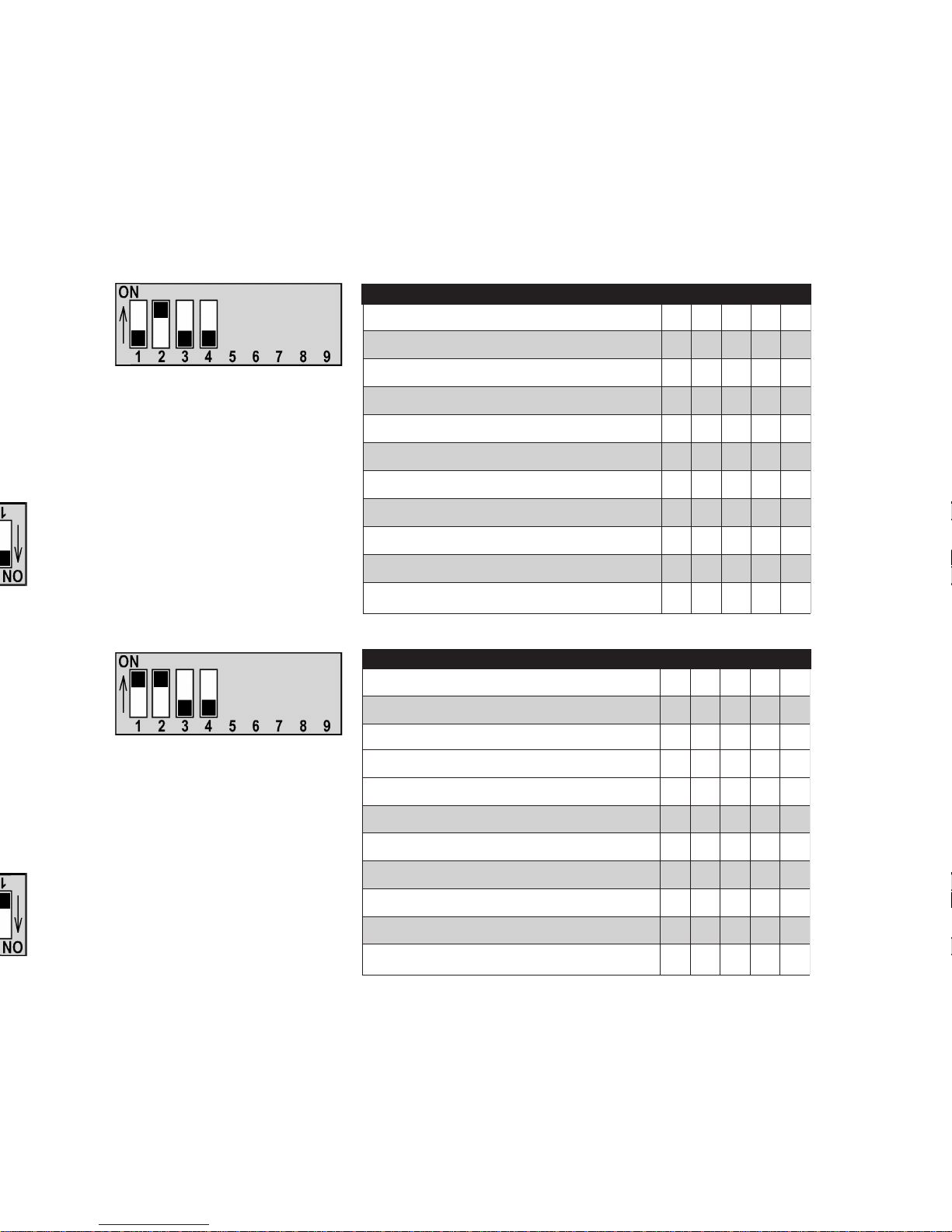
The following programming tables outline the settings for the remaining LEVELS.
Note that if you are changing one feature on a LEVEL, all of the other features on
that LEVEL need to be placed in the desired positions or they will be reset.
ENGINE CONFIGURA TION
Diesel: Positive & negative glow
plug settings are based on the glow
plug light being “ON”.
ANTITHEFT COMP ATIBILITY
Type 1 rearming is suited to North
American vehicles, while T ype 2 is
suited for Asian and European
vehicles.
9
Tableaux de programmation
(NIVEAUX 3 à 15)
Les tableaux de programmation qui suivent indiquent les réglages requis pour les
NIVEAUX qui restent. Remarque : même si un seul paramètre doit être réglé, le niveau
doit etre programmé en tenant compte de tous les paramètres qu’il comporte.
Diesel : les réglages positifs et
négatifs relatifs à la bougie de
préchauffage supposent que
son voyant est allumé.
Le réarmement de type 1
convient aux véhicules nord-
américains, tandis que le type 2
convient aux véhicules
asiatiques et européens.
hctiwSPID3LEVEL 56789
enignEenilosaG
ò
enignEleseiD
PU
)ylnoleseiD(etunim1sgulPwolG
ò
)ylnoleseiD(sdnoces03sgulPwolG
PU
tiucricsgulPwolGevitisoP
ò
tiucricsgulPwolGevitageN
PU
stpmettaknarcneewtebffOnruT:noitingI
ò
stpmettaknarcneewtebnOpeeK:noitingI
PU
hctiwsniPdooHdesolCyllamroN
ò
hctiwsniPdooHnepOyllamroN
PU
hctiwSPID4LEVEL 56789
ffO:ytiruceSyrotcaFgnimraeR
ò
nO:ytiruceSyrotcaFgnimraeR
PU
mraeR1epyT
ò
mraeR2epyT
PU
yaledoN-yaleDputratSyrosseccA
ò
yaleddnoces3-yaleDputratSyrosseccA
PU
oN:*metsyStfehtitnA
ò
seY:*metsyStfehtitnA
PU
*tfehtitnAepyTevissaP
ò
*tfehtitnAepyTevitcA
PU
LEVEL 4
LEVEL 3
* See P2-7 on page 14
Page 11
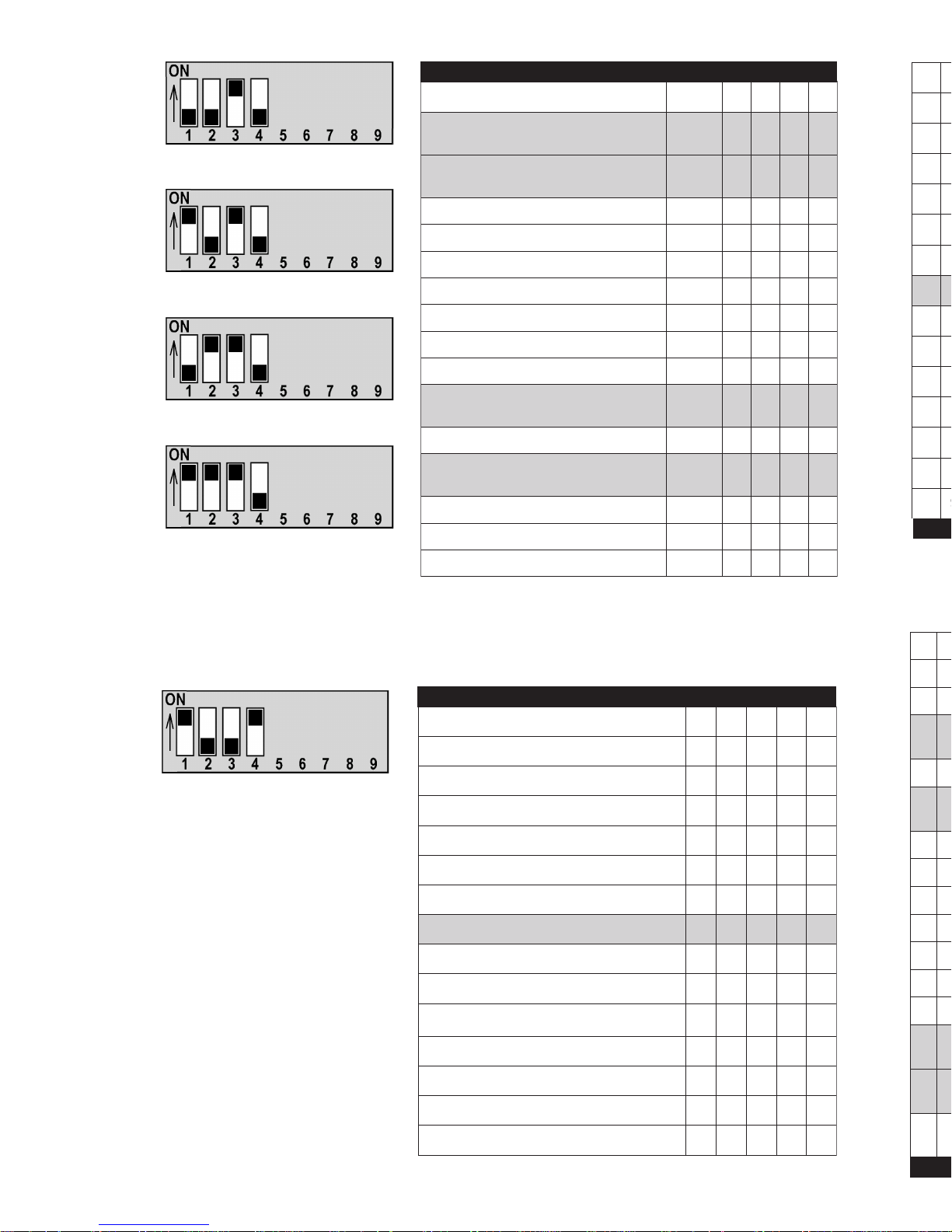
Defaults for Programmable Outputs:
Output #1= Pulse Before Start
Output #2 = Pulse After Shutdown
Output #3 = Trunk Release
Output #4 = Dome Light
PROGRAMMABLE RELAY
Default for Programmable Relay:
Ignition
LEVEL 5
LEVEL 6
LEVEL 7
LEVEL 8
hctiwSPID8&7,6,5LEVEL
tluafeD
LEVEL
6789
tratSerofeBesluP
)1#tuptuOtluafeD(
5
ò ò ò ò
nwodtuhSretfAesluP
)2#tuptuOtluafeD(
6
PU
ò ò ò
gninnuRelihWdnuorG
ò
PU
òò
sthgiLkraP
PUPU
òò
putratSretfAesluP
òòPUò
kcolnUdn2noesluP
PU
ò
PU
ò
noitingI
ò
PUPU
ò
yrosseccA
PUPUPU
ò
retratS
òòò
PU
esaeleRknurT
)3#tuptuOtluafeD(
7
PU
ò ò
PU
)noitarudetunim1(noitingIretfAnO
ò
PU
ò
PU
thgiLemoD
)4#tuptuOtluafeD(
8
PU PU
ò
PU
dekcoLelihWdnuorG
òò
PUPU
1ytilitU
PU
ò
PUPU
2ytilitU
ò
PUPUPU
PROGRAMMABLE OUTPUTS 1, 2, 3 & 4
hctiwSPID9LEVEL 56789
tratSerofeBesluP
òòòò
nwodtuhSretfAesluP
PU
òòò
gninnuRelihWdnuorG
ò
PU
òò
sthgiLkraP
PUPU
òò
putratSretfAesluP
òòPUò
kcolnUdn2noesluP
PU
ò
PU
ò
noitingI
ò
PU PU
ò
yrosseccA
PUPUPU
ò
retratS
òòò
PU
esaeleRknurT
PU
òò
PU
)noitarudetunim1(noitingIretfAnO
ò
PU
ò
PU
thgiLemoD
PUPU
ò
PU
1ytilitU
PU
ò
PUPU
2ytilitU
ò
PUPUPU
6789
ò ò ò ò
é ò ò ò
òéòò
ééòò
òòéò
éòéò
òééò
éééò
òòòé
é ò ò é
òéòé
é é ò é
òòéé
éòéé
òééé
òòòò
éòòò
òéòò
ééòò
òòéò
éòéò
ò é é ò
éééò
òòòé
éòòé
òéòé
ééòé
éòéé
òééé
LEVEL 9
10
Page 12
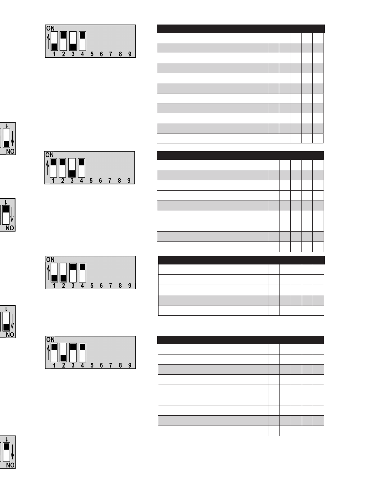
Diesel: Run times shown for Diesel
are based on LEVEL 3 being programmed to enable diesel options.
Default: -15° C (5° F), and 8 minutes
(gas)
Diesel: Run times shown for Diesel are
based on LEVEL 3 being programmed
to enable diesel options.
Default: 8 minutes (gas)
Default:
Utility 1 = 0.7 sec.
Utility 2 = 0.7 sec.
Alarm cycle = 30 sec.
Default:
Pulse before ignition = 0.7 sec.
Door Lock Pulse = 0.7 sec.
Autolock = OFF
Unlock Pulse = single
Second Unlock Confirmation = OFF
DURA TIONS: UTILITY 1 & 2 & PANIC
LOCK/UNLOCK OPTIONS
ENGINE RUN TIME
SENTINEL TEMPERATURE & RUN TIME
Réglages par défaut :
Imp. Avant Allumage = 0,7 sec.
Déverrouillage = 0,7 sec.
Autoverrouillage = OFF
Déverrouillage = simple
Confirmation = OFF
Réglages par défaut :
Utilitaire 1 = 0,7 sec.
Utilitaire 2 = 0,7 sec.
Cycle de l'alarme = 30 sec.
Réglage par défaut :
8 min. (essence); 16 min.
Diesel
Réglages par défaut :
Température = -15 °C (5° F)
Temps de marche = 8 min.
(essence), 16 min. Diesel
hctiwSPID01LEVEL 56789
.ces7.0=noitarudnoitingIerofebesluP
ò
.ces53.0=noitarudnoitingIerofebesluP
PU
sdnoces7.0=esluPkcoL/nUrooD
ò
sdnoces8.2=esluPkcoL/nUrooD
PU
ffOkcolotuA
ò
nOkcolotuA
PU
esluPkcolnUelgniS
ò
esluPkcolnUelbuoD
PU
FFOnoitamrifnoCkcoLdnoceS
ò
NOnoitamrifnoCkcoLdnoceS
PU
hctiwSPID11LEVEL 56789
sdnoces7.0=1ytilitU
ò ò
etunim1=1ytilitU
PU
ò
setunim8=1ytilitU
ò
PU
sdnoces7.0=2ytilitU
ò ò
etunim1=2ytilitU
PU
ò
setunim8=2ytilitU
ò
PU
sdnoces03=noitaruDcinaP/mralA
ò
sdnoces06=noitaruDcinaP/mralA
PU
hctiwSPID21LEVEL 56789
setunim4leseiD,setunim2saG
ò
PU
setunim8leseiD,setunim4saG
PUPU
setunim61leseiD,setunim8saG
ò ò
setunim63leseiD,setunim81saG
PU
ò
hctiwSPID31LEVEL 56789
pmeTnoitavitcAlenitneS)F°32(C°5-
PUPU
pmeTnoitavitcAlenitneS)F°5(C°51-
ò ò
pmeTnoitavitcAlenitneS)F°7-(C°02-
PU
ò
pmeTnoitavitcAlenitneS)F°22-(C°03-
ò
PU
emiTnuRlenitneS.nim4leseiD,.nim2saG
ò
PU
emiTnuRlenitneS.nim8leseiD,.nim4saG
PUPU
emiTnuRlenitneS.nim61leseiD,.nim8saG
ò ò
emiTnuRlenitneS.nim63leseiD,.nim81saG
PU
ò
LEVEL 10
LEVEL 11
LEVEL 12
LEVEL 13
11
Page 13
Detailed Features
P2 : INPUT/OUTPUT
P2-1&2 : Red
THESE PINS ARE NOT FOR INST ALLA TION USE. DO NOT CONNECT T O
ANYTHING!
12
Diagnostic Codes
When module is in operating mode (ready to start), the LED may display different
diagnostic codes for troubleshooting.
COMMAND RECEPTION
The LED flashes rapidly when command is sent to confirm that control module is
receiving remote control signals.
The LED flashes a certain number of times (see table) after an unsuccessful remote
start or run time interruption to indicate the reason for shutdown.
Code Reason for interruption
1 Stopped by remote control (trigger input - P10)
2 Stopped by applying brakes or (-) outputs are overloaded.
4 No tach reading (rpm)
5 Hood open
6 Transmission not in "P" or "N"
7 Ignition already in "ON" position
8 Main switch in "OFF" position or thermal protection (P2-9 and/or P10 to
P17 overloaded).
9 Run time expired
10 Start cycle expired
11 T ach signal already present
12 RPM above 3000
13 RPM below Idling
ò ò
éò
òé
51LEVEL56789
ò ò
PU
ò
ò
PU
- - Sentinel
- - Sentinel
- -
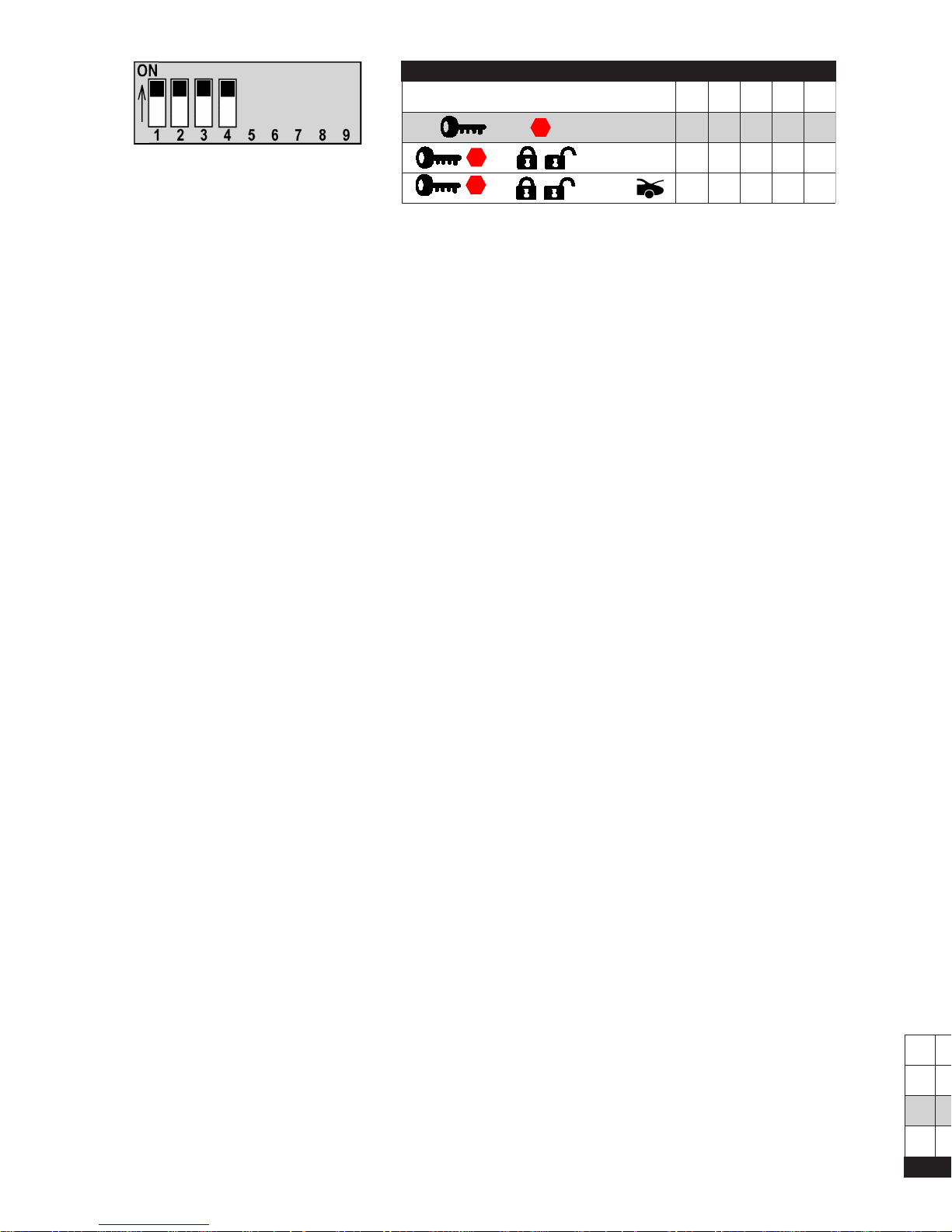
2-BUTTON REMOTE TRANSMITTER
Default :
Start - Stop -Sentinel
LEVEL 15
Page 14

P2-3 : White/orange: P ARK / NEUTRAL INPUT
Ground signal input which makes starting the vehicle possible when this wire
receives a signal from a park/neutral safety switch, or by connecting this wire to the
park tab wire (P-17). It is very important that the vehicle doesn’t remote start
when the gear selector lever is not in park or neutral.
This circuit is part of a safety device; it must be connected!
P2-4 : White/green: POSITIVE BRAKE SWITCH INPUT
This is a safety circuit that tells the control module to abort the starting cycle or to
disengage the module: it must be connected according to instructions below.
• Connect White/Green wire to brake lights circuit at brake pedal
switch (wire that provides +12 Vdc only when brakes are applied).
• Do not connect White/Green wire to cruise control cancelling
switch.
P2-5 : Orange/white: WAIT TO START (Glowplug)
This circuit is used to delay starting of the vehicle until the preheating of the diesel
engine has taken place. The cranking cycle is delayed until the glow plugs go out.
Find the glow plug light circuit in the dashboard and connect this wire to that
circuit.
Level 3 programming decides the polarity of the glow plug wire, and the glow plug
warm up time as well as the type of engine.
This connection is optional, but is highly recommended for optimal starting. If left
unconnected, the engine will start after 60 seconds regardless of when the engine
is ready . This feature can be programmed to 30 seconds in the LEVEL 3 programming.
The polarity of the glow plug circuit is determined by testing the circuit
with the glow plug light is illuminated.
Refer to Level 3 programming on page 9 for details.
P2-6 : Dark green: NEGATIVE OUT WHEN RUNNING
Negative output used to control original equipment anti theft devices. This output is
activated during the cranking cycle and is powered up 1 second before ignition
until 1 second after ignition. This could be used to disable a factory security system
or an anti theft device.
13
Blanc/orange : ENTRÉE « P ARK » / NEUTRE · P2-3
Entrée de signal de masse qui rend possible le démarrage lorsque ce fil reçoit un
signal de l'interrupteur de sécurité « Park» / Neutre, ou lorsque ce fil est branché à
« Park Tab » (P17). Il est essentiel que le véhicule ne puisse être démarré à
distance lorsque le levier de vitesses n'est pas en position « P » ou « N ».
Ce circuit fait partie d'un dispositif de sécurité. Il doit être branché!
P2-4 : Blanc/vert : ENTRÉE POSITIVE INTERRUPTEUR DE FREIN
Il s'agit d'un circuit de sécurité qui sert à neutraliser le cycle de démarrage, il doit
être branché selon les consignes qui apparaissent ci-dessous.
Sur les véhicules diesel, ce circuit permet de retarder le démarrage jusqu'au
moment où le préchauffage est complété. Le cycle de démarrage est retardé
jusqu'à ce que les bougies s'éteignent.
Localiser le circuit du voyant de la bougie de préchauffage au tableau de bord et y
brancher le fil.
Le niveau de programmation 3 décide du type de moteur , de la polarité du circuit de
la bougie de préchauffage, ainsi que de sa durée.
Ce branchement est facultatif, mais on le recommande fortement pour faciliter le
démarrage. Si le branchement n'est pas fait, le moteur va démarrer après 60
secondes qu'il soit réchauffé ou non. Cette option est programmable à 30
secondes au NIVEAU 3.
La polarité du circuit de la bougie de préchauffage est déterminée en
testant le circuit alors que le voyant de la bougie de préchauffage est
allumé.
Se référer à la section de programmation à la page 9 pour plus de détails.
P2-6 : Vert foncé : SORTIE NÉGATIVE LORSQU’EN MARCHE
Sortie négative utilisée pour commander les dispositifs antivol d'origine. Cette
sortie est activée 1 seconde avant le démarrage, elle demeure maintenue pendant
le temps de marche puis, est coupé 1 seconde après la fin du temps de marche.
Elle peut servir à mettre hors circuit un système de sécurité installé en usine ou un
système antivol.
Page 15
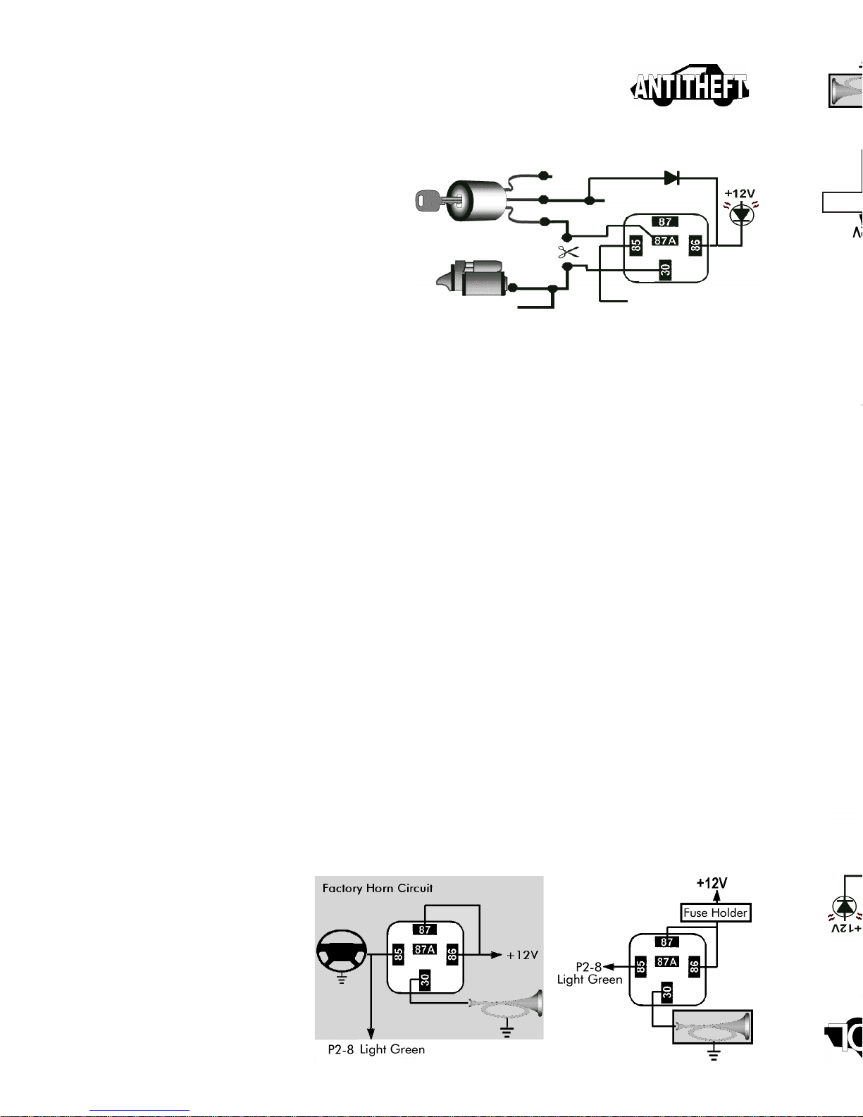
Anti theft Output
P2-7 : Orange: ANTI THEFT OUTPUT
Note: On Model 500 do not use if module is not configured to accept
<<UNLOCK>> function.
Negative output used to control a relay
that neutralizes a vehicle circuit to
prevent starting, or an LED to indicate
antitheft status.
Following example illustrates how to
connect a start-disable circuit.
Active Anti theft Mode
When this output is programmed in “ACTIVE” mode, it will become activated when the
locking function is received and deactivated when the unlocking function is received.
Passive Anti theft Mode
When the anti theft output is programmed in “PASSIVE” mode the circuit is deactivated
in the same manner as the active mode, and it is activated 60 seconds after the ignition
switch is turned off. During this delay, if the ignition switch is turned back on, this mode
is then cancelled and the anti theft will wait for another transition from “on” to “off”. Once
the anti theft is activated, turning the ignition back on will not affect the anti theft feature.
In addition, this output is deactivated for 60 seconds if an “UNLOCKING” function is
received. During this delay if the ignition has not been switched from “OFF” to “ON” the
anti theft will remain activated
Anti theft “Valet” Mode
(Models 2100 and 4100 only).
Mode selectable on LEVEL 4, Default OFF. The “Valet” input serves to permanently
control the anti theft output up to 10 cycles of the ignition switch being turned on then off.
The anti theft valet mode will be deactivated by pressing the push button for 3 seconds
while ignition is ON. See P-11 for switch connection.
(Other models)
For other models, it is possible to add a toggle switch in series with the anti theft output
(P2-7) to cancel anti theft function.
P2-8 : Light green: HORN OUTPUT
(Except Model 500)
Negative output used to
activate the factory horn
circuit (low current) or an
external relay. Could be
hooked to the vehicles
factory horn to give an
added audible verification.
14
Porte-fusible
IGNITION
ANTI THEFT
OUTPUT
P2-7
ST ARTER
OUTPUT
P4-5
P2-7
Page 16
P2-9 : Red/white: +12V OUTPUT
Output used to feed external accessories relays. These outputs are protected by an
auto reset fuse (PTC) of 1A.
P2-10 : Black/green: TACHOMETER INPUT
Input used to detect engine is running.
GAS-POWERED VEHICLES :
Connect Black/Green wire to negative terminal of ignition coil or
to signal input on ignition module.
Note: For additional protection, it is recommended that a 0.5
amp fuse is added at the junction to ignition coil.
Astroflex has regrouped useful information related to vehicle
circuitry (wire colors) on CD ROM available under P/N 193-901-204.
DIESEL-POWERED VEHICLES :
Y ou have to add a (DTS-2) module which converts electromagnetic fields generated by alternator into a tach signal.
Wiring instructions are supplied with kit (310-066-502).
AUTOMA TIC TACH LEARNING
Place DIP switches as illustrated, start vehicle using key then apply
brakes.
The tach-learning section takes a little
over 4 seconds to detect the number of
cylinders. After this delay , the unit will
come out of tach learn mode.
When tach signal is detected, LED will flash same
number of time as number of cylinder selected.
If tach learn mode fails, the remote start programs
actual settings for DIP switch 8 & 9 (idling speed)
and the cylinder setting will remain the same as it
was before programming started (see LEVEL 2
programming on page 7).
An installer can therefore change the parameters of DIP 8 & 9 without worrying
about the number of cylinders previously programmed.
The technician would simply have to put DIP switches 5, 6, & 7 to automatic tach
learn mode, but do not start the car; thus tach learn mode will fail maintaining
the original cylinder setting but allowing you to program the new idle speed.
CANNOT BE PROGRAMMED UNTIL INST ALLATION IS COMPLETE
15
P2-9 : Rouge/blanc : SORTIE +12V
Sortie d'alimentation pour relais d'accessoires externes. Ces sorties sont protégées par
un fusible à réenclenchement automatique (PTC) de 1A.
P2-10 : Noir/vert : ENTRÉE TACHYMÈTRE
Entrée de détection de l’état de marche du moteur .
VÉHICULES À ESSENCE :
VÉHICULES DIESELS :
L'ajout d'un module DTS-2 est nécessaire. Ce module convertit le champ
électromagnétique produit par l'alternateur en un signal de tachymètre.
Des consignes d'installation accompagnent l'ensemble (310-066-502).
AUTOAPPRENTISSAGE DU T ACHYMÈTRE
Réglez les commutateurs DIP tel qu’illustré ci-contre. Faite démarrer le véhicule à l’aide
Lorsque le signal de tachymètre est détecté, la DEL
clignote un nombre de coups égale au nombre de
cylindres programmés.
Si l'apprentissage échoue, la commande de démarrage
accepte le réglage actuel des commutateurs DIP 8 et 9
(vitesse de ralenti), tandis que le nombre de cylindres demeure ce qu’il était auparavent
(voir la programmation du NIVEAU 2 en page 7).
Il est possible de modifier les paramètres des commutateurs DIP 8 et 9 sans pour
autant effacer le nombre de cylindres programmé. Il suffit de placer les commutateurs
DIP 5, 6 et 7 en mode d'apprentissage automatique du tachymètre sans faire démarrer
le véhicule.
Ainsi, l'apprentissage va échouer , ce qui va maintenir le réglage du nombre de
cylindres, tout en permettant de programmer la nouvelle vitesse de ralenti.
PROGRAMMATION POSSIBLE SEULEMENT UNE FOIS L'INSTALLA TION TERMINÉE
Page 17
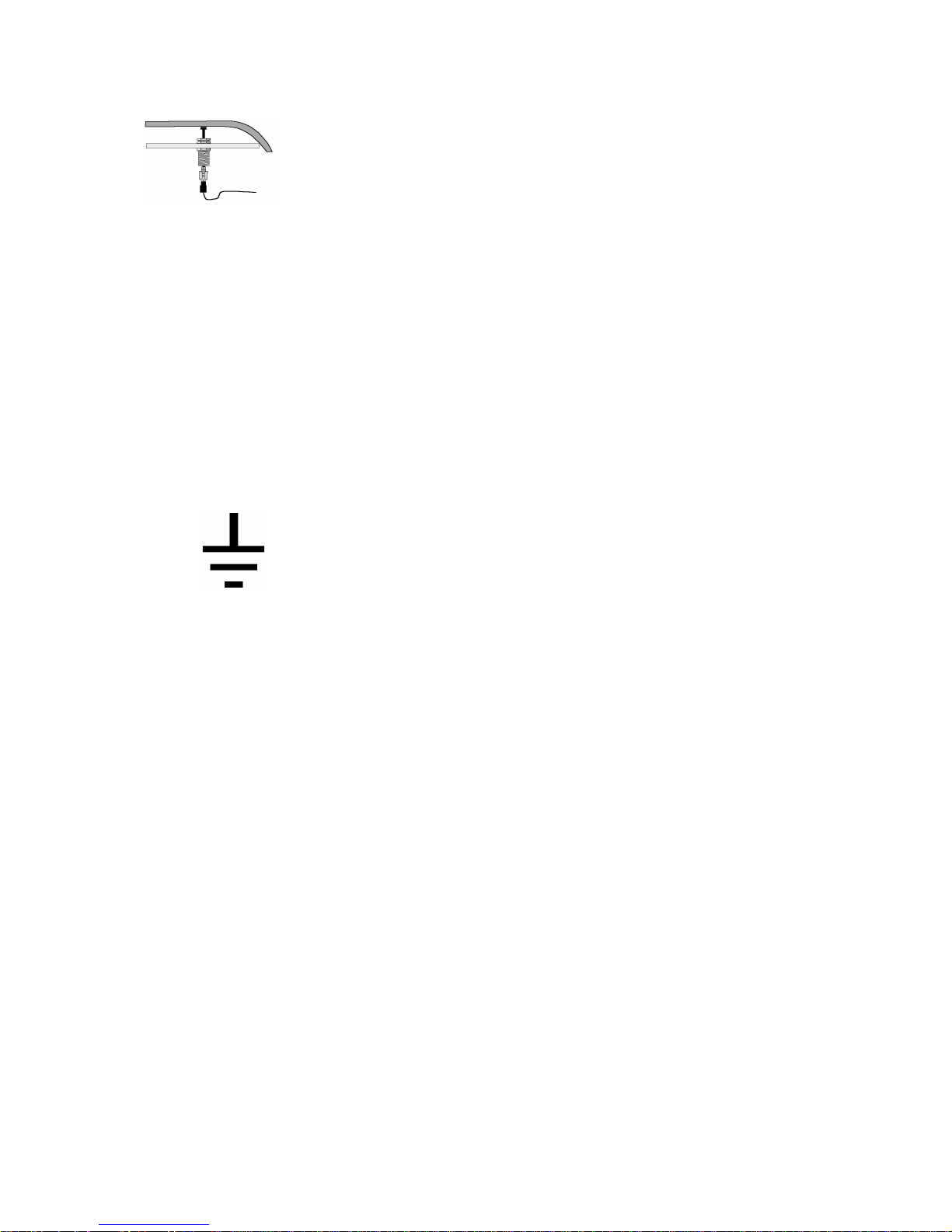
P2-12 : Black/red: HOOD INPUT
Programmable polarity input allowing the module to detect the
hood being opened.
This circuit is a safety feature that must be hooked up.
• Run Black/red wire into engine compartment through a
rubber grommet. Cover wire with plastic loom and secure with plastic ties, away
from any heat source or sharp metal parts.
• Install switch at the front of the engine compartment to ensure it activates the
shut down feature when hood is lifted up about 2 cm (1/2 in.)
• Always make sure that the correct polarity is selected for the type of pin switch
being used.
Hood PIN switch polarity is programmed in LEVEL 3.
P2-11 : Black: GROUND
Input that provides a reference ground for the module.
AL W AYS ENSURE BLACK WIRE IS CONNECTED
TO THE LEFT KICK PANEL OR THE FIREWALL.
16
Page 18
P2-13 : Brown: PROGRAMMABLE OUTPUT #1
Negative output where the function can be determined during LEVEL 5 programming. In this instance the factory programmed setting is PULSE BEFORE.
P2-14 : White/blue: PROGRAMMABLE OUTPUT #2
Negative output where the function can be determined during LEVEL 6 programming. In this instance the factory programmed setting is PULSE AFTER.
P2-15 : White: PROGRAMMABLE OUTPUT #3
Negative output where the function can be determined during LEVEL 7 programming. In this instance the factory programmed setting is TRUNK RELEASE.
P2-16 : Purple: PROGRAMMABLE OUTPUT #4
(Except Model 500)
Negative output where the function can be determined during LEVEL 8 program-
ming. In this instance the factory programmed setting is DOME LIGHT.
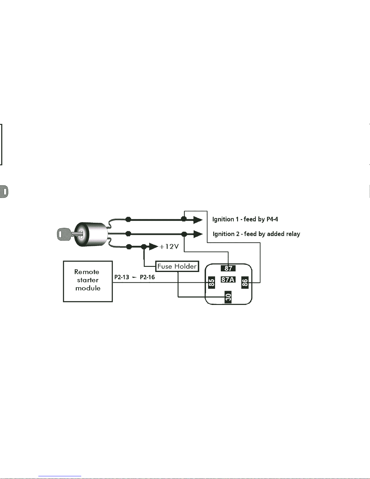
Wiring example for applications using programmable (-) outputs.
P3 : POWER DOOR LOCKS
(Model 1100, 2100 and 4100)
This harness provides on board relays for power door lock interfaces. Please refer
to the AstroChart CD for descriptions of door lock hookups.
Programming for options related to this connector is obtained in LEVEL 10.
17
Programmable (-)
output 1 - 4 set in
‘Ignition’ mode
P2-13 : Brun : SORTIE PROGRAMMABLE NO 1
Sortie négative dont la fonction peut être déterminée lors de la programmation du
NIVEAU 5.
Dans ce cas-ci, le réglage par défaut est IMPULSION A V ANT .
P2-14 : Blanc/bleu : SORTIE PROGRAMMABLE NO 2
Sortie négative dont la fonction peut être déterminée lors de la programmation du
NIVEAU 6.
Dans ce cas-ci, le réglage par défaut est IMPULSION APRÈS.
P2-15 : Blanc : SORTIE PROGRAMMABLE NO 3
Sortie négative dont la fonction peut être déterminée lors de la programmation du
NIVEAU 7.
Dans ce cas-ci, le réglage par défaut est OUVERTURE DU COFFRE.
P2-16 : Violet : SORTIE PROGRAMMABLE NO 4
(sauf modèle 500)
Sortie négative dont la fonction peut être établie lors de la programmation du
NIVEAU 8.
Dans ce cas-ci, le réglage par défaut est PLAFONNIER.
EXEMPLE de raccordement qui peut etre réalisé sur les sorties (-) programmables.
P3 : VERROUILLAGE ÉLECTRIQUE DES PORTIÈRES
(modèles 1 100, 2100 et 4100)
Cette prise est reliée à des relais incorporés pour les interfaces de verrouillage
électrique des portières. Se reporter au cédérom AstroChart pour une description
des branchements appropriés.
La programmation des options relatives à cette prise s’effectue au NIVEAU 10.
Page 19
P4 : MAIN POWER
P4-1 : Red: POWER INPUT
30 Amp input that provides power to the yellow accessory wire and the blue start wire.
This wire should be hooked to a circuit in the main ignition switch harness that is
capable of providing 30 amps of current. When there is more than one feed
circuit, use circuit that supplies most power or has largest gauge wire.
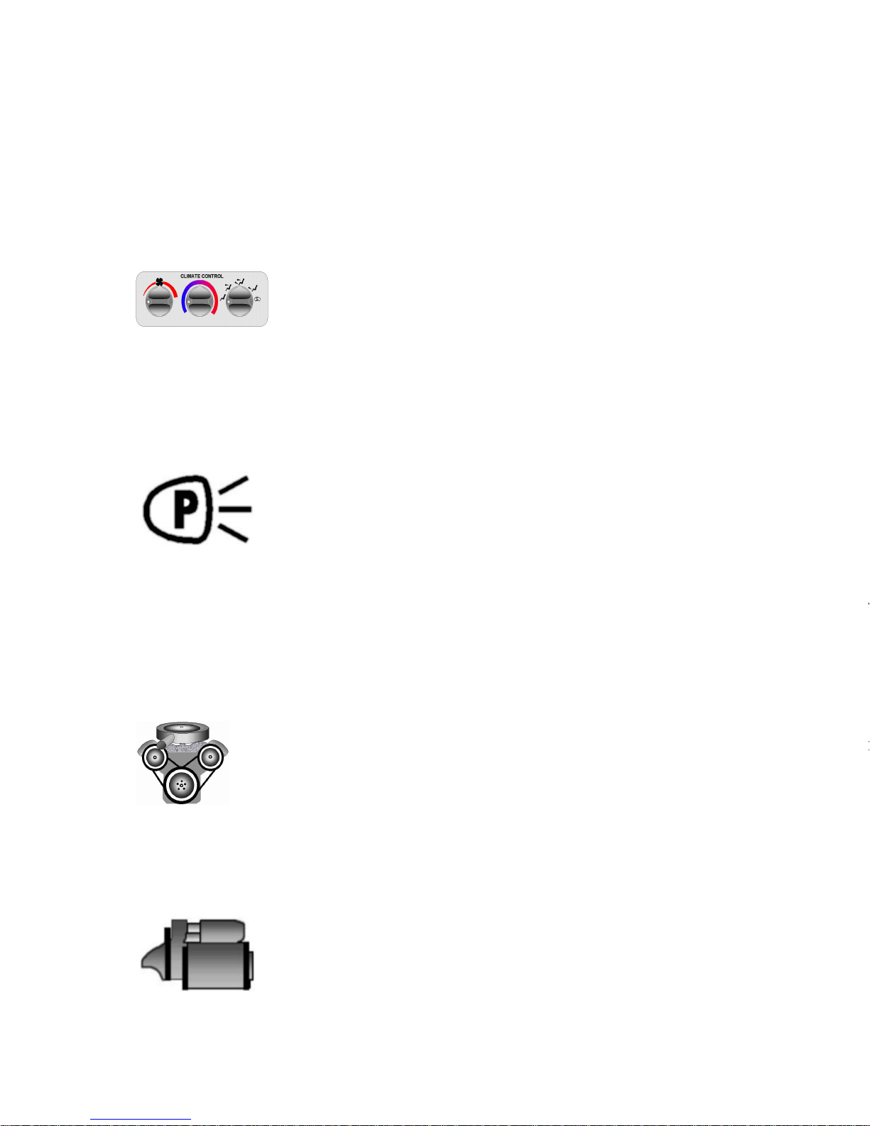
P4-2 : Yellow: ACCESSORY OUTPUT
Provides power to energize the vehicles climate control circuit.
Climate control circuit will sometimes have 2 or more wires
needing power in order to turn on the air conditioning compressor and heater fan motor. If more than one circuit is required additional relays
must be added to ensure vehicle’s circuits maintain their isolation.
(See Programmable outputs P2-13 to P2-16.)
P4-3 : Green: PARKING LIGHT OUTPUT
This wire provides an output to trigger the vehicles parking light
circuit to add a visual verification of the modules functions.
Locate the parking light circuit, making sure this circuit is a park
light circuit and not a dash light circuit, as a dash light circuit
will have a voltage that varies depending on the position of the
dash dimmer control. USE A DMM (Digital MultiMeter)
INSTEAD OF A TEST LIGHT TO TEST THIS CIRCUIT!
Parking lights give a visual confirmation when commands are received and starter
is in operation.
P4-4 : Orange: IGNITION OUTPUT
Provides power to the vehicles ignition circuit. This is a circuit that is
required to make the car run and keep running. This circuit is part
of a security device; it must be connected directly to the vehicle’s
main ignition circuit. Newer vehicles can have multiple ignition
wires in the main ignition switch harness and additional relays are
required to maintain circuit isolation and provide enough outputs
for all these circuits. (See Programmable outputs P2-13 to P2-16.)
P4-5 : Dark blue: STARTER OUTPUT
+12V output used to supply power to the starter motor in the
vehicle. This is another circuit that could have multiple wires, so
the need for additional relays is essential to maintain isolation
in the vehicle. This wire must go to the starter motor side of the
start wire if using the starter cut relay option.
(See Programmable outputs P2-13 to P2-16.)
18
Page 20

P4-6 : Light blue: STARTER KILL INPUT
(Model 2100 & 4100 only)
Input wired to the normally opened contact of a relay (contact 87A) which allows
the module to cut off the starter circuit when the vehicle is remotely running or
when the anti theft mode is actif and the ignition is turned on. This relay is controlled by the “ignition” output, while the common contact is connected to the starter
output. This wire can be programmed for use in antitheft applications as outlined
in LEVEL 4 programming.
P4-7 : Red: POWER INPUT
Power input wire that is protected by a 30A in-line fuse which provides power for
the “Ignition-Orange wire” and the “Park Lights-Green wire” outputs.
P5 : ON-BOARD PROGRAMMABLE RELAY
(Except Model 500)
This is a three-pin connector connected to an internal standard automotive style
relay, ie. COMMON-30, NO (normally open)-87 and NC (normally closed)-87A.
Please refer to page 10 for explanation of selectable features for this LEVEL 9
programmable output.
NOTE: Use adequate fuse rating for all 12 volt supply wiring.
P10 - P17 : CONNECTORS FOR PLUG-IN ACCESSORIES
P10 : TIMER CONTROL
This is a four-pin connector which permits an ASTROFLEX timer (or similar Negative pulse device) to trigger the start up procedure of the remote start.
P11 : VALET SWITCH
(2100 and 4100 only)
Three-pin connector allowing a push button switch to be plugged into the module
to control the “Valet” mode functions.
This switch should be mounted in a location accessible to the operator , yet hidden
from plain view.
19
P4-6 : Bleu pâle : ENTRÉE DU COUPE-DÉMARREUR
(modèles 2100 et 4100 seulement)
Entrée reliée au contact normalement ouvert d’un relais (contact 87A) permettant au
module de couper le circuit de démarrage lorsque le module est en fonction ou lorsque le
mode Antivol est actif et que la clé de contact est en position « ON ». Ce relais est
commandés par la sortie « allumage », tandis que le contact commun est branché à la
sortie démarrage. Ce circuit peut etre programmé en mode « Antivol » au niveau 4 de la
programmation.
P4-7 : Rouge : ENTRÉE D'ALIMENTATION
Fil d'alimentation, protégé par un fusible de 30 ampères, qui fournit du courant aux sorties
des fils « Allumage-Orange » et « Feux de position-V ert ».
P5 : RELAIS PROGRAMMABLE
(sauf modèle 500)
Il s'agit d'une prise à trois broches branchée à un relais interne standard pour automobile,
c'est-à-dire COMMUN-30, N.O. (normalement ouvert)-87 et N.F. (normalement fermé)-
87A.
Se reporter à la page 10 pour plus de détails sur les options possibles de cette sortie
programmable du NIVEAU 9.
REMARQUE : Utiliser un fusible de calibre approprié pour tous les fils d'alimentation de
12V .
P10 - P17 : PRISES DES ACCESSOIRES ENFICHABLES
P10 : MINUTERIE
Il s'agit d'une prise à quatre broches qui permet à une minuterie ASTROFLEX (ou à un autre
dispositif à impulsion négative) de déclencher le processus du démarrage à distance.
P11 : COMMUTATEUR « VALET »
2100 et 4100 seulement)
Prise à trois broches qui permet de brancher un commutateur à bouton poussoire au
module afin de commander les fonctions du mode « valet ».
Ce commutateur devrait être installé à un endroit facilement accessible par l'utilisateur mais
à l'abri des regards.
Page 21

P13 : ON/OFF SWITCH
Three-pin connector designed for a plug in on/off switch. This switch overrides the
remote start functions, yet maintaining all other functions.
Switch should be mounted in a location easily accessed by the operator such as
under dashboard where driver can reach it.
P14 : UNLOCK/LOCK CONNECTOR
(Model 500 only)
This three-pin connector is a negative trigger low current output designed to drive
DLA-1 interface or Bosch style relays.
P15 : ANTENNA CONNECTOR
A four-pin connector for direct connection to the supplied antenna. The antenna
should be mounted usually on the front windshield.
•Mount antenna below the tint strip on the windshield, or if no tint strip is on the
windshield, install the antenna about 10 cm (3-1/2 in.) from the roof line.
•Next, mount receiver on antenna ensuring that contacts are aligned and that
connector faces up.
•Press on receiver module from left to right to compress V elcro® strip and ensure
positive contact between antenna and receiver .
•Connect harness to the receiver module, making sure you respect connector
orientation.
•Connect other end of harness to P15 control module connector .
NOTE: If the windshield is of the heated variety , an alternative location must be
selected as the windshield of this type will impede reception of the remote control
signal.
P16 : ORIGINAL ALARM INTERFACING CONNECTOR
This is an eight-pin connector designed to plug directly into an ASTROFLEX alarm/
antitheft interfacing module.
All dedicated devices interfacing the remote start module to an OEM or immobilization alarm will be equipped with a connector allowing connection to this P16
location.
P17 : PARK TAB CONNECTOR
T wo-pin connector on which the White/orange wire of the P2-3 plug is connected.
This connector allows the remote starter to sense the park/neutral safety switch
through the starter circuit.
See the warning note under “Main harness test” on next page.
20
Page 22
MAIN HARNESS TEST
Step 1: Engine Takeover Test (continuous mode)
Programming should be performed before attempting to check the system since
some outputs (e.g. immobilizer , additional ignitions) need to be configured
properly to prevent error codes from being stored in the vehicle’s ECM.
Check connections to the P4 harness by following test:
Start the vehicle with the key , then activate Continuous Mode. Ensure that all
circuits are functioning correctly
•no warning indicators
•charging system
•climate controls
•parking lights
If any of these features fail to operate, additional relays may be required to
activate additional circuits.
If you encounter a Code 6 diagnostic condition, confirm that the shifter
cannot be placed in gear without depressing the brake pedal or
turning the key to the “RUN” position. If so, connect P2-3 directly to
ground.
IF THE VEHICLE CAN BE REMOTE ST ARTED IN GEAR,
CALL 1-800-461-8223 FOR SPECIAL INSTRUCTIONS!
Step 2: Full Start Test
Start vehicle using the remote transmitter. The vehicle should start and run
normally with the circuits functioning correctly as in Step 1 above.
•If vehicle does not start or is difficult to start in step 2, it may need an additional
start circuit (see P2-13 to P2-16 for adding additional relays).
•If engine still does not start or stalls shortly after starting, vehicle may be
equipped with an immobilizing system. If this is the case, you must interface with
this system.
•Astroflex has several interfacing modules; please check with your dealer .
21
VÉRIFICATION DU CÂBLE PRINCIPAL
Étape 1 : Test de prise en charge du moteur (mode continue)
La programmation devrait être terminée avant de faire la vérification du système
puisque certaines sorties (p. ex. dispositif d'immobilisation, allumages
supplémentaires) doivent être configurées correctement pour éviter que des codes
d'erreur ne soient mis en mémoire dans le module de commande électronique
(ECM) du véhicule.
Vérifier les connexions de la prise principale P4 à l'aide du test suivant :
Faire démarrer le véhicule avec la clé, puis activer le mode continu. S'assurer que
tous les circuits fonctionnent correctement :
•aucun signal d'avertissement
•système de recharge
•chaufferette / climatiseur
•feux de position.
Si l'un de ces systèmes refuse de fonctionner , des relais supplémentaires
pourraient être nécessaires pour activer d'autres circuits.
Étape 2 : Test de démarrage complet
Faire démarrer le véhicule à l'aide de la télécommande. Il devrait démarrer et
fonctionner normalement. T ous les circuits devraient être fonctionnels comme à
l'étape 1 ci-dessus.
•Si le véhicule ne démarre pas ou démarre difficilement, il sera peut-être
nécessaire d'ajouter un circuit de démarrage (voir P2-13 à P2-16 pour l'ajout
de relais supplémentaires).
•Si le véhicule ne démarre pas ou s'il cale après le démarrage, il est peut-être
muni d'un système d’immobilisation. Le cas échéant, il faudra interfacer ce
système.
•Astroflex offre divers modules d’interfacage. Consultez votre dépositaire.
Page 23

POST-INSTALLATION TESTS
When installation is complete, check all safety devices. Start vehicle with remote
control (see User Guide for information on commands).
V erify that engine does not start or that it stops when:
•main switch is in "OFF" position;
•hood is open;
•transmission is not in "P "or "N";
•engine speed exceeds 3000 rpm;
•brakes are applied.
Also check that everything operates normally during a remote start. Pay attention
to the following points:
•vehicle charging system;
•heating and air-conditioning system;
•door-lock functions (remote control);
•run time (programming);
•starter does not grind when engine starts;
•options (defroster , window controls, etc.);
•remote control range.
•LED on main unit.
Additional Transmitter Coding
It is possible to have 4 different remote controls programmed. If a fifth remote
was then added, the first remote would be deleted.
NOTE: WHEN FIRST CODE LEARNING COMMAND IS SENT , ALL THE OLD CODES ARE
CLEARED OUT . THEREFORE IF YOU WANT T O ADD NEW REMOTES, ALL THE OLD
ONES MUST BE REPROGRAMMED AS WELL.
One or more remotes can be added with no need to access the remote start
control module. To do this, the programming is accessed as follows:
•Open hood
•Place key in the ignition and turn to the “RUN” position
•Apply the brakes once
•You now have 10 seconds to turn the key from “RUN” to the “ST OP” position 3
times.
•If sequence is executed correctly , the control module flashes parking lights
(4 flashes). Y ou may then proceed to the next step.
•Press any button on the new remote control (except the “Panic” button).
When access code of new remote control is memorized, the control module will
confirm with flashing parking lights (1 flash).
•Repeat the above procedures for each remote control that has to be pro
grammed (up to 4 remotes).
•Apply the brakes
•New remote(s) is (are) now added to the system.
22
 Loading...