

Astroflex 500, 2100, 4100, 1100 Installation Manual
REMOTE
CONTROL
ENGINE
STARTER
Installation Manual
FOR
ALL AUTOMA TIC
TRANSMISSION GAS- AND
DIESEL POWERED VEHICLES.
SERIES
500, 1100,
2100, 4100
NOT FOR USE ON VEHICLES EQUIPPED
WITH MANUAL TRANSMISSION!
THIS PRODUCT MUST BE INST ALLED
BY
A QUALIFIED INSTALLER.
(Instructions en français au verso)
PA TENT NUMBERS
CAN 1.130.426
USA: 4.345.554 - 5.614.883
5.617.819 - 5.673.017
AND OTHER PATENTS PENDING
Litho’d in Canada
All rights reserved © Astroflex 2000
193-127-200-01
MANUFACTURED IN CANADA BY:
DÉMARREUR
DISTANCE
NOS. DE BREVETS
É.-U.: 4.345.554 - 5.614.883
5.617.819 - 5.673.017
ET AUTRES BREVETS EN INSTANCE
Lithographié au Canada
Tous droits réservées © Astroflex 2000

T able of Contents
Quick Guide for Professionals 2
Quick Programming 6
Quick Programming Charts 7
(LEVEL 1 and 2)
Transmitter Coding 7
T achometer & Cylinder Settings 7
Detailed Programming 8
Programming Tables 9
(LEVEL 3 through 15)
Diagnostic Codes 1 2
Detailed Features 12
P2 : INPUT/OUTPUT 12
P2-1 &2 : Red 12
P2-3 : White/orange: P ARK / NEUTRAL INPUT 12
P2-4 : White/green: POSITIVE BRAKE SWITCH INPUT 13
P2-5 : Orange/white: WAIT TO ST ART (Glowplug) 13
P2-6 : Dark green: NEGA TIVE OUT WHEN RUNNING 13
P2-7 : Orange: ANTI THEFT OUTPUT 14
P2-8 : Light green: HORN OUTPUT 14
P2-9 : Red/white: +12V OUTPUT 15
P2-10 : Black/green: T ACHOMETER INPUT 15
P2-12 : Black/red: HOOD INPUT 16
P2-11 : Black: GROUND 16
P2-13 : Brown: PROGRAMMABLE OUTPUT #1 17
P2-14 : White/blue: PROGRAMMABLE OUTPUT #2 17
P2-15 : White: PROGRAMMABLE OUTPUT #3 17
P2-16 : Purple: PROGRAMMABLE OUTPUT #4 17
P3 : POWER DOOR LOCKS 17
P4 : MAIN POWER 18
P4-1 : Red: POWER INPUT 18
P4-2 : Y ellow: ACCESSORY OUTPUT 18
P4-3 : Green: P ARKING LIGHT OUTPUT 18
P4-4 : Orange: IGNITION OUTPUT 18
P4-5 : Dark blue: ST ARTER OUTPUT 18
P4-6 : Light blue: ST ARTER KILL INPUT 19
P4-7 : Red: POWER INPUT 19
P5 : ON-BOARD PROGRAMMABLE RELAY 19
P10 - P17 : CONNECTORS FOR PLUG-IN ACCESSORIES 19
P10 : TIMER CONTROL 19
P1 1 : VALET SWITCH 19
P13 : ON / OFF SWITCH 20
P14 : UNLOCK / LOCK CONNECTOR 20
P15 : ANTENNA CONNECTOR 20
P16 : ORIGINAL ALARM INTERF ACING CONNECTOR 20
P17 : P ARK T AB CONNECTOR 20
MAIN HARNESS TEST 21
POST-INST ALLA TION TESTS 22
ADDITIONAL TRANSMITTER CODING 2 2
Guide abrégé pour installateurs qualifiés 2
Programmation abrégée 6
Tableaux de programmation abrégée 7
(NIVEAUX 1 et 2)
Apprentissage des codes de télécommandes 7
Réglage du tachymètre et de la cylindrée 7
Programmation détaillée 8
Tableaux de programmation 9
(NIVEAUX 3 à 15)
Codes diagnostiques 1 2
Caractéristiques détaillées 1 2
P2 : ENTRÉE/SORTIE 12
P2-1 et 2 : RougeK12
P2-3 : Blanc/orange : ENTRÉE «P ARK» / NEUTRE 13
P2-4 : Blanc/vert : ENTRÉE INTERRUPTEUR DE FREIN 13
P2-5 : Orange/blanc : BOUGIES DE PRÉCHAUFFAGE 13
P2-6 : Vert foncé : SORTIE NÉGA TIVE LORSQU’EN MARCHE 13
P2-7 : Orange : SORTIE ANTIVOL 14
P2-8 : Vert pâle: SORTIE KLAXON 14
P2-9 : Rouge/blanc : SORTIE +12V 15
P2-10 : Noir/vert : ENTRÉE TACHYMÈTRE 15
P2-12 : Noir/rouge : ENTRÉE DU CAPOT 16
P2-11 : Noir : MASSE 16
P2-13 : Brun : SORTIE PROGRAMMABLE NO 1 17
P2-14 : Blanc/bleu : SORTIE PROGRAMMABLE NO 2 17
P2-15 : Blanc : SORTIE PROGRAMMABLE NO 3 17
P2-16 : Violet : SORTIE PROGRAMMABLE NO 4 17
P3 : VERROUILLAGE ÉLECTRIQUE DES PORTIÈRES 17
P4 : P
P4-1 : Rouge : ENTRÉE D'ALIMENT ATION 18
P4-2 : Jaune : SORTIE ACCESSOIRES 18
P4-3 : V ert : SORTIE FEUX DE POSITION 18
P4-4 : Orange : SORTIE D'ALLUMAGE 18
P4-5 : Bleu foncé : SORTIE DU DÉMARREUR 18
P4-6 : Bleu pâle : ENTRÉE DU COUPE-DÉMARREUR 19
P4-7 : Rouge : ENTRÉE D'ALIMENT ATION 19
P5 : RELAIS PROGRAMMABLE 19
P10 - P17 : PRISES DES ACCESSOIRES ENFICHABLES 19
P10 : MINUTERIE 19
P1 1 : COMMUTA TEUR «VALET» 19
P13 : INTERRUPTEUR ON/OFF 20
P14 : PRISE DÉ/VERROUILLAGE 20
P15 : PRISE D'ANTENNE 20
P16 : PRISE D’INTERFACAGE D'ALARME D'ORIGINE 20
P17 : PRISE «P ARK TAB» 20
VÉRIFICATION DU CÂBLE PRINCIPAL 21
VÉRIFICATIONS APRÈS INSTALLATION 22
PROGRAMMATION DE TÉLÉCOMMANDES ADDITIONNELLES 2 2
1
Quick Guide for Professionals
This section of the installation manual is intended for experienced installers of
remote starter and mobile security products. Only the most frequently needed
information is included in the following few pages. It has been laid out to allow
you to quickly access connection and operational details to maximize your installation performance. Since most of the programming is set for popular defaults, you
will not need to make major , complex changes.
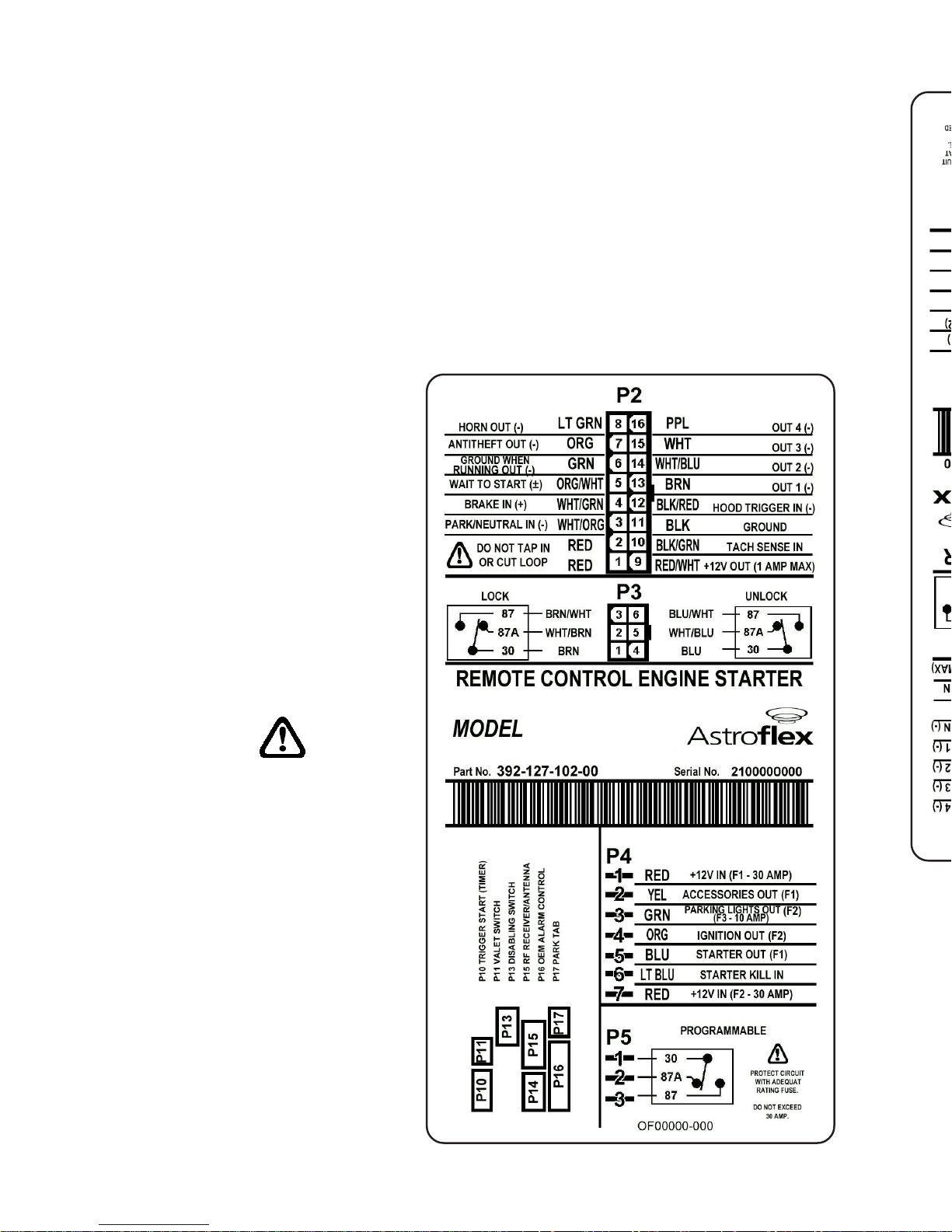
The following charts show the purpose of each wire on each connector and lists
the color code and pin position. Each of the first 5 charts are for a single connector . The last chart lists the connectors for the plug-in accessories.
Whenever you encounter a wire
that needs further explanation,
or need to access the virtually
unlimited programming flexibility of this Astrostart product, a
reference to the detailed installation instructions found later in
the manual will allow you to
understand all of the connection
and programming options
available. Additional information will be available on the
AstroChart CD ROM.
Each wire that provides a
(-) output can supply only
one single Bosch style
automotive relay.
2

P2 CONNECTOR (models 500, 1100, 2100, 4100)
Note: Programmable outputs #1 & #2 (P2-13 & 14) also appear on the P16
connector. If you need programmable outputs while P16 is being used with
different settings, use programmable outputs #3 & #4 instead (P2-15 & 16).
3
CONNECTEUR P2 (modèles 500, 1100, 2100, 4100)
Remarque : Les sorties programmables 1 et 2 (P2-13 et 14) se retrouvent
également sur la prise P16. Si vous avez besoins de sorties programmable et
que la prise P16 est utilisée avec des réglages qui diffèrent des sorties
programmables 1 et 2, utilisez plutôt les sorties programmable 3 et 4 (P2-15
et 16).
NIPEMANROLOCESOPRUP
1- deR!tucronipaTtoNoD-A/N
2- deR!tucronipaTtoNoD-A/N
3
/kraP
lartueN
tupnihctiwS
/etihW
egnarO
ebtsumti;ecivedytirucesafotrapsitiucricsihT.rotceteDytefaSlartueN/kraP
.tinuniamnobaTkraP71Potdetcennoc
4
ekarB
)+(
/etihW
neerG
tupnI tratsetomerlecnactupniotelcihevehtfotiucricthgilekarbehtotdetcennoc
tsum-TIUCRICYTEFAS.hctiwslecnaclortnocesiurcotnitcennoctonoD.noitarepo
!detcennoceb
5
rogulPwolG
tratSdeyaleD
)±(
/egnarO
etihW
tupnI leseid(gulpwolGlitnuedomybdnatsniniamerottratsetomerswolla
).ces06otpu(.flestistaeherp)enigne .)+(sitluafeD enigneeht,detcennocnutfelfI
.)3LEVELees-.ces03rofelbammargorp(.ces06retfatratslliw
6
)-(tuptuO
gninnurnehw
neergkraD
tuptuO noitingiehterofebs1detavitcA.secivedtfehtitnaMEOhtiwecafretniotdesu
.ffotuhssinoitingiretfas1litnusniamerdna,tiucric
7)-(tfehtitnAegnarO
tuptuO DELrotiucrictfehtitnanalortnocotdesu
.)41egapno"TUPTUOTFEHTITNA"ees(
8)-(nroHneergthgiL
.)005tpecxE( tuptuO nA.tuptuolevelwolasisihT.nrohyrotcafehtetavitcaotdesu
selcihevniatrecnoderiuqerebyamyalerlanretxe
)sliatedlannoitiddarof41egapees(
9V21+etihW/deR
tuptuO naybdetcetorP.)slioc(syalerlanoitiddarofstloV21+desufedivorpotdesu
)snoitacilpparetratSdn2ronoitingIdn2roftoN:etoN(A1fo)CTP(esufteserotua
01tupnihcaT
/kcalB
neerG
)langishcat(langisdeslupasedivorptahtelcihevnitiucricotdetcennoC
.MPR008,lyc1:tluafeD .snoitpognimmargorprof51egaPeeS
11dnuorGkcalBottcennoC.dnuorGniaM lenapkciktfel ro llawerifylno .
21
nipdooH
.O.N)±(tupni
.C.Nro
deR/kcalB
ytiralopelbammargorP tupni .doohehtfogninepotcetedotdesu
.nepodoohnehwdesolcyllamroN:tluafeD
!detcennocebtsum-TIUCRICYTEFAS.snoitpognimmargorprof61egaPeeS
31
-margorP
)-(elbam
1#tuptuo
nworB
evitageN tuptuo .trahcsihtwolebetoneeS.yalerlortnocot1#
tratSerofeBesluP:tluafeD .
.snoitpognimmargorprof71egaPeeS
41
-margorP
)-(elbam
2#tuptuo
/etihW
eulB
evitageN tuptuo .trahcsihtwolebetoneeS.yalerlortnocot2#
.tratSretfAesluP:tluafeD
.snoitpognimmargorprof71egaPeeS
51
-margorP
)-(elbam
3#tuptuo
etihW
evitageN tuptuo .yalerlortnocot3#
.esaeleRknurT:tluafeD
.snoitpognimmargorprof71egaPeeS
61
-margorP
)-(elbam
4#tuptuo
elpruP
evitageN.)005tpecxE( tuptuo .yalerlortnocot4#
.thgiLemoD:tluafeD
.snoitpognimmargorprof71egaPeeS
1- eguoR!repuocsapentenoitavirédederiafysapeN-A/N
2- eguoR!repuocsapentenoitavirédederiafysapeN-A/N
3
4
5
6
7
8
9V21+
01
11essaMrioN
21
31
41
51
61

NOTE: FOR ALL ABOVE WIRES PLEASE SEE PAGE 17 FOR FURTHER DET AILS
Note: The P3 Connector accesses two fully programmable Bosch style relays
that are intended for power door lock interface.
4
P3 CONNECTOR (models 1 100, 2100, 4100)
P4 CONNECTOR (models 500, 1100, 2100, 4100)
NIPEMANROLOCESOPRUP
103-nommoCnworB.)KCOL(yalerepythcsoBevitomotuadradnatsfo03niP
2a78-CNnworB/etihW.)KCOL(yalerepythcsoBevitomotuadradnatsfoa78niP
378-ONetihW/nworB.)KCOL(yalerepythcsoBevitomotuadradnatsfo78niP
403-nommoCeulB.)KCOLNU(yalerepythcsoBevitomotuadradnatsfo03niP
5a78-CNeulB/etihW.)KCOLNU(yalerepythcsoBevitomotuadradnatsfoa78niP
678-ONetihW/eulB.)KCOLNU(yalerepythcsoBevitomotuadradnatsfo78niP
«etnemilA.)1F(pma03edelbisufnurapeégétorp,V21+eértnE
.»écnofuelblif-ruerraméD«te»enuajlif-seriosseccA
edxuefsedtiucriceletnemilA.)3F(A01edelbisufnurapégétorP
edfitisopsidnu'deitraptiafeitrosetteC.egamulla'dtiucriceletnemilA
.elucihévudegarramédedtiucricud»ruerraméd«étôcudehcnarbeS
resilartuenedtemreP.»egamulla«lifelrapeédnammoctseeitrosetteC
ecnatsidàegarramédudtnemomuaelucihévudegarramédedtiucricel
emmoctnemelagéeésilitU.esirpneertne'nruerramédeleuqretivéruop
elucihévudegarramédedtiucricud»tcatnocedélc«étôcudehcnarbeS
.lovitnafitisopsidemmoctnemelagéeésilitU.)tnemelues0014,0012(
noitisopedxueF«te»egnarolif-egamullA«etnemilaiuqV21+eértnE
NIPEMANROLOCESOPRUP
1tupnirewoPdeR
seilppus,)1F(esufA03aybdetcetorp,tupnirewopV21+
."eriWeulBkraD-retratS"ehtdna"eriWwolleY-yrosseccA"
2
yrosseccA
tuptuo
wolleY.)tiucricCA/retaeH(tiucricyrosseccaelcihevsdeeF
3
gnikraP
tuptuothgil
neerG.tiucricthgilgnikrapdeefotdesu,)3F(esufA01aybdetcetorP
4
noitingI
tuptuo
egnarO
ti;ecivedytirucesafotrapsitiucricsihT.tiucricnoitingisdeeF tsum eb
detcennoc yltcerid .tiucricnoitingis'elcihevot
5
retratS
tuptuo
eulBkraD
.tiucric"retratS"elcihevotstcennoC
.)ylno0014dna0012-noitpollikretratS(
ybdellortnocsituptuosihT.tiucricrotomretratsfoedisretratsotstcennoC
sielcihevnehwffotuhsebottiucricretratsswollA.eriw"noitingi"eht
sedivorposlA.rotomretratseht"gnidnirg"tneverpotdetratsetomer
.noitcnuftfehtitna
6
-retratS
tuptuolliK
eulBthgiL
desuoslA.)ylno0014,0012(.tiucricrotomretratsfoedisyekotstcennoC
.edomtfehtitnArof
7tupnirewoPdeR
neerG-sthgiLkraP"ehtdna"eriWegnarO-noitingI"sdeefhcihwtupniV21+
.)2F(esufpmA03aybdetcetorP."eriW

P5 CONNECTOR (models 1 100, 2100, 4100)
The default is set for Ignition. (Level 13) Power supply for this circuit must be
protected with an appropriate fuse.
PLUG-IN ACCESSORIES CONNECTOR LIST
5
CONNECTEUR P5 (modèles 1100, 2100, 4100)
La valeur par défaut est réglée pour Allumage (niveau 13). L’alimentation de ce
circuit doit être protégée par un fusible de calibre assortie.
LISTE DES CONNECTEURS POUR ACCESSOIRES ENFICHABLE
ROTCENNOC
ROF
LEDOM
EMANESOPRUP
01PLLA
DETACIDED
REMIT
LORTNOC
eboteludomremitlanoitponagniwollarotcennocnip-ruoF
.)XELFORTSAmorfelbaliava(tratsetomerehthtiwdecafretni
tratsetomerezilaitiniot).ces7.0(eslupevitagenaseriuqeR
.erudecorp
11P00140012HCTIWSTELAV
telavrofdellatsniebothctiwsagniwollarotcennocnip-eerhT
.snoitcnuf
31PLLA
FFO/NO
HCTIWS
.ffosnoitcnuftratsetomerehtnrutotelbaebotdesuhctiwS
.syaler"retratsdnaseirossecca,noitingi"slortnoC
41P005
/KCOL
KCOLNU
ecafretni1-ALDaotyltceridtcennocotrotcennocnip-eerhT
:tluafeD.syalerevirdotstuptuotnerrucwolevitagenro,eludom
eeS.noitamrifnoCon,kcolotuAoN,eslupdnoces7.0elgniS
.snoitpognimmargorprof11egaP
51PLLA
/ANNETNA
REVIECER
/annetnaFRehtotniyltceridsgulptahtrotcennocnip-ruoF
.eludomreviecer
61PLLA
/MRALA
REZILIBOMMI
GNICAFRETNI
ELUDOM
XELFORTSAnaotyltceridtcennocotrotcennocnip-thgiE
.eludomgnicafretnirezilibommi/mrala
.)eludomehthtiwdegakcapsliatedrehtrufeeS(
71PLLABATKRAP
othctiwsrotcelesraegfonoitcetedgniwollarotcennocnip-owT
.raegnitratst'nowelciheverusne
NIPEMANESOPRUP
103-NOMMOCyalerepythcsoBevitomotuadradnatsfo03niP
2a78-CNyalerepythcsoBevitomotuadradnatsfoa78niP
378-ONyalerepythcsoBevitomotuadradnatsfo78niP
Quick Programming
Y ou may believe that a product as versatile as the AstroStart would be a programming nightmare. In most cases, you will not need to change from the factory
default programming. In addition, Astrostart’s sophisticated processor allows
direct entry into a multitude of programming options with little effort.
All programming is performed through a 9 button DIP switch module. The
programming options for any feature are presented in the individual feature
explanation, which means there is no need to refer to a confusing but comprehensive master programming chart.
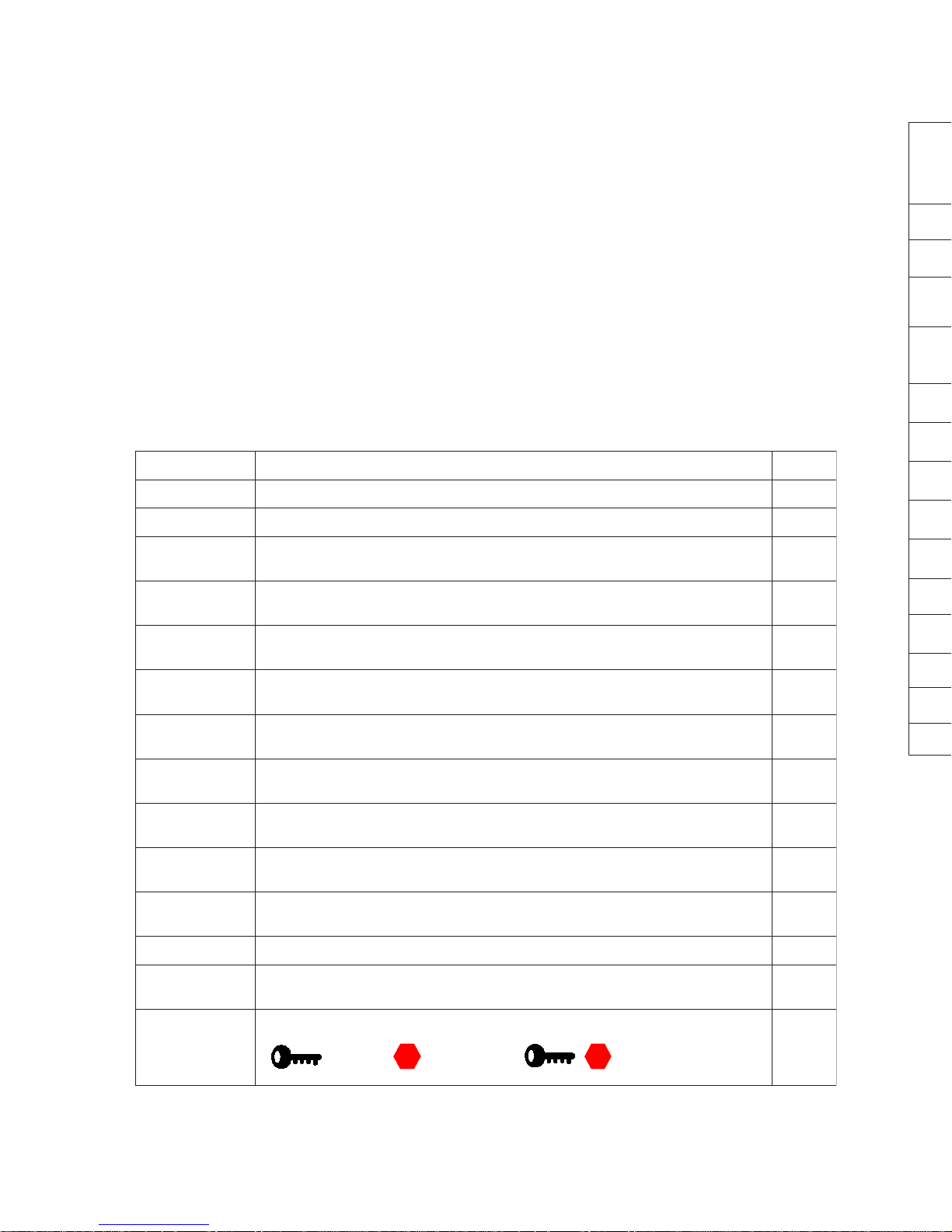
Will I Need To Reprogram a Feature?
Consult the following chart to determine if the defaults work for the installation. If
this chart reveals no required changes, move to the testing phase of the installation on page 21.
If changes to the default programming are required, please become familiar with
the following information in the programming charts.
6
1
udruetpurretni-egarramédedselcycselertneépuocegamulla-ecnesseàruetoM
3
lovitna-noitcnofsrohtnememraér-egarramédsèrpaseriossecca'dialédedsaP
4
-.ces7,0edegalliuorrev/édednoislupmI,.ces7,0edegamullAtnavAnoislupmI
ednoitamrifnoc-elpmis=egalliuorrevédednoislupmi-noitcnofsrohegalliuorrevotua
01
udeérud-.ces7,0ed2oneriatilitunoislupmi-.ces7,0ed1oneriatilitunoislupmI
.)tnemeluessnotuob6àednammocélét-noitcnofne(.ces03ed»euqinap«edom
11
8=ecnesse:ehcramedspmet-)F°5(C°51=ellenitnesedomuderutarépmeT
31
)FFO/NO(ELLENITNESTÊRRAEGARRAMÉD
51
CIPOTDELLORTNOCSERUTAEFTLUAFED LEVEL
srettimsnarT .denraelebtsumsetomerlanoitiddasselnuderetlaton-elbanEetomeR 1
enignE/hcaTdeepseldiMPR008,rednilyc1 2
enignE
noitarugifnoC
tcatnocdesolchctiwsdooH,selcycknarcneewtebffotucnoitingI,elcihevenilosaG
.neposidoohnehw
3
tfehtitnA
ytilibitapmoC
ffotfehtitnA,ffognimraeR,putratsretfayaledyrosseccaoN 4
elbammargorP
stuptuO
)1#tuptuoelbammargorp(erofebesluP 5
elbammargorP
stuptuO
)2#tuptuoelbammargorp(retfaesluP 6
elbammargorP
stuptuO
)3#tuptuoelbammargorp(knurT 7
elbammargorP
stuptuO
)4#tuptuoelbammargorp(thgilemoD 8
elbammargorP
yaleR
)yalerelbammargorp(noitingI 9
kcoLrooD
snoitpO
-eslupgnikcolnU,ffokcolotuA,eslupkcolnu/kcol.ces7.0,noitingIerofebeslup.ces7.0
ffonoitamrifnoceslupgnikcoLdn2,elgnis
01
stuptuOytilitU
noitarudcinaPdnoces03,2#eslupytilitudnoces7.0,1#eslupytilitudnoces7.0
)ylnosetomernottub6-nO(
11
emiTnuRenignEemitnur.nim61-leseiD,.nim8-enilosaG 21
pmeTlenitneS
emiTnuR&
leseidnim61-,sagnim8-lenitnesemitnuR,)Fº5(Cº51-erutarepmetedomlenitneS 31
setomeRnottuB-2
)ylno205ledom(gnidocedrettimsnartetomernottuB-2
)ffo/no(LENITNES=POTS=TRATS=
51
 Loading...