

ASTRODYNE ASL365 Service Manual
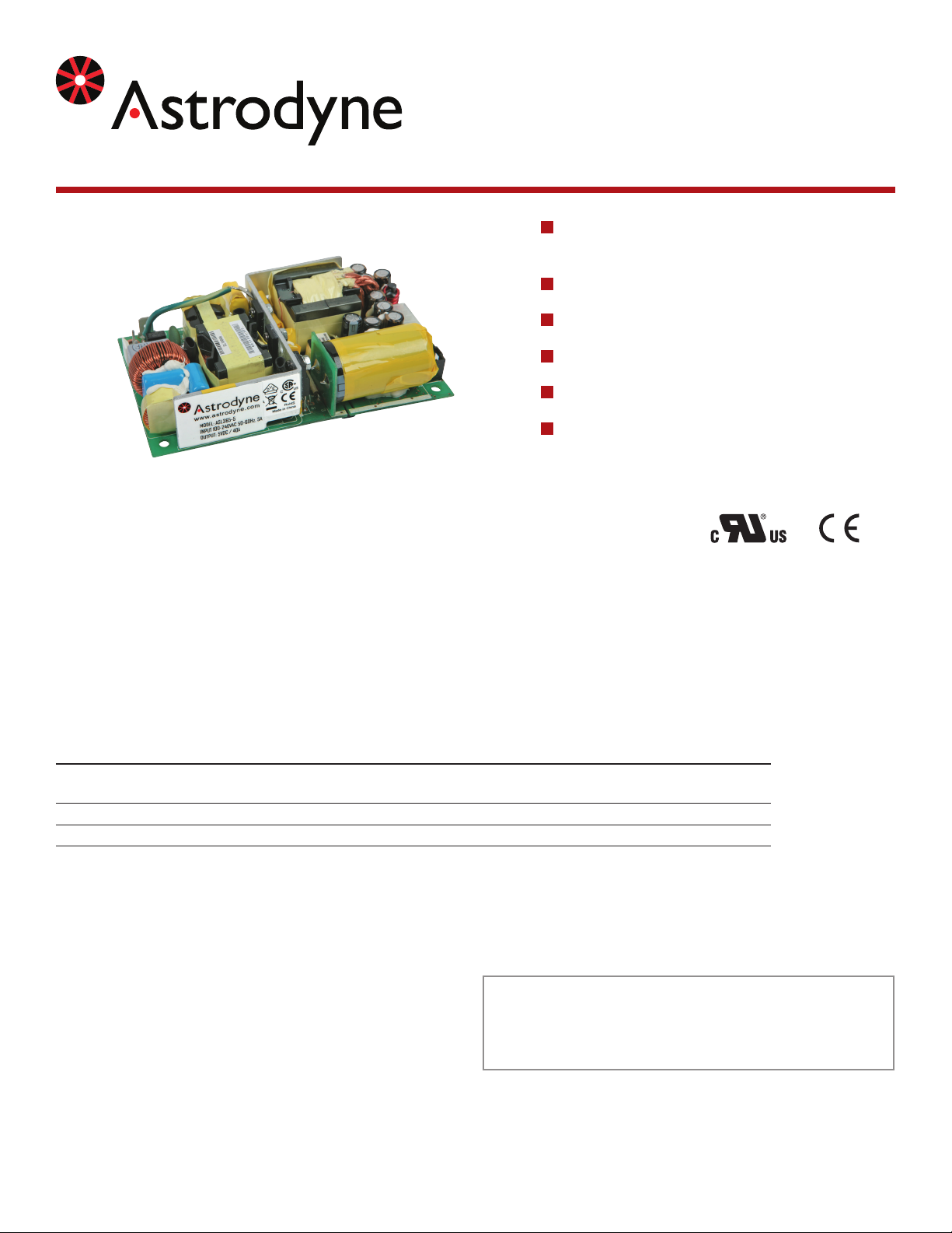
365W High Density PFC Switcher with 12V aux & 5V Stand By
A S L 3 6 5 s e r i e s
Single Outputs with 12V Auxillary and 5 Volt
Stand By
Universal 90 to 264VAC Input
18W/in3 Power Density
12VDC to 48VDC Outputs
3,000VAC Input to Output Isolation
Short Circuit Protection
3” x 5” x 1.28”
This specication describes an open frame 365W forced air / 200W convection cooled power supply that provides
three independent direct constant voltage outputs, one of which may be congured as a stand by power supply (5V)
powered from an external main AC source or UPS and utilizes an active PFC (Power Factor Correction) topology
in an industry standard 3” x 5” x 1.28” package. Also included is a 12V auxilary output suitable for driving a fan. The
supply shall meet the requirements (80-Plus) of the Energy Star 4.0 document and the anticipated 90+ requirement
for 2010. The supply is also RoHS/WEEE compliant.
Model Number O/P VDC Iout (Convection / 200LFM) 12V aux. 5VSB (5 Volt Stand By) OVP
ASL365-12 12VDC 16.6 / 30.4A 0.5 / 1A 1 / 2A 13.2-15V
ASL365-24 24VDC 8.3 / 15.2A 0.5 / 1A 1 / 2A 26.4-30V
ASL365-48 48VDC 4.16 / 7.6A 0.5 / 1A 1 / 2A 52-60V
Astrodyne products are not authorized or warranteed for use
as critical components in life support systems, equipment used
All specications are typical at nominal input, full load, and 25DegC unless
otherwise noted
WWW.ASTRODYNE.COM
in hazardous environments, nuclear controls systems, or other
mission-critical applications.
ASTRODYNE USA: 1-800-823-8082
ASTRODYNE PACIFIC: 886-2-26983458

365W High Density PFC Switcher with 12V aux & 5V Stand By
A S L 3 6 5 s e r i e s
INPUT SPECIFICATIONS
Input Voltage Range 90-264VAC
Harmonic Input Current EN61000-3-2
(230V/50Hz; 100V/50 or 60Hz)
Input Current FL <5A @ 90VAC; <2.5A @ 180VAC
Input Power Rating <430 Watts
Inrush Current 53A @ 110V; 116A @ 220V, typ.
Efciency 90%, typ.
Input Frequency 47-63Hz
Power Factor (90VAC) 0.98% min.
Under Voltage Lockout No Damage
Transients IEC61000-4-4 Level 3
IEC61000-4-5 Level 3
Leakage Current (115/230 I/P) 110/275uA
OUTPUT SPECIFICATIONS
Voltage Adjust ±5% Main Output typ.
Load Regulation Main O/P: ±1% max.; all others ±5%
Line Regulation ±1% High Line to Low Line
Tolerance Main O/P: ±3%
5VSB: ±5%
12V aux.: ±15%
Transient Response
(50% Load Change) 10% Recover within 1mS
Start Up 5VSB: 700mS, typ.
All other outputs: 500mS, typ.
Hold Up Main O/P: 20mS. typ.
5VSB: 2S, typ.
Rise Time 5VSB: 0.7S
All Other Outputs: 20mS max.
Overshoot (Power On/Off) Vout x 1.1; 50mS max.
Ripple/Noise (Note 1) 12V aux: 2% of Output
All other outputs: ±1%
Short Circuit Auto Recovery; No Damage *
Over Current Protection 150%, Auto Recovery
Over Voltage Protection (OVP) 5VSB: 5.5-6.8V
Main O/P: See Model Selection Chart
Remote Sense <250mV drop compensation
PS Enable PS is off until enable signal
(TTL or Ground) is applied
DC OK Signal goes TTL high to indicate DC
WWW.ASTRODYNE.COM
regulation
5V Standby (5VSB) 2A current always on when AC input
is present
12V Auxilary 1A current to power cooling fan(s)
GENERAL SPECIFICATIONS
Isolation I/P-O/P 3000VAC 1 Minute
Safety Standards UL/cUL 60950
Size 3” x 5” x 1.28”
ENVIRONMENTAL SPECIFICATIONS
Oper. Temperature -20 to +50°C (See Derate Curve)*
Max. Heatsink Temperature 110°C @ 50°C ambient
Cooling 200LFM >200W O/P Power
Relative Humidity 95% Non Condensing
Storage Temperature -40 to +80°C *
Operating Altitude 5KFT ASL, derated to 40°C @ 10KFT
Shock 10G, 11mS Half Sine, 3 Axis
Vibration 0.5G, 10-300Hz, 3 Axis
MTBF >250,000 Hrs, 75% Load, 35°C
EMI/EMC EN55022:1998 (CISPR22 Class B Conducted)
Voltage Fluctuation EN61000-3-3
ESD EN61000-4-2, 15KV Air, 8KV Contact
Radiated Field EN61000-4-3, 3V/m, 80-1000MHz
80% Modulated; 3M distance
EFT EN61000-4-4, 2kV on AC port for
1 minute ±1kV on signal/ctrl lines
Surge EN61000-4-5, ±1kV line to line;
±2kV line to earth
Conducted RF EN61000-4-6, 3Vrms, 0.15-80MHz
80% Modulated
Voltage Variations EN61000-4-11: >95% dip, 0.5 period
30% dip. 0.25 period
>95% reduction, 250 periods
Harmonic Current Emissions IEC61000-3-2 Class D
Note 1: O/P Noise measured directly at the pins/terminals at nominal
load with a 0.1uF bypass and 47uF electrolytic capacitor; pk-pk @
20MHz bandwidth.
* These are stress ratings. Exposure of the devices to any of these conditions
may adversely affect long term reliability. Proper operation under conditions
other than the standard operating conditions is neither warranteed nor implied.
ASTRODYNE USA: 1-800-823-8082
ASTRODYNE PACIFIC: 886-2-26983458
 Loading...