

Page 1

HD LCD WAVEFORM MONITOR
WM-3209/WM-3209-L/
WM-3209-B
Instruction Manual
Ver.3.00
Page 2

Page 3

HD LCD WAVEFORM MONITOR
WM-3209/
WM-3209-L/
WM-3209-B
Instruction Manual
2010.11
Ver.3.00
ASTRODESIGN,Inc
Page 4

Page 5

i
Contents
Contents........................................................................................................................................ i
Introduction ................................................................................................................................. iv
Safety Precautions...................................................................................................................... iv
Concerning the Unit................................................................................................................. iv
Concerning the Power Cord........................................................................................................ iv
Concerning the Foreign Matter ....................................................................................................v
Concerning the the Battery .......................................................................................................... v
Concerning the Power Supply.....................................................................................................vi
Concerning the Liquid Crystals ................................................................................................... vi
Concerning the Shock of Impact .................................................................................................vii
Concerning the Installation and Operating Locations..................................................................vii
Concerning the Phenomena Related to Liquid Crystal Performance ......................................... viii
Chapter 1
Concerning the WM-3209/WM-3209-L ............................................................................................ 1
WM-3209/WM-3209-L Overview.................................................................................................. 1
Chapter 2 Names of Parts................................................................................................................................ 3
2.1 WM-3209/WM-3209-L Front Panel and Names of Parts ................................................... 3
2.2 WM-3209/WM-3209-L Rear Panel and Names of Parts.................................................... 5
Chapter 3 Method of Operation...................................................................................................................... 11
3.1 Connections .................................................................................................................... 11
3.2 Method of Operation........................................................................................................ 12
3.3 Switch Specifications.......................................................................................................13
3.3.1 INPUT Switch........................................................................................................13
3.3.2 COLOR Switch......................................................................................................14
3.3.3 FREEZE Switch .................................................................................................... 15
3.3.4 U1 through U4 Switches .......................................................................................15
3.3.5 Preset Switch ........................................................................................................ 15
3.3.6 MENU Switch........................................................................................................ 15
3.3.7 ESC Switch...........................................................................................................15
3.3.8 F1 through F5 Switches ........................................................................................ 16
3.3.9 Mode Switches...................................................................................................... 16
3.4 Description of the MENU Screens................................................................................... 17
3.4.1 MENU Screen Details (Basic Operations)............................................................. 17
3.4.2 INPUT CHANNEL ................................................................................................. 21
3.4.3 ID SETTING.......................................................................................................... 22
3.4.4 COMPARE............................................................................................................ 24
3.4.5 PICTURE QUALITY..............................................................................................30
3.4.6 MARKER ..............................................................................................................31
3.4.7 DISPLAY............................................................................................................... 34
3.4.8 TALLY ................................................................................................................... 36
3.4.9 PICTURE .............................................................................................................. 39
3.4.10 WAVE....................................................................................................................41
3.4.11 VECTOR ............................................................................................................... 43
3.4.12 AUDIO ..................................................................................................................44
3.4.13 SWITCH ASSIGN ................................................................................................. 46
3.4.14 REMOTE ASSIGN ................................................................................................49
3.4.15 LOAD & SAVE ...................................................................................................... 54
3.4.16 HARDWARE SETTING.........................................................................................56
3.4.17 RESET CALL ........................................................................................................ 59
Chapter 4 Description of Each Mode .............................................................................................................61
CH ID 62
Level meter...........................................................................................................................62
Format information ...............................................................................................................62
F1 to F5 switches ................................................................................................................. 62
Input status information ........................................................................................................ 62
Error information................................................................................................................... 63
Time code.............................................................................................................................64
Page 6

ii
4.1 Preset Mode....................................................................................................................65
4.2 Picture Mode 1 ................................................................................................................ 69
4.3 Picture Mode 2 ................................................................................................................ 71
4.4 Waveform Mode..............................................................................................................73
4.5 Vector Mode....................................................................................................................79
4.6 Status Mode .................................................................................................................... 81
4.7 Audio Mode ..................................................................................................................... 90
4.8 Phase Compare Mode ....................................................................................................92
4.9 Ancillary Display Mode.................................................................................................... 95
4.9.1 Multiplexed Packet Check Mode...........................................................................96
4.10
Multimode........................................................................................................................ 99
4.10.1 Multimode 1 ........................................................................................................101
4.10.2 Multimode 2 ........................................................................................................103
4.10.3 Multimode 3 ........................................................................................................106
4.10.4 Multimode 4 ........................................................................................................108
4.10.5 Multimode 5 ........................................................................................................ 110
4.11
Option Mode.................................................................................................................. 112
4.11.1 Option Mode 1 .................................................................................................... 113
4.11.2 Option Mode 2 .................................................................................................... 115
4.12
Compare Mode 1........................................................................................................... 118
4.12.1 Compare Mode 1 Overlap Display ...................................................................... 120
4.12.2 Compare Mode 1 Vertical Display.......................................................................127
4.13 Compare Mode 2........................................................................................................... 128
4.13.1 Compare Mode 2 Horizontal Display...................................................................130
4.13.2 Compare Mode 2 Vertical Display.......................................................................132
4.14 Compare Mode 3........................................................................................................... 134
4.14.1 Compare Mode 3 Horizontal Display...................................................................136
4.14.2 Compare Mode 3 Vertical Display.......................................................................139
4.15 Compare Mode 4........................................................................................................... 142
4.15.1 Compare Mode 4 Horizontal Display...................................................................144
4.15.2 Compare Mode 4 Vertical Display.......................................................................147
4.16 Compare Mode 5........................................................................................................... 150
4.16.1 Compare Mode 5 Horizontal Display...................................................................152
4.16.2 Compare Mode 5 Vertical Display.......................................................................155
Chapter 5
Specifications ..............................................................................................................................159
5.1 Input format ................................................................................................................... 159
5.2 Input Signal System ......................................................................................................161
5.3 Display Method .............................................................................................................162
5.4 Headphone Output Format............................................................................................ 162
5.5 Adjustment Values.........................................................................................................163
5.6 Aspect Ratio..................................................................................................................166
5.6.1 When Using a 4:3 Aspect Ratio ..........................................................................167
5.6.2 When Using a SCOPE Function .........................................................................168
5.6.3 When Using a 16:9 Aspect Ratio ........................................................................168
5.6.4 When Using a ×2 Function.................................................................................. 169
5.6.5 When Using a ×4 Function.................................................................................. 169
5.7
Audio Level Meter .........................................................................................................170
5.7.1 Audio Level and Cell Color Scheme ................................................................... 170
5.7.2 Display Format and Cell Color Scheme .............................................................. 172
5.7.3 Various Settings of the Audio Level Meter........................................................... 175
5.8
Scan Area...................................................................................................................... 178
5.9 Concerning the Dual Link Input Settings ....................................................................... 180
5.10 Concerning the Selection of Input Channels During External Control (contact power
supply)...........................................................................................................................183
5.11 Concerning the Dummy Composite Waveform Display................................................. 184
5.12 Concerning the Magnification Auxiliary Line for the Vector Waveform .......................... 185
5.13 Concerning the Phase Difference Alarm Function.........................................................187
5.14 Concerning the Arrangement of Brightness Values on the Grayscale...........................190
5.15 Concerning the Video Image Display in Compare Mode............................................... 192
5.16 Concerning the Low-Power-Consumption Mode........................................................... 201
5.17 Concerning the Flash Protect function ..........................................................................204
5.18 3D image parallax check ............................................................................................... 210
5.19 Concerning 3D image alignment ................................................................................... 212
5.20 Concerning checking 3D image using the anaglyph system ......................................... 214
5.21 Concerning the brightness difference display function .................................................. 216
Page 7

Contents
iii
5.22 Factory Default Settings ................................................................................................ 218
Common Setting Items (MENU Items) ...............................................................................218
Common Setting Items (items used in each mode)............................................................223
Common Setting Items (items used in COLOR adjustment mode) ....................................228
Setting Values by Channel (MENU Items)..........................................................................229
Setting Items by Channel (Items for Each Mode) ............................................................... 231
5.23
General Specifications...................................................................................................232
5.24 External View ................................................................................................................233
Chapter 6 Supplied Accessories and Options .............................................................................................. 236
6.1 Supplied Accessories .................................................................................................... 236
Chapter 7 Maintenance, etc. ........................................................................................................................ 238
For Improved Operability ......................................................................................................... 238
If the Unit is not Functioning Normally .....................................................................................240
If an Error or Malfunction Occurs ............................................................................................. 241
Page 8

iv
Introduction
Thank you very much for purchasing the HD LCD WAVEFORM MONITOR WM-3209/WM-3209-L.
This manual describes the operating procedure and precautions for using the WM-3209/WM-3209-L.
Mishandling the WM-3209/WM-3209-L may lead to accidents, so please be sure to read this manual in
order to operate the WM-3209/WM-3209-L correctly.
After reading this manual, please keep it in an accessible place for future use.
Safety Precautions
WARNIN
G
Concerning the Unit
Do not apply strong impact or throw the unit. Doing so may result in
leakage of liquid crystals, damage to the unit, explosion, overheating, or
fire.
Do not use the unit in a location where there is risk of catching fire or
explosion.
High-voltage parts are contained inside the unit. Do not disassemble,
repair, or modify the unit as there is a risk of electric shock or burn injury
as well as possible damage to the unit.
If you hear thunder while using the unit outdoors, immediately turn the
power off, disconnect the power cord from the unit, and move to a safe
location.
Concerning the Power Cord
Always grasp the power cord by the plug when disconnecting.
Do not forcibly bend or twist the power cord during use. This may result in
a fire hazard.
Do not place heavy objects on the power cord. This may lead to damage to
the cord resulting in fire hazard or electric shock.
Page 9

Introduction
v
Concerning the Foreign Matter
Do not drop liquid, flammables and metal objects inside this unit. Using
this unit in such a condition will cause fire, electric shock or failure.
Concerning the the Battery
Be sure to connect the battery with the correct polarity (+, -). Incorrect
connection will result in fire hazard, personal injury, and contamination of
the surrounding area due to the battery exploding or leaking.
Page 10

vi
CAUTION
Concerning the Power Supply
This unit uses a 10 to 18 V ±5% power supply.
To prevent damage to the unit and/or malfunction, we recommend that you
use the supplied AC/DC adapter. If you do use some other power supply
for some reason, be sure to pay attention to the supply voltage and
polarity.
After turning the power off, do not immediately turn the power on again.
This may lead to damage to the unit.
Note that use of the same DC power supply for audio components such as
a microphone, amplifier, and/or speakers may adversely affect audio
quality.
Concerning the Liquid Crystals
Sometimes there may be unresponsive pixels (always lit or always unlit)
due to performance of the liquid crystal display.
Do not touch liquid crystals if they leak from the liquid crystal panel.
If the liquid crystal panel is accidentally broken and the fluid (liquid crystals) inside leak out, do not
ingest, allow in the mouth, or allow in contact with the skin.
If liquid crystals do somehow get into your eyes or mouth, immediately
flush with water. If liquid crystals come in contact with skin or clothes,
immediately wipe the crystals off with alcohol and wash with soap.
Allowing liquid crystals to remain in contact may result in damage to skin
and/or clothing.
Handle broken liquid crystal panel glass with care.
If the liquid crystal panel breaks, take great care not to cut your hands on the glass shards.
Touching broken glass shards may result in injury.
The liquid crystal panel is an extremely high-precision instrument. Handle
the panel with care in regards to the points listed below.
• Wiping with benzene, thinner, or other alcohol-based solvent may result in deformation.
• If water (saline) is allowed to dry on the liquid crystal panel, it may result in change in color or
staining.
• Extended direct exposure to ultra-violet light may lead to loss of display quality due to browning
of the deflection plate and reduced contrast.
• Discoloration may result if water due to condensation or other cause gets inside the liquid
crystal panel.
Page 11

Introduction
vii
• Directly hitting or striking the liquid crystal panel may result in cracking.
• Do not disassemble the liquid crystal panel as it is dangerous if liquid crystals leak and get on
the skin.
Handle the liquid crystal panel with care.
If fingerprints or other soiling gets on the liquid crystal protective panel, wipe clean with a cleaner
intended for use with office equipment. Wiping forcefully may lead to scratching or damage to the
protective panel.
Concerning the Shock of Impact
Because this product is a precision device, applying shock to it may cause
damage. Be extra careful when moving this unit. Take great care when
moving the unit.
Do not drop the unit.
Concerning the Installation and Operating Locations
Installing this unit in the following locations may cause failure or accident.
• Locations where the ambient temperature of this unit will exceed the range of 0 to 40°C (Note
1)
• Locations where the ambient humidity of this unit will exceed the range of 30 to 80%RH
• Locations close to air conditioning equipment where sudden temperature change or dew
condensation occurs
• Locations exposed to direct sunlight (Note 2)
• Locations filled with corrosive gas or dust
• Locations where strong magnetic fields are formed
• Locations that may receive sprays of water, oil, chemicals, etc.
• Locations where vibrations may be transmitted from the floor
• Unstable locations
Make sure that the conditions below are satisfied to ensure normal use of
the unit.
• Do not place heavy objects such as a monitor on top of the unit.
• Avoid placing objects around the unit.
Note 1: There is a risk of damage to the backlight or other hardware if the temperature of the
surface of the liquid crystal panel exceeds 60°C.
Note 2: Extended direct exposure to ultra-violet light may lead to loss of display quality due to
browning of the deflection plate and reduced contrast.
Page 12

viii
Concerning the Phenomena Related to Liquid Crystal Performance
The following conditions may result due to liquid crystal performance.
The response time, brightness, and color of liquid crystals may vary due to
ambient temperature.
Depending on the contents of the display, variations in brightness, flicker,
vertical stripes, and/or minute spots may be visible.
Optical characteristics (brightness, variations in display, etc.) vary
depending on the operating time. These characteristics particularly vary
due to low temperatures.
Variations in the display color may occur depending on the viewing angle.
Noise may occur on the startup screen.
A residual image may occur. Avoid displaying a stationary pattern for an
extended period of time.
There is a possibility of screen burn-in if a stationary pattern is displayed
for an extended period of time.
Page 13

1
1
1
Concerning the
WM-3209/WM-3209-L
The WM-3209/WM-3209-L is a compact, light-weight, versatile LCD waveform monitor intended for
monitoring video images from a OB van or in the studio.
Video images, waveforms, and audio signals may be monitored from locations where it has been difficult to
transport equipment.
The space required for installation has been reduced by incorporating the capabilities of a picture monitor and
waveform monitor into a single unit.
In terms of its input signals, the waveform monitor supports 21 3G TV video formats, 21 HDTV video formats
and two SDTV video formats. It also supports Dual Link inputs.
The model supports monitoring while stereoscopic image are being taken and, using the anaglyph
stereoscopic system*, it is possible to check 3-dimensional images and measure the differences in the
brightness between the left and right images.
The dual link input signals support 13 HDTV formats.
The ID display can be controlled from an external remote controller (PC). (WM-3209-L only)
(*) Separate special eye-glasses are required to view the images provided by this system.
WM-3209/WM-3209-L Overview
Incorporates an 8.4-inch a-Si TFT liquid crystal panel
Wide range of different video formats supported
3G-SDI-compatible standard: Conforms to SMPTE 425M standard (2.97 Gbit/s SDI input)
HD-SDI-compatible specifications: Conforms to SMPTE292M and BTA S-004B specifications
(1.485 Gbit/sec SDI input)
Dual Link-compatible standard: Conforms to SMPTE 372M standard (1.485 Gbit/s SDI input,
2 systems)
The 1080p60, 1080p60/1.001 and 1080p50 formats are not
supported.
SD-SDI-compatible specifications: Conforms to SMPTE259M specifications
(270 Mbit/sec SDI input)
Composite input (NTSC: Conforms to SMPTE170M, PAL: Conforms to part of
ITU-R. BT624-4)
* Cable extension up to 100 meters is possible for the SDI inputs.
For the 3G SDI signals, use the Belden 1694A 100-meter cable or its equivalent.
Includes connectors for SDI IN (2 channels), SDI MONITOR OUT (2
channels), and composite input (NTSC and PAL)
* When composite signals are input, waveforms of component signals that are converted from
the input signals are displayed.
8 bit composite input resolution due to decoder performance. Furthermore, when supplying a
PAL signal, the waveform is distorted beyond reality for the three lines at the start and end of
the video signal.
Various Video Adjustment Functions
Brightness adjustment function (G, B, and R can be adjusted independently) ±50%
Contrast adjustment function (G, B, and R can be adjusted independently) 0 to 200%
Chroma level adjustment function 0 to 200%
Independent R-B-G ON/OFF function
Page 14

2
Peak function 0 to 100
Hue adjustment function -179 to 180°
Chroma signal OFF function
Chroma up function
Gamma adjustment function (G, B, and R can be adjusted independently) 1.00 to4.00
Maker display
Center marker, frame marker, and safety marker (95%, 93%, 88%, 80%)
Down converter marker (4:3, 13:9, 14:9)
Cinema marker (2.35:1 Cinemascope, 1.85:1 Cinema Vista, 1.66:1 Euro Vista)
User-variable marker, BOX marker, and grid marker
One-touch switches can be customized to the user’s taste.
Dummy composite waveform displays supported
Includes top-bottom reverse display
Includes multi-display modes
Picture, waveform, vector, status, audio level meter, audio vector mode, phase comparison mode,
ancillary display mode, multi-display, and compare mode
Includes compare modes
The unit can display comparisons between the current display and frozen images, other input
signals, or images stored in memory.
Includes a 4-system phase difference display function and alarm function
The phase difference of the two input signal systems (HD-CS, BB)and two external reference
systems can be simultaneously displayed. Furthermore, an alarm display is available by setting a
phase difference versus the input signal (phase comparison mode).
Includes stereoscopic image check function (anaglyph)
Three-dimensional viewing of stereoscopic images is now possible using the anaglyph
stereoscopic system. It is also possible to measure the differences in the brightness between the
left and right images (compare mode 1).
External control (contact power supply system) for lighting the tally lamp,
loading preset data, and other functions is possible.
External control (from a PC or other controlling device) of the ID display is
possible (WM-3209-L only)
Includes preset function (loading and saving of up to 8 preset data
possible)
Automatic tracking of the input signal
Automatic tracking of the frame rate (1/1.000 and 1/1.001) and input signal
detection function
Input channel CRC error detection function (for HD-SDI input)
Time codes (VITC, LCT and time codes for users) displayed (with SDI
input)
Panel lock and setting value saving function
Slimline, light-weight
12 V DC-compatible (10 to 18 V)
Page 15
3
2
2
Names of Parts
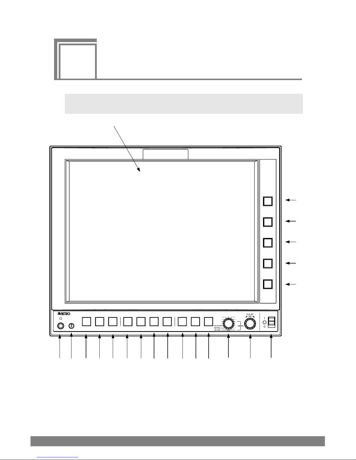
2.1 WM-3209/WM-3209-L Front Panel and Names of
Parts
Figure 2.1 WM-3209/WM-3209-L Front Panel
(6)
(4)
U3
HD LCD WAVEFORM MONITOR WM-3208
L.ADJ
INPUT COLOR FREEZE U1 U2 PRESETU4 MENU ESC
AUDIO
PHASE
VECTOR
STATUS
ANC
3
4
5
OPTION
MULTI
1
2
POWER
F 5
F 4
F 3
F 2
F 1
(5) (7) (8) (9) (12) (13) (14) (15) (16) (10) (11) (3) (2) (1)
(21)
(20)
(19)
(18)
(17)
Page 16
4
Table 2.1 Front Panel Part Names
Number Name Description
(1)
POWER Switch/LED
Turns power ON/OFF.
When POWER is ON: Lights green
During KEY LOCK: Lights orange
(2)
Adjustment dial
Adjusts and selects setting values
(3)
Mode switch
Switches the mode. The mode is switched as follows.
PRESET, PICTURE1, PICTURE2, WAVEFORM, VECTOR, STATUS,
AUDIO, PHASE, ANC, MULTI, OPTION, COMPARE1, COMPARE2,
COMPARE3, COMPARE4, COMPARE5
(4)
Headphone jack
Outputs audio. (φ35 mm) (*1)
(5)
Adjustment dial
Adjusts the liquid crystal backlight (*2)
(6)
Liquid crystal display
Displays video images.
(7)
INPUT switch
Switches the input channel.
(8)
COLOR switch
Displays a screen for setting color information. Pressing the same button
again exits the color setup screen.
Items that can be set include: Information, Marker, Cursor, Scale, Waveform,
Vector, Audio Vector and Status.
(9)
FREEZE
Freezes the on-screen image.
(10)
MENU switch
Displays the MENU screen. Pressing the same button again exits the color
setup screen.
Pressing and holding the switch locks the front switch.
Repressing and holding the switch unlocks the front switch.
In accordance with the main unit function settings (*3), the settings are
automatically saved in BOOT of the memory at the same time as key lock is
initiated.
(11)
ESC
Exits the setup screen.
If pressed while saving or clearing picture memory, that operation is
canceled.
(12)
U1
User-assigned switch
(13)
U 2
User-assigned switch
(14)
U 3
User-assigned switch
(15)
U 4
User-assigned switch
(16)
PRESET switch
Saves preset data and displays a call-up screen. Pressing the same button
again exits the color setup screen.
(17)
F1 switch
The function assigned to this switch varies depending on the mode.
(18)
F2 switch
The function assigned to this switch varies depending on the mode.
(19)
F3 switch
The function assigned to this switch varies depending on the mode.
(20)
F4 switch
The function assigned to this switch varies depending on the mode.
(21)
F5 switch
The function assigned to this switch varies depending on the mode.
*1: If a embedded audio is multiplexed with the SDI signal, an audio signal is output.
*2: A ripple voltage of approximately 300Hz may arise in the DC power input when brightness is lowered using the
backlight adjustment dial.
*3: For further details, refer to chapter 3 "3.3.6 MENU Switch."
Page 17

Chapter 2 Names of Parts
5
2.2 WM-3209/WM-3209-L Rear Panel and Names of
Parts
ASTRODESIGN,Inc.
MADE IN JAPAN
COMPOSITE IN
BB
REMOTE
HD_CS
A B
B1
B2A2
A1
DC IN 12V
1 GND 4 +12V
MONITOR
OUT
REF.IN
SDI IN
RS485
Figure 2.2 WM-3209 Rear Panel
②
⑥
③
⑧
①
⑤
④
⑨
⑦
⑪
⑩
Page 18

6
DC IN 12V
ASTRODESIGN,Inc.
1 GND 4 +12V
MADE IN JAPAN
COMPOSITE IN
BB
REMOTE
REF.IN
MONITOR
HD_CS
A B
OUT
B1
B2A2
A1
SDI IN
RS485
Figure 2.3 WM-3209-L Rear Panel
⑧
②
⑥
③
①
⑤
④
⑨
⑦
⑪
⑩
⑫
Page 19
Chapter 2 Names of Parts
7
Table 2.2 Rear Panel Part Names
Number Name Description
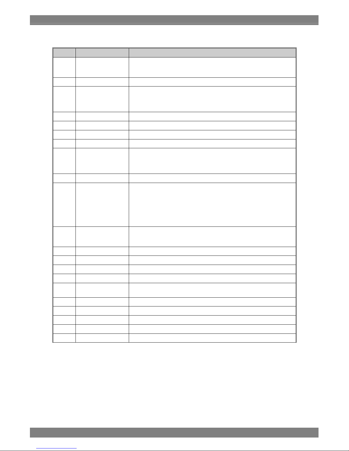
(1) Power connector (*1) This is a XLR connector DC power input terminal. (GND: Pin 1, DC IN: Pin 4)
(2) SDI IN A1ch (*2) This is the Link signal input connector for the 3G-SDI, HD-SDI, SD-SDI and
dual link signals.
(3) SDI IN A2ch This input connector is not provided.
(4) SDI IN B1ch (*2) This is the Link signal input connector for the 3G-SDI, HD-SDI, SD-SDI and
dual link signals.
(5) SDI IN B2ch This input connector is not provided.
(6) MONITOR OUT A This output terminal is for easily checking the SDI input signal.
(7) MONITOR OUT B This output terminal is for easily checking the SDI input signal.
(8) COMPOSITE IN This is the composite input terminal.
(9) REF IN (HD_CS) This is the reference input terminal.
(HD 3-value sync signal)
(10) REF IN (BB) This is the reference input terminal.
(NTSC/PAL black burst signal)
(11) REMOTE (*3) D-sub 15-pin (female) for connect and control
(12) RS485 (*4) Two RJ45 8-pin (female) terminals for RS485 control
One terminal is used for control signal input. When a terminal is used for
control signal input, the other is used as a through-output terminal.
(WM-3209-L only)
*1: POWER connector (Number (1))
Pin No. Description
1 GND
2 NC
3 NC
4 DC IN (10-18 V)
1
2 3
4
Page 20
8
*2: SDI IN A 1ch to SDI IN B 2ch (Number (2) and (4))
When Dual Link1 has been selected as the input channel, input the Link A signals to the SDI A1 connector and
the Link B signals to the SDI B1 connector.
For details on the dual link inputs, refer to “5.9 Concerning the Dual Link Input Settings.”
For details on selecting the input channel, refer to “3.4.2 INPUT CHANNEL.”
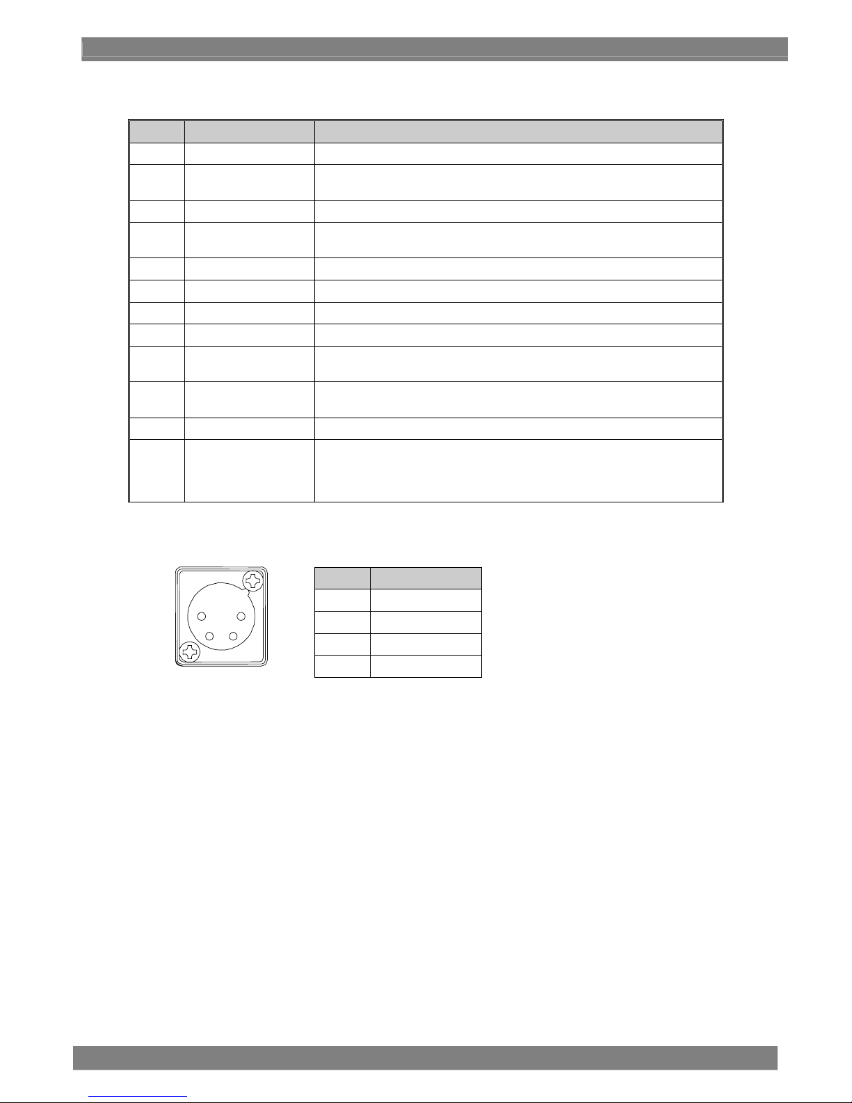
*3: REMOTE connector (Number (11))
Pin No. Description
1 GND
2 R1: User select
3 R2: User select
4 R3: User select
5 ENABLE_RMT
6 R4: User select
7 R5: User select
8 R6: User select
9 R7: User select
10 R8: User select
11 R9: User select
12 R10: User select
13 R11: User select
14 R12: User select
15 GND
This remote controller connector is used for external control (contact power supply system).
Pin 5, ENABLE_RMT, is used to determine whether external control (contact power supply system) is to be
executed.
If external control (contact power supply system) is being used, be sure to connect Pin 5, ENABLE_RMT, to
GND.
If Pin 5, ENABLE_RMT, is left open, settings made using external control (contact power supply system) will not
be executed.
For details, see “3.4.14 REMOTE ASSIGN”.
1
5
6
10
11
15
Page 21
Chapter 2 Names of Parts
9
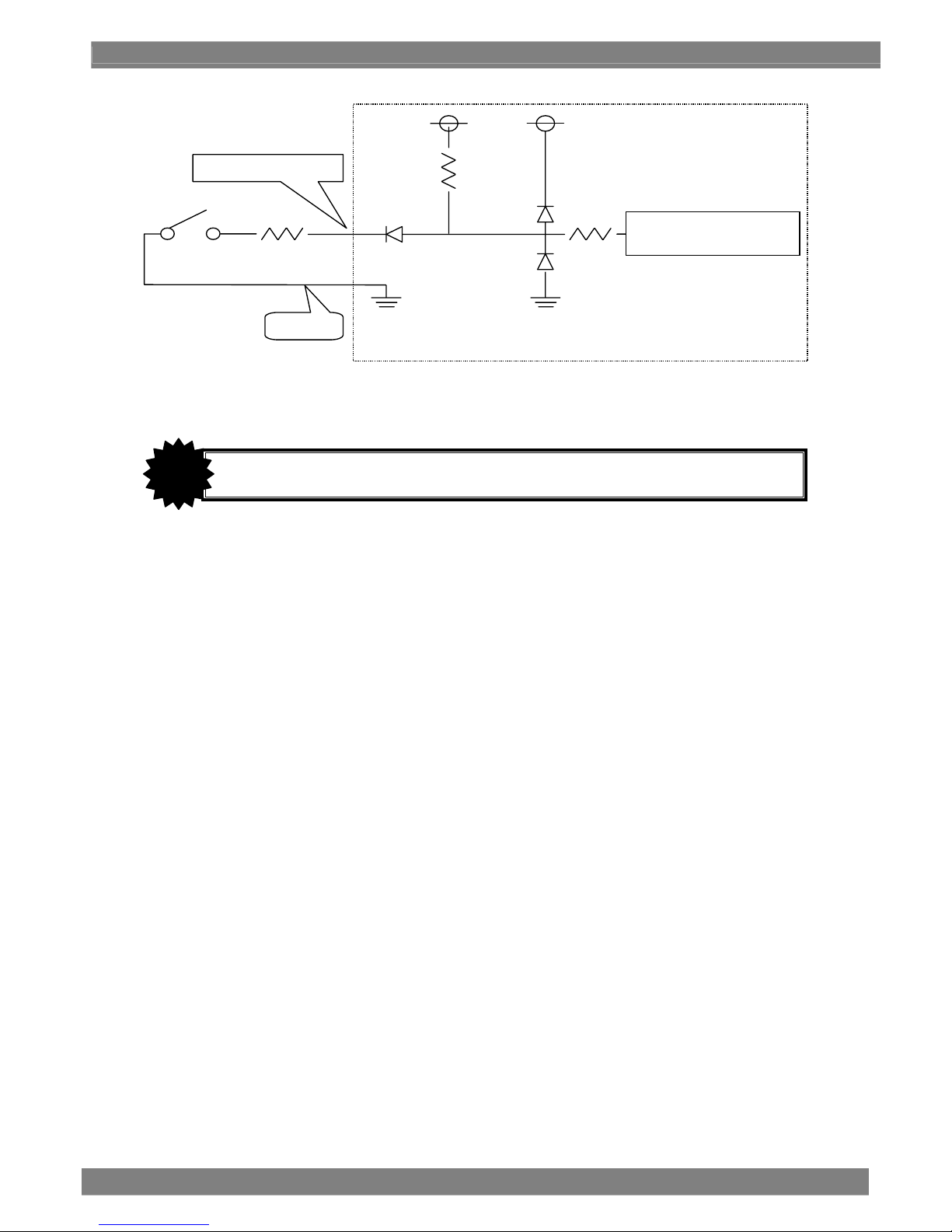
* Be sure that cable resistance is 50 Ω or less.
Remote controller switch
Control IC
Low-level threshold: 0.7 V
Remote connector receptacle
WM monitor
1 kΩCable resistance
Vf = 0.65 V
Remote control signal
Pin 1, 15
3.3 V
10 kΩ
3.3 V
CAUTION
Do not connect or disconnect the REMOTE connector while power is being supplied.
Page 22
10
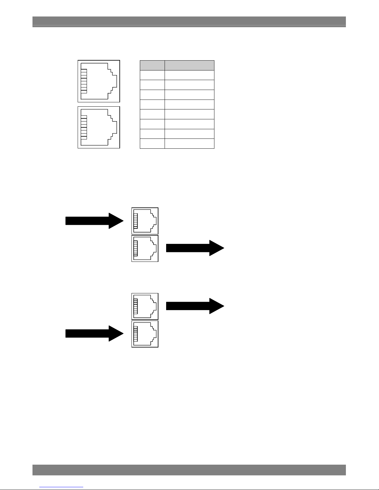
*4: RS485 connector (Number (12))
Pin No. Description
1 TXD+
2 TXD-
3 RXD+
4 GND
5 GND
6 RXD-
7 NC
8 NC
This remote controller connector is used for ID input. (Mounted only with the WM-3209-L)
One terminal is used for control signal input. When a terminal is used for control signal input, the other is used
as a through-output terminal.
<Case 1>
<Case 2>
Through-out
RS485 control signal
8
1
8
1
RS485 control signal
Through-out
Page 23

11
3
3
Method of Operation
3.1 Connections
This section describes connections of the WM-3209/WM-3209-L.
(1) Connecting the Power
When Using a Power Connector
Check that the POWER switch on the unit is OFF. Connect the XLR connector of the AC/DC
adapter to the power connector of the WM-3209/WM-3209-L ((1) on the rear panel.)
Confirm the shape of connectors before use.
(2) Connecting Input Signals
When Accepting a SDI Signal Input
When accepting a SDI signal input, connect a BNC coaxial cable to the SDI IN terminal ((2) and
(4) on the rear panel).
SDI IN is used for SDI signal input, while MONITOR OUT ((6) and (7) on the rear panel) is used
as output for easily verifying the input SDI.
As the 3G SDI input signals, input serial signals which comply with the SMPTE 425M standard.
As the HD-SDI input signals, input serial signals which comply with the SMPTE 292M standard.
For SD-SDI input signals, be sure to use a serial signal that conforms to SMPTE259M (270
Mbit/s)
When Accepting a DUAL LINK Signal Input
When inputting the dual link signals, connect the two sets of BNC coaxial cables to the SDI IN
connectors ((2) and (4) on the rear panel view).
When Dual Link1 has been selected as the input channel, input the Link A signals to the SDI A1
connector ((2) on the rear panel view) and the Link B signals to the SDI B1 connector ((4) on the
rear panel view).
Use serial signals complying with the SMPTE 372M standard for the dual link input signals.
The SDI IN connectors are used for the input of the SDI signals, and the MONITOR OUT A and
B ((6) and (7) on the rear panel view) connectors are used as outputs for the simply monitoring
of the SDI input signals.
When Accepting a COMPOSITE Signal Input
When accepting a composite signal, connect a BNC coaxial cable to COMPOSITE ((8) on the
rear panel). When using NTSC as the composite signal, be sure input a signal that conforms to
SMPTE170M. When using PAL, be sure to input a signal that conforms to ITU-R624-4.
When stereoscopic signals are input
When stereoscopic signals are input, connect two BNC coaxial cables to the SDI IN connectors
(connectors (2) and (4) on the rear panel). Connect the image to be viewed by the right eye to
the SDI A1 connector (connector (2) on the rear panel), and connect the image to be viewed by
the left eye to the SDI B1 connector (connector (4) on the rear panel)
Page 24
12
(3) Connecting a Remote Controller
When Using a Contact Power Supply System
Check that the POWER switch on the unit is OFF and connect the remote controller to REMOTE
((11) on the rear panel) of the WM-3209/WM-3209-L.
Confirm the shape of connectors before use.
When Using an External ID Display (WM-3209/WM-3209-L Only)
Check that the POWER switch on the unit is OFF and connect the remote controller to RS485
((12) on the rear panel) of the WM-3209/WM-3209-L.
Confirm the shape of connectors before use.
3.2 Method of Operation
A protective film is attached to the surface of the liquid crystal panel at time of shipment. Remove the
protective film before using the WM-3209/WM-3209-L
Check connections and then turn ON the power of the WM-3209/WM-3209-L using the POWER switch
on the front panel. The POWER LED will light and an image will be displayed.
If the POWER LED does not light, check connections again.
Use MONITOR OUT for easy verification of the SDI input signal.
If there is no input signal, the imaging area will appear black and the indicator
No Signal will be
displayed in red.
If no signals are input for LinkB of the dual link signals or there is a difference between the LinkA and
LinkB phases,
PhaseError is displayed in red on the screen.
When Dual Link has been selected as the input channel, a phase
difference equivalent to ±15 clock pulses between the LinkA signals and
LinkB signals is absorbed. If the LinkB signals are not input or the phase
difference cannot be fully absorbed,
PhaseError is displayed at
the bottom of the screen.
CAUTION
When Dual Link has been selected as the input channel, a phase difference
equivalent to ±15 clock pulses between the LinkA signals and LinkB signals is
absorbed. If the LinkB signals are not input or the phase difference cannot be
fully absorbed,
PhaseError is displayed at the bottom of the screen.
CAUTION
Page 25

Chapter 3 Method of Operation
13
3.3 Switch Specifications
This section describes the switch specifications of the WM-3209/WM-3209-L.
3.3.1 INPUT Switch
Switches the input channel.
Switches the input only to those input channels for which INPUT CHANNEL has been set to ENABLE
on the MENU.
Ex. When ENABLE is set for all input channels
SDI_A1 => SDI_B1 => COMPOSITE => DUAL LINK => SDI_A1 ・・・
Ex. When ENABLE is set for SDI_A and COMPOSITE
SDI_A1 => COMPOSITE => SDI_A1 ・・・
For details see “3.4.2 INPUT CHANNEL”.
SDI_A1/A2, SDIA_B1/B2 and Dual Link1/2 for INPUT CHANNEL on the menu screen can be assigned
to U1 to U4.
For details, see “3.4.13 SWITCH ASSIGN”.
Page 26
14
3.3.2 COLOR Switch
This is the color information setting screen (COLOR adjustment mode).
Pressing the COLOR switch once displays the color information setting screen on the monitor screen.
Pressing the COLOR switch again makes the color information setting screen go away.
The following color information can be set: Information, Marker, Cursor, Scale, Waveform, Vector,
Audio Vector, and Status.
Pressing the COLOR switch a yet again displays the color information setting screen at the previous
cursor position.
Info Color White 2
Mark Color White 3
Cursor White 2
Scale White 2
Wave White 2
Vecto
r
White 2
A
ud_Meter White 2
A
ud_Vec White 2
Status White 2
Page 27

Chapter 3 Method of Operation
15
3.3.3 FREEZE Switch
Pressing the FREEZE switch once freezes the current image on the screen.
Pressing the FREEZE switch again updates the frozen image.
In the FREEZE status, FREEZE is displayed in blue on the screen.
3.3.4 U1 through U4 Switches
Activates the function assigned by switch assignment. (For details, see “3.4.13 SWITCH ASSIGN”.)
3.3.5 Preset Switch
Pressing the PRESET switch displays the Preset screen. Pressing the PRESET switch again makes
the Preset screen go away.
Data corresponding to Preset1 through Preset8 can be loaded or saved on the Preset screen.
Loading Preset1 through 8
Pressing the PRESET switch while in Preset mode displays LOAD_PRESET1 through 4 in the function
indicator. Pressing any of the F1 through F4 switches will load the corresponding Preset data (screen
and settings).
Saving Preset1 through 8
Pressing the PRESET switch in a mode other than Preset mode displays SAVE_PRESET1 through 4 in
the function indicator. Pressing any of the F1 through F4 switches saves the current screen and
settings as the corresponding Preset data.
For details, see “4.1 Preset Mode”.
3.3.6 MENU Switch
Pressing once displays the MENU screen. Pressing again makes the MENU screen go away.
The key lock status is established by holding down the menu switch, and no further operations can be
performed except for the releasing of the key lock which can be achieved by holding down the mode
switch and menu switch.
When the key lock status has been set, the "AUTO SAVE & KEY LOCK!!!" message is displayed. At
this time, the settings are saved in BOOT of the memory by the automatic save function provided by the
monitor. The automatic save function can be set to ON or OFF.
When the function is set to OFF, the "KEY LOCK!!!" message is displayed when the key lock status has
been set. At this time, the settings are not saved in BOOT of the memory. For details on the automatic
save function, refer to "3.4.16 HARDWARE SETTING."
Pressing a switch on the front panel during key lock displays “KEY_LOCK!!!” on the screen.
Holding down the MENU switch during key lock displays “KEY_UNLOCK!!!” on the screen.
Releases key lock. The LED on the front panel lights orange during key lock.
3.3.7 ESC Switch
Moves up one level if the MENU screen is being displayed. Functions are subject to the specifications
of each mode when the MENU screen is not being displayed.
Page 28
16
If ESC is pressed while saving or clearing picture memory, the operation in question is cancelled.
For details, see “3.4.4 COMPARE”.
3.3.8 F1 through F5 Switches
Pressing any of F1 through F5 once displays the function indicator. Pressing the same switch again in
this state executes the associated function.
During initial setup, the function indicator will disappear after 10 seconds unless a switch is pressed.
The function indicator display time can be set. For details, see “3.4.7 DISPLAY”.
Functions are assigned to F1 through F5 for each mode. For details, see “Chapter 4: Description of
Each Mode in Chapter 4.”
3.3.9 Mode Switches
Displays each mode screen. Mode screens are listed in the table below.
Indication on the unit Mode Screen
PRESET Preset Mode
PICTURE1 Picture Mode 1
PICTURE2 Picture Mode 2
WAVEFORM Waveform Mode
VECTOR Vector Mode
STATUS Status Mode
AUDIO Audio Mode
PHASE Phase Comparison Mode
ANC Multiplexed packet check mode
MULTI Multimode 1 - 5
OPTION
Option Mode 1 - 2
COMPARE1
Compare Mode 1 Overlap
Compare Mode 1 Vertical
COMPARE2
Compare Mode 2 Horizontal
Compare Mode 2 Vertical
COMPARE3
Compare Mode 3 Horizontal
Compare Mode 3 Vertical
COMPARE4
Compare Mode 4 Horizontal
Compare Mode 4 Vertical
COMPARE5
Compare Mode 5 Horizontal
Compare Mode 5 Vertical
Page 29
Chapter 3 Method of Operation
17
3.4 Description of the MENU Screens
This section describes the switch specifications of the WM-3209/WM-3209-L.
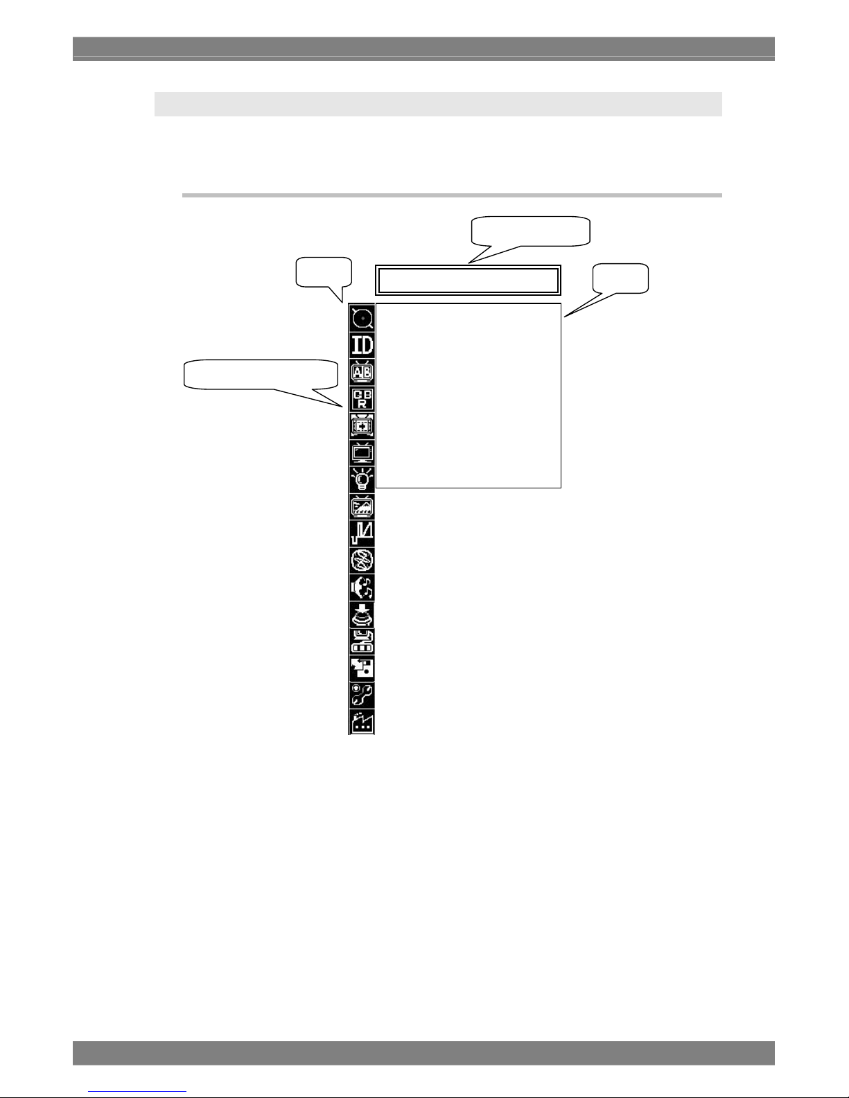
3.4.1 MENU Screen Details (Basic Operations)
• Pressing the MENU switch enters the MENU screen. Pressing the MENU switch again makes
the MENU screen go away. Furthermore, the monitor's specifications are such that when the
format of the input signals has been changed while the menu screen is displayed, the mode
screen may be restored from the menu screen but images in the new format will still be drawn
stably.
• The MENU screen is hierarchical. When you enter the MENU screen, items up to Level 2 are
displayed. Align the cursor and turn the Adjustment Dial to move to the next level.
• If the MENU screen is displayed again, the menu level and item last adjusted are displayed
regardless of the input channel.
• Pressing the ESC switch moves up one level. Nothing changes if you press the ESC switch on
Level 1.
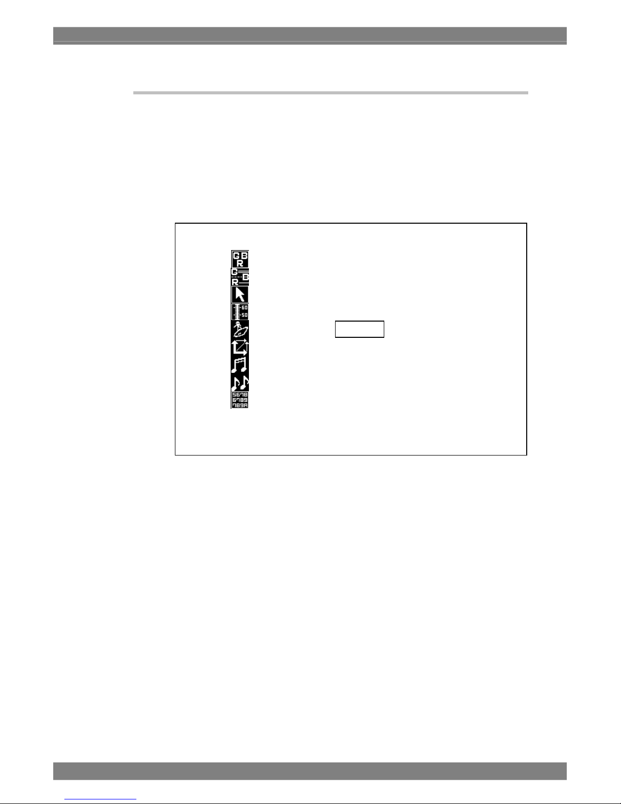
* Selected icons on Menu Level 1 are highlighted.
Level 2
Level 1
Menu Item Name
Selected Menu Item (*)
MARKER SETTING
Display O
N
Select Marker
Box H Posi 1023pi
x
Box V Posi 760pi
x
Box Width 1024pi
x
Box Height 760pi
x
User H 50
%
User V 50
%
Thickness ×1
Page 30
18
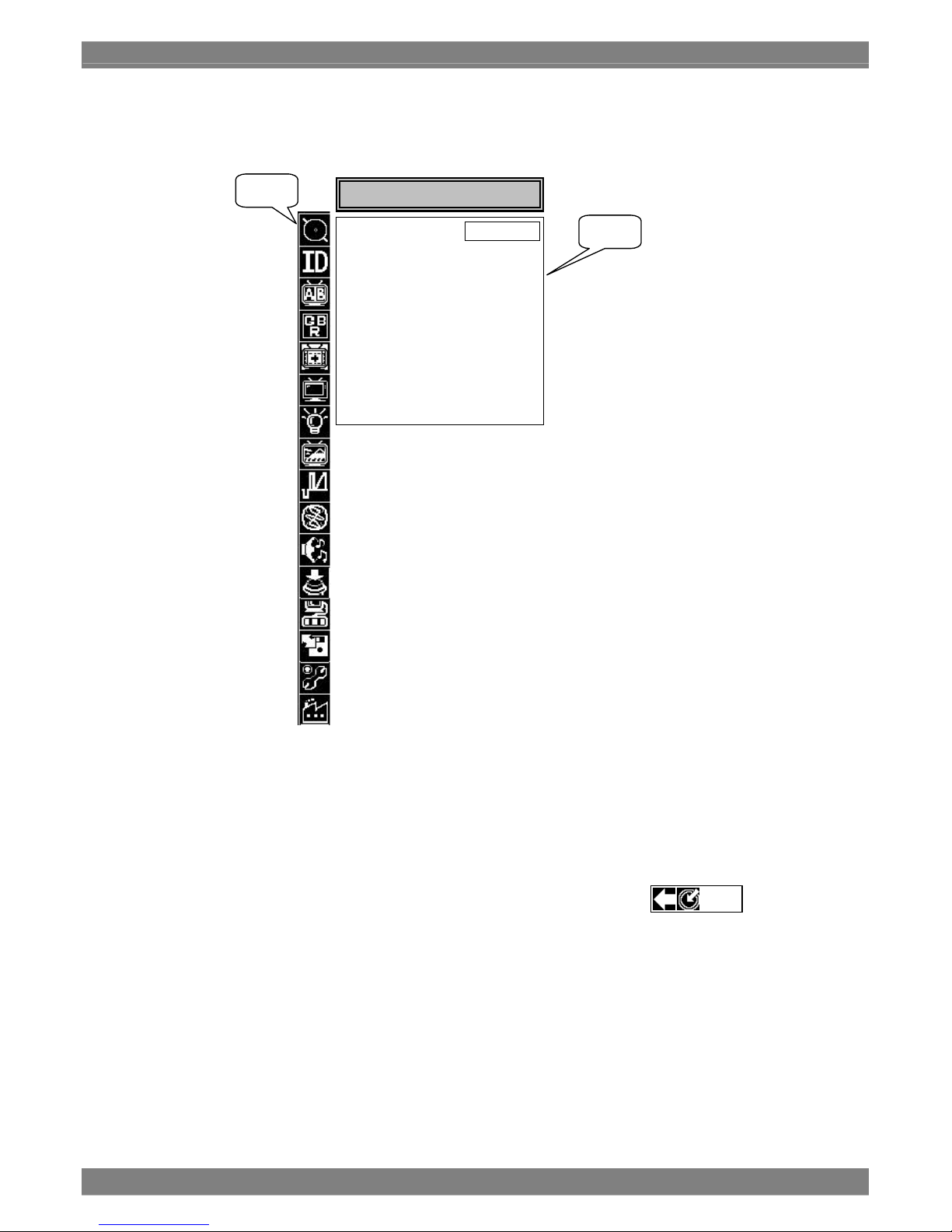
Level 2
• Turning the Adjustment Dial on Level 1 enters Level 2 and the cursor is displayed within Level
2.
The text of menu item names are highlighted.
• Menu items up to Level 3 are displayed for those items that go up to Level 3.
• Turning the Adjustment Dial while on Level 2 allows that part of an item to be adjusted. Text is
highlighted during adjustment.
• To move to Level 1, press the ESC switch or align the cursor with and turn
the Adjustment Dial.
When exiting Level 2, the text of menu item names is returned to normal display.
Level 1
Level 2
MARKER SETTING
Display ON
Select Marker
Box H Posi 1023pi
x
Box V Posi 760pi
x
Box Width 1024pi
x
Box Height 760pi
x
User H 50
%
User V 50
%
Thickness ×1
ESC
Page 31

Chapter 3 Method of Operation
19
Level 3
• If is displayed as the arrow between levels 2 and 3 for an item that has level 3, press the
adjustment dial to enter level 3, and the cursor will be displayed within level 3.
If the adjustment dial is pressed while the is displayed as the arrow between levels 2 and 3, the
items displayed on level 3 are selected in turn (but the cursor does not move to level 3).
• If the adjustment dial is pressed while the cursor is within level 3, the item in the area
concerned can be adjusted or set.
• If, while the cursor is within level 3, the ESC switch is pressed or the cursor is aligned with
and the adjustment dial is pressed, the cursor moves back to level 2.
Level 1
Level 2
Level 3
MARKER SETTING
Display ON
Select Marker
Box H Posi 1023pi
x
Box V Posi 760pi
x
Box Width 1024pi
x
Box Height 760pi
x
User H 50
%
User V 50
%
Thickness ×1
Frame
Center
95%
93%
88%
80%
4:3
13:9
14:9
2.35:1
1.85:1
1.66:1
Grating
Box
User
ESC
Page 32

20
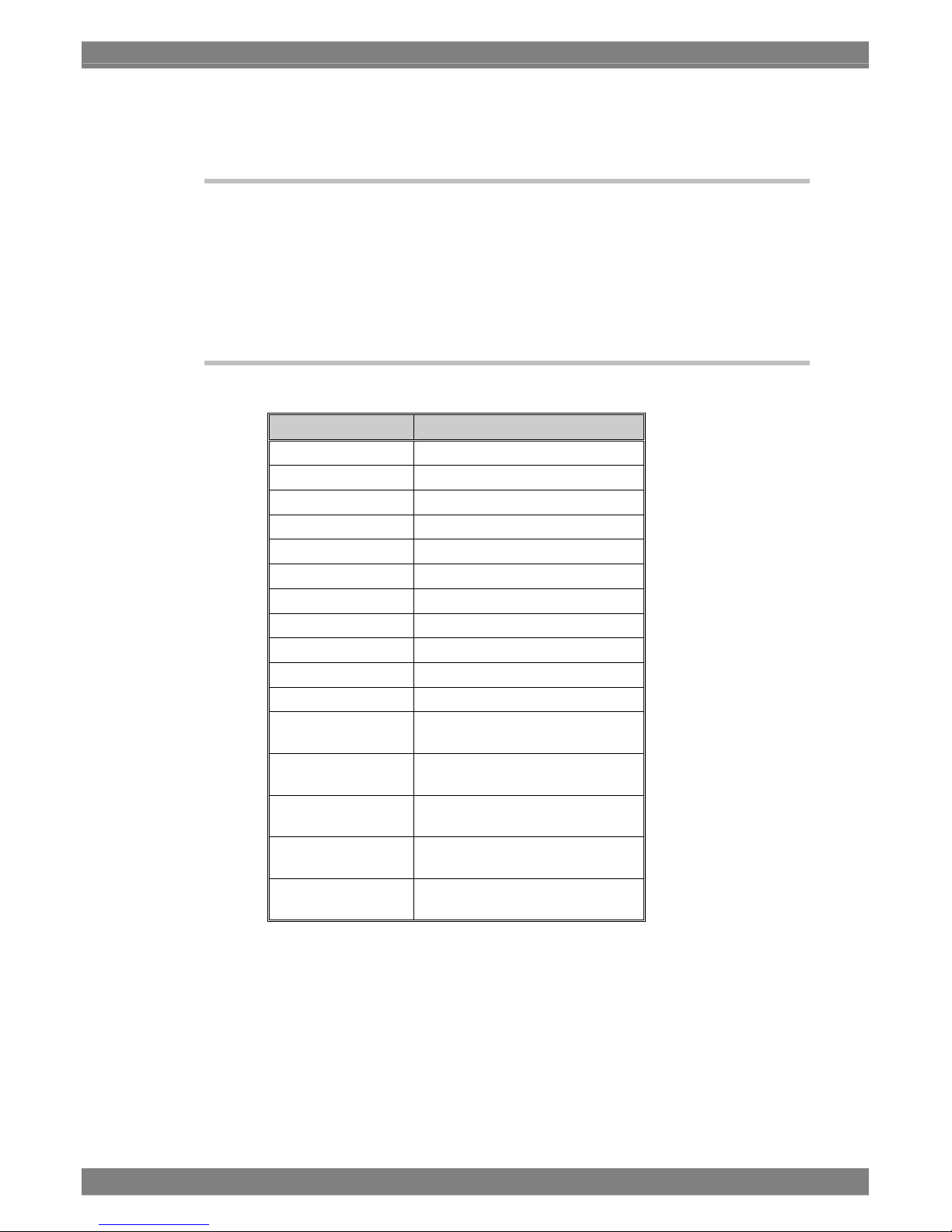
Overview of Names and Functions on Level 1
*1: External ID mode or Unit_No can be set only with the WM-3209-L.
*2: With the WM-3209 or WM-3209-L, there is no need to set the function items related to the
display of the icon which indicates the remaining battery charge.
Front Switch Operations
Adjustment Dial Operations
Turning counterclockwise Lowers the value being adjusted or moves the cursor left or up
Turning clockwise Increases the value being adjusted or moves the cursor right or
down
Pressing the switch Confirms the value to be changed to or toggles ON/OFF, etc.
Holding down the switch Restores the setting value to default
Hierarchical Name: Description
3.4.2 INPUT CHANNEL
Sets the input channel
3.4.3 ID SETTING
Sets the IDs of the input channels (SDI_A1 to SDI_B2,
Composite, dual link). (*1)
3.4.4 COMPARE Makes settings related to dual-screen display
3.4.5 PICTURE QUALITY Adjusts the image color, etc.
3.4.6 MAKER Sets markers
3.4.7 DISPLAY Selects the information to be displayed on-screen (*2)
3.4.8 TALLY Selects a tally
3.4.9 PICTURE Makes picture settings
3.4.10 WAVE Makes wave settings
3.4.11 VECTOR Makes vector settings
3.4.12 AUDIO Makes audio settings
3.4.13 SWITCH ASSIGN Selects the functions assigned to U1 through U4.
3.4.14 REMOTE ASSIGN Selects the functions assigned to remote control 1 through 5.
3.4.15 LOAD & SAVE Saving and loading the current state.
3.4.16 HARDWARE SETTING Establishing the hardware-related settings (*2)
3.4.17 RESET CALL
Initializes the setting items for each input channel and loads
factory settings
Turns the MENU screen ON/OFF
MENU
Moves up one level
ESC
Page 33

Chapter 3 Method of Operation
21
3.4.2 INPUT CHANNEL
These setting items are used to set the input channels (SDI_A1 to SDI_B1, Composite, dual link) as
described in the table below.
Setting Item Description Default
SDI_A
Enable: Allows input SDI A1 to be selected as
the input channel.
Disable: Disables the selection of input SDI A1.
(*1)
Enable
SDI_B
Enable: Allows input SDI B1 to be selected as
the input channel.
Disable: Disables the selection of input SDI B1.
(*1)
Enable
COMPOSITE
Enable: Allows input Composite to be selected
as the input channel.
Disable: Disables the selection of input
Composite. (*1)
Enable
NTSC_SETUP
7.5IRE: Support for signal input with 7.5IRE
setup.
OFF: Support for signal input with no setup.
OFF
DUAL LINK (*2)
Enable: Allows input DUAL LINK to be
selected as the input channel.
Disable: Disables the selection of input DUAL
LINK. (*1)
10/12bit (*3)
10 bits: Sets the sample data to 10 bits.
12 bits: Sets the sample data to 12 bits.
10bit
Sampling Sel
(*3)
4:2:2: Ensures that the sampling structure
supports the 4:2:2 color resolution.
4:4:4: Ensures that the sampling structure
supports the 4:4:4 color resolution.
4:2:2
Color Space
(*3)
YPbPr: Sets the color space of the input
signals to YPbPr.
GBR: Sets the color space of the input
signals to GBR.
YPbPr
Auto CS Cnv
ON: When a payload is superimposed onto
the input signals, 10 bits or 12 bits,
4:2:2 or 4:4:4 and YPbPr or GBR are
set in accordance with the value of the
payload. When a payload is not
superimposed, the 10/12bit,
SamplingSel and Color Space settings
take effect.
OFF: The 10/12bit, SamplingSel and Color
Space settings take effect regardless
of whether the payload is
superimposed.
ON
*1: The current input channel cannot be set to DISABLE.
*2: For details on the dual link signals, refer to “5.9 Concerning the Dual Link Input Settings.”
*3: When ON is selected as the AutoCSCnv setting and a payload (SMPTE 352M standard) is
superimposed, these settings are ignored.
Page 34

22
• Hierarchical MENU Screen Image
• Setting Method
1. Align the cursor with INPUT_CHANNEL and press the Adjustment Dial.
2. When the cursor is aligned with the item whose setting is to be changed and the
adjustment dial is pressed, the setting is changed.
3.4.3 ID SETTING
These setting items are used to set the IDs of the input channels (SDI_A1 to SDI_B1, Composite, dual
link) as described in the table below.
Setting Item Description Default
DISPLAY
ON: Displays the channel IDs.
OFF: Hides the display of the channel IDs.
ON
ID Select (*1)
Internal: Displays the ID set with Internal ID Edit.
External: Inputs an ID from an external source
using RS485 communications. (*2)
Internal
On Picture
ENABLE: Displays the IDs in all the modes.
DISABLE: Hides the display of the IDs in the
following modes.
PICTURE2, MULTI2, MULTI3,
COMPARE1_H, COMPARE2_H,
COMPARE3_H, COMPARE4_H,
COMPARE5_H
DISABLE
Internal ID Edit (*3)
Sets the ID to be displayed during Internal mode. SDI IN A1: SDI_A1
SDI IN B1: SDI_B1
COMPOSITE IN:
COMPOSITE
DUAL LINK1 IN: DUAL
LINK1
External ID (*1)
Represents the Unit NO. when inputting an ID
using RS485 communications.
1 (*4)
*1: Operation and selection of this setting item are possible only for the WM-3209-L model. However, no
changes can be made when the Flash Protect function is ON. (For details on the Flash Protect
function, refer to "5.17 Concerning the Flash Protect function.")
*2: Operation and selection of this setting are possible only for the WM-3209-L model.
*3: Up to 10 characters of text can be used to represent each input channel.
Characters that can be used in Internal mode include: upper and lowercase alphabetic characters,
numeric characters, and basic symbols.
*4: The settings are automatically saved when they are selected.
SDI_A ENABLE
DI_B DISABLE
COMPOSITE ENABLE
NTSC_SETUP 7.5IRE
DUAL LINK ENABLE
10/12bit 10bit
Sampling Sel 4:4:4
Color Space YpbPr
Auto CS Cnv ON
INPUT_CHANNEL
4:2:2
4:4:4
Page 35

Chapter 3 Method of Operation
23
• Hierarchical MENU Screen Image
! ” # $ % & ’ ( ) * + , - . /
0 1 2 3 4 5 6 7 8 9 : ; < = > ?
@ A B C D E F G H I J K L M N O
P Q R S T U V W X Y Z [ \ ] ^ _
` a b c d e f g h i j k l m n o
p q r s t u v w x y z { | }  ̄
• Setting Method
1. Align the cursor with ID SETTING and press the Adjustment Dial.
2. Align the cursor with the item whose setting is to be changed and press the
Adjustment Dial.
* When ID Select is selected, INTERNAL and EXTERNAL are alternately displayed.
(WM-3209-L only)
* When Internal ID Edit is selected, the name of the channel currently being
displayed can be changed.
* When External ID is selected, unit numbers 1 to 254 can be selected. WM-3209-L
only)
3. To set a unit number, turn the adjustment dial to select the number, and press the
adjustment dial to enter the setting.
* After adjusting the value using the Adjustment Dial, the value cannot be set
without pressing the Adjustment Dial.
* Holding down the Adjustment Dial restores the default value.
* The unit numbers are automatically saved when they are selected.
• Changing the ID Name in INTERNAL Mode (When Internal ID Edit is Selected)
1. Align the cursor with the text to be changed and turn the Adjustment Dial to move the
cursor to the character to be set.
2. Press the Adjustment Dial
SDI A1
Display ON
ID Select INTERNAL
On Picture DISABLE
Internal ID Edit
Unit No 1
ID SETTING
Display ON
ID Select INTERNAL
On Picture DISABLE
Internal ID Edit
External ID
ID SETTING
Unit No. 1
Page 36

24
* Characters are confirmed one at a time.
* The currently selected character is highlighted.
Each time the character changes, the character in the ASCII table will also move
to match that character.
* Up to 10 characters consisting of upper or lowercase alphabetic characters,
numeric characters, and/or basic symbols can be displayed.
* Kanji can be displayed for IDs only in EXTERNAL mode.
• Supplement
Each channel has an associated ID.
3.4.4 COMPARE
Select another channel (Another_CH) for comparisons in Compare mode or Phase Compare mode.
Setting items are as follows.
Setting Item Description Default
Compare Pic (*1) Another_CH:
Compares with the input signal.
3G HD2X:
3G-SDI Level B signal is split and displayed as
data stream1 and 2.
Memory1 through 4:
Compares with saved memory data.
CB-100%/CB-75%:
Compares with 100% color bars and 75% color
bars.
Another_CH
Another_CH (*1) SDI_A: Compares with the SDI_A input
signal.
SDI_B: Compares with the SDI_B input
signal.
Composite: Compares with the composite input
signal.
When SDI_A1
is selected:
SDI_B
When SDI_B1
is selected:
SDI_A
When
Composite is
selected: SDI_A
Save Memory(*2, *3)
Saves the input channel image to flash memory. None
Clear Memory(*2, *3) Memory1 through 4:
Clears selected memory data.
None
Own H Mirror
Enable/disable the inverse function of Owner CH
signal horizontally.
OFF
Own V Mirror
Enable/disable the inverse function of Owner CH
signal vertically.
OFF
Ano H Mirror
Enable/disable the inverse function of Another
CH signal horizontally.
OFF
Ano V Mirror
Enable/disable the inverse function of Another
CH signal vertically.
OFF
Compare 3D
Enable/disable the synchronization of Compared
signal frame.
ON
Disp1 Size
Customize the Disp 1’s display size of the
display difference simulation of Display 1
compare mode .
100 inch
Disp1 Aspect
4:3 : Set aspect ratio of Display 1 to 4:3.
16:9 : Set aspect ratio of Display 1 to 16:9.
2.35:1:Set aspect ratio of Display 1 to 2.35:1.
4:3
Page 37

Chapter 3 Method of Operation
25
Disp2 Size
Customize the Disp 2’s display size of the
display difference simulation of Display 1
compare mode.
100 inch
Disp2 Aspect
4:3 : Set aspect ratio of Display 2 to 4:3.
16:9 : Set aspect ratio of Display 2 to 16:9.
2.35:1:Set aspect ratio of Display 2 to 2.35:1.
4:3
Unit
cm:
Set unit of display difference simulation to cm .
inch:
Set unit of display difference simulation to inch.
cm
*1: The monitor's specifications are such that when the selected signal has a format which differs from
the format of the signal input before this item was set, the menu screen may be exited but images in
the new format will still be drawn stably.
*2: The settings of these items cannot be changed when the Flash Protect function is ON. (For details
on the Flash Protect function, refer to "5.17 Concerning the Flash Protect function.")
*3: Error count and the elapsed time stop while data is being saved in the memory or the memory is
being cleared, but since priority is given to operations involving the memory, the drawing of the
images based on the data concerned is stopped temporarily. The actual error count and elapsed
time recording still continues even while the memory is being accessed. After the data has been
saved in the memory or the memory has been cleared, updating on a real-time basis is selected
again.
Page 38

26
• Hierarchical MENU Screen Image
• Setting Method
1. Align the cursor with COMPARE and press the Adjustment Dial.
2. Align the cursor with the item whose setting is to be changed and press the
Adjustment Dial.
COMPARE
Compare Pic AnotherCH
Another CH SDI A
Save Memory
Clear Memory
Own H Mirror ON
Own V Mirror OFF
Ano H Mirror OFF
Ano V Mirror OFF
Compare 3D ON
Disp1 Size 256inch
Disp1 Aspect 16:9
Disp2 Size 100inch
Disp2 Aspect 4:3
Unit cm
SDI A
SDI B
Composite
AnotherCH
3G HD2X
Memory 1
Memory 2
Memory 3
Memory 4
CB-100%
CB-75%
Compare Pic AnotherCH
Another CH SDI A
Save Memory
Clear Memory
Own H Mirror ON
Own V Mirror OFF
Ano H Mirror OFF
Ano V Mirror OFF
Compare 3D ON
Disp1 Size 256inch
Disp1 Aspect 16:9
Disp2 Size 100inch
Disp2 Aspect 4:3
Unit cm
COMPARE
Page 39

Chapter 3 Method of Operation
27
When the input channel is set to Dual Link, the channel to be compared to
(Another CH) setting is always SDI B.
CAUTION
In the Compare mode, the display of the images in the channel to be
compared to (Another CH) is delayed by one frame.
A
s an exception to this, when the input channel is set to Dual Link, the images
of the channel to be compared to (Another CH) are displayed with no delay.
However, the formats and phases of the two inputs (SDI A and SDI B) must
match.
Own H Mirror, Own V Mirror, Ano H Mirror and Ano V Mirror function is
expecting conditions listed above, In other conditions, it will be not warrant
that unit behave correctly.
CAUTION
Dual link inputs are not supported in the phase comparison mode or
COMPARE1 to 5 modes. The display of the images, waveforms and vectors in
these modes are processed by Single Link.
CAUTION
When Dual Link1 has been selected for the input channel, the input channel
whose data is saved b
y
SAVE MEMORY is set to SDI A1.
CAUTION
Page 40

28
• The Save Memory Screen Image and Canceling Processing
Approximately one minute is required to save memory data.
To cancel saving data, press the ESC switch. The save operation is cancelled and focus
returns to Level 2.
Highlighting flashes repeatedly during SAVE.
COMPARE
Compare Pic AnotherCH
Another CH SDI A
Save Memory
Clear Memory
Own H Mirror ON
Own V Mirror OFF
Ano H Mirror OFF
Ano V Mirror OFF
Compare 3D ON
Disp1 Size 256inch
Disp1 Aspect 16:9
Disp2 Size 100inch
Disp2 Aspect 4:3
Unit cm
Memory1
Memory2
Memory3
Memory4
WAIT!!!
Push[ESC] to cancel the writing procedure.
Page 41

Chapter 3 Method of Operation
29
z
• The Clear Memory Screen Image and Canceling Processing
Approximately one minute is required to clear memory data. Data cleared from memory is
displayed as a black fill pattern. To cancel clearing data, press the ESC switch. The clear
operation is cancelled and focus returns to Level 2.
Highlighting flashes repeatedly during CLEAR.
COMPARE
Compare Pic AnotherCH
Another CH SDI A
Save Memory
Clear Memory
Own H Mirror ON
Own V Mirror OFF
Ano H Mirror OFF
Ano V Mirror OFF
Compare 3D ON
Disp1 Size 256inch
Disp1 Aspect 16:9
Disp2 Size 100inch
Disp2 Aspect 4:3
Unit cm
Memory1
Memory2
Memory3
Memory4
WAIT!!!
Push[ESC] to cancel the writing procedure.
Do not turn power OFF during SAVE or CLEAR operations. Except for the
ESC switch, switches on the front panel do not respond during SAVE or
CLEAR operations.
Furthermore, a video image cannot be displayed normally for memory data fo
r
which SAVE or CLEAR operations were cancelled.
CAUTION
Page 42

30
3.4.5 PICTURE QUALITY
Adjust the liquid crystal display. Setting items are as follows.
Setting Item Description Default
ColorTemperture
5500k: Sets a color temperature of 5500k
6500k: Sets a color temperature of 6500k
9300k: Sets a color temperature of 9300k
6500k
G,B,R-Bright (*1, *2)
-50.0 to +50.0% 0.0%
G,B,R-Contrast (*1, *2)
0.0 to 200.0% 100.0%
G,B,R-Gamma (*1)
1.00 to 4.00 2.20
*1: G,B,R-Bright, G,B,R-Contrast, and G,B,R-Gamma possess independent setting values for each color
temperature.
*2: Bright and Contrast setting items are also available in "4.2 Picture Mode 1," but the settings of these
items are common to all the channels.
• Hierarchical MENU Screen Image
• Setting Method
1. Align the cursor with PICTURE_QUALITY and press the Adjustment Dial.
2. Align the cursor with the item whose setting is to be changed and press the
Adjustment Dial.
3. To set numeric values, turn the Adjustment Dial to adjust the setting value, and press
the Adjustment Dial to confirm it.
* After adjusting the value using the Adjustment Dial, the value cannot be set
without pressing the Adjustment Dial.
* Holding down the Adjustment Dial restores the default value.
PICTURE QUALITY
Color Temperature 6500K
G-Bright 0.0%
B-Bright 0.0%
R-Bright 0.0%
G-Contrast 100.0%
B-Contrast 100.0%
R-Contrast 0.0%
G-Gamma 2.20
B-Gamma 2.20
R-Gamma 2.20
Page 43

Chapter 3 Method of Operation
31
3.4.6 MARKER
Set marker displays. Setting items are as follows.
Setting Item Description Default
Display (*1)
ON: Displays the selected marker
OFF: Hides the selected marker
OFF
SelectMaker
Frame: Frame
Center: Center
95%: 95% frame for the video image
93%: 93% frame for the video image
88%: 88% frame for the video image
80%: 80% frame for the video image
4:3: Border around the 4:3 area of the video
image
13:9: Border around the 13:9 area of the
video image
14:9: Border around the 14:9 area of the
video image
2.35:1: Border around the 2.35:1 area of the
video image
1.85:1: Border around the 1.85:1 area of the
video image
1.66:1: Border around the 1.66:1 area of the
video image
Grating: Grid-shaped markers
Box: Rectangular markers (user adjustable)
User: Vertical/horizontal linear markers (user
adjustable)
Frame
Center
Box_H_Pos (*2)
0 to 1023 166
Box_V_Pos (*2)
0 to 767 125
Box_Width (*2)
1 to 1024 692
Box_Heght (*2)
1 to 768 518
User_H (*3)
0 to 100% 50%
User_V (*3)
0 to 100% 50%
Thickness (*4)
×1/×2/×3/×4 ×1
*1: The ON/OFF setting for Marker is reflected in the PICTURE1 mode, PICTURE2 mode, MULTI
modes 1 to 5, OPTION mode, and COMPARE1 to 5 modes.
For further details on Marker, see “4.2 Picture Mode 1,” “4.3 Picture Mode 2,” “4.10 Multi Mode,”
“4.12 Compare Mode 1,” “4.13 Compare Mode 2,” “4.14 Compare Mode 3,” “4.15 Compare Mode 4”
and “4.16 Compare Mode 5.”
*2: Make settings for the BOX marker. (Set the horizontal and vertical coordinates for the start point, the
horizontal width, and the vertical height.)
*3: Set user markers. (Set the horizontal width and vertical height of the start point.)
*4: Determine the line width of the marker.
(The line width is fixed at one for Frame markers and Grating markers.)
Page 44

32
• Hierarchical MENU Screen Image
• Setting Method
1. Align the cursor with MAKER and press the Adjustment Dial.
2. Align the cursor with the item whose setting is to be changed and press the
Adjustment Dial.
* The only Level 3 information is a list of markers displayed under the Select Marker
item.
* The currently selected marker is highlighted.
3. To set numeric values, turn the Adjustment Dial to adjust the setting value, and press
the Adjustment Dial to confirm it.
* After adjusting the value using the Adjustment Dial, the value cannot be set
without pressing the Adjustment Dial.
* Holding down the Adjustment Dial restores the default value.
MAKER
Frame
Center
95%
93%
88%
80%
4:3
13:9
14:9
2.35:1
1.85:1
1.66:1
Grating
Box
User
Display O
N
Select Marker
Box H Posi 1023pi
x
Box V Posi 760pi
x
Box Width 1024pi
x
Box Height 760pi
x
User H 50
%
User V 50
%
Thickness ×1
Page 45

Chapter 3 Method of Operation
33
• Displaying/Hiding Markers for Each Aspect and Mode
HD Format
Aspect
Marker to be Checked
Normal
4:3
SCOPE
×2
×4
Compare
Multi 1.4
Mini
(Waves, etc.)
Center Marker
*
Frame Marker
*
*
95%, 93%, 88%, 80%
(Note)
*
4:3 marker
*
*
13:9, 14:9 marker
*
*
2.35:1 marker
* *
*
1.85:1, 1.66:1 marker
* *
*
User marker
*
SD Format
Aspect
Marker to be Checked
Normal
4:3
16:9
×2
×4
Compare
Multi 1.4
Mini
(Waves, etc.)
Center Marker
*
Frame Marker
*
* *
*
95%, 93%, 88%, 80%
*
4:3 marker * *
* * * * *
13:9, 14:9 marker
*
* *
*
2.35:1 marker
*
* *
*
1.85:1, 1.66:1 marker
*
* *
*
User marker (Note)
*
: Indicates the marker is displayed (size varies depending on the input video image)
*: Indicates the marker is hidden.
Note: Indicates the marker is displayed as a percentage of 1024×768.
Page 46

34
3.4.7 DISPLAY
Turn the display of information ON/OFF. Setting items are as follows.
Setting Item Description Default
Information (*1)
ON: Displays the information
OFF: Hides the information
ON
-ID Text
ON: Displays the Channel ID
OFF: Hides the Channel ID
ON
-Format(*2)
ON: Displays format information for three
seconds
OFF: Hides format information
ON
-Time Code
ON: Displays the time code
OFF: Hides the time code
ON
-Err Status
ON: Displays error information
OFF: Hides error information
ON
-Audio
ON: Displays the Audio Level Meter
OFF: Hides the Audio Level Meter
ON
-Battery (*4)
ON: Displays the Battery Level Icon
OFF: Hides the Battery Level Icon
OFF
Indicator
Infi: Always displays indicators.
5 sec: Displays indicators for only five
seconds.
10 sec: Displays indicators for only 10 seconds.
10 sec
Menu Shadow
ON: Masks the menu background with black
OFF: Does not mask the menu background
OFF
TC Select (*3)
VITC: Displays the VITC.
LTC: Displays the LTC.
OTHERS: Displays the time code for the user.
VITC
Gamut Alarm (*5)
ON: Lights the Gamut Error Indicator
OFF: Does not light the Gamut Error Indicator
ON
-Th Hi (*6)
+90 to +108%:
Sets the Gamut error upper limit threshold
+103%
-Th Low (*6)
-7 to +5%:
Sets the Gamut error lower limit threshold
-3.5%
Reverse Scan
ON: Displays with top-bottom reversed
OFF: Displays without reversing top-bottom
OFF
*1: The Information item is used to turn ID Text, Format, Time Code, Err Status and Audio ON/OFF
simultaneously.
If Information is set to OFF, ID Text, Format, Time Code, Err Status and Audio are all automatically
turned OFF, and cannot be selected or set.
*2: Format information includes reference information.
*3: Depending on the TC Select setting, the time code status display on the monitor screen changes to
VITC, LTC or **TC.
*4: This setting is not used by the WM-3209 or WM-3209-L model. Its specification is such that it is
always OFF, and it cannot be changed.
*5 Regardless of whether the error indicator is lit/unlit, the Gamut error counter and time of occurrence
are updated.
*6 A Gamut error is determined if the signal is outside the range of the upper and lower limits for the
Gamut error.
Page 47

Chapter 3 Method of Operation
35
• Hierarchical MENU Screen Image
• Setting Method
1. Align the cursor with DISPLAY and press the Adjustment Dial.
2. Align the cursor with the item whose setting is to be changed and press the
Adjustment Dial.
DISPLAY
Information ON
- ID Text ON
- Format ON
- Time Code ON
- Err Status ON
- Audio ON
- Battery OFF
Indicator 10sec
MenuShadow OFF
TC Select VITC
Gamut Alarm ON
-Th Hi +103%
-Th Low -3%
ReverseScan OFF
Page 48

36
3.4.8 TALLY
Set the size, position, and color of TALLY1, TALLY2, and TALLY3. Setting items are as follows.
Setting Item Description Default
Typ e
BOX: Displays the Tally region using boxes.
FRAME: Displays the Tally region using frames.
BOX
Thickness
Sets the frame display width to a value in the
range of ×1 to ×8.
×1
Parade
ON: The tally frames are displayed side by
side.
OFF: The tally frames are overlaid and
displayed.
OFF
Transparence
ON: Allow the picture to show through the tally
background.
OFF: Hide the tally background picture.
OFF
COLOR G
G component for TALLY1. The setting value
ranges from 0 to 255.
0
COLOR B
B component for TALLY2. The setting value
ranges from 0 to 255.
0
COLOR R
R component for TALLY3. The setting value
ranges from 0 to 255.
255
H Posi
Sets the horizontal start point for TALLY1.
Any value from 0 to 1023 can be set.
0
V Posi
Sets the vertical start point for TALLY1.
Any value from 0 to 767 can be set.
0
Width
Sets the width for TALLY1.
Any value from 1 to 1024 can be set.
512
Tally 1 (*1)
Height
Sets the height for TALLY1.
Any value from 1 to 768 can be set.
16
COLOR G
G component for TALLY2. The setting value
ranges from 0 to 255.
255
COLOR B
B component for TALLY2. The setting value
ranges from 0 to 255.
0
COLOR R
R component for TALLY2. The setting value
ranges from 0 to 255.
0
H Posi
Sets the horizontal start point for TALLY2.
Any value from 0 to 1023 can be set.
512
V Posi
Sets the vertical start point for TALLY2.
Any value from 0 to 767 can be set.
0
Width
Sets the width for TALLY2.
Any value from 1 to 1024 can be set.
512
Tally 2 (*1)
Height
Sets the height for TALLY2.
Any value from 1 to 768 can be set.
16
Page 49

Chapter 3 Method of Operation
37
COLOR G
G component for TALLY3. The setting value
ranges from 0 to 255.
127
COLOR B
B component for TALLY3. The setting value
ranges from 0 to 255.
0
COLOR R
R component for TALLY3. The setting value
ranges from 0 to 255.
255
H Posi
Sets the horizontal start point for TALLY3.
Any value from 0 to 1023 can be set.
256
V Posi
Sets the vertical start point for TALLY3.
Any value from 0 to 767 can be set.
16
Width
Sets the width for TALLY3.
Any value from 1 to 1024 can be set.
512
Tally 3 (*1)
Height
Sets the height for TALLY3.
Any value from 1 to 768 can be set.
16
Force T1
ON: Forcibly displays TALLY1.
OFF: Displays TALLY1 according to settings.
OFF
Force T2
ON: Forcibly displays TALLY2.
OFF: Displays TALLY2 according to settings.
OFF
Force T3
ON: Forcibly displays TALLY3.
OFF: Displays TALLY3 according to settings.
OFF
OPTION
CMD Control
(*2)
ON: Accepts the command for displaying
tallies during RS485 communications.
OFF: Does not accept the command for
displaying tallies during RS485
communications.
OFF (*3)
*1: After making all Level 2 selections, TALLY1, 2, and 3 can each be customized by selecting the item
for customizing tallies on Level 3 and editing values on Level 4.
*2: Operation and selection of this setting item are possible only for the WM-3209-L model. However, no
changes can be made when the Flash Protect function is ON. (For details on the Flash Protect
function, refer to "5.17 Concerning the Flash Protect function.")
*3: The settings are automatically saved when they are selected.
Page 50

38
• Hierarchical MENU Screen Image
• Setting Method
1. Align the cursor with TALLY and press the Adjustment Dial.
2. Align the cursor with the item whose setting is to be changed and press the
Adjustment Dial.
3. To set numeric values, turn the Adjustment Dial to adjust the setting value, and press
the Adjustment Dial to confirm it.
* After adjusting the value using the Adjustment Dial, the value cannot be set
without pressing the Adjustment Dial.
* Holding down the Adjustment Dial restores the default value.
Type Box
Thickness ×1
Parade OFF
Transparence ON
TALLY1
TALLY2
TALLY3
OPTION
TALLY
Color G
0
Color B
0
Color R 25
5
H Posi 0pi
x
V Posi 0pi
x
Width 512pi
x
Height 16pi
x
Page 51

Chapter 3 Method of Operation
39
3.4.9 PICTURE
Set functions for handling the displayed video image. Setting items are as follows.
Setting Item Description Default
Half Mask (*1)
ON: Half masks (uses half brightness for) everything
outside the 4:3 area when using HD input.
OFF: Does not mask
OFF
Mask (*1)
ON: Black masks (displays as black) everything
outside the 4:3 area when using HD input.
OFF: Does not mask
OFF
Mono
ON: Displays the picture image in monochrome.
OFF: Does not display in monochrome.
OFF
Blue Only
ON: Displays the picture image in blue only.
OFF: Does not display in blue only.
OFF
Green
ON: Does not hide the green component of the
picture image.
OFF: Hides the green component of the picture
image.
ON
Blue
ON: Does not hide the blue component of the
picture image.
OFF: Hides the blue component of the picture image.
ON
Red
ON: Does not hide the red component of the picture
image.
OFF: Hides the red component of the picture image.
ON
Peaking (*2)
ON: Performs peaking on the picture image.
(However, operations are the same as OFF if
the peaking value is zero.)
OFF: Does not perform peaking.
ON
Filter
ON: Filters the bandwidth limit for the picture image.
OFF: Does not filter.
ON
Chroma UP
ON: Multiplies the chroma signal by three times.
However, a limit of 109% is applied.
OFF: Does not add processing to the chroma signal.
OFF
OverlayPic
ON: Overlays the picture image in modes other than
Picture mode.
OFF: Does not overlay the picture image.
ON
OvPic Size
Normal: Uses the same image size as picture mode
for the picture overlay.
Small: Decreases the image size of the picture
overlay.
Small
*1: When ON is set simultaneously for Mask and Half Mask, Mask processing takes precedence.
*2: The peaking adjustment value is set according to the procedure given in4.2. Picture Mode 1.
Page 52

40
• Hierarchical MENU Screen Image
• Setting Method
1. Align the cursor with PICTURE and press the Adjustment Dial.
2. Align the cursor with the item to be set and press the Adjustment Dial.
PICTURE
Half Mask OFF
Mask OFF
Mono OFF
Blue Only OFF
Green ON
Blue ON
Red ON
Peaking OFF
Filter ON
Chroma UP OFF
OverlayPic ON
OvPic Size SMALL
Page 53

Chapter 3 Method of Operation
41
3.4.10 WAVE
Make waveform settings. Setting items are as follows.
Setting Item Description Default
Vanc
ON: Display the V_ANC waveform using raw data.
OFF: Display the V_ANC waveform as black.
OFF
H Blank
ON: Display the H_Blank waveform using raw data.
OFF: Displays the H_Blank waveform as black.
OFF
Scale
%: Displays scalar as a percent.
V: Displays scalar as mV.
Non: Does not display scalar.
%
Filter
Non: Does not filter the waveform.
LPF: Applies a low-pass filter to the waveform.
Average: Displays the waveform by averaging the four
pixels before and after.
LPF
Skelton
Non: Makes background of the mini-wave black.
HALF: Makes the background of the mini-wave half
transparent.
FULL: Makes the background of the mini-wave fully
transparent.
FULL
PtoP_LINE (*1)
ON: Performs linear interpolation between two points
OFF: Does not perform linear interpolation
ON
*1: We recommend that the PtoP_LINE setting should be turned ON when checking a test pattern
waveform.
• Supplement
Vanc and H_Blank have the following relationship. Note the difference in both
expressions and the relationship of the regions.
Image Active Area H_Blank Area
Vanc Area
Image Active Area
Page 54

42
• Hierarchical MENU Screen Image
• Setting Method
1. Align the cursor with WAVE and press the Adjustment Dial.
2. Align the cursor with the item to be set and press the Adjustment Dial.
Vanc OFF
H_Blank OFF
Scale %
Filter Non
Skelton FULL
PtoP_LINE ON
WAVE
Non
HALF
FULL
Page 55

Chapter 3 Method of Operation
43
3.4.11 VECTOR
Set vectors. Setting items are as follows.
Setting Item Description Default
Scale
100%: Displays a scale for 100% color scale.
75%V: Displays a scale for 75% color bar.
100%
Filter
Non: Does not filter the waveform.
LPF: Applies a low-pass filter to the waveform.
Average: Displays the waveform by averaging the
four pixels before and after.
LPF
MAG Guide (*)
ON: Displays a magnification ratio auxiliary line
OFF: Does not display a magnification ratio
auxiliary line
OFF
*: For details, see “5.12 Concerning the Magnification Auxiliary Line for the Vector Waveform” .
• An image of the hierarchical MENU screen is shown below.
• Setting Method
1. Align the cursor with VECTOR and press the Adjustment Dial.
2. Align the cursor with the item to be set and press the Adjustment Dial.
Scale 100%
Filter LPF
MAG Guide OFF
VECTOR
Non
LPF
Average
The magnification ratio auxiliary line cannot be displayed for a magnification
ratio of 3.5 or higher because it will exceed the display area of the vecto
r
waveform.
The method of viewing the magnification ratio auxiliary line differs slightl
y
depending on the filter setting (NON, LPF, or Average).
The magnification ratio auxiliary line may become difficult to see in the following
modes in which the display size of the vector waveform is small.
Multimode 1, Multimode 3, Multimode 4, Option Mode 1
CAUTION
Page 56

44
3.4.12 AUDIO
These items are used to set the display system for the audio level meter. Their settings are established
for the level meter which is displayed at the top of the picture screen and for the audio level meter in the
audio mode. Setting items are as follows.
Setting Item Description Default
Display
ON: Displays the Audio Level Meter.
OFF: Hides the Audio Level Meter.
ON
Audio CH
1-8CH: Displays audio for Channels 1 to 8.
9-16CH: Displays audio for Channels 9 to 16.
1-8CH
Change dir
LtoR: Varies from left to right as level increases.
OUTtoIN: Varies from outside to inside as level
increases.
LtoR
Cell Color
COLOR: Uses a color display for audio over.
MONO: Uses a monochrome display for audio over.
Color
CH Order
TypeA: ch1234, ch5678
Displays Channels 1, 2, 3, and 4 on the left
and Channels 5, 6, 7, and 8 on the right.
TypeB: ch1357, ch2468
Displays Channels 1, 3, 5, and 7 on the left
and Channels 2, 4, 6, and 8 on the right.
TypeA
Box&Info (*)
ON: Displays a border around the Level Meter and
the text CH and dB.
OFF: Hides the border around the Level Meter and
the text CH and dB.
ON
PK Only
ON: Displays the peak level box and audio EN box.
OFF: Displays the peak level box, current level box
and audio EN box.
OFF
PK Hold
SHORT: Hold the peak value for about 2 seconds.
MIDOLE: Hold the peak value for about 4 seconds.
LONG: Hold the peak value for about 8 seconds.
SHORT
*: If Box&Info is set to OFF, a Level Meter is not displayed unless there is embedded audio. For details,
refer to “5.7 Concerning the Audio Level Meter.”
Page 57

Chapter 3 Method of Operation
45
• An image of the hierarchical MENU screen is shown below.
• Setting Method
1. Align the cursor with AUDIO and press the Adjustment Dial.
2. Align the cursor with the item to be set and press the Adjustment Dial.
Display ON
Audio CH 1-8CH
Change dir LtoR
Cell Color COLOR
CH Order TypeA
Box&Info ON
PK Only OFF
PK Hpld SHORT
AUDIO
SHORT
MIDDLE
LONG
Page 58

46
3.4.13 SWITCH ASSIGN
Assign functions to switches U1 through U4 on the front panel. Setting items are as follow.
Setting Item Description Default
U1 Select any assignable item. Assignments may
be duplicated among switches U1 through U4.
ID Text
U2 Select any assignable item. Assignments may
be duplicated among switches U1 through U4.
MONO
U3 Select any assignable item. Assignments may
be duplicated among switches U1 through U4.
Marker
U4 Select any assignable item. Assignments may
be duplicated among switches U1 through U4.
Blue Only
The following items can be assigned.
Assignable Item Description Remark
Marker
ON: Displays the selected marker.
OFF: Hides the selected marker.
“3.4.6 MARKER”
function
Half Mask
ON: Displays the video image outside the 4:3 area at
half brightness.
OFF: Turns OFF half masking.
(Enabled for HD video and SD video with 16:9 aspect
ratio.)
“3.4.9 PICTURE”
function
Mask
ON: Displays the video image outside the 4:3 area as
black.
OFF: Turns OFF black masking.
(Enabled for HD video and SD video with 16:9 aspect
ratio.)
“3.4.9 PICTURE”
function
Mono
ON: Displays a monochrome video image.
OFF: Turns OFF monochrome video image display.
“3.4.9 PICTURE”
function
Blue Only
ON: Displays only the blue component of the video
image.
OFF: Turns OFF the blue-only video image display.
“3.4.9 PICTURE”
function
Green
ON: Displays the green component of the video image.
OFF: Turns OFF the green component display of the
video image.
“3.4.9 PICTURE”
function
Blue
ON: Displays the blue component of the video image.
OFF: Turns OFF the blue component display of the video
image.
“3.4.9 PICTURE”
function
Red
ON: Displays the red component of the video image.
OFF: Turns OFF the red component display of the video
image.
“3.4.9 PICTURE”
function
Peaking
ON: Applies peaking to the video image and displays it.
(However, operation is the same as OFF if the
peaking value is zero.)
OFF: Does not apply peaking to the video image.
“3.4.9 PICTURE”
function
Chroma UP
ON: Multiplies the chroma signal by three times.
(However, a limit of 109% is applied.)
OFF: Does not add processing to the chroma signal.
“3.4.9 PICTURE”
function
Page 59

Chapter 3 Method of Operation
47
Overlay Pic
ON: Displays the overlay video image.
OFF: Hides the overlay video image.
(However, this setting is enabled in modes other than
Picture mode.)
“3.4.9 PICTURE”
function
OvPic Size
Normal: The video image is overlaid at the same size as
the picture mode.
Small: The video image is overlaid with the right and
bottom reduced.
(However, this setting is enabled in modes other than
Picture mode.)
“3.4.9 PICTURE”
function
Reverse Scan
ON: Displays the screen with top-bottom reversed.
OFF: Displays the screen without reversing top-bottom.
“3.4.7 DISPLAY”
function
Information
ON: Displays the screen selected under Display.
OFF: Hides the screen selected under Display.
“3.4.7 DISPLAY”
function
ID Text
ON: Displays the Channel ID.
OFF: Hides the Channel ID.
“3.4.7 DISPLAY”
function
Format
ON: Displays the format information.*2
OFF: Hides the format information.
“3.4.7 DISPLAY”
function
Time Code
ON: Displays the time code.
OFF: Hides the time code.
“3.4.7 DISPLAY”
function
Err Status
ON: Displays error information.
OFF: Hides error information.
“3.4.7 DISPLAY”
function
Audio
ON: Displays the Audio Level Meter.
OFF: Hides the Audio Level Meter.
“3.4.7 DISPLAY”
function
Battery (*3)
ON: Displays the Battery Level Icon.
OFF: Does not display the Battery Level Icon.
“3.4.7 DISPLAY”
function
VectorScale
100%: Displays a color bar 100% scale.
75%V: Displays a color bar 75% scale.
“3.4.11 VECTOR”
function
Power Save (*2)
ON: The low-power-consumption mode is established.
OFF: The low-power-consumption mode is released.
“3.4.16 HARDWARE
SETTING” function
*1: For details on the dual link input signal setting method, refer to “5.9 Concerning the Dual Link Input
Settings.”
*2: For details on Power Save, refer to “5.17 Concerning the Low-Power-Consumption Mode.”
*3: This setting is not used by the WM-3209 or WM-3209-L model. Its specification is such that no
setting can be assigned even if the cursor is aligned with this item and the adjustment dial is
pressed.
Page 60

48
• Hierarchical MENU Screen Image
• Setting Method
1. Align the cursor with SWITCH ASSIGN and press the Adjustment Dial.
2. Align the cursor with the switch to be modified and press the Adjustment Dial.
3. Align the cursor with the function to be assigned and press the Adjustment Dial.
SWITCH ASSIGN
U1 ID Text
U2 Mono
U3 Marker
U4 Blue Only
Marker
Half Mask
Mask
Mono
Blue Only
Green
Blue
Red
Peaking
Chroma UP
OverlayPic
OvPic Size
ReverseScan
Information
ID Text
Format
Time Code
Err Status
Audio
Battery
VectorScale
Power Save
Page 61

Chapter 3 Method of Operation
49
3.4.14 REMOTE ASSIGN
Select the operation method for the remote controller connected to the REMOTE connector and assign
functions. If external control (contact power supply system) is being used, be sure to connect Pin 5,
ENABLE RMT, to GND. If Pin 5, ENABLE RMT, is left open, settings made using external control
(contact power supply system) will not be executed. Setting items are as follows.
Setting Item Description Default
R1 through 12
Operation Method
Level: Operate each using open/make.
Edge: Toggle setting when open changes to
make.
Bi-edge: Assigned settings are switched each
time open changes to make or make
changes to open.
Description
Select from assignable items. R1 through R12
may not include duplicates.
Operation
Method: Level
Function: NON
Assignable items are listed below.
Open (High)
(when using Level
operations)
Make (Low)
(when using Level
operations)
Assignable
Items (1)
Description
Make => Open
(when using
Bi-Edge operations)
Open => Make
(when using
Bi-Edge operations)
SDI A/B (*1)
Selects SDI_A/SDI_B. SDI_A SDI_B
SDI/VBS (*1)
Selects SDI/VBS. SDI VBS
Dual/Single
(*1)
Selects dual link/SDI or COMPOSITE. Single Dual
Maker
Selects Maker ON/OFF. OFF ON
Half Mask
Selects half mask ON/OFF. OFF ON
Mask
Select black mask ON/OFF. OFF ON
Mono
Selects monochrome/color display. Color Monochrome
Blue Only
Selects blue-only/color display. Color Blue only
Chroma_Up
Selects chroma up ON/OFF. OFF ON
Freeze
Selects freeze ON/OFF. OFF ON
OverlayPic
Selects input video overlay ON/OFF. ON OFF
OvPic Size
Selects input video Normal/Small. Small Normal
ReverseScan
Selects ON/OFF for the top-bottom
reverse function of the screen.
OFF ON
Page 62

50
Information
Selects information display ON/OFF. ON (displays
information)
OFF (hides
information)
ID Text
Selects Channel ID display ON/OFF. ON OFF
Format (*3) (*4)
Selects format information ON/OFF. ON OFF
Time Code (*3)
Selects time code display ON/OFF. ON OFF
Err Status (*3)
Selects error information ON/OFF. ON OFF
Audio (*3)
Selects Audio Level Meter display
ON/OFF.
ON OFF
POWER SAVE
(*5)
Selects POWER SAVE mode ON/OFF. OFF ON
None
No functions are assigned.
*1: The priority sequence for the input channels is Dual/Single > SDI/VBS > SDI_A/SDI_B. For details,
refer to “5.10 Concerning the Selection of Input Channels During External Control (contact power
supply).”
*2: These items are used for selecting the input channels. No one item has any priority over the other
items. For details, refer to “5.10 Concerning the Selection of Input Channels During External Control
(contact power supply).”
*3: The Information item is used to turn ID Text, Format, Time Code, Err Status and Audio ON/OFF
simultaneously. If Information is set to OFF, ID Text, Format, Time Code, Err Status and Audio are all
automatically turned OFF, and cannot be selected or set.
*4: Format information includes reference information.
*5: For details on Power Save, refer to “5.17 Concerning the Low-Power-Consumption Mode.”
Level Operations Only
Assignable
Items (2)
Description
Open (High) Make (Low)
Tally 1 (*6)
Tally 1 display ON/OFF Hide Tally 1 display
Tally 2 (*6)
Tally 2 display ON/OFF Hide Tally 2 display
Tally 3 (*6)
Tally 3 display ON/OFF Hide Tally 3 display
*6: For information on tally, see the section titled “3.4.8 TALLY”.
Assignable
Items (3)
Description Edge Operations Only
Load P1 (*7)
Reads out the screen and settings saved
in Preset 1
Displayed when open changes to make
Load P2 (*7)
Reads out the screen and settings saved
in Preset 2
Displayed when open changes to make
Load P3 (*7)
Reads out the screen and settings saved
in Preset 3
Displayed when open changes to make
Load P4 (*7)
Reads out the screen and settings saved
in Preset 4
Displayed when open changes to make
Load P5 (*7)
Reads out the screen and settings saved
in Preset 5
Displayed when open changes to make
Load P6 (*7)
Reads out the screen and settings saved
in Preset 6
Displayed when open changes to make
Load P7 (*7)
Reads out the screen and settings saved
in Preset 7
Displayed when open changes to make
Load P8 (*7)
Reads out the screen and settings saved
in Preset 8
Displayed when open changes to make
*7: Load_P1 through Load_P8 are active only when Preset mode is selected.
Page 63

Chapter 3 Method of Operation
51
LoadP1 through LoadP8 Operations
Assignable Items: Load_P1 through Load_P8 are only enabled during edge operations. The operation
method is automatically switched to Edge if any of these are assigned to R1 through R12. For details on
Preset mode, see “4.1 Preset Mode.”
Ex.) Load P1, Load P2 operations
About Level Operations
Ex.) Switches SDI-A/SDI-B
Preset 1
Loaded status
Preset 2
Loaded status
Load_P1
Load_P2
SDI-A
SDI-B
SDI-A
The setting value is not changed if a switching instruction arrives due to
operation of switches on the front panel.
Page 64

52
About Edge Operations
During edge operations the function in question is toggled at the falling edge of the control signal.
Ex.) SDI_A/SDI_B
About Bi-Edge Operations
During bi-edge operations, the setting value changes at each rising edge and falling edge of the control
signal.
Ex.) Switches SDI_A/SDI_B
Precautions
• During edge operations, be sure to input an active pulse having a cycle of at lease 50 ms.
• When using a remote controller, set the ENABLE pin to make. For details, see “2.2
WM-3209/WM-3209-L Rear Panel and Names of Parts.”
The function is toggled at
this instant
SDI_A
SDI_B SDI_A
The function is toggled at
this instant
SDI-A SDI-B SDI-A
Setting switched at
this time
Setting switched at
this time
The setting value is changed if a switching instruction arrives due to operation
of switches on the front panel.
Page 65

Chapter 3 Method of Operation
53
• Hierarchical MENU Screen Image
• Setting Method
1. Align the cursor with REMOTE ASSIGN and press the Adjustment Dial.
2. Align the cursor with the item whose setting is to be changed and press the
Adjustment Dial.
• Supplement
The cursor moves through the list in the order given by the arrows. When selecting a
function, a list of selectable functions is displayed on the lower level and assigned
functions are highlighted. The same function cannot be assigned to different switches.
Functions are set in the priority of the last one selected. The operation method
automatically switches to Level when Tally 1 through Tally 3 are selected. The operation
method automatically switches to Edge when Load_P1 through Load_P8 are selected.
R1 Level SDI_A1/A2
R2 Edge Information
R3 Level SDI_A/B
R4 Edge Marker
R5 Level HalfMask
R6 Level None
R7 Level None
R8 Level None
R9 Level None
R10 Level None
R11 Level None
R12 Level None
REMOTE ASSIGN
SDI A/B Time Code
SDI/VBS Err Status
Dual/Single Audio
Marker Power Save
Half Mask Tally 1
Mask Tally 2
Mono Tally 3
Blue Only Load P1
Chroma Up Load P2
Freeze Load P3
OverlayPic Load P4
OvPic Size Load P5
ReverseScan Load P6
Information Load P7
ID Text Load P8
Format None
Level Bi-Edge Edge
Page 66

54
3.4.15 LOAD & SAVE
Load or save user data. Setting items are as follows.
Setting Item Description Default
Load
Selects BOOT or USER1 through USER15 and
loads.
None. Note that
data saved in
BOOT is loaded
when power is
first turned on.
Save (*)
Selects BOOT or USER1 through USER15 and
saves the current status.
None
Clear (*)
Selects BOOT or USER1 through USER15 and
initializes data that has been saved and the
name of data.
None
Rename (*)
Changes the name of BOOT or USER1 through
USER15.
BOOT, USER1
through
USER15
*: No changes can be made to these setting items when the Flash Protect function is ON. (For details
on the Flash Protect function, refer to "5.17 Concerning the Flash Protect function.")
• Hierarchical MENU Screen Image
• Setting Method
1. Align the cursor with LOAD & SAVE and press the Adjustment Dial.
2. Align the cursor with Load or Save and press the Adjustment Dial.
3. Select BOOT or USER1 through USER15 and press the Adjustment Dial.
Text is highlighted during the Load or Save operation, and
Wait is displayed on
the screen.
4. Align the cursor with Rename and press the Adjustment Dial to change the name of
save data. Turn the Adjustment Dial to cycle through characters and press the
Adjustment Dial to select a character.
Load
Save
Clear
Rename
LOAD & SAVE
BOOT
USER 1
USER 2
USER 3
USER 4
USER 5
USER 6
USER 7
USER 8
USER 9
USER 10
USER 11
USER 12
USER 13
USER 14
USER 15
Page 67

Chapter 3 Method of Operation
55
• Hierarchical MENU Screen Image
! ” # $ % & ’ ( ) * + , - . /
0 1 2 3 4 5 6 7 8 9 : ; < = > ?
@ A B C D E F G H I J K L M N O
P Q R S T U V W X Y Z [ \ ] ^ _
` a b c d e f g h i j k l m n o
p q r s t u v w x y z { | }  ̄
• Changing the Name of User Data
1. Align the cursor with the text to be changed and turn the Adjustment Dial to move the
cursor to the character to be set.
2. Press the Adjustment Dial
* Characters are confirmed one at a time.
* The currently selected character is highlighted.
Each time the character changes, the character in the ASCII table will also move
to match that character.
* Up to 8 characters consisting of upper or lowercase alphabetic characters,
numeric characters, and/or basic symbols can be displayed.
U S E R 1
Load
Save
Clear
Rename
LOAD & SAVE
Do not turn power off during any operation where data is being saved
(
Wait will appear in the lower right of the screen when saving data.)
Turning off power while Wait is displayed will cause internal save data
to be initialized.
CAUTION
Page 68

56
3.4.16 HARDWARE SETTING
The hardware-related settings are selected in this section. Setting items are as follows.
Setting Item Description Default
GoToPowerSave (*1)
The low-power-consumption mode is established. None
Auto Timer (*1)
Non: Operation does not transfer to the
low-power-consumption mode.
1 minute: Enters POWER SAVE mode when front panel
switches have not been operated for one minute.
5 minutes: Enters POWER SAVE mode when front panel
switches have not been operated for five minutes.
10 minutes: Enters POWER SAVE mode when front panel
switches have not been operated for ten minutes.
15 minutes: Enters POWER SAVE mode when front panel
switches have not been operated for 15 minutes.
30 minutes: Enters POWER SAVE mode when front panel
switches have not been operated for 30 minutes.
60 minutes: Enters POWER SAVE mode when front panel
switches have not been operated for 60 minutes.
Non
FAN
ON:Start the FAN operation.
OFF:Stop the FAN operation.
ON
BT-Display (*2)
ON: Displays the remaining battery change icon.
OFF: Does not display the remaining battery change
icon.
OFF
BT-Indicator (*3)
Infi: Displays the remaining battery change icon at all
times.
5sec: Displays the remaining battery change icon for 5
seconds.
10sec: Displays the remaining battery change icon for 10
seconds.
10sec
BT-Select (*3)
Li-ion: Selected when a lithium-ion type of battery is used.
Ni-Battery: Selected when a nickel type of battery is used.
Li-ion
I/P Setting
Type1: Initiates field interpolation for the images.
Type2: Initiates I/P conversion for the images.
Type1
3G ANC Link
Link A: Acquires the Link A side ancillary data of the
3G-SDI LevelB signals.
Link B: Acquires the Link B side ancillary data of the
3G-SDI LevelB signals.
Link A
Lock & Save (*5)
ON: Saves the settings in the BOOT memory when the
key lock setting is established.
OFF: Does not save the settings in the BOOT memory
when the key lock setting is established.
ON
Flash Protect (*4)
ON: Disables any further changes from being made in
the Flash Memory settings.
OFF: Enables changes to be made in the Flash Memory
settings.
OFF
Password Change (*4)
Sets the password for the Flash Protect operation setting.
(*4)
*1: For details on Power Save, refer to "5.17 Concerning the Low-Power-Consumption Mode."
*2: This setting is not used by the WM-3209 or WM-3209-L model. It is always OFF.
*3: This setting is not used by the WM-3209 or WM-3209-L model.
*4: The dedicated password must be input during the Flash Protect and Password Change setting
process. The factory setting for the password is "0000."
For details on the Flash Protect and Password Change setting methods, refer to "5.17 Concerning the
Flash Protect function."
*5: When Flash Protect is set to ON, the "Lock & Save" item is automatically set to OFF.
Page 69

Chapter 3 Method of Operation
57
Page 70

58
・ Shown below is a diagram of the menu hierarchical screen.
・ Setting method
1. Align the cursor with HARDWARE SETTING, and press the adjustment dial.
2. Align the cursor with the item to be set, and press the adjustment dial.
GoToPowerSave
PS-Auto Timer 10minutes
BT-Display ON
BT-Indicator 10Sec
BT-Select Li-ion
I/P Setting Type1
3G ANC Link Link A
Lock & Save ON
Flash Protect OFF
Password Change
HARDWARE SETTING
Li-ion
Ni-Battery
NOTE
For details on the Flash Protect and Password Change functions, refer to "5.17
Concernin
g
the Flash Protect function."
Page 71

Chapter 3 Method of Operation
59
3.4.17 RESET CALL
Make settings, reset status, and restore factory defaults. Setting items are given below.
Setting Item Description Default
RESET_CALL (*) ERROR Reset: Resets the error status.
Channel Reset: Resets the selected channel setting.
Factory Default: Restores factory defaults.
None
*: The menu screen is closed when "Channel reset" or "Factory Default" is selected as the setting for
this item.
• Hierarchical MENU Screen Image
• Setting Method
1. Align the cursor with RESET CALL and press the Adjustment Dial.
2. Align the cursor with the item to be initialized and press the Adjustment Dial. Note that
settings saved for BOOT and USER1 through USER15 are not initialized. For details
on initializing data saved for BOOT or USER1 through USER15, see the section titled
“3.4.15 LOAD & SAVE.”
Error Reset
Channel Reset
Factory Default
RESET CALL
Page 72

60
Page 73

61
4
4
Description of Each Mode
Each of the mode screens is displayed by turning the rotary switch.
Screen Image is given below. (Ex: Picture Mode 1)
Level meter
F1 switch
F2 switch
F3 switch
F4 switch
F5 switch
Input status information
Error information
Time code
CH ID
Format information
Battery level icon
Function indicator
Page 74

62
CH ID
The input channel ID is displayed here. The ID displayed can be edited. For details, refer to “3.4.3 ID
SETTING.”
Level meter
The level of the embedded audio signals among the SDI input signals is displayed here.
Format information
The input channel format information is displayed here. See below for details.
• Input channel.......................SDI A1, SDI B1, COMPOSITE or Dual Link is displayed
here.
• Color space
.........................
This is the unit’s color space setting.
F1 to F5 switches
The details of the F1 to F5 function indicators are displayed here. Different functions are selected in
different modes.
Input status information
The status information of the input signals and ON/OFF status of FREEZE are displayed here.
• NoSignal
.............................
This indicates that no input signals have been input.
• PhaseError
..........................
This indicates that the LinkB signal has not been input or that
there is a difference in the phases of the LinkA and LinkB
signals during dual link operation.
• FREEZE
..............................
This indicates that the unit’s FREEZE function is being
executed.
Dual Link inputs are not supported in the phase comparison mode or
COMPARE1-5 modes. For the format information, if Dual Link is selected for
the input channel in any of these modes, the input format of the currently
selected channel (Owner_CH) will be displayed as Dual Link(A) and the input
format of the channel to be compared to (Another_CH) will be displayed as
Dual Link
(B)
.
NOTE
Page 75

Chapter 4 Description of Each Mode
63
Error information
The gamute error and CRS error counters as well as the time which has elapsed from startup are
displayed.
• GAMUTE
.............................
The number of times a gamute error has arisen
• LAST (next to GAMUTE)
.....
Time which has elapsed so far since a gamute error last
arose
• CRCE
..................................
The number of times a CRC error has arisen
• LAST (next to CRCE)
..........
Time which has elapsed so far since a CRC error last arose
• CRCE (A)
............................
Number of times a CRC error in the LinkA signal has
occurred during dual link input
• LAST (next to CRCE (A))
....
Time which has elapsed so far since a CRC error last arose
in the LinkA signal
• CRCE (B)
............................
Number of times a CRC error in the LinkB signal has
occurred during dual link input
• LAST (next to CRCE (B))
....
Time which has elapsed so far since a CRC error last arose
in the LinkB signal
The priority sequence for the display of the input status information is:
NoSignal > PhaseError
PhaseError is displayed only when Dual Link1 has been selected as the input
channel.
PhaseError is not displayed in the phase comparison mode.
NOTE
Error information CRCE(A) and CRCE(B) are displayed when Dual Link has
been selected for the input channel.
NOTE
Page 76

64
Time code
The time code (compliant with the ARIB STD-B4 standard) multiplexed with the SDI signals is indicated
here.
• VITC
....................................
This time code is displayed when VITC is multiplexed with
the SDI signal.
• LTC
......................................
This time code is displayed when LTC is multiplexed with the
SDI signal.
• **TC
....................................
This time code is displayed when the time code for the user
is multiplexed with the SDI signal.
VITC, LTC or **TC can be selected. For details, refer to “3.4.7 DISPLAY.”
If the selected time code is not multiplexed, --:--:--:-- will appear as the time
code display.
NOTE
Page 77

Chapter 4 Description of Each Mode
65
4.1 Preset Mode
Enter PRESET mode by setting the Mode (rotary) switch to PRESET.
Load and display screens and settings saved for Preset1 through 8.
Desired display and its settings can be selected from up to eight preset with one-touch.
After loading, the screen and its settings can be used in the same way as the mode saved in.
Pressing the PRESET switch displays the preset loading screen and now the data saved in Preset1
through 8 can be loaded.
Functions Assigned to LOAD_PRESET1 through 8
Level 1 (1)
Setting Item Description Default
LOAD PRESET1
Loads the screen and settings saved for
Preset1.
None
LOAD PRESET2
Loads the screen and settings saved for
Preset2.
None
LOAD PRESET3
Loads the screen and settings saved for
Preset3.
None
LOAD PRESET4
Loads the screen and settings saved for
Preset4.
None
NEXT
Moves to Level 1 (2)
None
Level 1 (2)
Setting Item Description Default
LOAD PRESET5
Loads the screen and settings saved for
Preset5.
None
LOAD PRESET6
Loads the screen and settings saved for
Preset6.
None
LOAD PRESET7
Loads the screen and settings saved for
Preset7.
None
LOAD PRESET8
Loads the screen and settings saved for
Preset8.
None
BACK
Moves to Level 1 (1)
None
* You can exit the Preset screen by pressing the PRESET switch again.
• Procedure for Loading Preset1 through 8
1. Set the Mode (rotary) switch to PRESET.
2. Press the PRESET switch and display the Preset loading screen.
3. Press one of F1 through F4 (LOAD PRESET1 through 4 or LOAD PRESET5 through
8) and load the associated screen and settings that have been saved.
4. Loading is complete when
displayed on the screen disappears.
Page 78

66
• Function Indicator Contents
• Diagrams showing the preset mode (LOAD PRESET) screens
• Supplement
When the Preset switch is pressed in any mode except the preset mode, the Preset
screen (for saving the data) is displayed, and the Preset1-8 data can be saved.
F5:NEXT
F1:LOAD PRESET1
F2:LOAD PRESET2
F3:LOAD PRESET3
F4:LOAD PRESET4
F5:BACK
F1:LOAD PRESET5
F2:LOAD PRESET6
F3:LOAD PRESET7
F4:LOAD PRESET8
Level 1 (1)
Level 1 (2)
LOAD PRESET1
LOAD PRESET2
LOAD PRESET3
LOAD PRESET4
NEXT
LOAD PRESET5
LOAD PRESET6
LOAD PRESET7
LOAD PRESET8
BACK
Level 1 (1) Level 1 (2)
Page 79

Chapter 4 Description of Each Mode
67
Functions Assigned to SAVE_PRESET1 through 8
Level 1 (1)
Setting Item Description Default
SAVE PRESET1
Saves the current screen and settings for
Preset1.
None
SAVE PRESET2
Saves the current screen and settings for
Preset2.
None
SAVE PRESET3
Saves the current screen and settings for
Preset3.
None
SAVE PRESET4
Saves the current screen and settings for
Preset4.
None
NEXT
Moves to Level 1 (2)
None
Level 1 (2)
Setting Item Description Default
LOAD PRESET5
Saves the current screen and settings for
Preset5.
None
LOAD PRESET6
Saves the current screen and settings for
Preset6.
None
LOAD PRESET7
Saves the current screen and settings for
Preset7.
None
LOAD PRESET8
Saves the current screen and settings for
Preset8.
None
BACK
Moves to Level 1 (1)
None
* You can exit the Preset screen by pressing the PRESET switch again.
• Procedure for Saving Preset1 through 8
Perform the following procedure in a mode other than Preset mode.
1. Press the Preset switch and display the Preset screen (for saving data).
2. Press the F1, F2, F3 or F4 switch (SAVE_PRESET 1, 2, 3, 4 or SAVE PRESET 5, 6, 7,
8) to save the current screen and settings.
3. Save is complete when
displayed on the screen has disappeared.
Saving data as PRESET data is not possible when the Flash Protect function
is ON. For details on the Flash Protect function, refer to "5.17 Concerning the
Flash Protect function."
Page 80

68
• Function Indicator Contents
・ Diagrams showing the preset mode (SAVE PRESET) screens
F5:NEXT
F1:SAVE PRESET1
F2:SAVE PRESET2
F3:SAVE PRESET3
F4:SAVE PRESET4
F5:BACK
F1:SAVE PRESET5
F2:SAVE PRESET6
F3:SAVE PRESET7
F4:SAVE PRESET8
SAVE PRESET1
SAVE PRESET2
SAVE PRESET3
SAVE PRESET4
NEXT
SAVE PRESET5
SAVE PRESET6
SAVE PRESET7
SAVE PRESET8
BACK
Level 1 (1) Level 1 (2)
Level 1 (1) Level 1 (2)
Page 81

Chapter 4 Description of Each Mode
69
4.2 Picture Mode 1
Enter Picture Mode 1 by setting the mode switch to PICTURE1.
The input signal is displayed as video. Brightness, contrast, and input video settings can be adjusted.
Functions Assigned to BRIGHTNESS, CONTRAST, CHROMA, Peak/Hue
Setting Item Description Default
BRIGHTNESS (*2)
Adjusts brightness from -50.0% to +50.0% 0.0%
CONTRAST (*2)
Adjusts contrast from 0.0% to 200.0%. 100.0%
Pb(Cb)
Adjusts Chroma Pb from 0.0 to 200.0%. 100.0%
Pr(Cr)
Adjusts Chroma Pr from 0.0 to 200.0%. 100.0%
Peaking (*3)
Adjusts the peaking threshold from 0 to 100. 0
Hue
Adjusts the hue from -179.0° to 180° 0°
*1: Adjust the setting for each setting item by turning the adjustment dial. The settings are reflected in
the other modes as well, and in the Compare Mode the images are displayed based on the settings
for the Owner CH selected.
*2: Brightness and Contrast setting items are also available in "3.4.5 PICTURE QUALITY," but these
are settings for each input channel.
*3: The peaking item is set to ON or OFF on the menu screen. For details, refer to "3.4.9 PICTURE."
Functions Assigned to WAVE
Setting Item Description Default
Level 1 Level 2
LEFT Displays MiniWave in the lower left if
MINI_WAVE has been set to ON.
RIGHT Displays MiniWave in the lower right if
MINI_WAVE has been set to ON.
BUTTOM Displays MiniWave on the bottom if MINI_WAVE
has been set to ON.
FULL Displays the wave at full size.
Right
WAVE
ON/OFF Switches MINI_WAVE ON/OFF. OFF
* LEFT, RIGHT, and BOTTOM cannot be set if MINI_WAVE is set to OFF.
* The waveform area may be transparent depending on the setting. For details, see “3.4.10 WAVE.”
Page 82

70
• Function Indicator Contents
*1: Displayed when WAVE_ON/OFF is set to ON.
・Picture Mode 1 Screen Image
This screen is displayed when MINI_WAVE is ON.
F3: CHROMA = Pb/Pr/Pb&P
r
F4: Peak/Hue = Peaking/Hue
F5: MiniWave
F1: BRIGHTNESS
F2: CONTRAST
F1: LEFT(*1)
F2: RIGHT (*1)
F4: FUL
L
(*1)
F3: BOTTOM (*1)
F5: WAVE_ON/OFF
Level 1 Level 2
Returns to Level 1
(Switch)
ESC
WAVEFORM
PICTURE
Page 83

Chapter 4 Description of Each Mode
71
4.3 Picture Mode 2
Enter Picture Mode 2 by setting the mode switch to PICTURE 2.
Display the input signal as a video image. This image may also be used for picture only display.
Use the function switches (F1 through F5) to select the item to be adjusted.
The format information, time code information, error information and audio level bar are not displayed in
picture mode 2.
Functions Assigned to H Delay, V Delay, AREA and MAG
Setting Item Description Default
H Delay
ON: Displays the video image delayed in the
horizontal direction.
OFF: Displays the video image without delay in
the horizontal direction.
OFF
V Delay
ON: Displays the video image delayed in the
vertical direction.
OFF: Displays the video image without delay in
the vertical direction.
OFF
AREA (*1)
Moves the display area up, down, left, and right
when using a magnification of ×2 or ×4.
MAG (*2)
During HD Input:
×1: Displays the HD image at a resolution
of 960 × 540.
4:3: Displays the 4:3 area of the HD image
at a resolution of 1024 × 768.
SCOPE: Displays the HD image at a resolution
of 960 × 407.
×2: Cuts out a 1024 × 768 area of the HD
image and displays it at a resolution of
1024 × 768.
×4: Cuts out a 512 × 384 area of the HD
image and displays it at a resolution of
1024 × 768.
During SD Input:
×1: Displays the SD image at a resolution
of 720 × 540.
4:3: Displays the SD image at a resolution
of 1024 × 768.
16:9: Displays the SD image at a resolution
of 1024 × 576.
×2: Cuts out a 512 × 384 area of the SD
image and displays it at a resolution of
1024 × 768.
×4: Cuts out a 256 × 192 area of the SD
image and displays it at a resolution of
1024 × 768.
During HD
Input: ×1
During SD
Input: ×1
*1: AREA is only displayed when a MAG setting of ×2 or ×4 has been made.
*2: For details, see “5.6 Aspect Ratio.”
Page 84

72
Functions when AREA is Selected
Setting Item Description Default
Level 1
Level 2 CENTER
Up/Down Moves the display area up or down one. None
Left/Right Moves the display area left or right one. None
AREA
CENTER Moves the display area to the center. None
• Supplement
The MAG function is reflected in compare mode 1. For details, refer to “4.12 Compare
Mode 1.”
• Function Indicator Contents
*: Only displayed when a setting of ×2 or ×4 has been made for MAG.
F5:MAG = ×1/4:3/ Scope /×2/×4/ (During HD Input)
×1/4:3/16:9/×2/×4 (During SD Input)
F1: H Delay
F2: V Delay
F4: AREA (*) F1: Up/Down
F2: Left/Right
F3: CENTER
Level 1: Level 2:
Returns to Level 1
(Switch)
ESC
Page 85

Chapter 4 Description of Each Mode
73
4.4 Waveform Mode
Enter waveform mode by setting the mode switch to WAVE.
The unit displays the input signal waveform using a variety of drawing methods.
Function Assigned to DISPLAY
Setting Item Description Default
Level 1 Level 2
Parade/Overlay/
Composite:
Selects the
method of
displaying the
waveform.
3Parade: Displays an arrangement of
three waveforms.
4Parade: Displays an arrangement of
four waveforms.
Overlay: Displays three superimposed
waveforms.
Composite: Displays the dummy
composite waveforms
(NoSetup).
Composite7.5IRE: No waveforms can be
selected when COMPOSITE
or COMPOSITE 7.5IRE has
been selected.
3Parade
Y/Pb/Pr/None
(G/B/R/None):
(*1)
Selects whether
to display the
waveform.
Select for each waveform to be displayed. Y(G): ON
Pb(B): ON
Pr(R): ON
DISPLAY
Waveform: (*2)
Sets the
waveforms to
be displayed
and their display
order.
YPbPr: Arranges waveforms in the order Y, Pb,
and Pr from the left.
GBR: Arranges waveforms in the order G, B,
and R from the left.
RGB: Arranges waveforms in the order R, G,
and B from the left.
YPbPr
*1: When 4Parade is selected, all waveforms can be selected and Y, G, B, and R are all turned ON.
All of which cannot be selected when COMPOSITE or COMPOSITE 7.5IRE has been selected.
*2: YGBR or YRGB can be selected when 4Parade is selected.
It cannot be selected when COMPOSITE or COMPOSITE 7.5IRE has been selected.
• Supplement
The DISPLAY function is active in Waveform Mode, Multimode 2, and Compare Mode 2.
For details, see “4.4 Waveform Mode”, “4.10.2 Multimode 2” and “4.13 Compare Mode 2."
For details on the dummy composite waveform display, refer to “5.12 Concerning the
Dummy Composite Waveform Display.”
Page 86

74
Functions Assigned to SWEEP
Setting Item Description Default
Level 1 Level 2
SWEEP
1H//1V//
1H and 1V:
Sets the display
width of the
waveform.
1H: Displays the waveform at 1H width.
1V: Displays the waveform at 1V width.
1H and 1V: Displayed the 1H waveform and 1V
waveform.
1H
• Supplement
The SWEEP function is active in Waveform Mode, Picture Mode 1, Multimode 1 through 3,
Multimode 5 and Compare Mode 2 and 3.
For details, see "4.2 Picture Mode 1", "4.4 Waveform Mode", "4.10 Multimode", "4.11
Option Mode", "4.12 Compare Mode 1", "4.13 Compare Mode 2", "4.14 Compare Mode 3",
"4.15 Compare Mode 4", "4.16 Compare Mode 5."
The Pb and Pr waveform scales are displayed on the right side of the
waveform display screen. The scale reference point changes between 0 mV
and 350 mV depending on the CTRposC setting for Gain/MAG.
The Y, G, B and R waveform scales are displayed on the left side of the
waveform display screen. They are not affected by the CTRposC setting for
Gain/MAG. The reference point is always 0 mV.
CAUTION
Page 87

Chapter 4 Description of Each Mode
75
Functions Assigned to Gain/MAG
Setting Item Description Default
Level 1 Level 2
GAIN:
Sets a
multiplication
factor for the
level (horizontal
direction).
×1: Sets standard size.
×5: Sets five times standard size.
Val: Adjusts the standard size from 0.03 to 7.97.
(*3)
×1
CTR pos C: (*4)
Selects the
PbPr reference
point when
applying gain to
the level
(horizontal
direction).
Aligned: Takes 0 mV (same as the Y waveform)
as the reference.
Center: Takes 350 mV (the center point) as the
reference.
Aligned
MAG:
Sets a
multiplication
factor for the
time axis
(vertical
direction).
×1: Sets standard size.
×2: Sets two times standard size.
×4: Sets four times standard size.
×1
Gain/MAG
SCROLL: (*5)
Selects the
direction in
which to scroll
the waveform.
UpDown: Display by scrolling from top to
bottom.
LeftRight: Display by scrolling from left to right.
Up Down
*3: This setting can be adjusted in integral widths (1.00 > 2.00 > … > 7.00 > 1.00 > …) using the
Adjustment Dial.
*4: CTR pos C can only be set when Waveform is set to YPbPr.
*5: When SCROLL is selected, the display is scrolled by turning the adjustment dial.
The waveforms return to their initial position when the adjustment dial is held down.
• Supplement
The GAIN/MAG function is active in Waveform Mode, Picture Mode 1, Multimode 1
through 5, Option Mode, and Compare Mode 2 and 3.
For details, see "4.2 Picture Mode 1", "4.3 Picture Mode 2", "4.4 Waveform Mode", "4.10
Multimode", "4.11 Option Mode", "4.13 Compare Mode 2", "4.14 Compare Mode 3."
The Pb and Pr waveform scales are displayed on the right side of the
waveform display screen. The scale reference point changes between 0 mV
and 350 mV depending on the CTRposC setting for Gain/MAG.
The Y, G, B and R waveform scales are displayed on the left side of the
waveform display screen. They are not affected by the CTRposC setting fo
r
Gain/MAG. The reference point is always 0 mV.
CAUTION
Page 88

76
Functions Assigned to CURSOR
Setting Item Description Default
Level 1 Level 2
H, V: (*6)
Cursor setting
(1)
H: Selects and displays the H cursor for
adjustment.
V: Selects and displays the V cursor for
adjustment.
H: OFF
V: OFF
MOVE:
Cursor setting
(2)
BASE: Adjusts the base cursor.
OFFSET: Adjusts the offset cursor.
TRACK: Moves both of the above
simultaneously.
BASE
CURSOR
H/V H/V: Selects the cursor to be adjusted when both
the H and V cursors are being displayed
simultaneously.
(*7)
*6: When CURSOR is selected, the cursor position is adjusted by turning the adjustment dial.
*7: The cursor selected last by the H and V cursors is selected as the default.
• Supplement
The CURSOR function can be used only in Waveform mode.
The display unit of the H cursor is changed by the SWEEP setting for the function
indicator.
1H 1V 1H & 1V
H cursor µs ms µs/ms (*8)
The display unit of the V cursor is changed by the Scale setting of the WAVEFORM menu
item.
% V Non
V cursor % mV mV
*8: When the H cursor is in the 1H range, it is indicated using microsecond (µs) units;
when it is in the 1V range, it is indicated in millisecond (ms) units.
Functions Assigned to LineSelect
Setting Item Description Default
LineSelect (*9)
Switches line select ON/OFF.
When line select is ON, increment and
decrement the line by turning the Adjustment
Dial. Select the line by pressing the Adjustment
Dial.
OFF
*9: When using LineSelect ON/OFF, the line is linked in all modes.
The field can only be switched when using an interlaced or segment frame format.
Page 89

Chapter 4 Description of Each Mode
77
• Function Indicator Contents
Function Indicators Related to DISPLAY
*1: This cannot be selected when 4Parade, Composite or Composite7.5IRE is selected.
*2: This cannot be selected when Composite or Composite7.5IRE is selected.
Function Indicators Related to SWEEP
F2: SWEEP
F1: 1H
F5: 1H and 1V
F3: 1V
Level 1: Level 2:
F4: None
F2: None
Level 1: Level 2:
F1: DISPLAY
F1: Parade/Overlay/Composite
= 3Parade/4Parade /Overlay/ Composite/
Composite7.5IRE
F2: Y/G/R (*1)
= Y (when YPbPr has been selected for Waveform)
= G (when GBR has been selected for Waveform)
= R (when GBR has been selected for Waveform)
F5: Waveform (*2)
= YPbPr/GBR/RGB
(when 3Parade/Overlay has been selected)
= YPbPr/YRGB (when 4Parade has been selected)
F3: Pb/B/G (*1)
= Pb (when YPbPr has been selected for Waveform)
= B (when GBR has been selected for Waveform)
= G (when RGB has been selected for Waveform)
F4: Pr/R/B (*1)
= Pr (when YPbPr has been selected for Waveform)
= R (when GBR has been selected for Waveform)
= B (when RGB has been selected for Waveform)
Returns to Level 1
(Switch)
ESC
Returns to Level 1
(Switch)
ESC
Page 90

78
Function Indicators Related to GAIN/MAG
*3: Function indicators are displayed on the screen only when the Waveform is YPbPr.
Function Indicators Related to CURSOR.
*4: This setting is enabled when either one of H or V has been selected.
*5: This setting is enabled when both H and V have been selected.
Function Indicators Related to LineSelect
*6: Select a line by turning the Adjustment Dial.
Level 1:
Level 1: Level 2:
F3: GAIN/MAG F1: GAIN = ×1/×5/Val
F2: CTR pos C (*3)=Aligned/Center
F3: MAG = ×1/×2/×4
F4: SCROLL = UpDown/LeftRight
F5: None
F5: LineSelect (*6)
Returns to Level 1
(Switch)
ESC
Level 1: Level 2:
F4: CURSOR F1: V
F2: V
F5: None
F3: MOVE = BASE/OFFSET/TRACK (*4)
F4: H/V = H/V (*5
)
Returns to Level 1
(Switch)
ESC
Page 91

Chapter 4 Description of Each Mode
79
4.5 Vector Mode
Enter Vector Mode by setting the mode switch to VECTOR.
This mode uses a vector display for the color difference component of the input signal. Adjust using F1
through F5 and the Adjustment Dial.
Functions Assigned to GAIN
Setting Item Description Default
GAIN
×1: Displays the vector waveform at standard
size.
×5: Displays the vector waveform at five times
standard size.
Val: Adjusts the multiplication factor for vector
waveform from 0.03 to 7.97. (*1)
×1
*1: This setting can be adjusted in integral widths (1.00 > 2.00 > … > 7.00 > 1.00 > …) using the
Adjustment Dial.
• Supplement
The GAIN function is active in Vector Mode, Multimode 1, Multimode 3 and 5, and
Compare Mode 4 and 5.
For details, see “4.5 Vector Mode”, "4.10 Multimode", "4.15 Compare Mode 4" and "4.16
Compare Mode 5."
Functions Assigned to ScanArea
Setting Item Description Default
Level 1 Level 2
Select the scan
area of the
image from
FULL, Div9 or
Div25.
FULL: Scan the entire image.
Div9: Divide the image into nine parts and
scan one of those areas.
Div25: Divide the image into 25 parts and scan
one of those areas.
FULL
UP Move the scan area up by one. None
Down Move the scan area down by one. None
Left Move the scan area to the left by one. None
SCANAREA
Right Move the scan area to the right by one. None
*2: This setting is enabled when Div9 or Div25 is selected.
For details, see “5.8 Scan Area.”
• Supplement
The Scan Area function is active in Vector Mode and Compare More 4 and 5. For details,
see “4.5 Vector Mode", "4.15 Compare Mode 4", and "4.16 Compare Mode 5.”
Page 92

80
Functions Assigned to LineSelect
Setting Item Description Default
LineSelect (*2)
Switches line select ON/OFF.
When line select is ON, increment and
decrement the line by turning the Adjustment
Dial. Select the line by pressing the Adjustment
Dial.
OFF
*2: When using LineSelect ON/OFF, the line is linked in all modes.
The field can only be switched when using an interlaced or segment frame format.
Interpolation between measurement points is only performed when ×1 is selected.
Line select is automatically turned OFF when Div9 or Div25 is selected as the SCAN AREA.
• Function Indicator Contents
Level 1:
F1: GAIN= ×1/×5/Val
F2: SCAN AREA
F3: None
F4: None
F5: LineSelect
F1: Up
F2: Down
F3: Left
F4: Right
F5: FULL/Div9/Div25
Level 2:
Exits this level of the menu
(Switch)
ESC
Page 93

Chapter 4 Description of Each Mode
81
4.6 Status Mode
Enter Status Mode by setting the mode switch to STATUS.
The input signal is displayed as raw data. The line and sample of the data you want to view can be
selected.
Select the value you want to move using Line/Sample and adjust by turning the Adjustment Dial.
Jump function is available to display EAV and SAV status.
The display method can be selected from hexadecimal, decimal, octal, and binary.
Functions Assigned to EAV, SAV, Line/Sample and Hex/Dec/Oct/Bin
Setting Item Description Default
EAV
Pressing EAV brings EAV to the front of the
status display.
None
SAV
Pressing SAV brings SAV to the front of the
status display.
None
Line/Sample
Line: Line can be selected using the
adjustment dial.
Sample: Sample can be selected using the
adjustment dial.
Line
Hex/Dec/Oct/Bin
Hex: Displays in hexadecimal.
Dec: Displays in decimal.
Oct: Displays in octal.
Bin: Displays in binary.
Hex
• Function Indicator Contents
F1: EAV
F2: SAV
F5: None
F3: Line/Sample = Line/Sample
F4: Hex/Dec/Oct/Bin = Hex/Dec/Oct/Bin
Esc: None
Level 1:
Page 94

82
Concerning the status mode display screen
• When Single (HD or SD signals) is set for the input channel
What a status screen may look like is shown below using an example when SDI A1, SDI
B1 or COMPOSITE is set as the input channel.
• Diagram showing HEX (hexadecimal notation) display
SMPL Y PB PR SMPL Y PB PR
EAV 1920 3FF 3FF 1950 040 200
1921 000 000 1951 040 200
1922 000 000 1952 040 200
1923 2D8 2D8 1953 040 200
・・・・ ・・・・
・・・・ ・・・・
・・・・ ・・・・
・・・・ ・・・・
・・・・ ・・・・
・・・・ ・・・・
1946 040 200 1976 040 200
1947 040 200 1977 040 200
1948 040 200 1978 040 200
1949 040 200 1979 040 200
The data of the sample number in the currently selected line is shown at the top left of the screen,
and the data of each sample is displayed in sequence.
When the EAV or SAV data is detected, [EAV] or [SAV] is displayed on the left of the sample
numbers.
The data in the DEC and OCT formats are displayed in the same way as for HEX.
• Diagram showing BIN (binary notation) display
SMPL Y PB PR
EAV 1920 1111 1111 11 1111 1111 11
1921 0000 0000 00 0000 0000 00
1922 0000 0000 00 0000 0000 00
1923 1011 0110 00 1011 0110 00
・・ ・ ・
・・ ・ ・
・・ ・ ・
・・ ・ ・
・・ ・ ・
・・ ・ ・
1946 0001 0000 00 1000 0000 00
1947 0001 0000 00 1000 0000 00
1948 0001 0000 00 1000 0000 00
1949 0001 0000 00 1000 0000 00
The data of the sample number in the currently selected line is shown at the top of the screen, and the
data of each sample is displayed in sequence.
When the EAV or SAV data is detected, [EAV] or [SAV] is displayed on the left of the sample numbers.
Page 95

Chapter 4 Description of Each Mode
83
・ When Single (3G signals) is set for the input channel
A diagram of the status screen which appears when the input channels are SDI A1 or SDI
B1 and 3G-SDI signals are used as the input signals is provided below.
(1) When LevelA Y:Pb:Pr = 4:2:2, 10 bits, 1080p/60 or 1080p/50
・Diagram showing LevelA mapping structure 1 (based on SMPTE 425M standard)
データストリーム 1
Y 1918
Y 1919
EAV(3FF)
EAV(000)
EAV(000)
EAV(XYZ)
LN 0
LN 1
CRC 0
CRC 1
アンシラリデータ
SAV(3FF)
SAV(000)
SAV(000)
SAV(XYZ)
Y 0
Y 1
Y 2
Y 3
データストリーム 2
Pb 959
Pr 959
EAV(3FF)
EAV(000)
EAV(000)
EAV(XYZ)
LN 0
LN 1
CRC 0
CRC 1
アンシラリデータ
SAV(3FF)
SAV(000)
SAV(000)
SAV(XYZ)
Pb 0
Pr 0
Pb 1
Pr 1
The mapping structure of (1) is shown in the diagram above.
If data stream 1 is thought of as the Y signal of the HD-SDI signals and data stream 2 as
the C signal, then exactly the same structure can be used for HD-SDI signal mapping
(although the sampling frequency is double that of the HD-SDI signals). Therefore, the
signals in (1) are displayed in the same way as shown in the status screen diagram when
Single (HD or SD signals) is set for the input channel above.
・ Diagram showing HEX (hexadecimal notation) display
SMPL Y PB PR SMPL Y PB PR
EAV 1920 3FF 3FF 1950 040 200
1921 000 000 1951 040 200
1922 000 000 1952 040 200
1923 2D8 2D8 1953 040 200
・・・・ ・・・・
・・・・ ・・・・
・・・・ ・・・・
・・・・ ・・・・
・・・・ ・・・・
・・・・ ・・・・
1946 040 200 1976 040 200
1947 040 200 1977 040 200
1948 040 200 1978 040 200
1949 040 200 1979 040 200
The data of the sample number in the currently selected line is shown at the top left of the
screen, and the data of each sample is displayed in sequence.
When the EAV or SAV data is detected, [EAV] or [SAV] is displayed on the left of the
sample numbers.
The data in the DEC and OCT formats are displayed in the same way as for HEX.
Data stream 1
A
ncillary data
アンシラリデータ
Data stream 2
A
ncillary data
Page 96

84
・ Diagram showing BIN (binary notation) display
SMPL Y PB PR
EAV 1920 1111 1111 11 1111 1111 11
1921 0000 0000 00 0000 0000 00
1922 0000 0000 00 0000 0000 00
1923 1011 0110 00 1011 0110 00
・・ ・ ・
・・ ・ ・
・・ ・ ・
・・ ・ ・
・・ ・ ・
・・ ・ ・
1946 0001 0000 00 1000 0000 00
1947 0001 0000 00 1000 0000 00
1948 0001 0000 00 1000 0000 00
1949 0001 0000 00 1000 0000 00
The data of the sample number in the currently selected line is shown at the top of the
screen, and the data of each sample is displayed in sequence.
When the EAV or SAV data is detected, [EAV] or [SAV] is displayed on the left of the
sample numbers.
(2) When other than LevelA Y:Pb:Pr = 4:2:2, 10 bits, 1080p/60 or 1080p/50
Diagram showing LevelA mapping structure 2 (R:G:B:A = 4:4:4:4, 10 bits) (based on
SMPTE 425M standard)
データストリーム 1
G a
R a
EAV(3FF)
EAV(000)
EAV(000)
EAV(XYZ)
LN 0
LN 1
CRC 0
CRC 1
アンシラリデータ
SAV(3FF)
SAV(000)
SAV(000)
SAV(XYZ)
G 0
R 0
G 1
R 1
データストリーム 2
A a
B a
EAV(3FF)
EAV(000)
EAV(000)
EAV(XYZ)
LN 0
LN 1
CRC 0
CRC 1
アンシラリデータ
SAV(3FF)
SAV(000)
SAV(000)
SAV(XYZ)
A 0
B 0
A 1
B 1
* 'a' in the above diagram signifies the last sample number in the horizontal active area. It
will be a=1919 for a 1080 line system or a=1279 for a 720 line system.
・Diagram showing LevelA mapping structure 3 (R:G:B = 4:4:4, 12 bits) (based on SMPTE
425M standard)
データストリーム 1
RGB 1919[11:9]
RGB 1919[5:3]
EAV(3FF)
EAV(000)
EAV(000)
EAV(XYZ)
LN 0
LN 1
CRC 0
CRC 1
アンシラリデータ
SAV(3FF)
SAV(000)
SAV(000)
SAV(XYZ)
RGB 0[11:9]
RGB 0[5:3]
RGB 1[11:9]
RGB 1[5:3]
データストリーム 2
RGB 1919[8:6]
RGB 1919[2:0]
EAV(3FF)
EAV(000)
EAV(000)
EAV(XYZ)
LN 0
LN 1
CRC 0
CRC 1
アンシラリデータ
SAV(3FF)
SAV(000)
SAV(000)
SAV(XYZ)
RGB 0[8:6]
RGB 0[2:0]
RGB 1[8:6]
RGB 1[2:0]
データストリーム 1
データストリーム 2
アンシラリデータ
アンシラリデータ
データストリーム 1
データストリーム 2
アンシラリデータ
アンシラリデータ
Data stream 1
A
ncillary data
Data stream 2
A
ncillary data
Data stream 1
A
ncillary data
Data stream 2
A
ncillary data
Page 97

Chapter 4 Description of Each Mode
85
・ Diagram showing LevelA mapping structure 4 (Y:Pb:Pr = 4:2:2, 12 bits) (based on
SMPTE 425M standard)
データストリーム 1
Y 1919[11:6]
Y 1919[5:0]
EAV(3FF)
EAV(000)
EAV(000)
EAV(XYZ)
LN 0
LN 1
CRC 0
CRC 1
アンシラリデータ
SAV(3FF)
SAV(000)
SAV(000)
SAV(XYZ)
Y 0[11:6]
Y 0[5:0]
Y 1[11:6]
Y 1[5:0]
データストリーム 2
Pr 1919[12:6]
Pr 1919[5:0]
EAV(3FF)
EAV(000)
EAV(000)
EAV(XYZ)
LN 0
LN 1
CRC 0
CRC 1
アンシラリデータ
SAV(3FF)
SAV(000)
SAV(000)
SAV(XYZ)
Pb 0[12:6]
Pb 0[5:0]
Pr 0[12:6]
Pr 0[5:0]
The mapping structure of (2) is shown in the diagram above.
There are four 3G LevelA mapping structures which are classified by sampling structure.
In addition to the mapping structure in (1), there are three mapping structures shown in
(2).
In these mapping structures, the data equivalent to one pixel is not contained in one
sample (there is a multiple number of data for the same sample number in one stream) as
is the case with the mapping structure in (1). Consequently, a display such as the one
which appears for Single when HD or SD-SDI signals are input cannot be shown.
This is why two data in each respective data stream corresponding to each sample
number are displayed on the same line for these signals.
・ Diagram showing HEX (hexadecimal notation) display
SMPL EVEN ODD SMPL EVEN ODD
EAV 3840 3FF 000 EAV 3840 3FF 000
3842 000 2D8 3842 000 2D8
3844 228 200 3844 228 200
3846 146 11D 3846 277 2E9
・・ ・ ・・ ・
・・ ・ ・・ ・
・・ ・ ・・ ・
・・ ・ ・・ ・
・・ ・ ・・ ・
・・ ・ ・・ ・
3892 200 200 3892 200 200
3894 200 200 3894 200 200
3896 200 200 3896 200 200
3898 200 200 3898 200 200
STREAM 1 STREAM 2
The sample numbers actually displayed horizontally are displayed as the values shown in
the "Sample" column, and the sample number actually positioned inside the data stream
of the currently selected sample number is displayed as the sample number in the status
shown at the top left of the screen.
The data of data stream 1 is displayed on the left of the screen; the data of data stream 2
is displayed on the right of the screen. The data (EVEN) of the even-numbered sample
numbers are shown in the left data stream column on each side of the screen; the data
(ODD) of the odd-numbered sample numbers (sample numbers displayed on the left +1)
are shown in the right data stream column on each side of the screen.
When the EAV or SAV data is detected, [EAV] or [SAV] is displayed on the left of the
sample numbers.
The data in the DEC and OCT formats are displayed in the same way as for HEX.
データストリーム 1
データストリーム 2
アンシラリデータ
アンシラリデータ
Data stream 1
A
ncillary data
Data stream 2
A
ncillary data
Page 98

86
・ Diagram showing BIN (binary notation) display
SMPL EVEN ODD
EAV 3840 1 1111 1111 11 0000 0000 00
2 1111 1111 11 0000 0000 00
3842 1 0000 0000 00 1011 0110 00
2 0000 0000 00 1011 0110 00
・・ ・
・・ ・
・・ ・
・・ ・
・・ ・
・・ ・
3866 1 1000 0000 00 1000 0000 00
2 1000 0000 00 1000 0000 00
3868 1 1000 0000 00 1000 0000 00
2 1000 0000 00 1000 0000 00
The data of data stream 1 is shown on the higher line of each sample number; the data of
data stream 2 is shown on the lower line of each sample number.
When the EAV or SAV data is detected, [EAV] or [SAV] is displayed on the left of the
sample numbers.
(3) In the case of LevelB
・ LevelB mapping structure (based on SMPTE 425M standard)
データストリーム 1
3FF(C)
3FF(Y)
000(C)
000(Y)
000(C)
000(Y)
XYZ(C)
XYZ(Y)
LN 0(C)
LN 0(Y)
LN 1(C)
LN 1(Y)
CCR 0
YCR 0
CCR 1
YCR 1
アンシラリデータ
3FF(C)
3FF(Y)
000(C)
000(Y)
000(C)
000(Y)
XYZ(C)
XYZ(Y)
Pb 0
Y 0
Pr 0
Y 1
データストリーム 2
3FF(C´)
3FF(Y´)
000(C´)
000(Y´)
000(C´)
000(Y´)
XYZ(C´)
XYZ(Y´)
LN 0(C´)
LN 0(Y´)
LN 1(C´)
LN 1(Y´)
C´CR 0
Y´CR 0
C´CR 1
Y´CR 1
アンシラリデータ
3FF(C´)
3FF(Y´)
000(C´)
000(Y´)
000(C´)
000(Y´)
XYZ(C´)
XYZ(Y´)
Pb´ 0
Y´ 0
Pr´ 0
Y´ 1
The mapping structure of (3) is shown in the diagram above.
Unlike the LevelA structure, LevelB data streams contain both the Y signal and C signal in
the same data stream.
The Y signal and C signal data is arranged in exactly the same way as for the HD-SDI
signals specified in the SMPTE 292M standard, and one data stream can be thought of
as one HD-SDI signal.
For this reason, LevelB signals can be defined as two HD-SDI signals contained in one
SDI signal so that (3) signals are displayed exactly as shown in the status screen diagram
for when Dual is selected for the input channel as described later. (However, the data in
the blanking area of data stream 2 will be masked to "***" even when the Freeze switch
has been pressed.)
データストリーム 2
アンシラリデータ
アンシラリデータ
Data stream 1
A
ncillary data
A
ncillary data
Data stream 2
Page 99

Chapter 4 Description of Each Mode
87
・ Diagram showing HEX (hexadecimal notation) display
・
SMPL Y PB PR SMPL Y PB PR
EAV 1920 3FF 3FF EAV 1920 3FF 3FF
1921 000 000 1921 000 000
1922 000 000 1922 000 000
1923 2D8 2D8 1923 2D8 2D8
・・・・ ・・・・
・・・・ ・・・・
・・・・ ・・・・
・・・・ ・・・・
・・・・ ・・・・
・・・・ ・・・・
1946 040 200 1946 200 200
1947 040 200 1947 200 200
1948 040 200 1948 200 200
1949 040 200 1949 200 200
STREAM 1 STREAM 2
The data of data stream 1 is shown on the left of the screen; the data of data stream 2 is
displayed on the right.
When the EAV or SAV data is detected, [EAV] or [SAV] is displayed on the left of the
sample numbers.
The data in the DEC and OCT formats are displayed in the same way as for HEX.
SMPL Y PB PR
EAV 1920 1 1111 1111 11 1111 1111 11
2 1111 1111 11 1111 1111 11
1921 1 0000 0000 00 0000 0000 00
2 0000 0000 00 0000 0000 00
1922 1 0000 0000 00 0000 0000 00
2 0000 0000 00 0000 0000 00
・・ ・ ・
・・ ・ ・
・・ ・ ・
・・ ・ ・
・・ ・ ・
・・ ・ ・
1933 1 0001 0000 00 1000 0000 00
2 1000 0000 00 1000 0000 00
1934 1 0001 0000 00 1000 0000 00
2 1000 0000 00 1000 0000 00
The data of data stream 1 is shown on the higher line of each sample number; the data of
data stream 2 is shown on the lower line of each sample number.
When the EAV or SAV data is detected, [EAV] or [SAV] is displayed on the left of the
sample numbers.
Page 100

88
• When Dual has been selected for the input channel
What a status screen may look like is shown below using an example when Dual Link1 or
Dual Link2 is set as the input channel.
• Example of HEX (hexadecimal) display
The Link A signal data is displayed on the left of the screen, and the Link B signal data
is displayed on the right.
When the EAV or SAV data is detected, [SAV] or [EAV] is displayed on the left of the
sample number.
The data in the DEC and OCT formats are displayed in the same way as for HEX.
• Example of BIN (binary) display
SMPL Y PB PR
EAV 1920 A 1111 1111 11 1111 1111 11
B 1111 1111 11 1111 1111 11
1921 A 0000 0000 00 0000 0000 00
B 0000 0000 00 0000 0000 00
1922 A 0000 0000 00 0000 0000 00
B 0000 0000 00 0000 0000 00
・・ ・ ・
・・ ・ ・
・・ ・ ・
・・ ・ ・
・・ ・ ・
・・ ・ ・
1933 A 0001 0000 00 1000 0000 00
B 1000 0000 00 1000 0000 00
1934 A 0001 0000 00 1000 0000 00
B 1000 0000 00 1000 0000 00
The Link A signal data is displayed on the higher line for the sample numbers, and the
Link B signal data is displayed on the lower line.
When the EAV or SAV data is detected, [SAV] or [EAV] is displayed on the left of the
sample number.
SMPL Y PB PR SMPL Y PB PR
EAV 1920 3FF 3FF EAV 1920 3FF 3FF
1921 000 000 1921 000 000
1922 000 000 1922 000 000
1923 2D8 2D8 1923 2D8 2D8
・・・・ ・・・・
・・・・ ・・・・
・・・・ ・・・・
・・・・ ・・・・
・・・・ ・・・・
・・・・ ・・・・
1946 040 200 1946 200 200
1947 040 200 1947 200 200
1948 040 200 1948 200 200
1949 040 200 1949 200 200
Link A Link B
 Loading...