

Page 1

VG series
Terminal Commands
Instruction Manual
Ver1.21
Supporting Models : VG-870/VG-871/VG-880/VG-870A/
VG-871A/VG-870B/VG-871B/VG-873/VG-874/
VG-876/VG-877/VG-881/VG-882(-A)/VG-884
Page 2

Page 3

VG series
Terminal Commands
Instruction Manual
2014.10
Ver1.21
Supporting Models : VG-870/VG-871/VG-880/VG-870A/
VG-871A/VG-870B/VG-871B/VG-873/VG-874/
VG-876/VG-877/VG-881/VG-882(-A)/VG-884
ASTRODESIGN,Inc
Page 4

Page 5

i
C
C
O
O
N
N
T
T
E
E
N
N
T
T
S
S
Concerning the configuration of this manual.................................................................................................................... x
Chapter 1 CONCERNING THE TERMINAL COMMANDS .................................................................................................. 1
1.1 Introduction ................................................................................................................................................................ 1
1.2 Communication specifications ................................................................................................................................... 1
1.2.1 RS-232C ............................................................................................................................................................. 1
1.2.2 LAN ..................................................................................................................................................................... 2
1.3 Connection configuration ........................................................................................................................................... 2
1.3.1 RS-232C ............................................................................................................................................................. 2
1.3.2 LAN ..................................................................................................................................................................... 2
1.4 Differences in commands from conventional VG series ............................................................................................ 3
1.5 Description of terms used .......................................................................................................................................... 4
1.6 Transmission control characters, data and error commands ..................................................................................... 4
1.7 Error statuses ............................................................................................................................................................ 5
1.8 Command formats ..................................................................................................................................................... 7
1.8.1 New commands .................................................................................................................................................. 7
1.8.2 Old commands .................................................................................................................................................... 7
1.9 Basic formats ................................................................................................................................ ............................. 8
1.9.1 When setting commands are sent ....................................................................................................................... 8
1.9.2 When the get command is sent ........................................................................................................................... 8
1.10 Communication protocol .......................................................................................................................................... 9
1.10.1 Type 1 ............................................................................................................................................................... 9
1.10.2 Type 2 ............................................................................................................................................................. 10
1.10.3 Type 3 ............................................................................................................................................................. 11
1.10.4 Type 4 ............................................................................................................................................................. 12
1.10.5 Type 5 ............................................................................................................................................................. 13
1.10.6 Type 6 ............................................................................................................................................................. 14
1.10.7 Type 7 ............................................................................................................................................................. 15
1.11 Precaution drawing command ............................................................................................................................... 15
Chapter 2 INDIVIDUAL FORMATS FOR VG CONTROL COMMANDS ............................................................................ 17
2.1 SHT4 [20H 20H]: H timing data registration ............................................................................................................. 17
2.2 LHT4 [20H 21H]: H timing data readout ................................................................................................................... 18
2.3 SVT4 [20H 22H]: V timing data registration ............................................................................................................. 19
2.4 LVT4 [20H 23H]: V timing data readout ................................................................................................................... 21
2.5 SOT4 [20H 24H]: Output condition data registration................................................................................................ 23
2.6 LOT4 [20H 25H]: Output condition data readout ..................................................................................................... 27
2.7 SPAR4 [20H 26H]: Parallel data registration ........................................................................................................... 32
2.8 LPAR4 [20H 27H]: Parallel data readout ................................................................................................................. 34
2.9 SLVDS4 [20H 28H]: LVDS data registration ............................................................................................................ 36
2.10 LLVDS4 [20H 29H]: LVDS data readout ................................................................................................................ 37
2.11 SPTS4 [20H 2AH]: Pattern select data registration ................................................................................................ 38
2.12 LPTS4 [20H 2BH]: Pattern select data readout ..................................................................................................... 40
Page 6

ii
2.13 SPT4 [20H 2CH]: Pattern data registration ............................................................................................................ 41
2.14 LPT4 [20H 2DH]: Pattern data readout .................................................................................................................. 51
2.15 SACT4 [20H 2EH]: Action data registration ........................................................................................................... 61
2.16 LACT4 [20H 2FH]: Action data readout ................................................................................................................. 64
2.17 SWLF4 [20H 30H]: Window level flicker data registration ..................................................................................... 67
2.18 LWFL4 [20H 31H]: Window level flicker data readout ............................................................................................ 68
2.19 SAAD4 [20H 32H]: Audio data registration (Analog) .............................................................................................. 69
2.20 LAAD4 [20H 33H]: Audio data readout (Analog) .................................................................................................... 70
2.21 SDAD4 [20H 34H]: Audio data registration (Digital) ............................................................................................... 71
2.22 LDAD4 [20H 35H]: Audio data readout (Digital) ..................................................................................................... 73
2.23 SHDMI4 [20H 36H]: HDMI data registration .......................................................................................................... 75
2.24 LHDMI4 [20H 37H]: HMDI data acquisition ........................................................................................................... 76
2.25 SIF4 [20H 38H]: InfoFrame data registration ......................................................................................................... 77
2.26 LIF4 [20H 39H]: InfoFrame data acquisition .......................................................................................................... 80
2.27 SACP4 [20H 3AH]: ACP data registration .............................................................................................................. 84
2.28 LACP4 [20H 3BH]: ACP data acquisition ............................................................................................................... 86
2.29 SSD4 [20H 3CH]: Scart data registration............................................................................................................... 88
2.30 LSD4 [20H 3DH]: Scart data readout .................................................................................................................... 89
2.31 SPD4 [20H 3EH]: Program data registration ......................................................................................................... 90
2.32 LPD4 [20H 3FH]: Program data readout................................................................................................................ 92
2.33 SMACROV4 [20H 40H]: Macrovision data registration .......................................................................................... 94
2.34 LMACROV4 [20H 41H]: Macrovision data acquisition ................................................................ ........................... 95
2.35 SAFD4 [20H 42H]: AFD data registration .............................................................................................................. 96
2.36 LAFD4 [20H 43H]: AFD data acquisition................................................................................................................ 97
2.37 SCAPTION4 [20H 44H]: ClosedCaption data registration ..................................................................................... 98
2.38 LCAPTION4 [20H 45H]: ClosedCaption data acquisition ...................................................................................... 99
2.39 SVCHIP4 [20H 46H]: V-Chip data registration ..................................................................................................... 100
2.40 LVCHIP4 [20H 47H]: V-Chip data acquisition ...................................................................................................... 101
2.41 STTEXT4 [20H 48H]: TeleText data registration .................................................................................................. 102
2.42 LTTEXT4 [20H 49H]: TeleText data acquisition ................................................................................................... 104
2.43 PNAMES4 [20H 4AH]: Program name registration .............................................................................................. 106
2.44 PNAMER4 [20H 4BH]: Program name readout ................................................................................................... 107
2.45 LPED4 [20H 4DH]: Program enable readout ....................................................................................................... 108
2.46 SAT4 [20H 50H]: Auto display data registration ................................................................................................... 109
2.47 LAT4 [20H 51H]: Auto display data readout ......................................................................................................... 110
2.48 SGROUP4 [20H 52H]: Group data registration .................................................................................................... 111
2.49 LGROUP4 [20H 53H]: Group data readout ......................................................................................................... 112
2.50 SCFG4 [20H 54H]: Config data registration ......................................................................................................... 113
2.51 LCFG4 [20H 55H]: Config data readout .............................................................................................................. 122
2.52 SINB4 [20H 56H]: Black insertion data registration ............................................................................................. 123
2.53 LINB4 [20H 57H]: Black insertion data readout ................................................................................................... 124
2.54 SCEC4 [20H 58H]: CEC data registration ........................................................................................................... 125
2.55 LCEC [20H 59H]: CEC data acquisition............................................................................................................... 127
2.56 LBED4 [20H 5AH]: Bitmap enable readout .......................................................................................................... 129
2.57 LOED4 [20H 5BH]: User option enable readout .................................................................................................. 130
Page 7

CONTENTS
iii
2.58 LGED4 [20H 5CH]: Group enable readout .......................................................................................................... 131
2.59 SCCM4 [20H 5DH]: User subtitle data setting 1 .................................................................................................. 132
2.60 LCCM4 [20H 5EH]: User subtitle data acquisition 1 ............................................................................................ 133
2.61 SCCD4 [20H 5FH]: User subtitle data setting 2 ................................ ................................ ................................... 134
2.62 LCCD4 [20H 60H]: User subtitle data acquisition 2 ............................................................................................. 136
2.63 SGM4 [20H 61H]: GamutMeta data registration .................................................................................................. 138
2.64 LGM4 [20H 62H]: GamutMeta data acquisition ................................................................................................... 140
2.65 SLS4 [20H 63H]: LipSync data setting ................................................................................................................. 142
2.66 LLS4 [20H 64H]: LipSync data acquisition ........................................................................................................... 143
2.67 SHPS4 [20H 65H]: 0.5/0.25-pixel scroll data setting............................................................................................ 144
2.68 LHPS4 [20H 66H]: 0.5/0.25-pixel scroll data acquisition ...................................................................................... 145
2.69 SDDCCI4 [20H 67H]: DDC/CI data setting .......................................................................................................... 146
2.70 LDDCCI4 [20H 68H]: DDC/CI data acquisition .................................................................................................... 147
2.71 SEP4 [20H 69H]: EDID port data setting ............................................................................................................. 148
2.72 LEP4 [20H 6AH]: EDID port data acquisition ....................................................................................................... 149
2.73 SCGMS4 [20H 6BH]: CGMS data setting ............................................................................................................ 150
2.74 LCGMS4 [20H 6CH]: CGMS data acquisition ...................................................................................................... 151
2.75 SAP4 [20H 6DH]: Aspect ratio data setting .......................................................................................................... 152
2.76 LAP4 [20H 6EH]: Aspect ratio data acquisition .................................................................................................... 153
2.77 SWSS4 [20H 6FH]: WSS data setting ................................................................................................................. 154
2.78 LWSS4 [20H 70H]: WSS data acquisition ............................................................................................................ 155
2.79 SID14 [20H 71H]: ID1 data setting....................................................................................................................... 156
2.80 LID14 [20H 72H]: ID1 data acquisition ................................................................................................................. 157
2.81 SKEYL4 [20H 73H]: Key lock data registration .................................................................................................... 158
2.82 LKEYL4 [20H 74H]: Key lock data readout .......................................................................................................... 162
2.83 LPDF4 [20H 75H]: Program format readout ........................................................................................................ 163
2.84 SMB4 [20H 76H]: Motion Blur data setting .......................................................................................................... 164
2.85 LMB4 [20H 77H]: Motion Blur data acquisition .................................................................................................... 166
2.86 SDP4 [20H 78H]: DisplayPort data setting .......................................................................................................... 168
2.87 LDP4 [20H 79H]: DisplayPort data acquisition .................................................................................................... 170
2.88 SSS4 [20H 7AH]: Scroll Sequence data setting .................................................................................................. 172
2.89 LSS4 [20H 7BH]: Scroll Sequence data acquisition............................................................................................. 173
2.90 SDPLP4 [20H 7CH]: DP List Port data setting ..................................................................................................... 175
2.91 LDPLP4 [20H 7DH]: DP List Port data acquisition ............................................................................................... 176
2.92 SVIF4 [20H 7EH]: Vendor Specific InfoFrame data setting .................................................................................. 177
2.93 LVIF4 [20H 7FH]: Vendor Specific InfoFrame data acquisition ............................................................................ 179
2.94 SNIF4 [20H 80H]: NTSC VBI InfoFrame data setting .......................................................................................... 181
2.95 LNIF4 [20H 81H]: NTSC VBI InfoFrame data acquisition .................................................................................... 182
2.96 LTED4 [20H 82H] : Subtitle image enable readout. ............................................................................................. 183
2.97 LIDNO4 [20H 83H] : Serial No. readout. .............................................................................................................. 184
2.98 S9Marker4 [20H 8BH] : OPT 9 Marker data setting. ............................................................................................ 185
2.99 L9Marker4[20H 8CH]:OPT 9 Marker data acquisition .................................................................................... 187
2.100 STELOP4 [20H 91H] : Subtitle data setting. ...................................................................................................... 189
2.101 LTELOP4 [20H 92H] : Subtitle data acquisition. ................................................................................................ 190
2.102 SITMDS4 [20H 93H] : iTMDS data setting. ........................................................................................................ 191
Page 8

iv
2.103 LITMDS4 [20H 94H] : iTMDS data acquisition. .................................................................................................. 193
2.104 SVBO4 [20H 97H] : VbyOne data setting........................................................................................................ 195
2.105 LVBO4 [20H 98H] : VbyOne data aquisition .................................................................................................... 197
2.106 SHDMISW4 [20H 99H ] : HDMI SW data setting ............................................................................................ 199
2.107 LHDMISW4[20H 9AH]: HDMI SW data aquisition ...................................................................................... 200
2.108 STPKEY4 [20H 9BH] : Key information of Timing and Pattern data registration ............................................. 201
2.109 LTPKEY4 [20H 9CH] : Key information of Timing and Pattern data readout ................................................... 202
2.110 SLGRP5 [20H 9FH] : Large group data registration ........................................................................................ 203
2.111 LLGRP5 [20H A0H] : Large group data readout .............................................................................................. 205
2.112 LLGED5 [20H A1H] : Large group enable readout .......................................................................................... 207
2.113 LGDEL5 [20H A2H] : Delete Large group data ................................................................................................ 208
2.114 SSDI4 [20H A3H] : SDI data setting ................................................................................................................ 209
2.115 LSDI4 [20H A4H] : SDI data aquisition ............................................................................................................ 211
2.116 SHAN4 [20H A5H] : N value data setting ........................................................................................................ 213
2.117 LHAN4 [20H A6H] : N value data aquisition .................................................................................................... 214
2.118 S3DPAT4[20H A9H] :OPT 3D pattern data setting ..................................................................................... 215
2.119 L3DPAT4[20H AAH] :OPT 3D pattern data aquisition ................................................................................ 218
2.120 SARC4 [20H ABH] :HDMI ARC pattern data setting ....................................................................................... 221
2.121 LARC4 [20H ACH] :HDMI ARC pattern data aquisition ................................................................................... 222
2.122 SHECA4 [20H ADH] :HDCP, EDID, CEC, HDMI ARC ON/OFF data setting ................................................... 223
2.123 LHECA4 [20H AEH] :HDCP, EDID, CEC, HDMI ARC ON/OFF data aquisition ............................................... 224
2.124 STM4 [20H AFH] :Transmission Mode data setting ........................................................................................ 225
2.125 LTM4 [20H B0H] :Transmission Mode data aquisition .................................................................................... 226
2.126 SHEC4 [20H B1H] : HDMI HEC data setting .................................................................................................. 227
2.127 LHEC4 [20H B2H] : HDMI HEC data aquisition .............................................................................................. 229
2.128 SSMD3D4[20H B3H] :SMD 3D Pattern data setting ................................................................ .................. 232
2.129 LSMD3D4 [20H B4H] : SMD 3D pattern data aquisition ................................................................................. 233
2.130 S3DIMG4[20H B5H] :3D Image pattern data setting .................................................................................. 234
2.131 L3DIMG4 [20H B5H] :3D Image pattern data aquisition .................................................................................. 236
2.132 SCON4 [20H BBH] : Output terminal setting ............................................................................................ 238
2.133 LCON4 [20H BCH] : Output terminal acquisition ............................................................................................... 241
2.134 SDIV4 [20H BDH] : DotClk Mode Data setting .................................................................................................. 242
2.135 LDIV4 [20H BEH] : DotClk Mode Data Acquisition ............................................................................................ 243
2.136 EXPDN4 [24H 20H]: Program data execution ................................................................................................. 244
2.137 INDC4 [24H 21H]: Program No. incrementing / decrementing .................................................................. 245
2.138 EXBN4 [24H 22H]: Buffer RAM program execution ................................................................................... 246
2.139 INIBUF 4 [24H 23H]: Work RAM data initialization .................................................................................... 247
2.140 SAVBUF 4 [24H 24H]: Work RAM data registration ................................................................................... 248
2.141 EXSYNC4 [24H 25H]: Separate sync ON/OFF ......................................................................................... 249
2.142 CURSOR4 [24H 26H]: Cursor pattern control ........................................................................................... 250
2.143 VLEVEL4 [24H 27H]: Video level change .................................................................................................. 252
2.144 HDCPON4 [24H 28H]: HDCP execution start/stop .................................................................................... 253
2.145 PBPRON4 [24H 29H]: RGB signal / color difference signal switching ....................................................... 254
2.146 SEDID4 [24H 2AH]: EDID write ................................................................................................................. 255
2.147 LEDID4 [24H 2BH]: EDID readout ............................................................................................................. 256
Page 9

CONTENTS
v
2.148 QDISP4 [24H 2CH]: H/V Disp acquisition .................................................................................................. 257
2.149 EXCCN4 [24H 2DH]: User subtitle data execution .................................................................................... 258
2.150 LVGID4 [24H 2EH]: VG ID acquisition ....................................................................................................... 259
2.151 EXSGON4 [24H 2FH]: RGB output ON/OFF ............................................................................................. 260
2.152 EXPONOFF4 [24H 30H]: Pattern data output ON/OFF ............................................................................. 261
2.153 AAUDIO4 [24H 31H]: Analog audio change .............................................................................................. 263
2.154 SCROLL4 [24H 32H]: Pattern scroll execution .......................................................................................... 264
2.155 EXSYNCP4 [24H 33H]: Separate sync polarity switching ......................................................................... 267
2.156 LKSV4[24H 34H]: KSV data acquisition................................................................................................ 268
2.157 EXDPTP4 [24H 39H] : DP Training Pattern execution .................................................................................... 269
2.158 LERR4 [24H 3AH] : Error code acquisition. ............................................................................................... 270
2.159 EXGDN4 [24H 3BH] : Group data selection .................................................................................................... 273
2.160 EXGDN4 [24H 3CH] : Execution of the program data in a group ...................................................................... 274
2.161 LHDCP4 [24H 3DH] : HDCP operation start / stop acquisition. ................................................................. 275
2.162 MUTEON4 [24H 3EH] : MUTE operation ON/OFF .................................................................................... 276
2.163 LMUTE4[24H 3FH]: MUTE operation ON/OFF acquisition. ....................................................................... 277
2.164 EXHDMISW4[24H 40H] : HDMI SW control .................................................................................................... 278
2.165 LOBT4 [24H 41H] : output board acquisition ................................................................................................... 279
2.166 LOTT4 [24H 42H] : Output terminal type acquisition ....................................................................................... 280
2.167 EXEPIF4[24H 43H] : set slot No. and terminal No. to be executed or transmitted. ......................................... 281
2.168 EXEKEY4[24H 44H] : execution of timing keys and pattern keys ................................................................... 282
2.169 EXEIFONOFF4[24H 45H] : ON/OFF setting of terminal ................................................................................. 283
2.170 LCURPOS4 [24H 46H] : cursor coordinate aquisition ..................................................................................... 284
2.171 EXLGDN5 [24H 47H] : large group data selection .......................................................................................... 285
2.172 LERR5 [24H 48H] : Error code aquisition ........................................................................................................ 286
2.173 LHCE4 [24H 49H] : test result acquisition of HDCP, CEC and EDID .............................................................. 288
2.174 EXEUKB4 [24H 4AH] : designate User KEY Block ......................................................................................... 290
2.175 EXECON4 [24H 4CH] : Output Terminal Setting ................................................................................... 291
2.176 VG control command table ........................................................................................................................ 292
Chapter 3 INDIVIDUAL FORMATS FOR VG DRAWING COMMANDS .......................................................................... 297
3.1 CHACLR4 [28H 20H]: Character plane clear ......................................................................................................... 297
3.2 CHAPSET4 [28H 21H]: Character plane dot drawing ............................................................................................ 298
3.3 CHALINE4 [28H 22H]: Character plane straight line drawing ................................................................................ 299
3.4 CHASQRE4 [28H 23H]: Character plane square drawing ..................................................................................... 300
3.5 CHASQPA4 [28H 24H]: Character plane filled-in square drawing ......................................................................... 301
3.6 CHACIRC4 [28H 25H]: Character plane circle drawing ......................................................................................... 302
3.7 CHACIRCPA4 [28H 26H]: Character plane filled-in circle drawing ........................................................................ 303
3.8 CHAELPS4 [28H 27H]: Character plane ellipse drawing ....................................................................................... 304
3.9 CHAELPSPA4 [28H 28H]: Character plane filled-in ellipse drawing ...................................................................... 305
3.10 CHATRI4 [28H 29H]: Character plane triangle drawing ....................................................................................... 306
3.11 CHATRIPA4 [28H 2AH]: Character plane filled-in triangle drawing ...................................................................... 307
3.12 CHABITBLT4 [28H 2BH] : Character Plane copy .............................................................................................. 308
3.13 CHACOL4 [28H 2CH]: Character plane color setting ........................................................................................ 309
3.14 CHASTR4 [28H 2DH]: Character plane character string drawing .................................................................. 310
3.15 GRACLR4 [28H 40H]: Graphic Plane Clear ................................................................................................... 311
Page 10

vi
3.16 GRAPSET4 [28H 41H]: Graphic Plane Dot Drawing ..................................................................................... 312
3.17 GRALINE4 [28H 42H]:GraphicPlane Straight Line Drawing ............................................................................. 313
3.18 GRASQRE4 [28H 43H]: Graphic Plane Square Drawing .............................................................................. 314
3.19 GRASQPA4 [28H 44H]: Graphic Plane Filled-in Square................................................................................ 315
3.20 GRACIRC4 [28H 45H]: Graphic Plane Circle Drawing .................................................................................. 316
3.21 GRACIRCPA4 [28H 46H]: Graphic Plane Filled-in Circle Drawing ................................................................ 317
3.22 GRAELPS4 [28H 47H]: Graphic Plane Ellipse drawing ................................................................................. 318
3.23 GRAELPSPA4 [28H 48H]: Graphic Plane Filled-in Ellipse Drawing............................................................... 319
3.24 GRATRI4 [28H 49H]: Graphic Plane triangle Drawing ................................................................................... 320
3.25 GRATRIPA4 [28H 4AH]: Graphic Plane Filled-in Triangle Drawing ................................................................ 321
3.26 GRATRIPA4 [28H 4BH] : Graphic Plane Copy .................................................................................................. 322
3.27 GRACOL4 [28H 4CH]: Graphic Plane Color Setting ...................................................................................... 323
3.28 GRALEV4 [28H 4DH]: Graphic Plane Level Edit ........................................................................................... 324
3.29 GRAPAL4 [28H 4EH] : Graphic Plane Palette Mode Setting ............................................................................ 325
3.30 GRAMPAL4 [28H 4FH] : multiple colors setting of the graphic plane ................................................................ 326
3.31 ALLCLR4 [28H 60H]: All planes clear ............................................................................................................ 329
3.32 WINDOW4 [28H 61H]: Window drawing ........................................................................................................ 330
3.33 WINCOL4 [28H 62H]: Window color setting .................................................................................................. 331
3.34 WINCLR4 [28H 63H]: Window plane clear .................................................................................................... 332
3.35 ALLSCOL4 [28H 70H] : RGB output ON/IFF and Color setting ........................................................................ 333
3.36 BCOL4 [28H 71H] : back ground color setting ................................................................................................ .. 335
3.37 CAP4 [28H 72H] : capture execution ................................................................................................................ 336
3.38 VG drawing command table ........................................................................................................................... 337
Chapter 4 INDIVIDUAL FORMATS FOR CONTROL COMMANDS ................................................................................ 339
4.1 SHT [48H]: H timing data registration .................................................................................................................... 339
4.2 LHT [42H]: H timing data readout .......................................................................................................................... 340
4.3 SVT [49H]: V timing data registration..................................................................................................................... 341
4.4 LVT [43H]: V timing data readout ........................................................................................................................... 342
4.5 SOT [4AH]: Output condition data registration ....................................................................................................... 343
4.6 LOT [44H]: Output condition data readout ............................................................................................................. 345
4.7 SPT [4BH]: Pattern data registration...................................................................................................................... 346
4.8 LPT [45H]: Pattern data readout ............................................................................................................................ 350
4.9 SPD [4DH]: Program data registration ................................................................................................................... 351
4.10 LPD [4CH]: Program data readout ....................................................................................................................... 353
4.11 SAT [46H]: Auto display data registration ............................................................................................................. 354
4.12 LAT [40H]: Auto display data readout .................................................................................................................. 355
4.13 SPTS [47H]: Pattern select data registration ....................................................................................................... 356
4.14 LPTS [41H]: Pattern select data readout ............................................................................................................. 357
4.15 SCH [4FH]: Character data registration ............................................................................................................... 358
4.16 LCH [4EH]: Character data readout ..................................................................................................................... 359
4.17 EXPPN [07H]: Timing data execution .................................................................................................................. 360
4.18 EXPBN [08H]: Program data setting/execution ................................................................................................... 361
4.19 EXPDN [09H]: Program data execution 2 (Registered program designation)...................................................... 362
4.20 EXPON [0EH]: Pattern data output ON setting .................................................................................................... 363
4.21 EXPOFF [0FH]: Pattern data output OFF setting ................................................................................................ 364
Page 11

CONTENTS
vii
4.22 DISPHV [28H]: Display dot count readout ........................................................................................................... 365
4.23 INDC [29H]: Program no incrementing/decrementing.......................................................................................... 366
4.24 EXBN [0CH]: Current program execution ............................................................................................................ 367
4.25 EXSGON [0BH]: Output signal ON/OFF .............................................................................................................. 368
4.26 EXSYNC [51H]: Separate sync ON/OFF ............................................................................................................. 369
4.27 SGROUP [52H]: Group data registration ............................................................................................................. 370
4.28 LGROUP [53H]: Group data readout ................................................................................................................... 371
4.29 SPT3 [A2H]: Pattern data registration (Type 3) ................................................................................................... 372
4.30 LPT3 [A1H]: Pattern data readout (Type 3) ......................................................................................................... 377
4.31 SOT3 [A7H]: All output condition data registration (Type 3) ................................................................................. 378
4.32 LOT3 [A6H]: All output condition data readout (Type 3) ....................................................................................... 380
4.33 SPD3 [A4H]: Program data registration (Type 3) ................................................................................................. 381
4.34 LPD3 [A3H]: Program data readout (Type 3) ....................................................................................................... 382
4.35 EXPBN3 [A5H]: Program data setting/execution (Type 3) ................................................................................... 383
4.36 PNAMES3 [A8H]: Program name registration (Type 3) ....................................................................................... 384
4.37 PNAMER3 [A9H]: Program name readout (Type 3) ............................................................................................ 385
4.38 SGROUP3 [AAH]: Group number registration (Type 3) ....................................................................................... 386
4.39 LGROUP3 [ABH]: Group number readout (Type 3) ............................................................................................. 387
4.40 GNAMES3 [ACH]: Group name registration (Type 3) .......................................................................................... 388
4.41 GNAMER3 [ADH]: Group name readout (Type 3) ............................................................................................... 389
4.42 SCFG3 [7FH]: Config data registration (Type 3) .................................................................................................. 390
4.43 LCFG3 [7EH]: Config data readout (Type 3) ........................................................................................................ 391
4.44 SPbPrD [92H]: Color difference coefficient data registration ............................................................................... 392
4.45 LPbPrD [91H]: Color difference coefficient data readout ..................................................................................... 393
4.46 PbPrDNAMES3 [93H]: Color difference coefficient data name registration (Type 3) ........................................... 394
4.47 PbPrDNAMER3 [94H]: Color difference coefficient data name readout (Type 3) ................................................ 395
4.48 CROSS_CTRL [2EH]: Cursor pattern control ...................................................................................................... 396
4.49 SDC [61H]: D connector output condition registration ......................................................................................... 398
4.50 LDC [60H]: D connector output condition readout ............................................................................................... 399
4.51 SWP [63H]: Window pattern coordinate registration ............................................................................................ 400
4.52 LWP [62H]: Window pattern coordinate readout .................................................................................................. 401
4.53 SOM [65H]: Video output ON/OFF registration .................................................................................................... 402
4.54 LOM [64H]: Video output ON/OFF readout .......................................................................................................... 403
4.55 SAD [67H]: Audio output condition registration .................................................................................................... 404
4.56 LAD [66H]: Audio output condition readout .......................................................................................................... 405
4.57 SIPADR [F1H]: IP address registration ................................................................................................................ 406
4.58 LIPADR [F0H]: IP address readout ...................................................................................................................... 407
4.59 SPDS [69H]: Pulldown scroll setting data registration ......................................................................................... 408
4.60 LPDS [68H]: Pulldown scroll setting data readout ............................................................................................... 409
4.61 SSC [6BH]: S connector output condition registration ......................................................................................... 410
4.62 LSC [6AH]: S connector output condition readout ............................................................................................... 411
4.63 SDVIM [6DH]: DVI output mode registration ........................................................................................................ 412
4.64 LDVIM [6CH]: DVI output mode readout.............................................................................................................. 413
4.65 SGADR [F3H]: Gateway IP address registration ................................................................................................. 414
4.66 LGADR [F2H]: Gateway IP address readout ....................................................................................................... 415
Page 12

viii
4.67 SHDCPEN [81H]: Program HDCP enable/disable setting ................................................................................... 416
4.68 LHDCPEN [80H]: Program HDCP enable/disable readout .................................................................................. 417
4.69 LOPTB [74H]: Optional board data acquisition .................................................................................................... 418
4.70 SOPTB [75H]: Optional board data setting .......................................................................................................... 419
4.71 LOPTB2 [79H]: Optional board data 2 acquisition ............................................................................................... 420
4.72 SOPTB2 [7AH]: Optional board data 2 setting ..................................................................................................... 421
Chapter 5 INDIVIDUAL DRAWING COMMAND FORMATS ................................................................ ........................... 423
5.1 GCIRC [18H]: Circle drawing / CCIRC [12H]: Circle clearing ................................................................................ 423
5.1.1 GCIRC [18H]: Circle drawing .......................................................................................................................... 423
5.1.2 CCIRC [12H]: Circle clearing .......................................................................................................................... 424
5.2 GCIRCPA [D4H]: Filled-in circle drawing / CCIRCPA [D5H]: Filled-in circle clearing ............................................. 425
5.2.1 GCIRCPA [D4H]: Filled-in circle drawing ......................................................................................................... 425
5.2.2 CCIRCPA [D5H]: Filled-in circle clearing ......................................................................................................... 426
5.3 GLINE [19H]: Straight line drawing / CLINE [13H]: Straight line clearing ............................................................... 427
5.3.1 GLINE [19H]: Straight line drawing ................................................................................................................. 427
5.3.2 CLINE [13H]: Straight line clearing .................................................................................................................. 428
5.4 GPSET [1BH]: Dot drawing / CPSET [14H]: Dot clearing ...................................................................................... 429
5.4.1 GPSET [1BH]: Dot drawing ............................................................................................................................. 429
5.4.2 CPSET [14H]: Dot clearing ............................................................................................................................. 430
5.5 ACLR [23H]: Drawing planes all clearing ............................................................................................................... 431
5.6 COCLR [24H]: Color clearing ................................................................................................................................ 432
5.7 GCLR [25H]: Graphic plane clearing ..................................................................................................................... 433
5.8 GCHAR [27H]: Character drawing ......................................................................................................................... 434
5.9 GSQRE [D0H]: Square drawing / CSQRE [D1H]: Square clearing ........................................................................ 435
5.9.1 GSQRE [D0H] Square drawing ....................................................................................................................... 435
5.9.2 CSQRE [D1H] Square clearing ....................................................................................................................... 436
5.10 GSQPA [31H]: Filled-in square drawing / CSQPA [32H]: Filled-in square clearing .............................................. 437
5.10.1 GSQPA [31H]: Filled-in square drawing ................................................................................................ ........ 437
5.10.2 CSQPA [32H]: Filled-in square clearing ........................................................................................................ 438
5.11 WINDW [3CH]: Window drawing / CWIND [2AH]: Window clearing .................................................................... 439
5.11.1 WINDW [3CH]: Window drawing ................................................................................................................... 439
5.11.2 CWIND [2AH]: Window clearing .................................................................................................................... 440
5.12 WINDCL [3DH]: Window color setting ................................................................................................................. 441
5.13 GRPHCL [3BH]: Graphic color setting ................................................................................................................. 442
5.14 GTRIPA [D2H]: Filled-in triangle drawing / CTRIPA [D3H]: Filled-in triangle clearing .......................................... 443
5.14.1 GTRIPA [D2H]: Filled-in triangle drawing ...................................................................................................... 443
5.14.2 CTRIPA [D3H]: Filled-in triangle clearing ...................................................................................................... 444
5.15 GELPS [D6H]: Ellipse drawing / CELPS [D7H]: Ellipse clearing .......................................................................... 445
5.15.1 GELPS [D6H]: Ellipse drawing ...................................................................................................................... 445
5.15.2 CELPS [D7H]: Ellipse clearing ...................................................................................................................... 446
5.16 GELPSPA [D8H]: Filled-in ellipse drawing / CELPSPA [D9H]: Filled-in ellipse clearing ....................................... 447
5.16.1 GELPSPA [D8H]: Filled-in ellipse drawing .................................................................................................... 447
5.16.2 CELPSPA [D9H]: Filled-in ellipse clearing ..................................................................................................... 448
5.17 G8CIRC [E0H]: Circle drawing (color designation) G8CIRCPA [E6H]: Filled-in circle drawing (color designation)449
5.17.1 G8CIRC [E0H]: Circle drawing (color designation) ....................................................................................... 449
Page 13

CONTENTS
ix
5.17.2 G8CIRCPA [E6H]: Filled-in circle drawing (color designation)....................................................................... 450
5.18 G8LINE [E1H]: Straight line drawing (color designation) ..................................................................................... 451
5.19 G8PSET [E2H]: Dot drawing (color designation) ................................................................................................. 452
5.20 G8SQRE [E4H]: Square drawing (color designation) G8SQPA [E3H]: Filled-in square drawing (color
designation) ................................................................................................................................................................. 453
5.20.1 G8SQRE [E4H]: Square drawing (color designation) .................................................................................... 453
5.20.2 G8SQPA [E3H]: Filled-in square drawing (color designation)........................................................................ 454
5.21 G8TRIPA [E5H]: Filled-in triangle drawing (color designation) ............................................................................. 455
5.22 G8ELPS [E7H]: Ellipsis drawing (color designation) G8ELPSPA [E8H]: Filled-in ellipsis drawing (color
designation) ................................................................................................................................................................. 456
5.22.1 G8ELPS [E7H]: Ellipsis drawing (color designation) ..................................................................................... 456
5.22.2 G8ELPSPA [E8H]: Filled-in ellipsis drawing (color designation) .................................................................... 457
5.23 G8COLOR [EAH]: Color mode setting ................................................................................................................. 458
5.24 G8COLOR2 [ECH]: Palette setting ...................................................................................................................... 459
Chapter 6 EXAMPLES OF USAGE ................................................................................................................................ 461
6.1 Executing the internal timing data .......................................................................................................................... 461
6.1.1 Flow of commands used ................................................................................................................................. 461
6.1.2 Command settings .......................................................................................................................................... 461
6.2 Setting and executing the H and V timing data ...................................................................................................... 462
6.2.1 Flow of commands used ................................................................................................................................. 463
6.2.2 Settings established using H timing setting command .................................................................................... 464
6.2.3 Settings established using V timing setting command .................................................................................... 465
6.2.4 Settings established using program data execution command ....................................................................... 466
6.3 Setting and executing the pattern data ................................ .................................................................................. 467
6.3.1 Flow of commands used ................................................................................................................................. 468
6.3.2 Settings established using pattern select data setting command .................................................................... 469
6.3.3 Settings established using pattern data setting command .............................................................................. 470
6.3.4 Settings established using program data execution command ....................................................................... 471
6.3.5 Settings established using program data execution command (Buffer RAM) .................................................. 471
6.3.6 Settings established using pattern data output ON/OFF setting command ..................................................... 472
6.4 Setting and executing the drawing pattern data ..................................................................................................... 473
6.4.1 Flow of commands used ................................................................................................................................. 474
6.4.2 Settings established using pattern data output ON/OFF setting command ..................................................... 475
6.4.3 Settings established using window pattern clearing command ....................................................................... 476
6.4.4 Settings established using character plane color setting command ................................................................ 476
6.4.5 Settings established using window color setting command ............................................................................. 477
6.4.6 Settings established using square drawing command .................................................................................... 477
6.4.7 Settings established using filled-in triangle drawing command ....................................................................... 478
6.4.8 Settings established using circle drawing command ....................................................................................... 479
6.4.9 Settings established using window drawing command ................................................................................... 481
Page 14

x
Please read this first!
Chapter 1 CONCERNING THE TERMINAL COMMANDS
This chapter gives an outline of the terminal commands.
VG-870 series terminal commands
Chapter 2 INDIVIDUAL FORMATS FOR VG CONTROL COMMANDS
This chapter describes the control commands of the VG-870 series.
Chapter 3 INDIVIDUAL FORMATS FOR VG DRAWING COMMANDS
This chapter describes the drawing commands of the VG-870 series.
Previous VG Series
Chapter 4 INDIVIDUAL FORMATS FOR CONTROL COMMANDS
This chapter describes the control commands of the previous VG series.
Chapter 5 INDIVIDUAL DRAWING COMMAND FORMATS
This chapter describes the drawing commands of the previous VG series.
Examples of how to use the commands
Chapter 6 EXAMPLES OF USAGE
This chapter gives example of how to use the terminal commands.
Concerning the configuration of this manual
This instruction manual contains the terminal commands used by the VG-870 series. It describes the setting
methods, precautions and other matters using the configuration shown below. Read through the manual
carefully to ensure that the operations are performed correctly and the settings are established correctly.
Page 15
1
1
1
CONCERNING THE TERMINAL
COMMANDS
Communication system
Asynchronous system
Interface
RS-232C
Baud rate
9600/19200/38400/57600/115200 bps
Note) 115200 bps rate is not supported by VG-870 or VG-871.
Data length
8 bits, fixed
Stop bits
1 or 2
Parity
None, even or odd
Flow control
None
Computer end
VG-870 end
Pin No.
Signal
Pin No.
Signal
2
RXD (Received data)
2 TXD (Transmitted data)
3
TXD (Transmitted data)
3 RXD (Received data)
5
GND (Signal ground)
5 GND (Signal ground)
7
RTS (Request to send)
7 CTS (Clear to send)
8
CTS (Clear to send)
8 RTS (Request to send)
1.1 Introduction
The terminal mode is provided for controlling the VG generator from an external computer (such as
a personal computer). The commands and data are transmitted and received through the
RS-232C serial input/output port or through the LAN port.
By using the terminal mode, it is possible to register program data, execute programs, turn
patterns ON or OFF and perform other operations which are virtually identical to their
corresponding manual operations. In addition, functions for writing straight lines, circles, dots, etc.
are supported with graphic commands.
As in the past, the commands and data are transmitted and received through the RS-232C serial
input/output port or through the LAN port.
Although a different communication format is now used, the communication specifications,
connection configuration, error statuses and other specifications remain virtually unchanged from
before.
This manual describes the terminal commands which are supported by the VG-870, VG-871,
VG-873, VG-874, VG-880, VG-881 VG-882 and VG-883 generators.
Also the terminal commands of the VG-848 series (hereafter indicated as the “old VG models”) are
described.
1.2 Communication specifications
1.2.1 RS-232C
Communication parameters
Fig. 1-2-1
Connectors
Fig. 1-2-2
Page 16
2
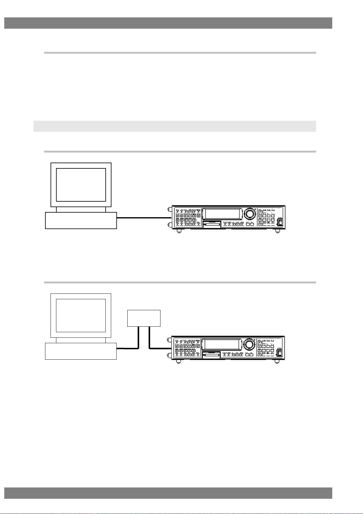
Host computer
VG-870
RS-232C straight
cable
Host computer
VG-870
Hub
1.2.2 LAN
Communication parameters
10BASE-T, 100BASE-TX
Connectors
RJ-45
1.3 Connection configuration
1.3.1 RS-232C
Fig. 1-3-1
1.3.2 LAN
Fig. 1-3-2
Page 17

Chapter 1 CONCERNING THE TERMINAL COMMANDS
3
Command
Function
Remarks
SPbPrD [92H]
Color difference coefficient data registration
PbPrDNAMES3 [93H]
Color difference coefficient data name registration
COLOR [26H]
Color bar color setting
GBITBLT [DAH]
1-bit plane copying
G8BITBLT [E9H]
Color planes (8-bit planes) copy
Extended command
Extended function command
1.4 Differences in commands from conventional VG
series
The following commands used by the old VG models are not supported by the VG-870.
Page 18
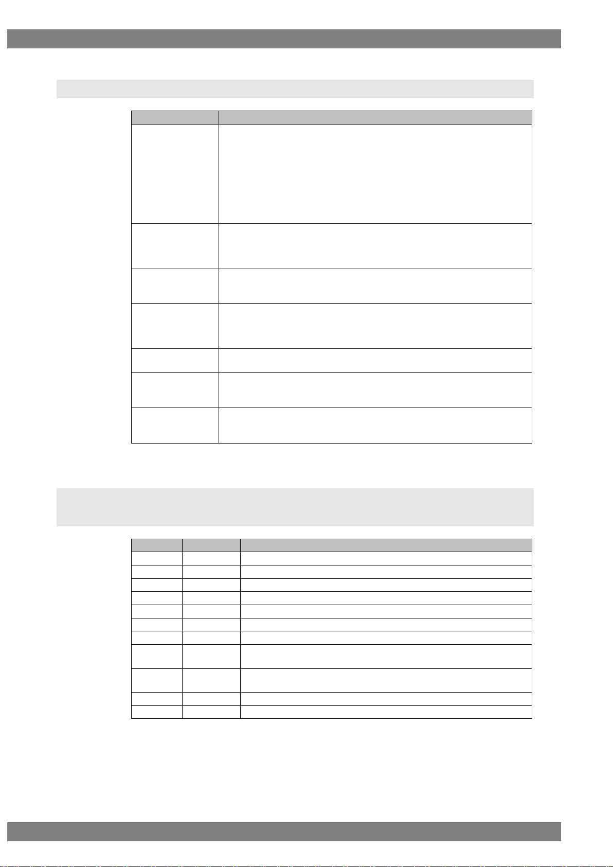
4
Term
Description
Auto display data
The length of the interval (in seconds) after the patterns have been output
until the next program is run as well as the sequence of the numbers of the
programs to be run when the VG generator is operated in the auto display
mode are set as parameters.
The sequence of program numbers can be set in a 3-block format. If, for
instance, program numbers 01, 02 and 03 are to be output first followed by
program numbers 07, 08 and 09 after which the programs are to be
repeated from 01, then 01-03 is set in the first block, 07-09 is set in the
second block, and 00-00 is set in the third block.
Pattern select data
This data is for selecting which pattern is to be output if programs are run
when the VG generator is operated in the direct display or auto display
mode. Bear in mind that “R, “, “G” and “B” must be entered in the data:
otherwise, the data will be registered without color.
Buffer RAM
The VG generator calls one of the programs registered on the Compact
Flash card (or internal flash memory) to its execution RAM first, and it then
executes the contents of the program. This RAM is called the buffer RAM.
1-program data
This is the increment of the data which is registered on the Compact Flash
card (or internal flash memory). The 1-program data consists of the H
timing data, V timing data, output condition data, pattern select data and
various pattern data.
User character
This refers to the characters which can be created and registered by the
user. The size of these characters is 64 by 64 dots.
Character plane
This is the plane on which 1-bit drawing with a single color is accomplished.
* It was referred to as the “graphic plane” in the previous terminal
commands.
Graphic plane
This is the plane on which drawings with 256 colors are displayed.
* It was referred to as the “color plane” in the previous terminal
commands.
Character
HEX code
Description
ENQ
05H
Request to start terminal mode
EOT
04H
Request to end terminal mode
ACK
06H
Positive acknowledge character
NAK
15H
Negative acknowledge character
STX
02H
Transmission text (command) start
ETB
17H
Transmission text (data) end
ETX
03H
Transmission text (command, data) end
TRDT
10H
When data is to be transmitted, this command is placed at the head of
the block before it is transmitted.
ESTS
11H
When an error status is to be transmitted, an error number is
transmitted with this command preceding it.
EXTCMD
FFH
Extended command identification code (* Added with old VG models)
VG4CMD
FDH
New command identification code
1.5 Description of terms used
Fig. 1-5
1.6 Transmission control characters, data and error
commands
Fig. 1-6
Page 19
Chapter 1 CONCERNING THE TERMINAL COMMANDS
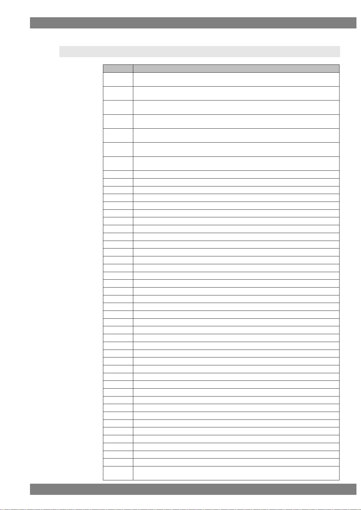
5
Error code
Description
“00”
This error occurs when an attempt has been made to write data when the memory
card was not installed.
“01”
This error occurs when the program which was input is disabled when direct display
or a program was executed.
“02”
This error occurs when the horizontal sync data is outside the 5.00 MHz ≤ Dot Clock
≤ 300.00 MHz range when direct display or a program was executed.
“03”
This error occurs when the horizontal sync data is outside the H Period ≥ Hsync +
Hbackp + Hdisp (dot) range when direct display or a program was executed.
“04”
This error occurs when the horizontal sync data is outside the H Period ≥ Hsync +
Hbackp + Hdisp (μs) range when direct display or a program was executed.
“05”
This error occurs when the horizontal sync data is outside the H Period ≥ HDstart +
HDwidth (dot) range when direct display or a program was executed.
“06”
This error occurs when the horizontal sync data is outside the H Period ≥ HDstart +
HDwidth (μs) range when direct display or a program was executed.
“16”
This error occurs when the correct data was not set in the output condition data.
“17”
This error occurs when the correct data was not set in the character pattern data.
“18”
This error occurs when the correct data was not set in the crosshatch pattern data.
“19”
This error occurs when the correct data was not set in the dot pattern data.
“20”
This error occurs when the correct data was not set in the circle pattern data.
“21”
This error occurs when the correct data was not set in the burst pattern data.
“22”
This error occurs when the correct data was not set in the window pattern data.
“23”
This error occurs when the correct data was not set in the color bar pattern data.
“24”
This error occurs when there is an error in a parameter.
“25”
This error occurs when there is an error in the data.
“26”
This error occurs when the sync signals have not been set.
“27”
There is an error in the video level and sync level data.
“30”
A timeout occurred during communication in the terminal mode.
“31”
An undefined command was received in the terminal mode.
“32”
A timeout occurred in vertical sync interrupt wait.
“33”
There is an error in the program number.
“34”
There is an error in the group number.
“35”
There is an error in the user character code.
“40”
The memory card has not been installed.
“43”
There is an error in the optional pattern number.
“44”
Trouble with FAT for optional patterns created by the user
“45”
Unregistered optional pattern created by the user
“46”
There is an error in the image data number.
“47”
Trouble with FAT for image data
“48”
The image data has not been registered.
“50”
The function cannot be used because the keys are locked.
“51”
The cursor pattern has not been selected.
“52”
Invalid EDID optional pattern
“56”
There is an error in the gray scale pattern data.
“57”
There is an error in the optional pattern data.
“59”
There is an error in the cursor pattern data.
“60”
There is an error in the program name data.
“61”
There is an error in the graphic color data.
“62”
There is an error in the action data.
“64”
Vtotal of the vertical timing data is outside the specified range.
“65”
Vdisp of the vertical timing data is outside the specified range.
“66”
Vsync of the vertical timing data is outside the specified range.
“67”
Vbackp of the vertical timing data is outside the specified range.
“68”
The front porch of the vertical timing data is outside the specified range. (Vtotal ≥
Vsync + Vbackp + Vdisp)
1.7 Error statuses
Page 20
6
“69”
The blanking period of the vertical timing data is outside the specified range.
“70”
The vertical frequency of the vertical timing data is outside the specified range.
“71”
VDstart + VDline of the vertical timing data are outside the specified range. (Vtotal ≥
VDstart + VDline)
“72”
EQPfp of the vertical timing data is outside the specified range.
“73”
EQPbp of the vertical timing data is outside the specified range.
“74”
An error other than the ones above occurred in the vertical timing data.
“75”
A timeout occurred in DDC1.
“76”
An ACK error occurred in DDC1.
“78”
An ACK error occurred in DDC2.
“80”
An error occurred in Macrovision.
“81”
An error occurred in a simple moving image.
“82”
There is an error in the header information of the EDID data.
“83”
Check sum error in the EDID data.
“84”
There is an error in the header information and check sum of the EDID data.
“85”
There is an error in the YPbPr coefficients.
“86”
There is an error in the audio data number.
“87”
Trouble in FAT for the audio data
“88”
Unregistered audio data
“90”
The wrong EDID port is used for lip sync.
“91”
The delay time for lip sync was set longer than the ON (or OFF) time.
“92”
Invalid EDID latency for lip sync.
“93”
A setting other than Inter-PCM/DCD has been selected for Audio Source for lip sync
or it is set to Sweep.
Fig. 1-7
Page 21
Chapter 1 CONCERNING THE TERMINAL COMMANDS
7
STX
VG4CMD
Command 1
Command 2
ETX
STX
VG4CMD
Command 1
Command 2
Parameters
ETX
STX
Command
ETX
STX
Command
Parameters
ETX
STX
EXTCMD
Model code
Command
ETX
STX
EXTCMD
Model code
Command
Parameters
ETX
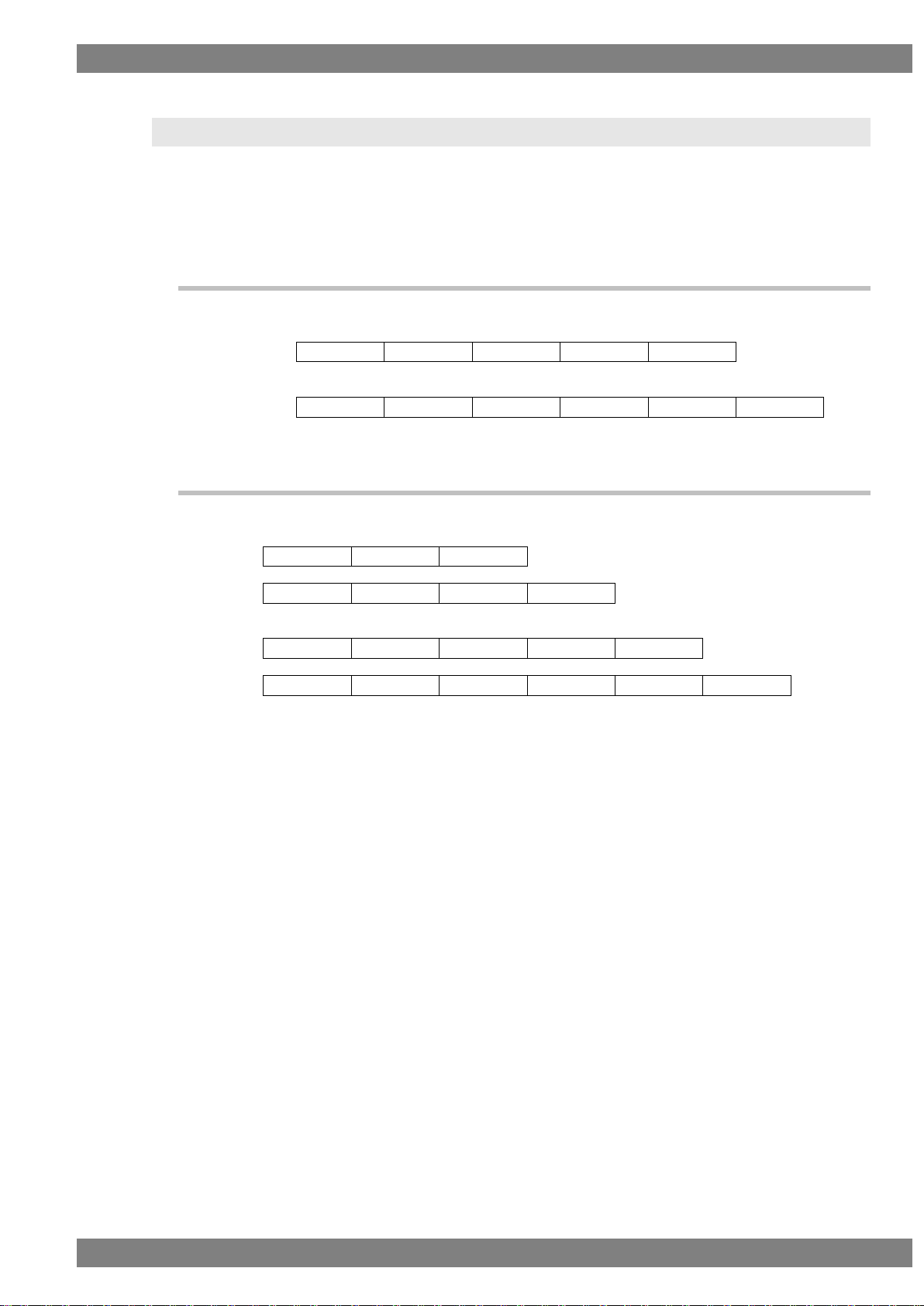
1.8 Command formats
Two types of formats are used for the commands sent to the VG generator: the new commands
and old commands. There are two types of old commands: ones which are compatible with the VG
generators available in the past, and the extended commands which are used by the VG-848
series.
1.8.1 New commands
(1) Without parameters
(2) With parameters
VG4CMD: New command identification code (FDH)
1.8.2 Old commands
Compatible commands (Conventional commands)
or
Extended commands (* Used by the VG-848 series)
or
EXTCMD: Extended command identification code (FFH)
Model codes: VG generator model codes
(47H = VG-848, 48H = VG-835, 49H = VG-849/849A/849B, 4AH = VG-858,
4BH = VG-830, 4CH = VG-857, 4DH = VG-859/859A/859B, 4EH = VG-837,
4FH = VG-835-A, 50H = VG-849C, 51H = VG-859C, 52H = VG-835-B,
53H = VG-849C-A)
Page 22
8
STX
VG4CMD
Command 1
Command 2
ETX
STX
VG4CMD
Command 1
Command 2
Parameters
ETX
ACK
STX
ESTS
Error code
ETX
STX
TRDT
Data
ETB
STX
TRDT
Data
ETX
ACK
STX
ESTS
Error code
ETX
STX
VG4CMD
Command 1
Command 2
ETX
STX
VG4CMD
Command 1
Command 2
Parameters
ETX
ACK
STX
ESTS
Error code
ETX
STX
TRDT
Data
ETB
STX
TRDT
Data
ETX
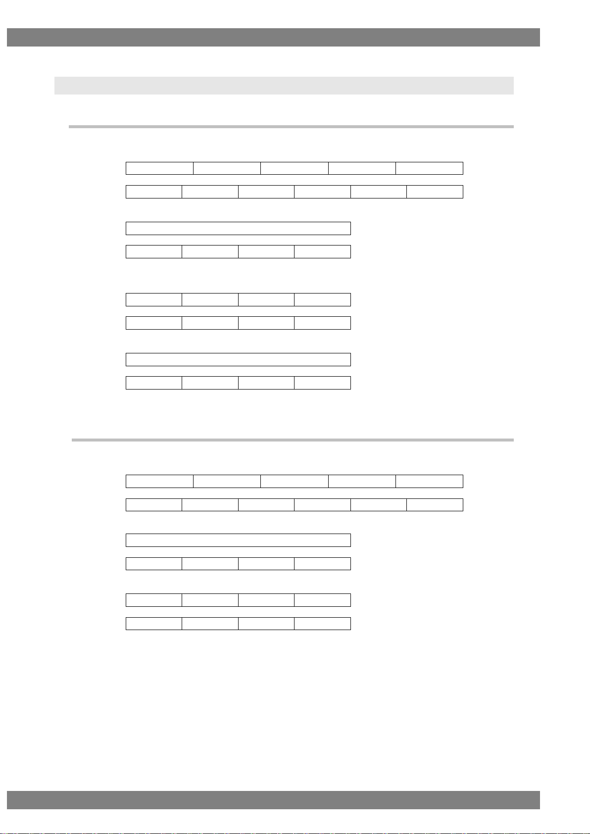
1.9 Basic formats
1.9.1 When setting commands are sent
Command transmission from computer to VG generator (PC → VG)
or
Return value from VG generator to computer after command transmission (PC ← VG)
or
When data is required, transmission is as shown below only when the commands were
sent and ACK was returned. (PC → VG)
or
Return value from VG generator to computer after data transmission (PC ← VG)
or
Fig. 1-9-1
1.9.2 When the get command is sent
Command transmission from computer to VG generator (PC → VG)
or
Return value from VG generator to computer after command transmission (PC ← VG)
or
Reception is as shown below only when ACK is returned. (PC ← VG)
or
Fig. 1-9-2
Page 23
Chapter 1 CONCERNING THE TERMINAL COMMANDS
9
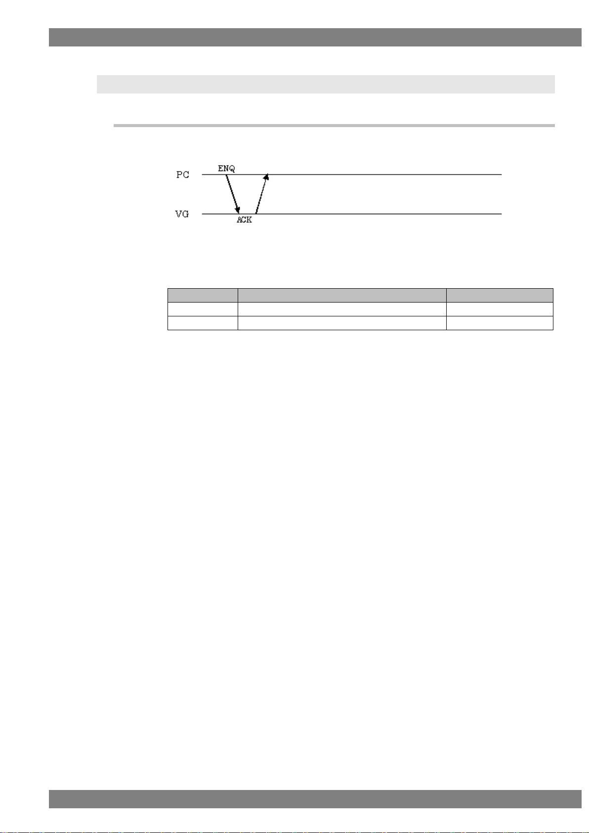
Flow
Command
Send/receive direction 1 ENQ
Send
2
ACK
Receive
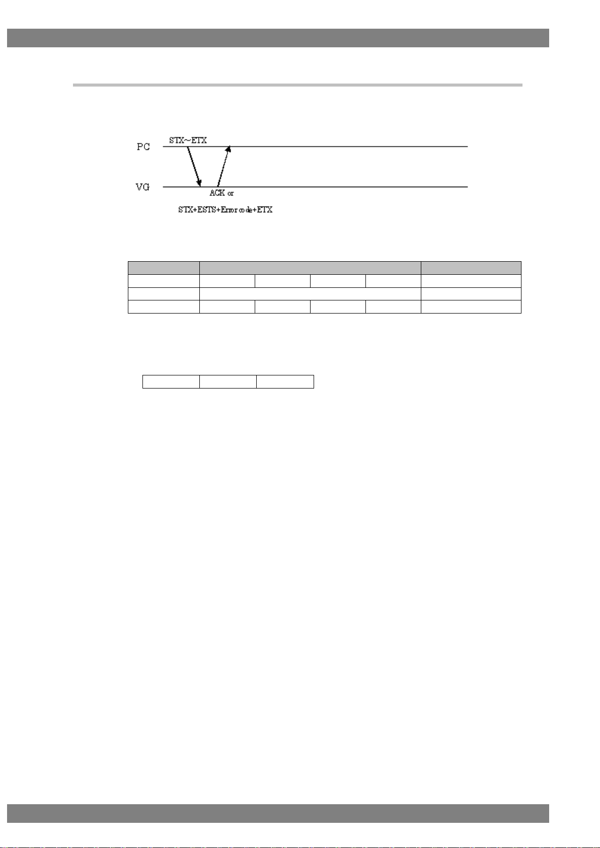
1.10 Communication protocol
1.10.1 Type 1
This is the sequence when the terminal commands are started.
Fig. 1-10-1-1
Fig. 1-10-1-2
Page 24
10
Flow
Command
Send/receive direction
1
STX
Command*
(Parameters)
ETX
Send
2a (Successful)
ACK
Receive
2b (Failed)
STX
ESTS
Error code
ETX
Receive
VG4CMD
Command 1
Command 2
1.10.2 Type 2
This is the sequence when commands consisting of only a command and parameters (if
required) only are transmitted.
Fig. 1-10-2-1
Fig. 1-10-2-2
* It is assumed here that the following three codes are entered in the command portion.
Page 25
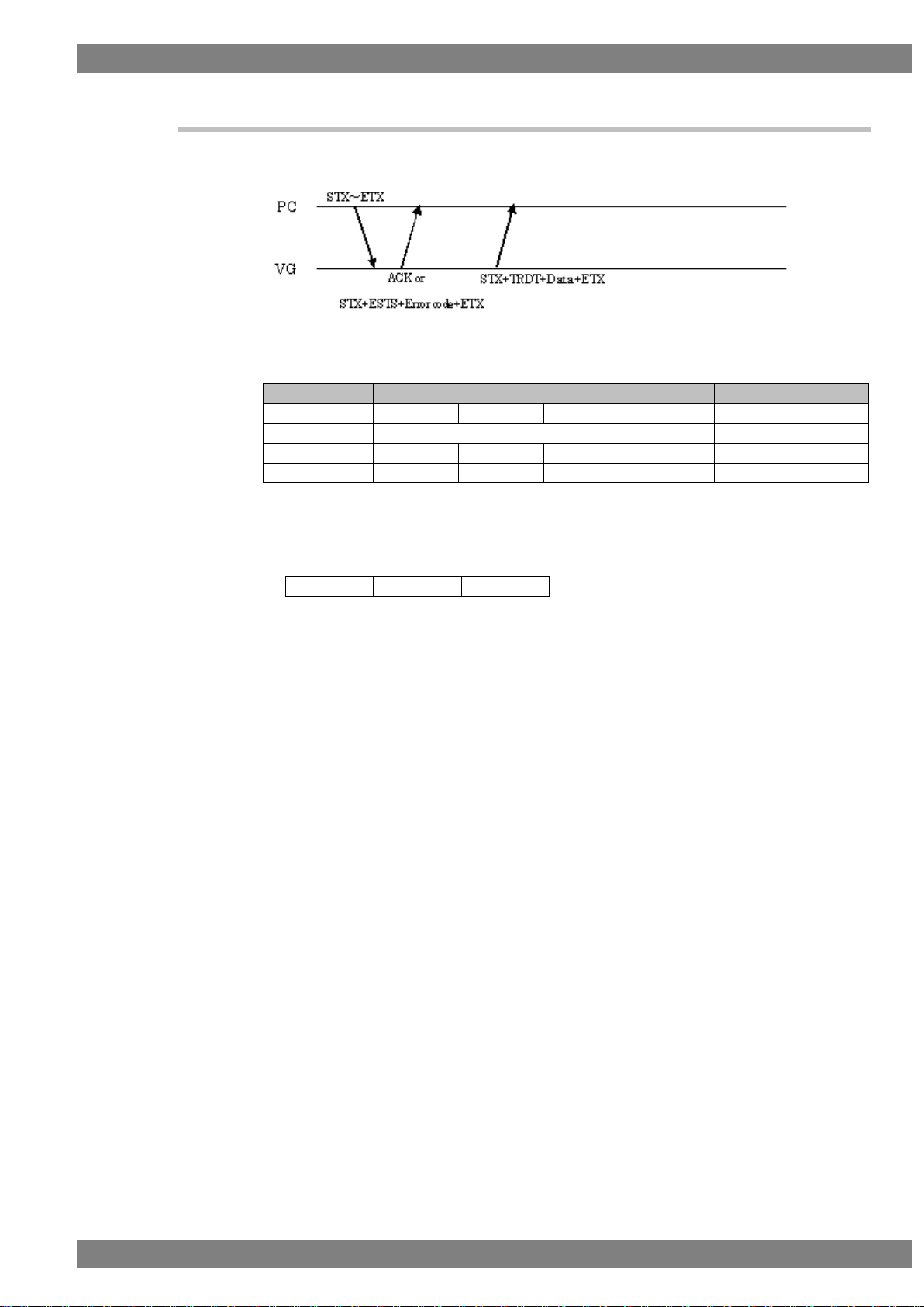
Chapter 1 CONCERNING THE TERMINAL COMMANDS
11
Flow
Command
Send/receive direction
1
STX
Command*1
(Parameters)
ETX
Send
2a (Successful)
ACK
Receive
2b (Failed)
STX
ESTS
Error code
ETX
Receive
3
STX
TRDT
Data
ETX
Receive
VG4CMD
Command 1
Command 2
1.10.3 Type 3
This is the sequence for receiving the VG data.
Fig. 1-10-3-1
Fig. 1-10-3-2
Note 1) It is assumed here that the following three codes are entered in the command portion.
Note 2) The flow is terminated at 2b if communication failed.
Page 26
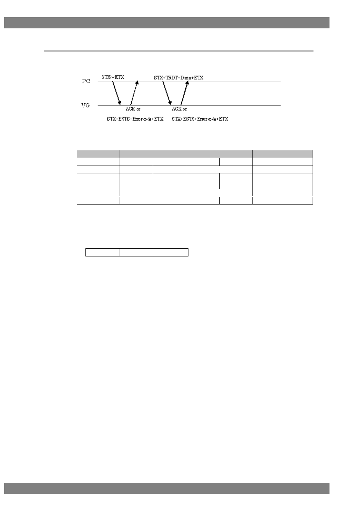
12
Flow
Command
Send/receive direction
1
STX
Command*1
(Parameters)
ETX
Send
2a (Successful)
ACK
Receive
2 b (Failed)
STX
ESTS
Error code
ETX
Receive
3
STX
TRDT
Data
ETX
Send
4a (Successful)
ACK
Receive
4b (Failed)
STX
ESTS
Error code
ETX
Receive
VG4CMD
Command 1
Command 2
1.10.4 Type 4
This is the sequence for sending the VG data.
Fig. 1-10-4-1
Fig. 1-10-4-2
Note1) It is assumed here that the following three codes are entered in the command
portion.
Note2) The flow is terminated at 2b if communication failed.
Page 27
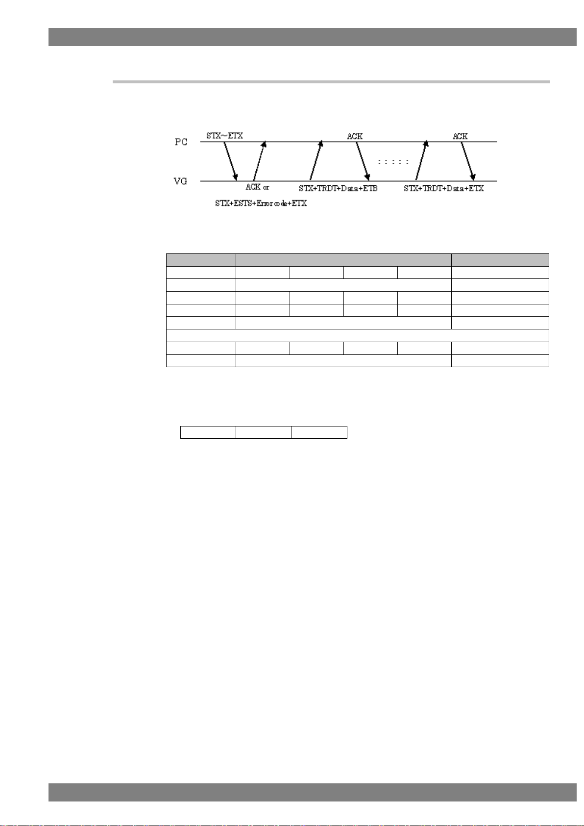
Chapter 1 CONCERNING THE TERMINAL COMMANDS
13
Flow
Command
Send/receive direction
1
STX
Command*1
(Parameters)
ETX
Send
2a (Successful)
ACK
Receive
2b (Failed)
STX
ESTS
Error code
ETX
Receive
3
STX
TRDT
Data
ETB
Receive
4
ACK
Send
3 and 4 are repeated for the desired number of times.
n-1
STX
TRDT
Data
ETX
Receive
n
ACK
Receive
VG4CMD
Command 1
Command 2
1.10.5 Type 5
This is the sequence for receiving the VG data. The data must be received for the
desired number of times.
Fig. 1-10-5-1
Fig. 1-10-5-2
Note1) It is assumed here that the following three codes are entered in the command portion.
Note 2) The flow is terminated at 2b if communication failed.
Page 28
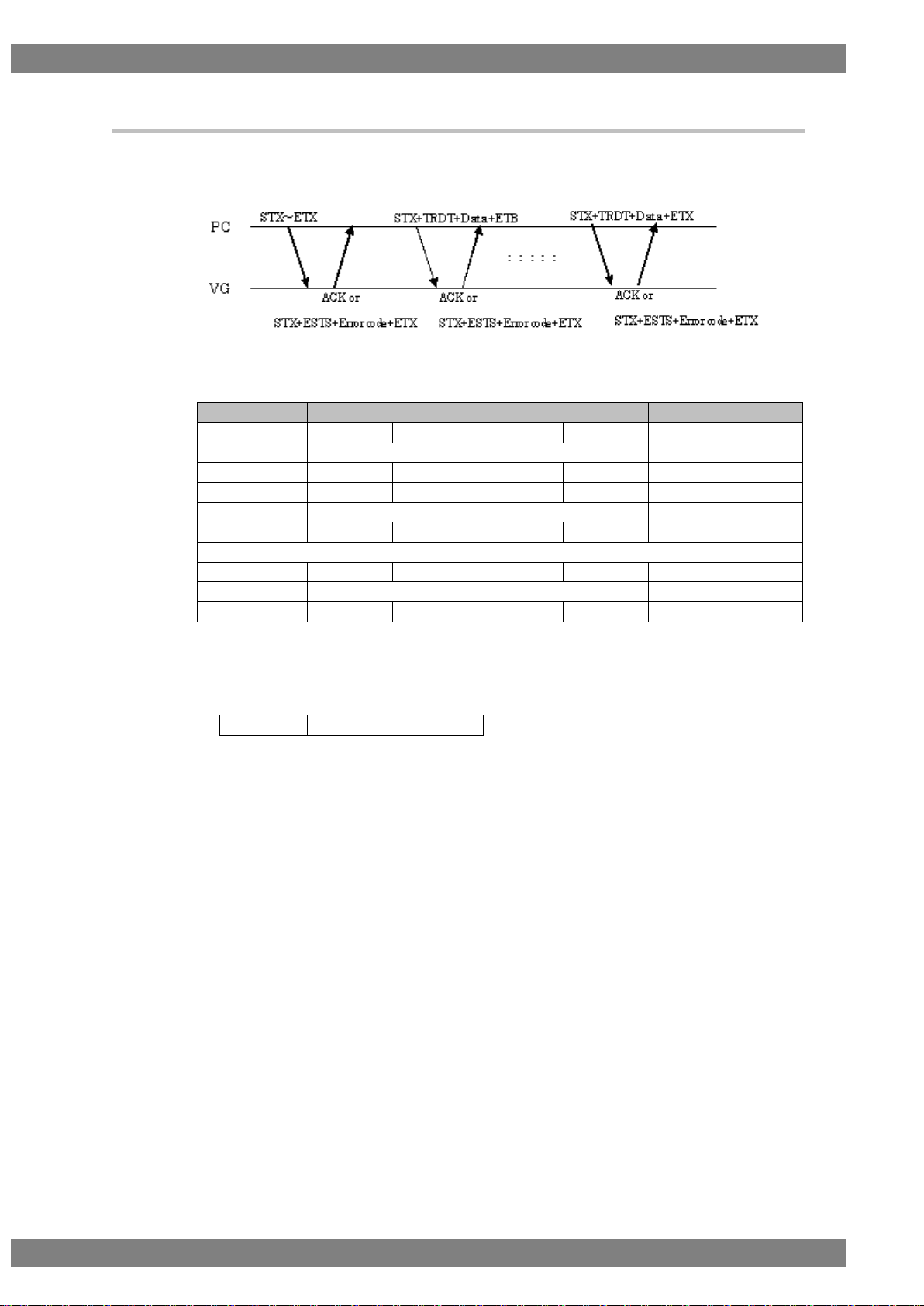
14
Flow
Command
Send/receive direction
1
STX
Command*1
(Parameters)
ETX
Send
2a (Successful)
ACK
Receive
2b (Failed)
STX
ESTS
Error code
ETX
Receive
3
STX
TRDT
Data
ETB
Send
4a (Successful)
ACK
Receive
4b (Failed)
STX
ESTS
Error code
ETX
Receive
3 and 4a or 4b are repeated for the desired number of times.
n-1
STX
TRDT
Data
ETX
Send
na (Successful)
ACK
Receive
nb (Failed)
STX
ESTS
Error code
ETX
Receive
VG4CMD
Command 1
Command 2
1.10.6 Type 6
This is the sequence for sending the VG data. The data must be sent for the desired
number of times.
Fig. 1-10-6-1
Fig. 1-10-6-2
Note1) It is assumed here that the following three codes are entered in the command portion.
Note2) The flow is terminated at 2b or 4b if communication failed.
Page 29
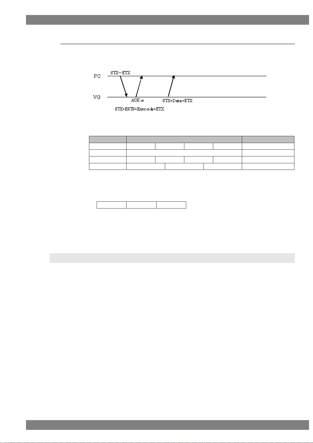
Chapter 1 CONCERNING THE TERMINAL COMMANDS
15
Flow
Command
Send/receive direction
1
STX
Command*1
(Parameters)
ETX
Send
2a (Successful)
ACK
Receive
2b (Failed)
STX
ESTS
Error code
ETX
Receive
3
STX
Data
ETX
Receive
VG4CMD
Command 1
Command2
1.10.7 Type 7
This is the sequence for receiving the VG data. Unlike with type 3, “TRDT” is not
received.
Fig. 1-10-7-1
Fig. 1-10-7-2
Note1) It is assumed here that the following three codes are entered in the command portion.
Note2) The flow is terminated at 2b if communication failed.
1.11 Precaution drawing command
Drawing command for graphic plane (in previous terminal command, it was referred as
color plane) please remind about following issues.
1. Pattern cannot be displayed with other pattern
If you execute the graphic plane drawing command when you are displaying pattern by
VG’s front panel or remote controller, for example color bar, pattern will be abnormal.
2. Before executing the graphic plane drawing command, please execute the clear
command (GRACLR4 {28H 40H}: Graphic plain clear).
3. Color table for graphic plain drawing command, will be 0 to 255.
Page 30

16
Page 31

17
2
2
INDIVIDUAL FORMATS FOR VG
CONTROL COMMANDS
STX
1 byte
02H
VG4CMD
1 byte
FDH
SHT4
2 bytes
20H 20H
Program number
1 to 4 bytes
“0” to “1000”, “9999”
,
1 byte
2CH (Delimiter)
μs/dot
1 byte
“0” = μs, “1” = dot
,
1 byte
2CH (Delimiter)
Repetition
1 to 2 bytes
“1” to “10”
,
1 byte
2CH (Delimiter)
DOT CLOCK
1 to 9 bytes
“0” to “999999999” (in 1 Hz increments)
,
1 byte
2CH (Delimiter)
H-PERIOD
1 to 5 bytes
“0” to “65535” (0 to 655.35 with μs)
,
1 byte
2CH (Delimiter)
H-DISPLAY
1 to 5 bytes
“0” to “65535” (0 to 655.35 with μs)
,
1 byte
2CH (Delimiter)
H-SYNC
1 to 5 bytes
“0” to “65535” (0 to 655.35 with μs)
,
1 byte
2CH (Delimiter)
H-BACK-PORCH
1 to 5 bytes
“0” to “65535” (0 to 655.35 with μs)
,
1 byte
2CH (Delimiter)
HD-START
1 to 5 bytes
“0” to “65535” (0 to 655.35 with μs)
,
1 byte
2CH (Delimiter)
HD-WIDTH
1 to 5 bytes
“0” to “65535” (0 to 655.35 with μs)
ETX
1 byte
03H
2.1 SHT4 [20H 20H]: H timing data registration
Function: This command registers the H timing data of the program whose number
has been designated. When the program number is 0, it writes the data into
the buffer RAM. When it is 9999, it writes the data into the command work
RAM.
Sequence: Type 2
Command:
Fig. 2-1-1
Page 32

18
STX
1 byte
02H
VG4CMD
1 byte
FDH
LHT4
2 bytes
20H 21H
Program number
1 to 4 bytes
“0” to “2000”, “9999”
ETX
1 byte
03H
STX
1 byte
02H
TRDT
1 byte
10H
μs/dot
1 byte
“0” = μs, “1” = dot
,
1 byte
2CH (Delimiter)
Repetition
1 to 2 bytes
“1” to “10”
,
1 byte
2CH (Delimiter)
DOT CLOCK
1 to 9 bytes
“0” to “999999999” (in 1 Hz increments)
,
1 byte
2CH (Delimiter)
H-PERIOD
1 to 5 bytes
“0” to “65535” (0 to 655.35 with μs)
,
1 byte
2CH (Delimiter)
H-DISPLAY
1 to 5 bytes
“0” to “65535” (0 to 655.35 with μs)
,
1 byte
2CH (Delimiter)
H-SYNC
1 to 5 bytes
“0” to “65535” (0 to 655.35 with μs)
,
1 byte
2CH (Delimiter)
H-BACK-PORCH
1 to 5 bytes
“0” to “65535” (0 to 655.35 with μs)
,
1 byte
2CH (Delimiter)
HD-START
1 to 5 bytes
“0” to “65535” (0 to 655.35 with μs)
,
1 byte
2CH (Delimiter)
HD-WIDTH
1 to 5 bytes
“0” to “65535” (0 to 655.35 with μs)
ETX
1 byte
03H
2.2 LHT4 [20H 21H]: H timing data readout
Function: This command reads the H timing data of the program whose number has
been designated. When the program number is 0, it reads out the data from
the buffer RAM. When the program has any number from 1001 to 2000, the
command reads out from the fixed data. When the program number is 9999,
the command reads the data from the command work RAM.
Sequence: Type 3
Command:
Fig. 2-2-1
Data:
Fig. 2-2-2
Page 33

Chapter 2 INDIVIDUAL FORMATS FOR VG CONTROL COMMANDS
19
STX
1 byte
02H
VG4CMD
1 byte
FDH
SVT4
2 bytes
20H 22H
Program number
1 to 4 bytes
“0” to “1000”, “9999”
,
1 byte
2CH (Delimiter)
SCAN MODE
1 byte
“0” = NO INTER, “1” = INTER & sync,
“2” = INTER & VIDEO,
“3” = Progressive Segmented Frame
,
1 byte
2CH (Delimiter)
SERRATION
1 byte
“0” = OFF, “1” = 0.5H, “2” = 1H, “3” = EXOR
,
1 byte
2CH (Delimiter)
ENQ ON/OFF
1 byte
“0” = OFF, “1” = ON
,
1 byte
2CH (Delimiter)
V-TOTAL
1 to 5 bytes
“0” to “99995” (0 to 9999.5H)
,
1 byte
2CH (Delimiter)
V-SYNC
1 to 3 bytes
“0” to “995” (0 to 99.5H) * In 0.5H increments
,
1 byte
2CH (Delimiter)
ENQ-FP
1 to 3 bytes
“0” to “995” (0 to 99.5H) * In 0.5H increments
,
1 byte
2CH (Delimiter)
ENQ-BP
1 to 3 bytes
“0” to “995” (0 to 99.5H) * In 0.5H increments
,
1 byte
2CH (Delimiter)
V-BACK-PORCH
1 to 5 bytes
“0” to “99995” (0 to 9999.5H)
,
1 byte
2CH (Delimiter)
V-DISPLAY
1 to 4 bytes
“0” to “9999” (0 to 9999H)
,
1 byte
2CH (Delimiter)
VD-START
1 to 5 bytes
“0” to “99995” (0 to 9999.5H) * In 0.5H increments
,
1 byte
2CH (Delimiter)
VD-WIDTH
1 to 5 bytes
“0” to “99995” (0 to 9999.5H) * In 0.5H increments
,
1 byte
2CH (Delimiter)
V-TOTAL2
1 to 5 bytes
“0” to “99995” (0 to 9999.5H)
,
1 byte
2CH (Delimiter)
V-SYNC2
1 to 3 bytes
“0” to “995” (0 to 99.5H) * In 0.5H increments
,
1 byte
2CH (Delimiter)
ENQ-FP2
1 to 3 bytes
“0” to “995” (0 to 99.5H) * In 0.5H increments
,
1 byte
2CH (Delimiter)
ENQ-BP2
1 to 3 bytes
“0” to “995” (0 to 99.5H) * In 0.5H increments
,
1 byte
2CH (Delimiter)
V-BACK-PORCH2
1 to 5 bytes
“0” to “99995” (0 to 9999.5H)
,
1 byte
2CH (Delimiter)
V-DISPLAY2
1 to 4 bytes
“0” to “9999” (0 to 9999H)
,
1 byte
2CH (Delimiter)
VD-START2
1 to 5 bytes
“0” to “99995” (0 to 9999.5H) * In 0.5H increments
,
1 byte
2CH (Delimiter)
VD-WIDTH2
1 to 5 bytes
“0” to “99995” (0 to 9999.5H) * In 0.5H increments
,
1 byte
2CH (Delimiter)
2.3 SVT4 [20H 22H]: V timing data registration
Function: This command registers the V timing data of the program whose number
has been designated. When the program number is 0, it writes the data into
the buffer RAM. When it is 9999, it writes the data into the command work
RAM.
Sequence: Type 2
Command:
Page 34

20
TV Mode
1 to 2 bytes
“0” = Other
“1” = NTSC
“2” = PAL
“3” = SECAM
“4” = HDTV1080
“5” = Reserved
“6” = NTSC-M
“7” = NTSC-443
“8” = PAL-M
“9” = PAL-60
“10” = PAL-N
“11” = PAL-Nc
“12” = HDTV1250AUS
“13” = HDTV1250
“14” = HDTV1152AUS
“15” = Reserved
“16” = Reserved
“17” = HDTV720
,
1 byte
2CH (Delimiter)
Reserved
32 bytes
Reserved (fixed to all 0)
ETX
1 byte
03H
Fig. 2-3-1
Page 35

Chapter 2 INDIVIDUAL FORMATS FOR VG CONTROL COMMANDS
21
STX
1 byte
02H
VG4CMD
1 byte
FDH
LHT4
2 bytes
20H 23H
Program number
1 to 4 bytes
“0” to “2000”, “9999”
ETX
1 byte
03H
STX
1 byte
02H
TRDT
1 byte
10H
SCAN MODE
1 byte
“0” = NO INTER, “1” = INTER & sync,
“2” = INTER & VIDEO,
“3” = Progressive Segmented Frame
,
1 byte
2CH (Delimiter)
SERRATION
1 byte
“0” = OFF, “1” = 0.5H, “2” = 1H, “3” = EXOR
,
1 byte
2CH (Delimiter)
ENQ ON/OFF
1 byte
“0” = OFF, “1” = ON
,
1 byte
2CH (Delimiter)
V-TOTAL
1 to 5 bytes
“0” to “99995” (0 to 9999.5H)
,
1 byte
2CH (Delimiter)
V-SYNC
1 to 3 bytes
“0” to “995” (0 to 99.5H) * In 0.5H increments
,
1 byte
2CH (Delimiter)
ENQ-FP
1 to 3 bytes
“0” to “995” (0 to 99.5H) * In 0.5H increments
,
1 byte
2CH (Delimiter)
ENQ-BP
1 to 3 bytes
“0” to “995” (0 to 99.5H) * In 0.5H increments
,
1 byte
2CH (Delimiter)
V-BACK-PORCH
1 to 5 bytes
“0” to “99995” (0 to 9999.5H)
,
1 byte
2CH (Delimiter)
V-DISPLAY
1 to 4 bytes
“0” to “9999” (0 to 9999H)
,
1 byte
2CH (Delimiter)
VD-START
1 to 5 bytes
“0” to “99995” (0 to 9999.5H) * In 0.5H increments
,
1 byte
2CH (Delimiter)
VD-WIDTH
1 to 5 bytes
“0” to “99995” (0 to 9999.5H) * In 0.5H increments
,
1 byte
2CH (Delimiter)
V-TOTAL2
1 to 5 bytes
“0” to “99995” (0 to 9999.5H)
,
1 byte
2CH (Delimiter)
V-SYNC2
1 to 3 bytes
“0” to “995” (0 to 99.5H) * In 0.5H increments
,
1 byte
2CH (Delimiter)
ENQ-FP2
1 to 3 bytes
“0” to “995” (0 to 99.5H) * In 0.5H increments
,
1 byte
2CH (Delimiter)
ENQ-BP2
1 to 3 bytes
“0” to “995” (0 to 99.5H) * In 0.5H increments
,
1 byte
2CH (Delimiter)
V-BACK-PORCH2
1 to 5 bytes
“0” to “99995” (0 to 9999.5H)
,
1 byte
2CH (Delimiter)
V-DISPLAY2
1 to 4 bytes
“0” to “9999” (0 to 9999H)
2.4 LVT4 [20H 23H]: V timing data readout
Function: This command reads the V timing data of the program whose number has
been designated. When the program number is 0, it reads out the data from
the buffer RAM. When the program has any number from 1001 to 2000, the
command reads out from the fixed data. When the program number is 9999,
the command reads the data from the command work RAM.
Sequence: Type 3
Command:
Data:
Fig. 2-4-1
Page 36

22
,
1 byte
2CH (Delimiter)
VD-START2
1 to 5 bytes
“0” to “99995” (0 to 9999.5H) * In 0.5H increments
,
1 byte
2CH (Delimiter)
VD-WIDTH2
1 to 5 bytes
“0” to “99995” (0 to 9999.5H) * In 0.5H increments
,
1 byte
2CH (Delimiter)
TV Mode
1 or 2 bytes
“0” = Other
“1” = NTSC
“2” = PAL
“3” = SECAM
“4” = HDTV1080
“5” = Reserved
“6” = NTSC-M
“7” = NTSC-443
“8” = PAL-M
“9” = PAL-60
“10” = PAL-N
“11” = PAL-Nc
“12” = HDTV1250AUS
“13” = HDTV1250
“14” = HDTV1152AUS
“15” = Reserved
“16” = Reserved
“17” = HDTV720
,
1 byte
2CH (Delimiter)
Reserved
32 bytes
Reserved (All 0)
ETX
1 byte
03H
Fig. 2-4-2
Page 37

Chapter 2 INDIVIDUAL FORMATS FOR VG CONTROL COMMANDS
23
STX
1 byte
02H
VG4CMD
1 byte
FDH
SOT4
2 bytes
20H 24H
Program number
1 to 4 bytes
“0” to “1000”, “9999”
,
1 byte
2CH (Delimiter)
YPbPr
1 byte
“0” = OFF (RGB), “1” = ON (YPbPr)
,
1 byte
2CH (Delimiter)
YPbPrNo
1 byte
“0” to “5”
0 to 3, 5: Fixed data is used.
4: The values in coefficient tables below are used.
,
1 byte
2CH (Delimiter)
Color difference
coefficient YR
1 to 5 bytes
“0” to “10000”
Total value of YG + YB must be set to under 10000.
,
1 byte
2CH (Delimiter)
Color difference
coefficient YG
1 to 5 bytes
“0” to “10000”
Total value of YR + YB must be set to under 10000.
,
1 byte
2CH (Delimiter)
Color difference
coefficient YB
1 to 5 bytes
“0” to “10000”
Total value of YR + YG must be set to under 10000.
,
1 byte
2CH (Delimiter)
Color difference
coefficient CbR
1 to 4 bytes
“0” to “5000”
Total value of CbG + CbB must be set to under 10000.
,
1 byte
2CH (Delimiter)
Color difference
coefficient CbG
1 to 4 bytes
“0” to “5000”
Total value of CbR + CbB must be set to under 10000.
,
1 byte
2CH (Delimiter)
Color difference
coefficient CbB
1 to 4 bytes
“0” to “5000”
Total value of CbR + CbG must be set to under 10000.
,
1 byte
2CH (Delimiter)
Color difference
coefficient CrR
1 to 4 bytes
“0” to “5000”
Total value of CrR + CrG must be set to under 10000.
,
1 byte
2CH (Delimiter)
Color difference
coefficient CrG
1 to 4 bytes
“0” to “5000”
Total value of CrR + CrB must be set to under 10000.
,
1 byte
2CH (Delimiter)
Color difference
coefficient CrB
1 to 4 bytes
“0” to “5000”
Total value of CrR + CrG must be set to under 10000.
,
1 byte
2CH (Delimiter)
HS ON/OFF
1 byte
“0” = OFF, “1” = ON
,
1 byte
2CH (Delimiter)
HS MODE
1 byte
“0” = Nega, “1” = Posi
,
1 byte
2CH (Delimiter)
HS Sel
1 byte
“0” = HS, “1” = CS
,
1 byte
2CH (Delimiter)
VS ON/OFF
1 byte
“0” = OFF, “1” = ON
,
1 byte
2CH (Delimiter)
VS MODE
1 byte
“0” = Nega, “1” = Posi
2.5 SOT4 [20H 24H]: Output condition data registration
Function: This command registers the output condition data of the program whose
number has been designated. When the program number is 0, it writes the
data into the buffer RAM. When it is 9999, it writes the data into the
command work RAM.
Sequence: Type 2
Command:
Page 38

24
,
1 byte
2CH (Delimiter)
CS ON/OFF
1 byte
“0” = OFF, “1” = ON
,
1 byte
2CH (Delimiter)
CS MODE
1 byte
“0” = Nega, “1” = Posi
,
1 byte
2CH (Delimiter)
CS Sel
1 byte
“0” = CS, “1” = HS, “2” = VS
,
1 byte
2CH (Delimiter)
CV ON/OFF
1 byte
“0” = OFF, “1” = ON
,
1 byte
2CH (Delimiter)
CV MODE
1 byte
“1” = R, “2” = G, “3” = RG, “4” = B, “5” = RB, “6” = GB,
“7” = “RGB”
,
1 byte
2CH (Delimiter)
Analog Video Level
1 to 3 bytes
“0” to “120” (0.00 to 1.20 V)
,
1 byte
2CH (Delimiter)
Analog Setup Level
1 to 3 bytes
“0” to “25” (0.00 to 0.25 V)
,
1 byte
2CH (Delimiter)
Analog Sync Level
1 to 3 bytes
“0” to “60” (0.00 to 0.60 V)
,
1 byte
2CH (Delimiter)
Out Bit Len
1 or 2 bytes
“0” to “16”
* “0” to “12” in case of VG-882 and VG-883
0: Config setting is followed.
,
1 byte
2CH (Delimiter)
HDCP Disp Port
1 byte
“0” = Disable
“1” = DVI
“2” = PC (DVI)
“3” = HDMI1
“4” = HDMI2
"5" = TV-DVI
"6"=DisplayPort1
"7"=DisplayPort2
"8"=iTMDS1-1
"9"=iTMDS1-2
"10"=iTMDS2-1
"11"=iTMDS2-2
"12"=HDMI3 * VG-882,883, 876
"13"=HDMI4 * VG-882,883, 876
Below is for VG-876
"14"=HDMI5 "15"=HDMI6 "16"=HDMI7
"17"=HDMI8 "18"=HDMI9 "19"=HDMI10
"20"=HDMI11 "21"=HDMI12 "22"=HDMI13
"23"=HDMI14 "24"=HDMI15 "25"=HDMI16
"26"=DisplayPort3 "27"=DisplayPort4
"28"=DisplayPort5 "29"=DisplayPort6
"30"=DisplayPort7 "31"=DisplayPort8
,
1 byte
2CH (Delimiter)
D-Connector Line1
1 byte
“0” = 480, “1” = 720, “2” = 1080, "3" = Auto
,
1 byte
2CH (Delimiter)
D-Connector Line2
1 byte
“0” = Interlace, “1" = Progressive, "2" = Auto
,
1 byte
2CH (Delimiter)
D-Connector Line3
1 byte
“0” = 4:3, “1” = 4:3LB, “2” = 16:9, "3" = Auto
,
1 byte
2CH (Delimiter)
Reserved
1 byte
Fixed at “0”
,
1 byte
2CH (Delimiter)
PC-BNC ON/OFF
1 byte
“0” = OFF, “1” = ON
,
1 byte
2CH (Delimiter)
PC-DSub ON/OFF
1 byte
“0” = OFF, “1” = ON
,
1 byte
2CH (Delimiter)
DVI-A ON/OFF
1 byte
“0” = OFF, “1” = ON
,
1 byte
2CH (Delimiter)
DVI-D ON/OFF
1 byte
“0” = OFF, “1” = ON
,
1 byte
2CH (Delimiter)
VBS ON/OFF
1 byte
“0” = OFF, “1” = ON
, 2CH (Delimiter)
BNC ON/OFF
1 byte
“0” = OFF, “1” = ON
, 2CH (Delimiter)
Page 39

Chapter 2 INDIVIDUAL FORMATS FOR VG CONTROL COMMANDS
25
S-Connector ON/OFF
1 byte
“0” = OFF, “1” = ON
, 2CH (Delimiter)
D-Connector ON/OFF
1 byte
“0” = OFF, “1” = ON
,
1 byte
2CH (Delimiter)
TV-DSUB ON/OFF
1 byte
“0” = OFF, “1” = ON
,
1 byte
2CH (Delimiter)
SCART1 ON/OFF
1 byte
“0” = OFF, “1” = ON
,
1 byte
2CH (Delimiter)
SCART2 ON/OFF
1 byte
“0” = OFF, “1” = ON
,
1 byte
2CH (Delimiter)
HDMI1 ON/OFF
1 byte
“0” = OFF, “1” = ON
,
1 byte
2CH (Delimiter)
HDMI2 ON/OFF
1 byte
“0” = OFF, “1” = ON
,
1 byte
2CH (Delimiter)
DVI-D1 ON/OFF
1 byte
“0” = OFF, “1” = ON
,
1 byte
2CH (Delimiter)
DVI-D2 ON/OFF
1 byte
“0” = OFF, “1” = ON
,
1 byte
2CH (Delimiter)
LVDS-D1 ON/OFF
1 byte
“0” = OFF, “1” = ON
* LVDS1 and LVDS2 are the same.
,
1 byte
2CH (Delimiter)
LVDS-D2 ON/OFF
1 byte
“0” = OFF, “1” = ON
* LVDS1 and LVDS2 are the same.
,
1 byte
2CH (Delimiter)
LVDS-D3 ON/OFF
1 byte
“0” = OFF, “1” = ON
* LVDS3 and LVDS4 are the same.
,
1 byte
2CH (Delimiter)
LVDS-D4 ON/OFF
1 byte
“0” = OFF, “1” = ON
* LVDS3 and LVDS4 are the same.
,
1 byte
2CH (Delimiter)
PARA1 ON/OFF
1 byte
“0” = OFF, “1” = ON
,
1 byte
2CH (Delimiter)
PARA2 ON/OFF
1 byte
“0” = OFF, “1” = ON
,
1 byte
2CH (Delimiter)
PARA3 ON/OFF
1 byte
“0” = OFF, “1” = ON
,
1 byte
2CH (Delimiter)
PARA4 ON/OFF
1 byte
“0” = OFF, “1” = ON
,
1 byte
2CH (Delimiter)
S-Connector
1 byte
“0” = Normal (4:3 normally output)
“1” = LetterBox
“2” = Sqeeze
"3" = Auto
,
1 byte
2CH (Delimiter)
DVI Dual Link Mode
1 byte
“0” = Single (Auto)
“1” = Dual (8 bits)
“2” = Single (8 bits)
“3” = Single (16 bits)
,
1 byte
2CH (Delimiter)
DVI Ctl0
1 byte
“0” = Low, “1” = High
,
1 byte
2CH (Delimiter)
DVI Ctl1
1 byte
“0” = Low, “1” = High
,
1 byte
2CH (Delimiter)
Aspect Mode
1 byte
“0” = 4:3
“1” = 16:9
“2” = Reso
“3” = User
"4" = 4:3 LB
,
1 byte
2CH (Delimiter)
Aspect H
1 to 3 bytes
“1” to “255”
,
1 byte
2CH (Delimiter)
Aspect V
1 to 3 bytes
“1” to “255”
,
1 byte
2CH (Delimiter)
HDCP Enable
1 byte
“0” = Disable, “1” = Enable
,
1 byte
2CH (Delimiter)
Level Mode1 (Reserved)
1 byte
Fixed at “0”
,
1 byte
2CH (Delimiter)
Level Mode2 (PC All)
1 byte
“0” = FULL, “1” = LIMITED
,
1 byte
2CH (Delimiter)
Page 40

26
Level Mode3 (TV All)
1 byte
“0” = FULL, “1” = LIMITED
,
1 byte
2CH (Delimiter)
Level Mode4 (Reserved)
1 byte
Fixed at “0”
,
1 byte
2CH (Delimiter)
Level Mode5 (DVI)
1 byte
“0” = FULL, “1” = LIMITED
,
1 byte
2CH (Delimiter)
Level Mode6 (LVDS)
1 byte
“0” = FULL, “1” = LIMITED
,
1 byte
2CH (Delimiter)
Level Mode7 (Parallel)
1 byte
“0” = FULL, “1” = LIMITED
,
1 byte
2CH (Delimiter)
Level Mode8 (HDMI)
1 byte
“0” = FULL, “1” = LIMITED
,
1 byte
2CH (Delimiter)
Level Mode9 (Reserved)
1 byte
Fixed at “0”
,
1 byte
2CH (Delimiter)
Level Mode10
(Reserved)
1 byte
Fixed at “0”
,
1 byte
2CH (Delimiter)
Level Mode11
(DisplayPort)
1 byte
"0"=FULL "1"=LIMITTED
,
1 byte
2CH (Delimiter)
Level Mode12
(Reserved)
1 byte
Fixed at “0”
,
1 byte
2CH (Delimiter)
Level Mode13
(Reserved)
1 byte
Fixed at “0”
,
1 byte
2CH (Delimiter)
Level Mode14(iTMDS)
1 BYTE
"0"=FULL "1"=LIMITTED
,
1 BYTE
2CH(Delimiter)
Level Mode15
(Reserved)
1 byte
Fixed at “0”
,
1 byte
2CH (Delimiter)
Level Mode16
(Reserved)
1 byte
Fixed at “0”
,
1 byte
2CH (Delimiter)
Signal Name Disp On
1 byte
“0” = OFF, “1” = ON
,
1 BYTE
2CH (Delimiter)
DisplayPort1 ON/OFF
1 BYTE
"0"=OFF "1"=ON
,
1 BYTE
2CH (Delimiter)
DisplayPort2 ON/OFF
1 BYTE
"0"=OFF "1"=ON
,
1 BYTE
2CH (Delimiter)
TV-DVI Digital ON/OFF
1 BYTE
"0"=OFF "1"=ON
iTMDS1 ON/OFF
1 BYTE
"0"=OFF "1"=ON
,
1 BYTE
2CH (Delimiter)
iTMDS2 ON/OFF
1 BYTE
"0"=OFF "1"=ON
,
1 BYTE
2CH (Delimiter)
SDI 1&2 ON/OFF
1 BYTE
"0"=OFF "1"=ON
,
1 BYTE
2CH (Delimiter)
SDI 3&4 ON/OFF
1 BYTE
"0"=OFF "1"=ON
,
1 BYTE
2CH (Delimiter)
Digital Video Level
1 - 5 BYTE
"0" to "65535"
* In case of VG-882, 883, it is "0" to"4095"
,
1 BYTE
2CH (Delimiter)
Digital Video Level Bit
Mode
1 - 2 BYTE
"8" - "16"
* In case of VG-882, 883, it is "8" - "12"
,
1 BYTE
2CH (Delimiter)
HDMI3 ON/OFF
1 BYTE
"0"=OFF "1"=ON
,
1 BYTE
2CH (Delimiter)
HDMI4 ON/OFF
1 BYTE
"0"=OFF "1"=ON
ETX
1 byte
03H
Fig. 2-5-1
Page 41

Chapter 2 INDIVIDUAL FORMATS FOR VG CONTROL COMMANDS
27
STX
1 byte
02H
VG4CMD
1 byte
FDH
LOT4
2 bytes
20H 25H
Program number
1 to 4 bytes
“0” to “2000”, “9999”
ETX
1 byte
03H
STX
1 byte
02H
YPbPr
1 byte
“0” = OFF (RGB), “1” = ON (YPbPr)
,
1 byte
2CH (Delimiter)
YPbPrNo
1 byte
“0” to “5”
0 to 3, 5: Fixed data is used.
4: The values in coefficient tables below are used.
,
1 byte
2CH (Delimiter)
Color difference
coefficient YR
1 to 5 bytes
“0” to “10000”
Total value of YG + YB must be set to under 10000.
,
1 byte
2CH (Delimiter)
Color difference
coefficient YG
1 to 5 bytes
“0” to “10000”
Total value of YR + YB must be set to under 10000.
,
1 byte
2CH (Delimiter)
Color difference
coefficient YB
1 to 5 bytes
“0” to “10000”
Total value of YR + YG must be set to under 10000.
,
1 byte
2CH (Delimiter)
Color difference
coefficient CbR
1 to 4 bytes
“0” to “5000”
Total value of CbG + CbB must be set to under 10000.
,
1 byte
2CH (Delimiter)
Color difference
coefficient CbG
1 to 4 bytes
“0” to “5000”
Total value of CbR + CbB must be set to under 10000.
,
1 byte
2CH (Delimiter)
Color difference
coefficient CbB
1 to 4 bytes
“0” to “5000”
Total value of CbR + CbG must be set to under 10000.
,
1 byte
2CH (Delimiter)
Color difference
coefficient CrR
1 to 4 bytes
“0” to “5000”
Total value of CrR + CrG must be set to under 10000.
,
1 byte
2CH (Delimiter)
Color difference
coefficient CrG
1 to 4 bytes
“0” to “5000”
Total value of CrR + CrB must be set to under 10000.
,
1 byte
2CH (Delimiter)
Color difference
coefficient CrB
1 to 4 bytes
“0” to “5000”
Total value of CrR + CrG must be set to under 10000.
,
1 byte
2CH (Delimiter)
HS ON/OFF
1 byte
“0” = OFF, “1” = ON
,
1 byte
2CH (Delimiter)
HS MODE
1 byte
“0” = Nega, “1” = Posi
2.6 LOT4 [20H 25H]: Output condition data readout
Function: This command reads the output condition data of the designated program.
When the program number is 0, it reads out the data from the buffer RAM.
When the program has any number from 1001 to 2000, the command reads
out from the fixed data. When the program number is 9999, the command
reads the data from the command work RAM.
Sequence: Type 3
Command:
Data:
Fig. 2-6-1
Page 42

28
,
1 byte
2CH (Delimiter)
HS Sel
1 byte
“0” = HS, “1” = CS
,
1 byte
2CH (Delimiter)
VS ON/OFF
1 byte
“0” = OFF, “1” = ON
,
1 byte
2CH (Delimiter)
VS MODE
1 byte
“0” = Nega, “1” = Posi
,
1 byte
2CH (Delimiter)
CS ON/OFF
1 byte
“0” = OFF, “1” = ON
,
1 byte
2CH (Delimiter)
CS MODE
1 byte
“0” = Nega, “1” = Posi
,
1 byte
2CH (Delimiter)
CS Sel
1 byte
“0” = CS, “1” = HS, “2” = VS
,
1 byte
2CH (Delimiter)
CV ON/OFF
1 byte
“0” = OFF, “1” = ON
,
1 byte
2CH (Delimiter)
CV MODE
1 byte
“1” = R, “2” = G, “3” = RG, “4” = B, “5” = RB, “6” = GB,
“7” = “RGB”
,
1 byte
2CH (Delimiter)
Analog Video Level
1 to 3 bytes
“0” to “120” (0.00 to 1.20 V)
,
1 byte
2CH (Delimiter)
Analog Setup Level
1 to 3 bytes
“0” to “25” (0.00 to 0.25 V)
,
1 byte
2CH (Delimiter)
Analog Sync Level
1 to 3 bytes
“0” to “60” (0.00 to 0.60 V)
,
1 byte
2CH (Delimiter)
Out Bit Len
1 or 2 bytes
“0” to “16”
* “0” to “12” in case of VG-882 and VG-883
0: Config setting is followed.
,
1 byte
2CH (Delimiter)
HDCP Disp Port
1 byte
“0” = Disable
“1” = DVI
“2” = PC (DVI)
“3” = HDMI1
“4” = HDMI2
"5" = TV-DVI
"6"=DisplayPort1
"7"=DisplayPort2
"8"=iTMDS1-1
"9"=iTMDS1-2
"10"=iTMDS2-1
"11"=iTMDS2-2
"12"=HDMI3 * VG-882,883,876
"13"=HDMI4 * VG-882,883,876
Below is for VG-876
"14"=HDMI5 "15"=HDMI6 "16"=HDMI7
"17"=HDMI8 "18"=HDMI9 "19"=HDMI10
"20"=HDMI11 "21"=HDMI12 "22"=HDMI13
"23"=HDMI14 "24"=HDMI15 "25"=HDMI16
"26"=DisplayPort3 "27"=DisplayPort4
"28"=DisplayPort5 "29"=DisplayPort6
"30"=DisplayPort7 "31"=DisplayPort8
,
1 byte
2CH (Delimiter)
D-Connector Line1
1 byte
“0” = 480, “1” = 720, “2” = 1080, "3" = Auto
,
1 byte
2CH (Delimiter)
D-Connector Line2
1 byte
“0” = Interlace, “1” = Progressive, "2" = Auto
,
1 byte
2CH (Delimiter)
D-Connector Line3
1 byte
“0” = 4:3, “1” = 4:3LB, “2” = 16:9, "3" = Auto
,
1 byte
2CH (Delimiter)
Reserved
1 byte
Fixed at “0”
,
1 byte
2CH (Delimiter)
PC-BNC ON/OFF
1 byte
“0” = OFF, “1” = ON
,
1 byte
2CH (Delimiter)
PC-DSub ON/OFF
1 byte
“0” = OFF, “1” = ON
,
1 byte
2CH (Delimiter)
DVI-A ON/OFF
1 byte
“0” = OFF, “1” = ON
,
1 byte
2CH (Delimiter)
Page 43

Chapter 2 INDIVIDUAL FORMATS FOR VG CONTROL COMMANDS
29
DVI-D ON/OFF
1 byte
“0” = OFF, “1” = ON
,
1 byte
2CH (Delimiter)
VBS ON/OFF
1 byte
“0” = OFF, “1” = ON
, 2CH (Delimiter)
BNC ON/OFF
1 byte
“0” = OFF, “1” = ON
, 2CH (Delimiter)
S-Connector ON/OFF
1 byte
“0” = OFF, “1” = ON
, 2CH (Delimiter)
D-Connector ON/OFF
1 byte
“0” = OFF, “1” = ON
,
1 byte
2CH (Delimiter)
TV-DSUB ON/OFF
1 byte
“0” = OFF, “1” = ON
,
1 byte
2CH (Delimiter)
SCART1 ON/OFF
1 byte
“0” = OFF, “1” = ON
,
1 byte
2CH (Delimiter)
SCART2 ON/OFF
1 byte
“0” = OFF, “1” = ON
,
1 byte
2CH (Delimiter)
HDMI1 ON/OFF
1 byte
“0” = OFF, “1” = ON
,
1 byte
2CH (Delimiter)
HDMI2 ON/OFF
1 byte
“0” = OFF, “1” = ON
,
1 byte
2CH (Delimiter)
DVI-D1 ON/OFF
1 byte
“0” = OFF, “1” = ON
,
1 byte
2CH (Delimiter)
DVI-D2 ON/OFF
1 byte
“0” = OFF, “1” = ON
,
1 byte
2CH (Delimiter)
LVDS-D1 ON/OFF
1 byte
“0” = OFF, “1” = ON
* LVDS1 and LVDS2 are the same.
,
1 byte
2CH (Delimiter)
LVDS-D2 ON/OFF
1 byte
“0” = OFF, “1” = ON
* LVDS1 and LVDS2 are the same.
,
1 byte
2CH (Delimiter)
LVDS-D3 ON/OFF
1 byte
“0” = OFF, “1” = ON
* LVDS3 and LVDS4 are the same.
,
1 byte
2CH (Delimiter)
LVDS-D4 ON/OFF
1 byte
“0” = OFF, “1” = ON
* LVDS3 and LVDS4 are the same.
,
1 byte
2CH (Delimiter)
PARA1 ON/OFF
1 byte
“0” = OFF, “1” = ON
,
1 byte
2CH (Delimiter)
PARA2 ON/OFF
1 byte
“0” = OFF, “1” = ON
,
1 byte
2CH (Delimiter)
PARA3 ON/OFF
1 byte
“0” = OFF, “1” = ON
,
1 byte
2CH (Delimiter)
PARA4 ON/OFF
1 byte
“0” = OFF, “1” = ON
,
1 byte
2CH (Delimiter)
S-Connector
1 byte
“0” = Normal (4:3 normally output)
“1” = LetterBox
“2” = Sqeeze
"3" = Auto
,
1 byte
2CH (Delimiter)
DVI Dual Link Mode
1 byte
“0” = Single (Auto)
“1” = Dual (8 bits)
“2” = Single (8 bits)
“3” = Single (16 bits)
,
1 byte
2CH (Delimiter)
DVI Ctl0
1 byte
“0” = Low, “1” = High
,
1 byte
2CH (Delimiter)
DVI Ctl1
1 byte
“0” = Low, “1” = High
,
1 byte
2CH (Delimiter)
Aspect Mode
1 byte
“0” = 4:3
“1” = 16:9
“2” = Reso
“3” = User
"4" = 4:3LB
,
1 byte
2CH (Delimiter)
Aspect H
1 to 3 bytes
“1” to “255”
,
1 byte
2CH (Delimiter)
Aspect V
1 to 3 bytes
“1” to “255”
,
1 byte
2CH (Delimiter)
Page 44

30
HDCP Enable
1 byte
“0” = Disable, “1” = Enable
,
1 byte
2CH (Delimiter)
Level Mode1 (Reserved)
1 byte
Fixed at “0”
,
1 byte
2CH (Delimiter)
Level Mode2 (PC All)
1 byte
“0” = FULL, “1” = LIMITED
,
1 byte
2CH (Delimiter)
Level Mode3 (TV All)
1 byte
“0” = FULL, “1” = LIMITED
,
1 byte
2CH (Delimiter)
Level Mode4 (Reserved)
1 byte
Fixed at “0”
,
1 byte
2CH (Delimiter)
Level Mode5 (DVI)
1 byte
“0” = FULL, “1” = LIMITED
,
1 byte
2CH (Delimiter)
Level Mode6 (LVDS)
1 byte
“0” = FULL, “1” = LIMITED
,
1 byte
2CH (Delimiter)
Level Mode7 (Parallel)
1 byte
“0” = FULL, “1” = LIMITED
,
1 byte
2CH (Delimiter)
Level Mode8 (HDMI)
1 byte
“0” = FULL, “1” = LIMITED
,
1 byte
2CH (Delimiter)
Level Mode9 (Reserved)
1 byte
Fixed at “0”
,
1 byte
2CH (Delimiter)
Level Mode10
(Reserved)
1 byte
Fixed at “0”
,
1 byte
2CH (Delimiter)
Level Mode11
(Reserved)
1 byte
Fixed at “0”
,
1 byte
2CH (Delimiter)
Level Mode12
(Reserved)
1 byte
Fixed at “0”
,
1 byte
2CH (Delimiter)
Level Mode13
(Reserved)
1 byte
Fixed at “0”
,
1 byte
2CH (Delimiter)
Level Mode14(iTMDS)
1 BYTE
"0"=FULL "1"=LIMITTED
,
1 BYTE
2CH(Delimiter)
Level Mode14
(Reserved)
1 byte
Fixed at “0”
,
1 byte
2CH (Delimiter)
Level Mode15
(Reserved)
1 byte
Fixed at “0”
,
1 byte
2CH (Delimiter)
Level Mode16
(Reserved)
1 byte
Fixed at “0”
,
1 byte
2CH (Delimiter)
Signal Name Disp On
1 byte
“0” = OFF, “1” = ON
,
1 BYTE
2CH (Delimiter)
DisplayPort1 ON/OFF
1 BYTE
"0"=OFF "1"=ON
,
1 BYTE
2CH (Delimiter)
DisplayPort2 ON/OFF
1 BYTE
"0"=OFF "1"=ON
,
1 BYTE
2CH (Delimiter)
TV-DVI Digital ON/OFF
1 BYTE
"0"=OFF "1"=ON
iTMDS1 ON/OFF
1 BYTE
"0"=OFF "1"=ON
,
1 BYTE
2CH (Delimiter)
iTMDS2 ON/OFF
1 BYTE
"0"=OFF "1"=ON
,
1 BYTE
2CH(Delimiter)
SDI 1&2 ON/OFF
1 BYTE
"0"=OFF "1"=ON
,
1 BYTE
2CH (Delimiter)
SDI 3&4 ON/OFF
1 BYTE
"0"=OFF "1"=ON
,
1 BYTE
2CH (Delimiter)
Digital Video Level
1 - 5 BYTE
"0" - "65535"
* In case of VG-882, 883, it is "0" to"4095"
,
1 BYTE
2CH (Delimiter)
Digital Video Level Bit
Mode
1 - 2 BYTE
"8" - "16"
* In case of VG-882, 883, it is "8" to"12"
,
1 BYTE
2CH (Delimiter)
Page 45

Chapter 2 INDIVIDUAL FORMATS FOR VG CONTROL COMMANDS
31
HDMI3 ON/OFF
1 BYTE
"0"=OFF "1"=ON
,
1 BYTE
2CH (Delimiter)
HDMI4 ON/OFF
1 BYTE
"0"=OFF "1"=ON
ETX
1 byte
03H
Fig. 2-6-2
Page 46

32
STX
1 byte
02H
VG4CMD
1 byte
FDH
SPAR4
2 bytes
20H 26H
Program number
1 to 4 bytes
“0” to “1000”, “9999”
,
1 byte
2CH (Delimiter)
HD Polarity
1 byte
“0” = Nega, “1” = Posi
,
1 byte
2CH (Delimiter)
VD Polarity
1 byte
“0” = Nega, “1” = Posi
,
1 byte
2CH (Delimiter)
CS Polarity
1 byte
“0” = Nega, “1” = Posi
,
1 byte
2CH (Delimiter)
Clock Polarity
1 byte
“0” = Nega, “1” = Posi
,
1 byte
2CH (Delimiter)
Disp Polarity
1 byte
“0” = Nega, “1” = Posi
,
1 byte
2CH (Delimiter)
Dual Mode
1 byte
“0” = Single (Auto)
“1” = Dual (8 bits)
“2” = Single (8 bits)
“3” = Single (16 bits)
,
1 byte
2CH (Delimiter)
Ch1 Output Enable
1 byte
“0” = Hi-Z, “1” = ON
,
1 byte
2CH (Delimiter)
Ch1 Clock
1 byte
“0” = Hi-Z, “1” = ON
,
1 byte
2CH (Delimiter)
Ch1 Sync
1 byte
“0” = Hi-Z, “1” = ON
,
1 byte
2CH (Delimiter)
Ch1 Power
1 byte
“0” = Hi-Z, “1” = ON
,
1 byte
2CH (Delimiter)
Ch1 RGB Polarity
1 byte
“0” = Nega, “1” = Posi
,
1 byte
2CH (Delimiter)
Ch1 SW1
1 byte
“0” = CS, “1” = VD, “2” = HD, “3” = Low, “4” = High
,
1 byte
2CH (Delimiter)
Ch1 SW2
1 byte
“0” = CS, “1” = VD, “2” = HD, “3” = Low, “4” = High
,
1 byte
2CH (Delimiter)
Ch1 SW3
1 byte
“0” = CS, “1” = VD, “2” = HD, “3” = Low, “4” = High
,
1 byte
2CH (Delimiter)
Ch2 Output Enable
1 byte
“0” = Hi-Z, “1” = ON
,
1 byte
2CH (Delimiter)
Ch2 Clock
1 byte
“0” = Hi-Z, “1” = ON
,
1 byte
2CH (Delimiter)
Ch2 Sync
1 byte
“0” = Hi-Z, “1” = ON
,
1 byte
2CH (Delimiter)
Ch2 Power
1 byte
“0” = Hi-Z, “1” = ON
,
1 byte
2CH (Delimiter)
Ch2 RGB Polarity
1 byte
“0” = Nega, “1” = Posi
,
1 byte
2CH (Delimiter)
Ch2 SW1
1 byte
“0” = CS, “1” = VD, “2” = HD, “3” = Low, “4” = High
,
1 byte
2CH (Delimiter)
2.7 SPAR4 [20H 26H]: Parallel data registration
Function: This command registers the parallel data of the designated program. When
the program number is 0, it writes the data into the buffer RAM. When it is
9999, it writes the data into the command work RAM.
Sequence: Type 2
Command:
Page 47

Chapter 2 INDIVIDUAL FORMATS FOR VG CONTROL COMMANDS
33
Ch2 SW2
1 byte
“0” = CS, “1” = VD, “2” = HD, “3” = Low, “4” = High
,
1 byte
2CH (Delimiter)
Ch2 SW3
1 byte
“0” = CS, “1” = VD, “2” = HD, “3” = Low, “4” = High
,
1 byte
2CH (Delimiter)
Ch3 Output Enable
1 byte
“0” = Hi-Z, “1” = ON
,
1 byte
2CH (Delimiter)
Ch3 Clock
1 byte
“0” = Hi-Z, “1” = ON
,
1 byte
2CH (Delimiter)
Ch3 Sync
1 byte
“0” = Hi-Z, “1” = ON
,
1 byte
2CH (Delimiter)
Ch3 Power
1 byte
“0” = Hi-Z, “1” = ON
,
1 byte
2CH (Delimiter)
Ch3 RGB Polarity
1 byte
“0” = Nega, “1” = Posi
,
1 byte
2CH (Delimiter)
Ch3 SW1
1 byte
“0” = CS, “1” = VD, “2” = HD, “3” = Low, “4” = High
,
1 byte
2CH (Delimiter)
Ch3 SW2
1 byte
“0” = CS, “1” = VD, “2” = HD, “3” = Low, “4” = High
,
1 byte
2CH (Delimiter)
Ch3 SW3
1 byte
“0” = CS, “1” = VD, “2” = HD, “3” = Low, “4” = High
,
1 byte
2CH (Delimiter)
Ch4 Output Enable
1 byte
“0” = Hi-Z, “1” = ON
,
1 byte
2CH (Delimiter)
Ch4 Clock
1 byte
“0” = Hi-Z, “1” = ON
,
1 byte
2CH (Delimiter)
Ch4 Sync
1 byte
“0” = Hi-Z, “1” = ON
,
1 byte
2CH (Delimiter)
Ch4 Power
1 byte
“0” = Hi-Z, “1” = ON
,
1 byte
2CH (Delimiter)
Ch4 RGB Polarity
1 byte
“0” = Nega, “1” = Posi
,
1 byte
2CH (Delimiter)
Ch4 SW1
1 byte
“0” = CS, “1” = VD, “2” = HD, “3” = Low, “4” = High
,
1 byte
2CH (Delimiter)
Ch4 SW2
1 byte
“0” = CS, “1” = VD, “2” = HD, “3” = Low, “4” = High
,
1 byte
2CH (Delimiter)
Ch4 SW3
1 byte
“0” = CS, “1” = VD, “2” = HD, “3” = Low, “4” = High
ETX
1 byte
03H
Fig. 2-7-1
Page 48

34
STX
1 byte
02H
VG4CMD
1 byte
FDH
LPAR4
2 bytes
20H 27H
Program number
1 to 4 bytes
“0” to “2000”, “9999”
ETX
1 byte
03H
STX
1 byte
02H
TRDT
1 byte
10H
HD Polarity
1 byte
“0” = Nega, “1” = Posi
,
1 byte
2CH (Delimiter)
VD Polarity
1 byte
“0” = Nega, “1” = Posi
,
1 byte
2CH (Delimiter)
CS Polarity
1 byte
“0” = Nega, “1” = Posi
,
1 byte
2CH (Delimiter)
Clock Polarity
1 byte
“0” = Nega, “1” = Posi
,
1 byte
2CH (Delimiter)
Disp Polarity
1 byte
“0” = Nega, “1” = Posi
,
1 byte
2CH (Delimiter)
Dual Mode
1 byte
“0” = Single (Auto)
“1” = Dual (8 bits)
“2” = Single (8 bits)
“3” = Single (16 bits)
,
1 byte
2CH (Delimiter)
Ch1 Output Enable
1 byte
“0” = Hi-Z, “1” = ON
,
1 byte
2CH (Delimiter)
Ch1 Clock
1 byte
“0” = Hi-Z, “1” = ON
,
1 byte
2CH (Delimiter)
Ch1 Sync
1 byte
“0” = Hi-Z, “1” = ON
,
1 byte
2CH (Delimiter)
Ch1 Power
1 byte
“0” = Hi-Z, “1” = ON
,
1 byte
2CH (Delimiter)
Ch1 RGB Polarity
1 byte
“0” = Nega, “1” = Posi
,
1 byte
2CH (Delimiter)
Ch1 SW1
1 byte
“0” = CS, “1” = VD, “2” = HD, “3” = Low, “4” = High
,
1 byte
2CH (Delimiter)
Ch1 SW2
1 byte
“0” = CS, “1” = VD, “2” = HD, “3” = Low, “4” = High
,
1 byte
2CH (Delimiter)
Ch1 SW3
1 byte
“0” = CS, “1” = VD, “2” = HD, “3” = Low, “4” = High
,
1 byte
2CH (Delimiter)
Ch2 Output Enable
1 byte
“0” = Hi-Z, “1” = ON
,
1 byte
2CH (Delimiter)
Ch2 Clock
1 byte
“0” = Hi-Z, “1” = ON
,
1 byte
2CH (Delimiter)
2.8 LPAR4 [20H 27H]: Parallel data readout
Function: This command reads the parallel data of the designated program. When the
program number is 0, it reads out the data from the buffer RAM. When the
program has any number from 1001 to 2000, the command reads out from
the fixed data. When the program number is 9999, the command reads the
data from the command work RAM.
Sequence: Type 3
Command:
Data:
Fig. 2-8-1
Page 49

Chapter 2 INDIVIDUAL FORMATS FOR VG CONTROL COMMANDS
35
Ch2 Sync
1 byte
“0” = Hi-Z, “1” = ON
,
1 byte
2CH (Delimiter)
Ch2 Power
1 byte
“0” = Hi-Z, “1” = ON
,
1 byte
2CH (Delimiter)
Ch2 RGB Polarity
1 byte
“0” = Nega, “1” = Posi
,
1 byte
2CH (Delimiter)
Ch2 SW1
1 byte
“0” = CS, “1” = VD, “2” = HD, “3” = Low, “4” = High
,
1 byte
2CH (Delimiter)
Ch2 SW2
1 byte
“0” = CS, “1” = VD, “2” = HD, “3” = Low, “4” = High
,
1 byte
2CH (Delimiter)
Ch2 SW3
1 byte
“0” = CS, “1” = VD, “2” = HD, “3” = Low, “4” = High
,
1 byte
2CH (Delimiter)
Ch3 Output Enable
1 byte
“0” = Hi-Z, “1” = ON
,
1 byte
2CH (Delimiter)
Ch3 Clock
1 byte
“0” = Hi-Z, “1” = ON
,
1 byte
2CH (Delimiter)
Ch3 Sync
1 byte
“0” = Hi-Z, “1” = ON
,
1 byte
2CH (Delimiter)
Ch3 Power
1 byte
“0” = Hi-Z, “1” = ON
,
1 byte
2CH (Delimiter)
Ch3 RGB Polarity
1 byte
“0” = Nega, “1” = Posi
,
1 byte
2CH (Delimiter)
Ch3 SW1
1 byte
“0” = CS, “1” = VD, “2” = HD, “3” = Low, “4” = High
,
1 byte
2CH (Delimiter)
Ch3 SW2
1 byte
“0” = CS, “1” = VD, “2” = HD, “3” = Low, “4” = High
,
1 byte
2CH (Delimiter)
Ch3 SW3
1 byte
“0” = CS, “1” = VD, “2” = HD, “3” = Low, “4” = High
,
1 byte
2CH (Delimiter)
Ch4 Output Enable
1 byte
“0” = Hi-Z, “1” = ON
,
1 byte
2CH (Delimiter)
Ch4 Clock
1 byte
“0” = Hi-Z, “1” = ON
,
1 byte
2CH (Delimiter)
Ch4 Sync
1 byte
“0” = Hi-Z, “1” = ON
,
1 byte
2CH (Delimiter)
Ch4 Power
1 byte
“0” = Hi-Z, “1” = ON
,
1 byte
2CH (Delimiter)
Ch4 RGB Polarity
1 byte
“0” = Nega, “1” = Posi
,
1 byte
2CH (Delimiter)
Ch4 SW1
1 byte
“0” = CS, “1” = VD, “2” = HD, “3” = Low, “4” = High
,
1 byte
2CH (Delimiter)
Ch4 SW2
1 byte
“0” = CS, “1” = VD, “2” = HD, “3” = Low, “4” = High
,
1 byte
2CH (Delimiter)
Ch4 SW3
1 byte
“0” = CS, “1” = VD, “2” = HD, “3” = Low, “4” = High
ETX
1 byte
03H
Fig. 2-8-2
Page 50

36
STX
1 byte
02H
VG4CMD
1 byte
FDH
SLVDS4
2 bytes
20H 28H
Program number
1 to 4 bytes
“0” to “1000”, “9999”
,
1 byte
2CH (Delimiter)
Dual Mode
1 byte
“0” = Single (Auto)
“1” = Dual (Auto)
“2” = Quad (10 bits)
“3” = Single (10 bits)
“4” = Single (Mbits)
“5” = Dual (10 bits)
“6” = Dual (Mbits)
,
1 byte
2CH (Delimiter)
Split Mode
1 byte
“0” = None
“1” = Split into 2 (Valid at Dual or Quad setting)
“2” = Split into 4 (Valid at Quad setting)
,
1 byte
2CH (Delimiter)
Control 1
1 byte
“0” = LOW, “1” = HIGH
,
1 byte
2CH (Delimiter)
Control 2
1 byte
“0” = LOW, “1” = HIGH
,
1 byte
2CH (Delimiter)
Control 3
1 byte
“0” = LOW, “1” = HIGH
,
1 byte
2CH (Delimiter)
Control 4
1 byte
“0” = LOW, “1” = HIGH
LVDS Select
1 BYTE
"0"=DEF1(DISM)
"1"=DEF2(OpenLDI)
"2"=USER1
"3"=USER2
"4"=USER3
"5"=refer Program
,
1 byte
2CH (Delimiter)
Reserved1
1 byte
Fixed at “0”
,
1 byte
2CH (Delimiter)
Reserved2
1 byte
Fixed at “0”
,
1 byte
2CH (Delimiter)
Reserved3
1 byte
Fixed at “0”
ETX
1 byte
03H
2.9 SLVDS4 [20H 28H]: LVDS data registration
Function: This command registers the LVDS data of the designated program. When
the program number is 0, it writes the data into the buffer RAM. When it is
9999, it writes the data into the command work RAM.
Sequence: Type 2
Command:
Fig. 2-9-1
Page 51

Chapter 2 INDIVIDUAL FORMATS FOR VG CONTROL COMMANDS
37
STX
1 byte
02H
VG4CMD
1 byte
FDH
LLVDS4
2 bytes
20H 29H
Program number
1 to 4 bytes
“0” to “2000”, “9999”
ETX
1 byte
03H
STX
1 byte
02H
TRDT
1 byte
10H
Dual Mode
1 byte
“0” = Single (Auto)
“1” = Dual (Auto)
“2” = Quad (10 bits)
“3” = Single (10 bits)
“4” = Single (Mbits)
“5” = Dual (10 bits)
“6” = Dual (Mbits)
,
1 byte
2CH (Delimiter)
Split Mode
1 byte
“0” = None
“1” = Split into 2 (Valid at Dual or Quad setting)
“2” = Split into 4 (Valid at Quad setting)
,
1 byte
2CH (Delimiter)
Control 1
1 byte
“0” = LOW, “1” = HIGH
,
1 byte
2CH (Delimiter)
Control 2
1 byte
“0” = LOW, “1” = HIGH
,
1 byte
2CH (Delimiter)
Control 3
1 byte
“0” = LOW, “1” = HIGH
,
1 byte
2CH (Delimiter)
Control 4
1 byte
“0” = LOW, “1” = HIGH
LVDS Select
1 BYTE
"0"=DEF1(DISM)
"1"=DEF2(OpenLDI)
"2"=USER1
"3"=USER2
"4"=USER3
"5"=refer Program
,
1 byte
2CH (Delimiter)
Reserved1
1 byte
Fixed at “0”
,
1 byte
2CH (Delimiter)
Reserved2
1 byte
Fixed at “0”
,
1 byte
2CH (Delimiter)
Reserved3
1 byte
Fixed at “0”
ETX
1 byte
03H
2.10 LLVDS4 [20H 29H]: LVDS data readout
Function: This command reads the LVDS data of the designated program. When the program
number is 0, it reads out the data from the buffer RAM. When the program has any
number from 1001 to 2000, the command reads out from the fixed data. When the
program number is 9999, the command reads the data from the command work
RAM.
Sequence: Type 3
Command:
Data:
Fig. 2-10-1
Fig. 2-10-2
Page 52

38
STX
1 byte
02H
VG4CMD
1 byte
FDH
SPTS4
2 bytes
20H 2AH
Program number
1 to 4 bytes
“0” to “1000”, “9999”
,
1 byte
2CH (Delimiter)
Pattern select code #1
1 or 2 bytes
“0” to “99”
,
1 byte
2CH (Delimiter)
Pattern select code #2
1 or 2 bytes
“0” to “99”
,
1 byte
2CH (Delimiter)
,
1 byte
2CH (Delimiter)
Pattern select code #N
1 or 2 bytes
“0” to “99”
ETX
1 byte
03H
Code
Pattern
0 R 1 G 2 B 3
INV
6
Character Plane
7
OPT
8
Checker
9
Aspect
10
Raster
11
Moonscape
12
Sweep
13
Ramp
14
Gray Scale
15
ColorBar
17
Name
18
Cursor
19
Window
24
Burst
25
Circle
26
2.11 SPTS4 [20H 2AH]: Pattern select data registration
Function: This command registers the pattern select data of the designated program.
When the program number is 0, it writes the data into the buffer RAM. When
it is 9999, it writes the data into the command work RAM.
Sequence: Type 2
Command:
Concerning the pattern select codes
Fig. 2-11-1
Page 53

Chapter 2 INDIVIDUAL FORMATS FOR VG CONTROL COMMANDS
39
27
28 29
DOTS
30
CROSS
31
CHARA
Fig. 2-11-2
Page 54

40
STX
1 byte
02H
VG4CMD
1 byte
FDH
LPTS4
2 bytes
20H 2BH
Program number
1 to 4 bytes
“0” to “2000”, “9999”
ETX
1 byte
03H
STX
1 byte
02H
TRDT
1 byte
10H
Pattern select code #1
1 or 2 bytes
“0” to “99”
,
1 byte
2CH (Delimiter)
Pattern select code #2
1 or 2 bytes
“0” to “99”
,
1 byte
2CH (Delimiter)
, 1 byte
2CH (Delimiter)
Pattern select code #N
1 or 2 bytes
“0” to “99”
ETX
1 byte
03H
2.12 LPTS4 [20H 2BH]: Pattern select data readout
Function: This command reads the pattern select data of the designated program.
When the program number is 0, it reads out the data from the buffer RAM.
When the program has any number from 1001 to 2000, the command reads
out from the fixed data. When the program number is 9999, the command
reads the data from the command work RAM.
Sequence: Type 3
Command:
Fig. 2-12-1
Data:
Fig. 2-12-2
For details concerning the pattern select codes, refer to Fig. 2-11-2.
Page 55

Chapter 2 INDIVIDUAL FORMATS FOR VG CONTROL COMMANDS
41
STX
1 byte
02H
VG4CMD
1 byte
FDH
SPT4
2 bytes
20H 2CH
Program number
1 to 4 bytes
“0” to “1000”, “9999”
,
1 byte
2CH (Delimiter)
Pattern block No.
1 or 2 bytes
“1” = Foreground color
“2” = Character
“3” = Crosshatch
“4” = Dot
“5” = Circle
“6” = Burst
“7” = Window
“8” = Cursor
“9” = Pattern name
“10” = Color bar
“11” = Gray scale
“12” = Ramp
“13” = Sweep
“14” = Monoscope
“15” = Raster
“16” = Checker
“17” = Optional pattern
“18” = Background color
“19” = Aspect ratio
,
1 byte
2CH (Delimiter)
Pattern data
? bytes
Refer to Figs. 2-13-2 to 16.
ETX
1 byte
03H
R
1 to 5 bytes
“0” to “65535”
,
1 byte
2CH (Delimiter)
G
1 to 5 bytes
“0” to “65535”
,
1 byte
2CH (Delimiter)
B
1 to 5 bytes
“0” to “65535”
,
1 byte
2CH (Delimiter)
Edit Bit Mode
1 or 2 bytes
“8” to “16”
2.13 SPT4 [20H 2CH]: Pattern data registration
Function: This command registers the pattern data of the designated program. It
selects the pattern block to be set as a parameter and sends the
corresponding data. When the program number is 0, it writes the data into
the buffer RAM. When it is 9999, it writes the data into the command work
RAM.
Sequence: Type 2
Command:
(1) Graphic color data
Fig. 2-13-1
Fig. 2-13-2
Page 56

42
Character format
1 byte
“0” = Character List, “1” = All 1 Chara,
“2” = Corner & Center
,
1 byte
2CH (Delimiter)
Character font
1 byte
“0” = 5×7, “1” = 7×9, “2” = 16×16
,
1 byte
2CH (Delimiter)
Character code
2 bytes
“20” to “FF”
,
1 byte
2CH (Delimiter)
H cell size
1 to 3 bytes
“1” to “255”
,
1 byte
2CH (Delimiter)
V cell size
1 to 3 bytes
“1” to “255”
Mode
1 byte
“0” = No. of lines, “1” = dot
,
1 byte
2CH (Delimiter)
Format
1 byte
“0” = From the center, “1” = From the top left
,
1 byte
2CH (Delimiter)
H interval
1 to 4 bytes
“0” to “9999”
,
1 byte
2CH (Delimiter)
V interval
1 to 4 bytes
“0” to “9999”
,
1 byte
2CH (Delimiter)
H line width
1 or 2 bytes
“1” to “15”
,
1 byte
2CH (Delimiter)
V line width
1 or 2 bytes
“1” to “15”
Mode
1 byte
“0” = No. of lines, “1” = dot
,
1 byte
2CH (Delimiter)
Format
1 byte
“0” = From the center, “1” = From the top left
,
1 byte
2CH (Delimiter)
H interval
1 to 4 bytes
“0” to “9999”
,
1 byte
2CH (Delimiter)
V interval
1 to 4 bytes
“0” to “9999”
,
1 byte
2CH (Delimiter)
Size
1 or 2 bytes
“1” to “15”
,
1 byte
2CH (Delimiter)
Shape
1 byte
“0” = Round “1” = Square
Circle format
1 byte
“0” to “6”
Burst format
1 byte
“0” = L → R, “1” = L ← R, “2” = L ← C → R,
“3” = L → C ← R, “4” = T → B, “5” = T ← B,
“6” = T ← C → B, “7” = T → C ← B
,
1 byte
2CH (Delimiter)
Interval
1 or 2 bytes
“1” to “99”
,
1 byte
2CH (Delimiter)
Step
1 or 2 bytes
“1” to “99”
(2) Character data
Fig. 2-13-3
(3) Crosshatch data
(4) Dot data
(5) Circle data
(6) Burst data
Fig. 2-13-4
Fig. 2-13-5
Fig. 2-13-6
Fig. 2-13-7
Page 57

Chapter 2 INDIVIDUAL FORMATS FOR VG CONTROL COMMANDS
43
Window mode
1 byte
“0” = %, “1” = dot
,
1 byte
2CH (Delimiter)
Format
1 or 2 bytes
“0” = 1Window, “1” = 4Window, “2” = 9Window,
“3” = 16Window, “4” = 25Window, “5” = 64Window,
“6” = V3Window, “7” = H3Window, “14” = UserPOS,
“17” = UserPOS2
,
1 byte
2CH (Delimiter)
H width
1 to 4 bytes
% = “1” to “1000” (0.1 to 100.0%), dot = “1” to “9999”
,
1 byte
2CH (Delimiter)
V width
1 to 4 bytes
% = “1” to “1000” (0.1 to 100.0%), dot = “1” to “9999”
,
1 byte
2CH (Delimiter)
R
1 to 5 bytes
“0” to “65535”
,
1 byte
2CH (Delimiter)
G
1 to 5 bytes
“0” to “65535”
,
1 byte
2CH (Delimiter)
B
1 to 5 bytes
“0” to “65535”
,
1 byte
2CH (Delimiter)
Edit Bit Mode
1 or 2 bytes
“8” to “16”
,
1 byte
2CH (Delimiter)
H-Pos 1
1 to 3 bytes
“0” to “100” (0 to 100%)
,
1 byte
2CH (Delimiter)
V-Pos 1
1 to 3 bytes
“0” to “100” (0 to 100%)
,
1 byte
2CH (Delimiter)
H-Pos 2
1 to 3 bytes
“0” to “100” (0 to 100%)
,
1 byte
2CH (Delimiter)
V-Pos 2
1 to 3 bytes
“0” to “100” (0 to 100%)
Shape
1 byte
“0” = 5×5, “1” = Full cross, “2” = Vertical line, "3"=dot
,
1 byte
2CH (Delimiter)
Flicker
1 byte
“0” = None, “1” = 1 V, “2” = 2 V, “3” = 4 V, “4” = 8 V,
“5” = 16 V, “6” = 32 V, “7” = 64 V
,
1 byte
2CH (Delimiter)
Coordinate display
1 byte
“0” = None “1” = Type 1, “2” = Type 2
,
1 byte
2CH (Delimiter)
Step amount
1 byte
“0” = 1 dot, “1” = 10 dots, “2” = 100 dots
,
1 byte
2CH (Delimiter)
R
1 to 5 bytes
“0” to “65535”
,
1 byte
2CH (Delimiter)
G
1 to 5 bytes
“0” to “65535”
,
1 byte
2CH (Delimiter)
B
1 to 5 bytes
“0” to “65535”
,
1 byte
2CH (Delimiter)
Background R
1 to 5 bytes
“0” to “65535”
,
1 byte
2CH (Delimiter)
Background G
1 to 5 bytes
“0” to “65535”
,
1 byte
2CH (Delimiter)
Background B
1 to 5 bytes
“0” to “65535”
,
1 byte
2CH (Delimiter)
Edit Bit Mode
1 or 2 bytes
“8” to “16”
,
1 byte
2CH (Delimiter)
Sub-pixel mode
1 byte
“0” = OFF, “1” = ON
,
1 byte
2CH (Delimiter)
Overlay setting
1 byte
“0” = OFF
(Background color provided on background)
“1” = ON
(Other selected pattern provided on background)
,
1 byte
2CH (Delimiter)
Cross point color
1 byte
“0” = Normal (Not set to black)
“1” = Space (Set to black)
,
1 byte
2CH(Delimiter)
Cursor 2Mode
1 byte
"0"=OFF "1"=ON
,
1 byte
2CH(Delimiter)
R Cursor 2Mode
1 to 5 byte
"0" to "65535"
(7) Window data
(8) Cursor data
Fig. 2-13-8
Page 58

44
,
1 byte
2CH(Delimiter)
G Cursor 2Mode
1 to 5 byte
"0" to "65535"
,
1 BYTE
2CH(Delimiter)
B Cursor 2Mode
1 to 5 byte
"0" to "65535"
Type
1 byte
“0” = Name
“1” = TIM LIST
“2” = HDMI LIST
“3” = HDCP LIST
“4” = CEC
“5” = DDC_CI
“6” = EDID
“7” = EDID (HEX)
"8" = Image
"9" = OPT User
"10" = DP
"11" = DP (HEX)
"12"=SubTitle, “13”= HDMI-ARC
,
1 byte
2CH (Delimiter)
Position
1 byte
“0” = Center, “1” = L-T, “2” = L-B, “3” = R-T, “4” = R-B,
“5” = C-T, “6” = C-B
,
1 byte
2CH (Delimiter)
Font
1 byte
“0” = 5×7, “1” = 7×9, “2” = 16×16
,
1 byte
2CH (Delimiter)
Length
1 or 2 bytes
“1” to “20”
,
1 byte
2CH (Delimiter)
Format
1 byte
“0” = Program number + Program name
“1” = Program number + Pattern name
“2” = Program number + Program name
+ Pattern name
“3” = Program number + Program name + H/V period
+ Resolution + DotClock
,
1 byte
2CH (Delimiter)
String
20 bytes
* 20 ASCII characters (When the string contains
fewer than 20 characters, enter a space or spaces
after the characters to bring the number of
characters up to 20)
,
1 byte
2CH (Delimiter)
Over Scan H
1 or 2 bytes
“1” to “20” (%)
,
1 byte
2CH (Delimiter)
Over Scan V
1 or 2 bytes
“1” to “20” (%)
,
1 byte
2CH(Delimiter)
DP Block No
1 byte
"0" to "7"
TYPE
1 byte
“0” = Custom (Refer to the color bar parameters),
“1” = 100/100-H
“2” = 100/75-H
“3” = 75/75-H
“4” = SMPTE
“5” = RGBW-V
“6” = xvYCC (4%)
“7” = xvYCC (8%)
“8” = xvYCC (12%)
,
1 byte
2CH (Delimiter)
MODE
1 byte
“0” = %, “1” = dot
,
1 byte
2CH (Delimiter)
Number of lines repeated
1 or 2 bytes
“0” to “16”
,
1 byte
2CH (Delimiter)
H width
1 to 4 bytes
% = “0” to “1000” (0.0 to 100.0%), dot = “1” to “9999”
,
1 byte
2CH (Delimiter)
V width
1 to 4 bytes
% = “0” to “1000” (0.0 to 100.0%), dot = “1” to “9999”
Fig. 2-13-9
(9) Pattern name
(10) Color bar data
Fig. 2-13-10
Page 59

Chapter 2 INDIVIDUAL FORMATS FOR VG CONTROL COMMANDS
45
,
1 byte
2CH (Delimiter)
Direction H/V
1 byte
“0” = Horizontal, “1” = Vertical,
“2” = Repeated horizontally, “3” = Repeated vertically
,
1 byte
2CH (Delimiter)
Color specification
1 byte × 16
“0” = None, “1” = R, “2” = G, “3” = RG, “4” = B,
“5” = RB, “6” = GB, “7” = RGB
,
1 byte
2CH (Delimiter)
Level 0
1 to 4 bytes
“0” to “1000” (0.0 to 100.0%)
,
1 byte
2CH (Delimiter)
Level 1
1 to 4 bytes
“0” to “1000” (0.0 to 100.0%)
,
1 byte
2CH (Delimiter)
Level 2
1 to 4 bytes
“0” to “1000” (0.0 to 100.0%)
,
1 byte
2CH (Delimiter)
Level 3
1 to 4 bytes
“0” to “1000” (0.0 to 100.0%)
,
1 byte
2CH (Delimiter)
Level 4
1 to 4 bytes
“0” to “1000” (0.0 to 100.0%)
,
1 byte
2CH (Delimiter)
Level 5
1 to 4 bytes
“0” to “1000” (0.0 to 100.0%)
,
1 byte
2CH (Delimiter)
Level 6
1 to 4 bytes
“0” to “1000” (0.0 to 100.0%)
,
1 byte
2CH (Delimiter)
Level 7
1 to 4 bytes
“0” to “1000” (0.0 to 100.0%)
,
1 byte
2CH (Delimiter)
Level 8
1 to 4 bytes
“0” to “1000” (0.0 to 100.0%)
,
1 byte
2CH (Delimiter)
Level 9
1 to 4 bytes
“0” to “1000” (0.0 to 100.0%)
,
1 byte
2CH (Delimiter)
Level 10
1 to 4 bytes
“0” to “1000” (0.0 to 100.0%)
,
1 byte
2CH (Delimiter)
Level 11
1 to 4 bytes
“0” to “1000” (0.0 to 100.0%)
,
1 byte
2CH (Delimiter)
Level 12
1 to 4 bytes
“0” to “1000” (0.0 to 100.0%)
,
1 byte
2CH (Delimiter)
Level 13
1 to 4 bytes
“0” to “1000” (0.0 to 100.0%)
,
1 byte
2CH (Delimiter)
Level 14
1 to 4 bytes
“0” to “1000” (0.0 to 100.0%)
,
1 byte
2CH (Delimiter)
Level 15
1 to 4 bytes
“0” to “1000” (0.0 to 100.0%)
Fig. 2-13-11
Page 60

46
Type
1 byte
“0” = Refer to the parameters
“1” = 8STEP-H
“2” = 16STEP-H
“3” = 32STEP-H
“4” = 8STEP-V
“5” = 16STEP-V
“6” = 32STEP-V
,
1 byte
2CH (Delimiter)
MODE
1 byte
“0” = %, “1” = dot
,
1 byte
2CH (Delimiter)
Valid number
1 or 2 bytes
“1” to “16”
,
1 byte
2CH (Delimiter)
H width
1 to 4 bytes
% = “0” to “1000” (0.0 to 100.0%), dot = “1” to “9999”
,
1 byte
2CH (Delimiter)
V width
1 to 4 bytes
% = “0” to “1000” (0.0 to 100.0%), dot = “1” to “9999”
,
1 byte
2CH (Delimiter)
Direction H/V
1 byte
“0” = Horizontal & V, “1” = Vertical & H”,
“2” = Horizontal, “3” = Vertical
,
1 byte
2CH (Delimiter)
Level 0
1 to 5 bytes
“0” to “65535”
,
1 byte
2CH (Delimiter)
Level 1
1 to 5 bytes
“0” to “65535”
,
1 byte
2CH (Delimiter)
Level 2
1 to 5 bytes
“0” to “65535”
,
1 byte
2CH (Delimiter)
Level 3
1 to 5 bytes
“0” to “65535”
,
1 byte
2CH (Delimiter)
Level 4
1 to 5 bytes
“0” to “65535”
,
1 byte
2CH (Delimiter)
Level 5
1 to 5 bytes
“0” to “65535”
,
1 byte
2CH (Delimiter)
Level 6
1 to 5 bytes
“0” to “65535”
,
1 byte
2CH (Delimiter)
Level 7
1 to 5 bytes
“0” to “65535”
,
1 byte
2CH (Delimiter)
Level 8
1 to 5 bytes
“0” to “65535”
,
1 byte
2CH (Delimiter)
Level 9
1 to 5 bytes
“0” to “65535”
,
1 byte
2CH (Delimiter)
Level 10
1 to 5 bytes
“0” to “65535”
,
1 byte
2CH (Delimiter)
Level 11
1 to 5 bytes
“0” to “65535”
,
1 byte
2CH (Delimiter)
Level 12
1 to 5 bytes
“0” to “65535”
,
1 byte
2CH (Delimiter)
Level 13
1 to 5 bytes
“0” to “65535”
,
1 byte
2CH (Delimiter)
Level 14
1 to 5 bytes
“0” to “65535”
,
1 byte
2CH (Delimiter)
Level 15
1 to 5 bytes
“0” to “65535”
,
1 byte
2CH (Delimiter)
Edit Bit Mode
1 or 2 bytes
“8” to “16”
(11) Gray scale data
Fig. 2-13-12
Page 61

Chapter 2 INDIVIDUAL FORMATS FOR VG CONTROL COMMANDS
47
Type
1 byte
“0” = Refer to the parameters
“1” = LINEAR-H
“2” = RGB1
“3” = TURN-H
“4” = LINEAR-V
“5” = RGB2
“6” = Invalid
“7” = LINEAR-256
“8” = RGB3
“9” = LINEAR-GR
“10” = LINEAR-BR
“11” = LINEAR-BG
“12” = LINEAR-RG
“13” = LINEAR-RB
“14” = LINEAR-GB
“15” = LINEAR-HV
"16" = Limited-H
"17" = Limited-V
"18"=H2-UpUp
"19"=H2-DownUp
"20"=H2-UpDown
"21"=H2-DownDown
"22"=V2-UpUp
"23"=V2-DownUp
"24"=V2-UpDown
"25"=V2-DownDown
,
1 byte
2CH (Delimiter)
Direction
1 byte
“0” = H, “1” = V
,
1 byte
2CH (Delimiter)
Number of gray scales
1 byte
“1” to “4”
,
1 byte
2CH (Delimiter)
Edit Bit Mode
1 or 2 bytes
“8” to “16”
,
1 byte
2CH (Delimiter)
Start level of gray scale 1
1 to 5 bytes
“0” to “65535”
,
1 byte
2CH (Delimiter)
End level of gray scale 1
1 to 5 bytes
“0” to “65535”
,
1 byte
2CH (Delimiter)
Number of line 1
gradations
1 to 4 bytes
“1” to “8192”
,
1 byte
2CH (Delimiter)
Start level of gray scale 2
1 to 5 bytes
“0” to “65535”
,
1 byte
2CH (Delimiter)
End level of gray scale 2
1 to 5 bytes
“0” to “65535”
,
1 byte
2CH (Delimiter)
Number of line 2
gradations
1 to 4 bytes
“1” to “8192”
,
1 byte
2CH (Delimiter)
Start level of gray scale 3
1 to 5 bytes
“0” to “65535”
,
1 byte
2CH (Delimiter)
End level of gray scale 3
1 to 5 bytes
“0” to “65535”
,
1 byte
2CH (Delimiter)
Number of line 3
gradations
1 to 4 bytes
“1” to “8192”
,
1 byte
2CH (Delimiter)
Start level of gray scale 4
1 to 5 bytes
“0” to “65535”
,
1 byte
2CH (Delimiter)
End level of gray scale 4
1 to 5 bytes
“0” to “65535”
,
1 byte
2CH (Delimiter)
Number of line 4
gradations
1 to 4 bytes
“1” to “8192”
(12) Ramp data
Fig. 2-13-13
Page 62

48
Type
1 byte
“1” = MBURST100
“2” = MBURST50
“3” = SWEEP
Type
1 byte
“1” = PR-133
“2” = PR-133COL
“3” = MONOSCOPE
“4” = PHILIPS
“5” = CHINA
"6" = APDC
“7” = SDI-CHK
,
1 byte
2CH (Delimiter)
APDC Type
1 BYTE
"1"=APDC1
"2"=APDC2
*Only when APDC is set by the type, it becomes
effective.
Type
1 byte
“0” = Refer to the parameters
“1” = White
“2” = Red
“3” = Green
“4” = Blue
“5” = Black
“6” = 50%Gray
,
1 byte
2CH (Delimiter)
R
1 to 3 bytes
“0” to “65535”
,
1 byte
2CH (Delimiter)
G
1 to 3 bytes
“0” to “65535”
,
1 byte
2CH (Delimiter)
B
1 to 3 bytes
“0” to “65535”
,
1 byte
2CH (Delimiter)
Edit Bit Mode
1 or 2 bytes
“8” to “16”
(13) Sweep data
Fig. 2-13-14
(14) Monoscope data
Fig. 2-13-15
(15) Raster data
Fig. 2-13-16
Page 63

Chapter 2 INDIVIDUAL FORMATS FOR VG CONTROL COMMANDS
49
Type
1 byte
“1” = DOT×DOT
“2” = BLK×BLK
“3” = SubPixel
,
1 byte
2CH (Delimiter)
Xsize of dot × dot
1 byte
“1” to “8”
,
1 byte
2CH (Delimiter)
Ysize of dot × dot
1 byte
“1” to “8”
,
1 byte
2CH (Delimiter)
Number of BLK × BLK
blocks in X direction
1 or 2 bytes
“2” to “16”
,
1 byte
2CH (Delimiter)
Number of BLK × BLK
blocks in Y direction
1 or 2 bytes
“2” to “16”
,
1 byte
2CH(Delimiter)
Checker color assignment
1 byte
"0"=OFF(Default color)
"1"=ON(Refer CHECKER color data)
,
1 byte
2CH(Delimiter)
SubPixelSize X
1 byte
"0" to "3"
,
1 byte
2CH(Delimiter)
SubPixelSize Y
1 byte
"0" to "3"
,
1 byte
2CH(Delimiter)
Reserve1
1 byte
"0" FIX
,
1 byte
2CH(Delimiter)
Reserve2
1 byte
"0"FIX
,
1 byte
2CH(Delimiter)
Color0 R
1 to 5 bytes
"0" to "65535"
,
1 BYTE
2CH(Delimiter)
Color0 G
1 to 5 bytes
"0" to "65535"
,
1 BYTE
2CH(Delimiter)
Color0 B
1 to 5 bytes
"0" to "65535"
,
1 BYTE
2CH(Delimiter)
Color1 R
1 to 5 bytes
"0" to "65535"
,
1 BYTE
2CH(Delimiter)
Color1 G
1 to 5 bytes
"0" to "65535"
,
1 BYTE
2CH(Delimiter)
Color1 B
1 to 5 bytes
"0" to "65535"
,
1 BYTE
2CH(Delimiter)
Edit Bit Mode
1 to 2 bytes
"8" to "16"
Internal optional pattern
code
1 to 3 bytes
“1” to “200”
,
1 byte
2CH (Delimiter)
User optional pattern
code
1 to 3 bytes
“1” to “200”
,
1 byte
2CH (Delimiter)
Image data code
1 to 3 bytes
“1” to “200”
,
1 byte
2CH (Delimiter)
Optional pattern type
1 byte
“0” = Internally fixed, “1” = Created by user,
“2” = Image data
,
1 byte
2CH(Delimiter)
Movie data code
1 to 3 bytes
"1" to "200"
(16) Checker data
(17) Optional pattern data
Fig. 2-13-17
Fig. 2-13-18
Page 64

50
R
1 to 5 bytes
“0” to “65535”
,
1 byte
2CH (Delimiter)
G
1 to 5 bytes
“0” to “65535”
,
1 byte
2CH (Delimiter)
B
1 to 5 bytes
“0” to “65535”
,
1 byte
2CH (Delimiter)
Edit Bit Mode
1 or 2 bytes
“8” to “16”
Type
1 byte
“1” = OverScan, “2” = AFD
(18) Background color data
Fig. 2-13-19
(19) Aspect ratio
Fig. 2-13-20
Page 65

Chapter 2 INDIVIDUAL FORMATS FOR VG CONTROL COMMANDS
51
STX
1 byte
02H
VG4CMD
1 byte
FDH
LPT4
2 bytes
20H 2DH
Program number
1 to 4 bytes
“0” to “2000”, “9999”
,
1 byte
2CH (Delimiter)
Pattern block No.
1 or 2 bytes
“1” = Foreground color
“2” = Character
“3” = Crosshatch
“4” = Dot
“5” = Circle
“6” = Burst
“7” = Window
“8” = Cursor
“9” = Pattern name
“10” = Color bar
“11” = Gray scale
“12” = Ramp
“13” = Sweep
“14” = Monoscope
“15” = Raster
“16” = Checker
“17” = Optional pattern
“18” = Background color
“19” = Aspect ratio
ETX
1 byte
03H
STX
1 byte
02H
TRDT
1 byte
10H
R
1 to 5 bytes
“0” to “65535”
,
1 byte
2CH (Delimiter)
G
1 to 5 bytes
“0” to “65535”
,
1 byte
2CH (Delimiter)
B
1 to 5 bytes
“0” to “65535”
,
1 byte
2CH (Delimiter)
Edit Bit Mode
1 or 2 bytes
“8” to “16”
2.14 LPT4 [20H 2DH]: Pattern data readout
Function: This command reads the pattern data of the designated program. It selects the
pattern block to be set as a parameter and receives the corresponding data. When
the program number is 0, it reads out the data from the buffer RAM. When the
program has any number from 1001 to 2000, the command reads out from the fixed
data. When the program number is 9999, the command reads the data from the
command work RAM.
Sequence: Type 3
Command:
Data:
(1) Graphic color data
Fig. 2-14-1
Fig. 2-14-2
Page 66

52
STX
1 byte
02H
TRDT
1 byte
10H
Character format
1 byte
“0” = Character List, “1” = All 1 Chara,
“2” = Corner & Center
,
1 byte
2CH (Delimiter)
Character font
1 byte
“0” = 5×7, “1” = 7×9, “2” = 16×16
,
1 byte
2CH (Delimiter)
Character code
2 bytes
“20” to “FF”
,
1 byte
2CH (Delimiter)
H cell size
1 to 3 bytes
“1” to “255”
,
1 byte
2CH (Delimiter)
V cell size
1 to 3 bytes
“1” to “255”
STX
1 byte
02H
TRDT
1 byte
10H
Mode
1 byte
“0” = No. of lines, “1” = dot
,
1 byte
2CH (Delimiter)
Format
1 byte
“0” = From the center, “1” = From the top left
,
1 byte
2CH (Delimiter)
H interval
1 to 4 bytes
“0” to “9999”
,
1 byte
2CH (Delimiter)
V interval
1 to 4 bytes
“0” to “9999”
,
1 byte
2CH (Delimiter)
H line width
1 or 2 bytes
“1” to “15”
,
1 byte
2CH (Delimiter)
V line width
1 or 2 bytes
“1” to “15”
STX
1 byte
02H
TRDT
1 byte
10H
Mode
1 byte
“0” = No. of lines, “1” = dot
,
1 byte
2CH (Delimiter)
Format
1 byte
“0” = From the center, “1” = From the top left
,
1 byte
2CH (Delimiter)
H interval
1 to 4 bytes
“0” to “9999”
,
1 byte
2CH (Delimiter)
V interval
1 to 4 bytes
“0” to “9999”
,
1 byte
2CH (Delimiter)
Size
1 or 2 bytes
“1” to “15”
,
1 byte
2CH (Delimiter)
Shape
1 byte
“0” = Round, “1” = Square
STX
1 byte
02H
TRDT
1 byte
10H
Circle format
1 byte
“0” to “6”
(2) Character data
Fig. 2-14-3
(3) Crosshatch data
(4) Dot data
(5) Circle data
Fig. 2-14-4
Fig. 2-14-5
Fig. 2-14-6
Page 67

Chapter 2 INDIVIDUAL FORMATS FOR VG CONTROL COMMANDS
53
STX
1 byte
02H
TRDT
1 byte
10H
Burst format
1 byte
“0” = L → R, “1” = L ← R, “2” = L ← C → R
“3” = L → C ← R, “4” = T → B, “5” = T ← B
“6” = T ← C → B, “7” = T → C ← B
,
1 byte
2CH (Delimiter)
Interval
1 or 2 bytes
“01” to “99”
,
1 byte
2CH (Delimiter)
Step
1 or 2 bytes
“01” to “99”
STX
1 byte
02H
TRDT
1 byte
10H
Window mode
1 byte
“0” = %, “1” = dot
,
1 byte
2CH (Delimiter)
Format
1 or 2 bytes
“0” = 1Window, “1” = 4Window, “2” = 9Window,
“3” = 16Window, “4” = 25Window, “5” = 64Window,
“6” = V3Window, “7” = H3Window, “14” = UserPOS,
“17” = 1 window + size, variable in any way
,
1 byte
2CH (Delimiter)
H width
1 to 4 bytes
% = “1” to “1000” (0.1 to 100.0%), dot = “1” to “9999”
,
1 byte
2CH (Delimiter)
V width
1 to 4 bytes
% = “1” to “1000” (0.1 to 100.0%), dot = “1” to “9999”
,
1 byte
2CH (Delimiter)
R
1 to 5 bytes
“0” to “65535”
,
1 byte
2CH (Delimiter)
G
1 to 5 bytes
“0” to “65535”
,
1 byte
2CH (Delimiter)
B
1 to 5 bytes
“0” to “65535”
,
1 byte
2CH (Delimiter)
Edit Bit Mode
1 or 2 bytes
“8” to “16”
,
1 byte
2CH (Delimiter)
H-Pos 1
1 to 3 bytes
“0” to “100” (0 to 100%)
,
1 byte
2CH (Delimiter)
V-Pos 1
1 to 3 bytes
“0” to “100” (0 to 100%)
,
1 byte
2CH (Delimiter)
H-Pos 2
1 to 3 bytes
“0” to “100” (0 to 100%)
,
1 byte
2CH (Delimiter)
V-Pos 2
1 to 3 bytes
“0” to “100” (0 to 100%)
(6) Burst data
Fig. 2-14-7
(7) Window data
Fig. 2-14-8
Page 68

54
STX
1 byte
02H
TRDT
1 byte
10H
Shape
1 byte
“0” = 5×5, “1” = Full cross, “2” = Vertical line
“3” = dot
,
1 byte
2CH (Delimiter)
Flicker
1 byte
“0” = None, “1” = 1 V, “2” = 2 V, “3” = 4 V, “4” = 8 V,
“5” = 16 V, “6” = 32 V, “7” = 64 V
,
1 byte
2CH (Delimiter)
Coordinate display
1 byte
“0” = None, “1” = Type 1, “2” = Type 2
,
1 byte
2CH (Delimiter)
Step amount
1 byte
“0” = 1 dot, “1” = 10 dots, “2” = 100 dots
,
1 byte
2CH (Delimiter)
R
1 to 5 bytes
“0” to “65535”
,
1 byte
2CH (Delimiter)
G
1 to 5 bytes
“0” to “65535”
,
1 byte
2CH (Delimiter)
B
1 to 5 bytes
“0” to “65535”
,
1 byte
2CH (Delimiter)
Background R
1 to 5 bytes
“0” to “65535”
,
1 byte
2CH (Delimiter)
Background G
1 to 5 bytes
“0” to “65535”
,
1 byte
2CH (Delimiter)
Background B
1 to 5 bytes
“0” to “65535”
,
1 byte
2CH (Delimiter)
Edit Bit Mode
1 or 2 bytes
“8” to “16”
,
1 byte
2CH (Delimiter)
Sub-pixel mode
1 byte
“0” = OFF, “1” = ON
,
1 byte
2CH (Delimiter)
Overlay setting
1 byte
“0” = OFF
(Background color provided on background)
“1” = ON
(Other selected pattern provided on background)
,
1 byte
2CH (Delimiter)
Cross point color
1 byte
“0” = Normal (Not set to black)
“1” = Space (Set to black)
,
1 byte
2CH (Delimiter)
Cursor 2Mode
1 byte
“0” = OFF, “1” = ON
,
1 byte
2CH (Delimiter)
R Cursor 2Mode
1-5 bytes
“0” to “65535”
,
1 byte
2CH (Delimiter)
G Cursor 2Mode
1-5 bytes
“0” to “65535”
,
1 byte
2CH (Delimiter)
B Cursor 2Mode
1-5 bytes
“0” to “65535”
,
1 byte
2CH (Delimiter)
(8) Cursor data
Fig. 2-14-9
Page 69

Chapter 2 INDIVIDUAL FORMATS FOR VG CONTROL COMMANDS
55
STX
1 byte
02H
TRDT
1 byte
10H
Type
1 byte
“0” = Name
“1” = TIM LIST
“2” = HDMI LIST
“3” = HDCP LIST
“4” = CEC
“5” = DDC_CI
“6” = EDID
“7” = EDID (HEX)
"8" = Image
"9" = OPT User
"10" = DP
"11" = DP (HEX)
"12"=SubTitle
“13”= HDMI-ARC
,
1 byte
2CH (Delimiter)
Position
1 byte
“0” = Center, “1” = L-T, “2” = L-B, “3” = R-T, “4” = R-B,
“5” = C-T, “6” = C-B
,
1 byte
2CH (Delimiter)
Font
1 byte
“0” = 5×7, “1” = 7×9, “2” = 16×16
,
1 byte
2CH (Delimiter)
Length
1 or 2 bytes
“1” to “20”
,
1 byte
2CH (Delimiter)
Format
1 byte
“0” = Program number + Program name
“1” = Program number + Pattern name
“2” = Program number + Program name
+ Pattern name
“3” = Program number + Program name + H/V period
+ Resolution + DotClock
,
1 byte
2CH (Delimiter)
String
20 bytes
* 20 ASCII characters (When the string contains
fewer than 20 characters, enter a space or spaces
after the characters to bring the number of
characters up to 20)
,
1 byte
2CH (Delimiter)
Over Scan H
1 or 2 bytes
“1” to “20” (%)
,
1 byte
2CH (Delimiter)
Over Scan V
1 or 2 bytes
“1” to “20” (%)
,
1 byte
2CH(Delimiter)
DP Block No
1 byte
"0" to "7"
STX
1 byte
02H
TRDT
1 byte
10H
TYPE
1 byte
“0” = Custom (Refer to the color bar parameters)
“1” = 100/100-H
“2” = 100/75-H
“3” = 75/75-H
“4” = SMPTE
“5” = RGBW-V
“6” = xvYCC (4%)
“7” = xvYCC (8%)
“8” = xvYCC (12%)
,
1 byte
2CH (Delimiter)
MODE
1 byte
“0” = %, “1” = dot
,
1 byte
2CH (Delimiter)
Number of lines repeated
1 or 2 bytes
“0” to “16”
,
1 byte
2CH (Delimiter)
H width
1 to 4 bytes
% = “0” to “1000” (0.0 to 100.0%), dot = “1” to “9999”
,
1 byte
2CH (Delimiter)
V width
1 to 4 bytes
% = “0” to “1000” (0.0 to 100.0%), dot = “1” to “9999”
,
1 byte
2CH (Delimiter)
Direction H/V
1 byte
“0” = Horizontal, “1” = Vertical,
“2” = Repeated horizontally, “3” = Repeated vertically
(9) Pattern name
(10) Color bar data
Fig. 2-14-10
Page 70

56
,
1 byte
2CH (Delimiter)
Color specification
1 byte × 16
“0” = None, “1” = R, “2” = G, “3” = RG, “4” = B,
“5” = RB, “6” = GB, “7” = RGB
,
1 byte
2CH (Delimiter)
Level 0
1 to 4 bytes
“0” to “1000” (0.0 to 100.0%)
,
1 byte
2CH (Delimiter)
Level 1
1 to 4 bytes
“0” to “1000” (0.0 to 100.0%)
,
1 byte
2CH (Delimiter)
Level 2
1 to 4 bytes
“0” to “1000” (0.0 to 100.0%)
,
1 byte
2CH (Delimiter)
Level 3
1 to 4 bytes
“0” to “1000” (0.0 to 100.0%)
,
1 byte
2CH (Delimiter)
Level 4
1 to 4 bytes
“0” to “1000” (0.0 to 100.0%)
,
1 byte
2CH (Delimiter)
Level 5
1 to 4 bytes
“0” to “1000” (0.0 to 100.0%)
,
1 byte
2CH (Delimiter)
Level 6
1 to 4 bytes
“0” to “1000” (0.0 to 100.0%)
,
1 byte
2CH (Delimiter)
Level 7
1 to 4 bytes
“0” to “1000” (0.0 to 100.0%)
,
1 byte
2CH (Delimiter)
Level 8
1 to 4 bytes
“0” to “1000” (0.0 to 100.0%)
,
1 byte
2CH (Delimiter)
Level 9
1 to 4 bytes
“0” to “1000” (0.0 to 100.0%)
,
1 byte
2CH (Delimiter)
Level 10
1 to 4 bytes
“0” to “1000” (0.0 to 100.0%)
,
1 byte
2CH (Delimiter)
Level 11
1 to 4 bytes
“0” to “1000” (0.0 to 100.0%)
,
1 byte
2CH (Delimiter)
Level 12
1 to 4 bytes
“0” to “1000” (0.0 to 100.0%)
,
1 byte
2CH (Delimiter)
Level 13
1 to 4 bytes
“0” to “1000” (0.0 to 100.0%)
,
1 byte
2CH (Delimiter)
Level 14
1 to 4 bytes
“0” to “1000” (0.0 to 100.0%)
,
1 byte
2CH (Delimiter)
Level 15
1 to 4 bytes
“0” to “1000” (0.0 to 100.0%)
STX
1 byte
02H
TRDT
1 byte
10H
Type
1 byte
“0” = Refer to the parameters
“1” = 8STEP-H
“2” = 16STEP-H
“3” = 32STEP-H
“4” = 8STEP-V
“5” = 16STEP-V
“6” = 32STEP-V
,
1 byte
2CH (Delimiter)
MODE
1 byte
“0” = %, “1” = dot
,
1 byte
2CH (Delimiter)
Valid number
1 or 2 bytes
“1” to “16”
,
1 byte
2CH (Delimiter)
H width
1 to 4 bytes
% = “0” to “1000” (0.0 to 100.0%), dot = “1” to “9999”
,
1 byte
2CH (Delimiter)
V width
1 to 4 bytes
% = “0” to “1000” (0.0 to 100.0%), dot = “1” to “9999”
,
1 byte
2CH (Delimiter)
Direction H/V
1 byte
“0” = Horizontal & V, “1” = Vertical & H”,
“2” = Horizontal, “3” = Vertical
,
1 byte
2CH (Delimiter)
Level 0
1 to 5 bytes
“0” to “65535”
,
1 byte
2CH (Delimiter)
Level 1
1 to 5 bytes
“0” to “65535”
,
1 byte
2CH (Delimiter)
Level 2
1 to 5 bytes
“0” to “65535”
,
1 byte
2CH (Delimiter)
Level 3
1 to 5 bytes
“0” to “65535”
,
1 byte
2CH (Delimiter)
(11) Gray scale data
Fig. 2-14-11
Page 71

Chapter 2 INDIVIDUAL FORMATS FOR VG CONTROL COMMANDS
57
Level 4
1 to 5 bytes
“0” to “65535”
,
1 byte
2CH (Delimiter)
Level 5
1 to 5 bytes
“0” to “65535”
,
1 byte
2CH (Delimiter)
Level 6
1 to 5 bytes
“0” to “65535”
,
1 byte
2CH (Delimiter)
Level 7
1 to 5 bytes
“0” to “65535”
,
1 byte
2CH (Delimiter)
Level 8
1 to 5 bytes
“0” to “65535”
,
1 byte
2CH (Delimiter)
Level 9
1 to 5 bytes
“0” to “65535”
,
1 byte
2CH (Delimiter)
Level 10
1 to 5 bytes
“0” to “65535”
,
1 byte
2CH (Delimiter)
Level 11
1 to 5 bytes
“0” to “65535”
,
1 byte
2CH (Delimiter)
Level 12
1 to 5 bytes
“0” to “65535”
,
1 byte
2CH (Delimiter)
Level 13
1 to 5 bytes
“0” to “65535”
,
1 byte
2CH (Delimiter)
Level 14
1 to 5 bytes
“0” to “65535”
,
1 byte
2CH (Delimiter)
Level 15
1 to 5 bytes
“0” to “65535”
,
1 byte
2CH (Delimiter)
Edit Bit Mode
1 or 2 bytes
“8” to “16”
Type
1 byte
“0” = Refer to the parameters
“1” = LINEAR-H
“2” = RGB1
“3” = TURN-H
“4” = LINEAR-V
“5” = RGB2
“6” = Invalid
“7” = LINEAR-256
“8” = RGB3
“9” = LINEAR-GR
“10” = LINEAR-BR
“11” = LINEAR-BG
“12” = LINEAR-RG
“13” = LINEAR-RB
“14” = LINEAR-GB
“15” = LINEAR-HV
"16" = Limited-H
"17" = Limited-V
"18"=H2-UpUp
"19"=H2-DownUp
"20"=H2-UpDown
"21"=H2-DownDown
"22"=V2-UpUp
"23"=V2-DownUp
"24"=V2-UpDown
"25"=V2-DownDown
,
1 byte
2CH (Delimiter)
Direction
1 byte
“0” = H, “1” = V
,
1 byte
2CH (Delimiter)
Number of gray scales
1 byte
“1” to “4”
,
1 byte
2CH (Delimiter)
Edit Bit Mode
1 or 2 bytes
“8” to “16”
,
1 byte
2CH (Delimiter)
Start level of gray scale 1
1 to 5 bytes
“0” to “65535”
,
1 byte
2CH (Delimiter)
End level of gray scale 1
1 to 5 bytes
“0” to “65535”
,
1 byte
2CH (Delimiter)
Number of line 1
gradations
1 to 4 bytes
“1” to “8192”
,
1 byte
2CH (Delimiter)
Fig. 2-14-12
(12) Ramp data
Page 72

58
Start level of gray scale 2
1 to 5 bytes
“0” to “65535”
,
1 byte
2CH (Delimiter)
End level of gray scale 2
1 to 5 bytes
“0” to “65535”
,
1 byte
2CH (Delimiter)
Number of line 2
gradations
1 to 4 bytes
“1” to “8192”
,
1 byte
2CH (Delimiter)
Start level of gray scale 3
1 to 5 bytes
“0” to “65535”
,
1 byte
2CH (Delimiter)
End level of gray scale 3
1 to 5 bytes
“0” to “65535”
,
1 byte
2CH (Delimiter)
Number of line 3
gradations
1 to 4 bytes
“1” to “8192”
,
1 byte
2CH (Delimiter)
Start level of gray scale 4
1 to 5 bytes
“0” to “65535”
,
1 byte
2CH (Delimiter)
End level of gray scale 4
1 to 5 bytes
“0” to “65535”
,
1 byte
2CH (Delimiter)
Number of line 4
gradations
1 to 4 bytes
“1” to “8192”
STX
1 byte
02H
TRDT
1 byte
10H
Type
1 byte
“1” = MBURST100
“2” = MBURST50,
“3” = SWEEP
STX
1 byte
02H
TRDT
1 byte
10H
Type
1 byte
“1” = PR-133
“2” = PR-133COL,
“3” = MONOSCOPE
“4” = PHILIPS,
“5” = CHINA
"6" = APDC,
“7” =SDI-CHK
,
1 byte
2CH (Delimiter)
APDC Type
1 BYTE
"1"=APDC1
"2"=APDC2
"3"=APDC3
"4"=APDC4
"5"=APDC5
,
1 byte
2CH (Delimiter)
Rev
1 byte
“0” – “1”
Fig. 2-14-13
(13) Sweep data
(14) Monoscope data
Fig. 2-14-14
Fig. 2-14-15
Page 73

Chapter 2 INDIVIDUAL FORMATS FOR VG CONTROL COMMANDS
59
STX
1 byte
02H
TRDT
1 byte
10H
Type
1 byte
“0” = Refer to the parameters
“1” = White
“2” = Red
“3” = Green
“4” = Blue
“5” = Black
“6” = 50%Gray
,
1 byte
2CH (Delimiter)
R
1 to 3 bytes
“0” to “65535”
,
1 byte
2CH (Delimiter)
G
1 to 3 bytes
“0” to “65535”
,
1 byte
2CH (Delimiter)
B
1 to 3 bytes
“0” to “65535”
,
1 byte
2CH (Delimiter)
Edit Bit Mode
1 or 2 bytes
“8” to “16”
STX
1 byte
02H
TRDT
1 byte
10H
Type
1 byte
“1” = DOT×DOT
“2” = BLK×BLK
“3” = SubPixel
,
1 byte
2CH (Delimiter)
Xsize of dot × dot
1 byte
“1” to “8”
,
1 byte
2CH (Delimiter)
Ysize of dot × dot
1 byte
“1” to “8”
,
1 byte
2CH (Delimiter)
Number of BLK × BLK
blocks in X direction
1 or 2 bytes
“2” to “16”
,
1 byte
2CH (Delimiter)
Number of BLK × BLK
blocks in Y direction
1 or 2 bytes
“2” to “16”
,
1 byte
2CH(Delimiter)
Checker color assign
1 byte
"0"=OFF(default color)
"1"=ON(Refer the CHECKER color data)
,
1 byte
2CH(Delimiter)
SubPixelSize X
1 byte
"0" to "3"
,
1 byte
2CH(Delimiter)
SubPixelSize Y
1 byte
"0" to "3"
,
1 byte
2CH(Delimiter)
Reserved1
1 byte
"0"Fix
,
1 byte
2CH(Delimiter)
Reserved2
1 byte
"0"Fix
,
1 byte
2CH(Delimiter)
Color0 R
1 to 5 bytes
"0" to "65535"
,
1 byte
2CH(Delimiter)
Color0 G
1 to 5 bytes
"0" to "65535"
,
1 byte
2CH(Delimiter)
Color0 B
1 to 5 bytes
"0" to "65535"
,
1 byte
2CH(Delimiter)
Color1 R
1 to 5 bytes
"0" to "65535"
,
1 byte
2CH(Delimiter)
Color1 G
1 to 5 bytes
"0" to "65535"
,
1 byte
2CH(Delimiter)
Color1 B
1 to 5 bytes
"0" to "65535"
,
1 byte
2CH(Delimiter)
Edit Bit Mode
1 to 2 bytes
"8" to "16"
(15) Raster data
Fig. 2-14-16
(16) Checker data
Fig. 2-14-17
Page 74

60
STX
1 byte
02H
TRDT
1 byte
10H
Internal optional pattern
code
1 to 3 bytes
“1” to “200”
,
1 byte
2CH (Delimiter)
User optional pattern
code
1 to 3 bytes
“1” to “200”
,
1 byte
2CH (Delimiter)
Image data code
1 to 3 bytes
“1” to “200”
,
1 byte
2CH (Delimiter)
Optional pattern type
1 byte
“0” = Internally fixed, “1” = Created by user,
“2” = Image data
,
1 byte
2CH(Delimiter)
Moving data code
1 to 3 bytes
"1" to "200"
STX
1 byte
02H
TRDT
1 byte
10H
R
1 to 5 bytes
“0” to “65535”
,
1 byte
2CH (Delimiter)
G
1 to 5 bytes
“0” to “65535”
,
1 byte
2CH (Delimiter)
B
1 to 5 bytes
“0” to “65535”
,
1 byte
2CH (Delimiter)
Edit Bit Mode
1 or 2 bytes
“8” to “16”
STX
1 byte
02H
TRDT
1 byte
10H
Type
1 byte
“1” = OverScan, “2” = AFD
(17) Optional pattern data
Fig. 2-14-18
(18) Background color data
Fig. 2-14-19
(19) Aspect ratio
Fig. 2-14-20
Page 75

Chapter 2 INDIVIDUAL FORMATS FOR VG CONTROL COMMANDS
61
STX
1 byte
02H
VG4CMD
1 byte
FDH
SACT4
2 bytes
20H 2EH
Program number
1 to 4 bytes
“0” to “1000”, “9999”
,
1 byte
2CH (Delimiter)
Window level
1 byte
“0” = Not provided, “1” = Provided
,
1 byte
2CH (Delimiter)
Window flicker
1 byte
“0” = Not provided, “1” = Provided
,
1 byte
2CH (Delimiter)
Character scroll
1 byte
“0” = Not provided, “1” = Provided
,
1 byte
2CH (Delimiter)
Graphic scroll
1 byte
“0” = Not provided, “1” = Provided
,
1 byte
2CH (Delimiter)
Window scroll
1 byte
“0” = Not provided, “1” = Provided
,
1 byte
2CH (Delimiter)
Character scroll mode
1 byte
“0” = Left, “1” = Right, “2” = Up, “3” = Down,
“4” = Top left, “5” = Bottom left, “6” = Top right,
“7” = Bottom right
,
1 byte
2CH (Delimiter)
Graphic scroll mode
1 byte
“0” = Left, “1” = Right, “2” = Up, “3” = Down,
“4” = Top left, “5” = Bottom left, “6” = Top right,
“7” = Bottom right, “8” = Move display position
,
1 byte
2CH (Delimiter)
Character pattern interval 1
1 to 3 bytes
“1” to “255”
,
1 byte
2CH (Delimiter)
Character pattern interval 2
1 to 3 bytes
“0” to “255”
,
1 byte
2CH (Delimiter)
Character pattern interval 3
1 to 3 bytes
“0” to “255”
,
1 byte
2CH (Delimiter)
Character pattern interval 4
1 to 3 bytes
“0” to “255”
,
1 byte
2CH (Delimiter)
Character pattern step H1
1 to 4 bytes
“1” to “4095”
,
1 byte
2CH (Delimiter)
Character pattern step H2
1 to 3 bytes
“0” to “255”
,
1 byte
2CH (Delimiter)
Character pattern step H3
1 to 3 bytes
“0” to “255”
,
1 byte
2CH (Delimiter)
Character pattern step H4
1 to 3 bytes
“0” to “255”
,
1 byte
2CH (Delimiter)
Character pattern step V1
1 to 4 bytes
“1” to “4095”
,
1 byte
2CH (Delimiter)
Character pattern step V2
1 to 3 bytes
“0” to “255”
,
1 byte
2CH (Delimiter)
Character pattern step V3
1 to 3 bytes
“0” to “255”
,
1 byte
2CH (Delimiter)
Character pattern step V4
1 to 3 bytes
“0” to “255”
,
1 byte
2CH (Delimiter)
Group pattern interval 1
1 to 3 bytes
“1” to “255”
2.15 SACT4 [20H 2EH]: Action data registration
Function: This command registers the action data of the designated program. When
the program number is 0, it writes the data into the buffer RAM. When it is
9999, it writes the data into the command work RAM.
Sequence: Type 2
Command:
Page 76

62
,
1 byte
2CH (Delimiter)
Group pattern interval 2
1 to 3 bytes
“0” to “255”
,
1 byte
2CH (Delimiter)
Group pattern interval 3
1 to 3 bytes
“0” to “255”
,
1 byte
2CH (Delimiter)
Group pattern interval 4
1 to 3 bytes
“0” to “255”
,
1 byte
2CH (Delimiter)
Group pattern step H1
1 to 4 bytes
“1” to “4095”
,
1 byte
2CH (Delimiter)
Group pattern step H2
1 to 3 bytes
“0” to “255”
,
1 byte
2CH (Delimiter)
Group pattern step H3
1 to 3 bytes
“0” to “255”
,
1 byte
2CH (Delimiter)
Group pattern step H4
1 to 3 bytes
“0” to “255”
,
1 byte
2CH (Delimiter)
Group pattern step V1
1 to 4 bytes
“1” to “4095”
,
1 byte
2CH (Delimiter)
Group pattern step V2
1 to 3 bytes
“0” to “255”
,
1 byte
2CH (Delimiter)
Group pattern step V3
1 to 3 bytes
“0” to “255”
,
1 byte
2CH (Delimiter)
Group pattern step V4
1 to 3 bytes
“0” to “255”
,
1 byte
2CH (Delimiter)
Number of group pattern
repetitions H
1 or 2 bytes
“1” to “15”
,
1 byte
2CH (Delimiter)
Number of group pattern
repetitions V
1 or 2 bytes
“1” to “15”
,
1 byte
2CH (Delimiter)
Window scroll mode
1 or 2 bytes
“0” = Left, “1” = Right, “2” = Up, “3” = Down,
“4” = Top left, “5” = Bottom left, “6” = Top right,
“7” = Bottom right, “8” = LR, “9” = UD, “10” = Random
,
1 byte
2CH (Delimiter)
Window interval 1
1 to 3 bytes
“1” to “255”
,
1 byte
2CH (Delimiter)
Window interval 2
1 to 3 bytes
“0” to “255”
,
1 byte
2CH (Delimiter)
Window interval 3
1 to 3 bytes
“0” to “255”
,
1 byte
2CH (Delimiter)
Window interval 4
1 to 3 bytes
“0” to “255”
,
1 byte
2CH (Delimiter)
Window scroll step H1
1 to 3 bytes
“1” to “255”
,
1 byte
2CH (Delimiter)
Window scroll step H2
1 to 3 bytes
“0” to “255”
,
1 byte
2CH (Delimiter)
Window scroll step H3
1 to 3 bytes
“0” to “255”
,
1 byte
2CH (Delimiter)
Window scroll step H4
1 to 3 bytes
“0” to “255”
,
1 byte
2CH (Delimiter)
Window scroll step V1
1 to 3 bytes
“1” to “255”
,
1 byte
2CH (Delimiter)
Window scroll step V2
1 to 3 bytes
“0” to “255”
,
1 byte
2CH (Delimiter)
Window scroll step V3
1 to 3 bytes
“0” to “255”
,
1 byte
2CH (Delimiter)
Window scroll step V4
1 to 3 bytes
“0” to “255”
,
1 byte
2CH (Delimiter)
Window level change
direction
1 byte
“0” = Low → High, “1” = High → Low
,
1 byte
2CH (Delimiter)
Window level change
interval
1 to 3 bytes
“1” to “255”
,
1 byte
2CH (Delimiter)
Window level change
step
1 to 3 bytes
“1” to “255”
,
1 byte
2CH (Delimiter)
Character pull-down
mode
1 byte
“0” = User, “1” = 60i → 60i, “2” = 24p → 60i,
“3” = 25p → 50i, “4” = 30p → 60i
Page 77

Chapter 2 INDIVIDUAL FORMATS FOR VG CONTROL COMMANDS
63
,
1 byte
2CH (Delimiter)
Group pull-down mode
1 byte
“0” = User, “1” = 60i → 60i, “2” = 24p → 60i,
“3” = 25p → 50i, “4” = 30p → 60i
,
1 byte
2CH (Delimiter)
Window pull-down mode
1 byte
“0” = User, “1” = 60i → 60i, “2” = 24p → 60i,
“3” = 25p → 50i, “4” = 30p → 60i
,
1 byte
2CH (Delimiter)
Window flicker interval
1 to 3 bytes
“1” to “255”
,
1 byte
2CH(Delimiter)
Subtitle scroll
1 byte
"0"=OFF "1"=ON
,
1 byte
2CH(Delimiter)
Subtitle scroll mode
1 byte
"0"=Left "1"=Right "2"=Up "3"=Down
"4"=Top left "5"=Bottom left "6"=Top right "7"=Bottom
right
,
1 byte
2CH(Delimiter)
Subtitle pattern interval1
1 to 3 bytes
“1” to “255”
,
1 byte
2CH(Delimiter)
Subtitle pattern interval2
1 to 3 bytes
“0” to “255”
,
1 byte
2CH(Delimiter)
Subtitle pattern interval3
1 to 3 bytes
“0” to “255”
,
1 byte
2CH(Delimiter)
Subtitle pattern interval4
1 to 3 bytes
“0” to “255”
,
1 byte
2CH(Delimiter)
Subtitle pattern step H1
1 to 4 bytes
"1" to "4095"
,
1 byte
2CH(Delimiter)
Subtitle pattern step H2
1 to 3 bytes
“0” to “255”
,
1 byte
2CH(Delimiter)
Subtitle pattern step H3
1 to 3 bytes
“0” to “255”
,
1 byte
2CH(Delimiter)
Subtitle pattern step H4
1 to 3 bytes
“0” to “255”
,
1 byte
2CH(Delimiter)
Subtitle pattern step V1
1 to 4 bytes
"1" to "4095"
,
1 byte
2CH(Delimiter)
Subtitle pattern step V2
1 to 3 bytes
“0” to “255”
,
1 byte
2CH(Delimiter)
Subtitle pattern stepV3
1 to 3 bytes
“0” to “255”
,
1 byte
2CH(Delimiter)
Subtitle pattern stepV4
1 to 3 bytes
“0” to “255”
,
1 byte
2CH(Delimiter)
Subtitle pulldown mode
1 byte
"0=User "1=60i->60i "2=24p->60i
"3=25p->50i "4=30p->60i
ETX
1 byte
03H
Fig. 2-15-1
Page 78

64
STX
1 byte
02H
VG4CMD
1 byte
FDH
LACT4
2 bytes
20H 2FH
Program number
1 to 4 bytes
“0” to “2000”, “9999”
ETX
1 byte
03H
STX
1 byte
02H
TRDT
1 byte
10H
Window level
1 byte
“0” = Not provided, “1” = Provided
,
1 byte
2CH (Delimiter)
Window flicker
1 byte
“0” = Not provided, “1” = Provided
,
1 byte
2CH (Delimiter)
Character scroll
1 byte
“0” = Not provided, “1” = Provided
,
1 byte
2CH (Delimiter)
Graphic scroll
1 byte
“0” = Not provided, “1” = Provided
,
1 byte
2CH (Delimiter)
Window scroll
1 byte
“0” = Not provided, “1” = Provided
,
1 byte
2CH (Delimiter)
Character scroll mode
1 byte
“0” = Left, “1” = Right, “2” = Up, “3” = Down,
“4” = Top left, “5” = Bottom left, “6” = Top right,
“7” = Bottom right
,
1 byte
2CH (Delimiter)
Graphic scroll mode
1 byte
“0” = Left, “1” = Right, “2” = Up, “3” = Down,
“4” = Top left, “5” = Bottom left, “6” = Top right,
“7” = Bottom right, “8” = Move display position
,
1 byte
2CH (Delimiter)
Character pattern interval 1
1 to 3 bytes
“1” to “255”
,
1 byte
2CH (Delimiter)
Character pattern interval 2
1 to 3 bytes
“0” to “255”
,
1 byte
2CH (Delimiter)
Character pattern interval 3
1 to 3 bytes
“0” to “255”
,
1 byte
2CH (Delimiter)
Character pattern interval 4
1 to 3 bytes
“0” to “255”
,
1 byte
2CH (Delimiter)
Character pattern step H1
1 to 4 bytes
“1” to “4095”
,
1 byte
2CH (Delimiter)
Character pattern step H2
1 to 3 bytes
“0” to “255”
,
1 byte
2CH (Delimiter)
Character pattern step H3
1 to 3 bytes
“0” to “255”
,
1 byte
2CH (Delimiter)
Character pattern step H4
1 to 3 bytes
“0” to “255”
,
1 byte
2CH (Delimiter)
Character pattern step V1
1 to 4 bytes
“1” to “4095”
2.16 LACT4 [20H 2FH]: Action data readout
Function: This command reads the action data of the designated program. When the
program number is 0, it reads out the data from the buffer RAM. When the
program has any number from 1001 to 2000, the command reads out from
the fixed data. When the program number is 9999, the command reads the
data from the command work RAM.
Sequence: Type 3
Command:
Data:
Fig. 2-16-1
Page 79

Chapter 2 INDIVIDUAL FORMATS FOR VG CONTROL COMMANDS
65
,
1 byte
2CH (Delimiter)
Character pattern step V2
1 to 3 bytes
“0” to “255”
,
1 byte
2CH (Delimiter)
Character pattern step V3
1 to 3 bytes
“0” to “255”
,
1 byte
2CH (Delimiter)
Character pattern step V4
1 to 3 bytes
“0” to “255”
,
1 byte
2CH (Delimiter)
Group pattern interval 1
1 to 3 bytes
“1” to “255”
,
1 byte
2CH (Delimiter)
Group pattern interval 2
1 to 3 bytes
“0” to “255”
,
1 byte
2CH (Delimiter)
Group pattern interval 3
1 to 3 bytes
“0” to “255”
,
1 byte
2CH (Delimiter)
Group pattern interval 4
1 to 3 bytes
“0” to “255”
,
1 byte
2CH (Delimiter)
Group pattern step H1
1 to 4 bytes
“1” to “4095”
,
1 byte
2CH (Delimiter)
Group pattern step H2
1 to 3 bytes
“0” to “255”
,
1 byte
2CH (Delimiter)
Group pattern step H3
1 to 3 bytes
“0” to “255”
,
1 byte
2CH (Delimiter)
Group pattern step H4
1 to 3 bytes
“0” to “255”
,
1 byte
2CH (Delimiter)
Group pattern step V1
1 to 4 bytes
“1” to “4095”
,
1 byte
2CH (Delimiter)
Group pattern step V2
1 to 3 bytes
“0” to “255”
,
1 byte
2CH (Delimiter)
Group pattern step V3
1 to 3 bytes
“0” to “255”
,
1 byte
2CH (Delimiter)
Group pattern step V4
1 to 3 bytes
“0” to “255”
,
1 byte
2CH (Delimiter)
Number of group pattern
repetitions H
1 or 2 bytes
“1” to “15”
,
1 byte
2CH (Delimiter)
Number of group pattern
repetitions V
1 or 2 bytes
“1” to “15”
,
1 byte
2CH (Delimiter)
Window scroll mode
1 or 2 bytes
“0” = Left, “1” = Right, “2” = Up, “3” = Down,
“4” = Top left, “5” = Bottom left, “6” = Top right,
“7” = Bottom right, “8” = LR, “9” = UD, “10” = Random
,
1 byte
2CH (Delimiter)
Window interval 1
1 to 3 bytes
“1” to “255”
,
1 byte
2CH (Delimiter)
Window interval 2
1 to 3 bytes
“0” to “255”
,
1 byte
2CH (Delimiter)
Window interval 3
1 to 3 bytes
“0” to “255”
,
1 byte
2CH (Delimiter)
Window interval 4
1 to 3 bytes
“0” to “255”
,
1 byte
2CH (Delimiter)
Window scroll step 1
1 to 3 bytes
“1” to “255”
,
1 byte
2CH (Delimiter)
Window scroll step 2
1 to 3 bytes
“0” to “255”
,
1 byte
2CH (Delimiter)
Window scroll step 3
1 to 3 bytes
“0” to “255”
,
1 byte
2CH (Delimiter)
Window scroll step 4
1 to 3 bytes
“0” to “255”
,
1 byte
2CH (Delimiter)
Window scroll step V1
1 to 3 bytes
“1” to “255”
,
1 byte
2CH (Delimiter)
Window scroll step V2
1 to 3 bytes
“0” to “255”
,
1 byte
2CH (Delimiter)
Window scroll step V3
1 to 3 bytes
“0” to “255”
,
1 byte
2CH (Delimiter)
Window scroll step V4
1 to 3 bytes
“0” to “255”
,
1 byte
2CH (Delimiter)
Window level change
direction
1 byte
“0” = Low → High, “1” = High → Low
,
1 byte
2CH (Delimiter)
Page 80

66
Window level change
interval
1 to 3 bytes
“1” to “255”
,
1 byte
2CH (Delimiter)
Window level change
step
1 to 3 bytes
“1” to “255”
,
1 byte
2CH (Delimiter)
Character pull-down
mode
1 byte
“0” = User, “1” = 60i → 60i, “2” = 24p → 60i,
“3” = 25p → 50i, “4” = 30p → 60i
,
1 byte
2CH (Delimiter)
Group pull-down mode
1 byte
“0” = User, “1” = 60i → 60i, “2” = 24p → 60i,
“3” = 25p → 50i, “4” = 30p → 60i
,
1 byte
2CH (Delimiter)
Window pull-down mode
1 byte
“0” = User, “1” = 60i → 60i, “2” = 24p → 60i,
“3” = 25p → 50i, “4” = 30p → 60i
,
1 byte
2CH (Delimiter)
Window flicker interval
1 to 3 bytes
“1” to “255”
,
1 byte
2CH(Delimiter)
Subtitle scroll
1 byte
"0"=OFF "1"=ON
,
1 byte
2CH(Delimiter)
Subtitle scroll mode
1 byte
"0"=Left "1"=Right "2"=Up "3"=Down
"4"=Upper left "5"=Bottom left "6"=Upper right
"7"=Bottom right
,
1 byte
2CH(Delimiter)
Subtitle pattern interval 1
1 to 3 bytes
“1” to “255”
,
1 byte
2CH(Delimiter)
Subtitle pattern interval 2
1 to 3 bytes
“0” to “255”
,
1 byte
2CH(Delimiter)
Subtitle pattern interval3
1 to 3 bytes
“0” to “255”
,
1 byte
2CH(Delimiter)
Subtitle pattern interval4
1 to 3 bytes
“0” to “255”
,
1 byte
2CH(Delimiter)
Subtitle pattern step H1
1 to 4 bytes
"1" to "4095"
,
1 byte
2CH(Delimiter)
Subtitle pattern stepH2
1 to 3 bytes
“0” to “255”
,
1 byte
2CH(Delimiter)
Subtitle pattern step H3
1 to 3 bytes
“0” to “255”
,
1 byte
2CH(Delimiter)
Subtitle pattern step H4
1 to 3 bytes
“0” to “255”
,
1 byte
2CH(Delimiter)
Subtitle pattern step V1
1 to 4 bytes
"1" to "4095"
,
1 byte
2CH(Delimiter)
Subtitle pattern stepV2
1 to 3 bytes
“0” to “255”
,
1 byte
2CH(Delimiter)
Subtitle pattern step V3
1 to 3 bytes
“0” to “255”
,
1 byte
2CH(Delimiter)
Subtitle pattern stepV4
1 to 3 bytes
“0” to “255”
,
1 byte
2CH(Delimiter)
Subtitle pull down mode
1 byte
"0=User "1=60i->60i "2=24p->60i
"3=25p->50i "4=30p->60i
ETX
1 byte
03H
Fig. 2-16-2
Page 81

Chapter 2 INDIVIDUAL FORMATS FOR VG CONTROL COMMANDS
67
STX
1 byte
02H
VG4CMD
1 byte
FDH
SWLF4
2 bytes
20H 30H
Program number
1 to 4 bytes
“0” to “1000”, “9999”
,
1 byte
2CH (Delimiter)
Window level flicker
1 byte
“0” = Not provided, “1” = Provided
,
1 byte
2CH (Delimiter)
Number of data N
1 to 3 bytes
“1” to “16”
,
1 byte
2CH (Delimiter)
Bit mode
1 or 2 bytes
“8” to “16”
,
1 byte
2CH (Delimiter)
#1
Time
1 to 4 bytes
“1” to “9999” (“0” = Not registered)
,
1 byte
2CH (Delimiter)
Level-R
1 to 5 bytes
“0” to “65535”
,
1 byte
2CH (Delimiter)
Level-G
1 to 5 bytes
“0” to “65535”
,
1 byte
2CH (Delimiter)
Level-B
1 to 5 bytes
“0” to “65535”
, 1 byte
2CH (Delimiter)
#N
Time
1 to 3 bytes
“1” to “9999” (“0” = Not registered)
,
1 byte
2CH (Delimiter)
Level-R
1 to 5 bytes
“0” to “65535”
,
1 byte
2CH (Delimiter)
Level-G
1 to 5 bytes
“0” to “65535”
,
1 byte
2CH (Delimiter)
Level-B
1 to 5 bytes
“0” to “65535”
ETX
1 byte
03H
2.17 SWLF4 [20H 30H]: Window level flicker data
registration
Function: This command registers the window level flicker data of the designated
program. When the program number is 0, it writes the data into the buffer
RAM. When it is 9999, it writes the data into the command work RAM.
Sequence: Type 2
Command:
Fig. 2-17-1
Page 82

68
STX
1 byte
02H
VG4CMD
1 byte
FDH
LWLF4
2 bytes
20H 31H
Program number
1 to 4 bytes
“0” to “2000”, “9999”
ETX
1 byte
03H
STX
1 byte
02H
TRDT
1 byte
10H
Window level flicker
1 byte
“0” = Not provided, “1” = Provided
,
1 byte
2CH (Delimiter)
Number of data N
1 to 3 bytes
“1” to “16”
,
1 byte
2CH (Delimiter)
Bit mode
1 or 2 bytes
“8” to “16”
,
1 byte
2CH (Delimiter)
#1
Time
1 to 4 bytes
“1” to “9999” (“0” = Not registered)
,
1 byte
2CH (Delimiter)
Level-R
1 to 5 bytes
“0” to “65535”
,
1 byte
2CH (Delimiter)
Level-G
1 to 5 bytes
“0” to “65535”
,
1 byte
2CH (Delimiter)
Level-B
1 to 5 bytes
“0” to “65535”
,
1 byte
2CH (Delimiter)
#N
Time
1 to 3 bytes
“1” to “255” (“0” = Not registered)
,
1 byte
2CH (Delimiter)
Level-R
1 to 5 bytes
“0” to “65535”
,
1 byte
2CH (Delimiter)
Level-G
1 to 5 bytes
“0” to “65535”
,
1 byte
2CH (Delimiter)
Level-B
1 to 5 bytes
“0” to “65535”
ETX
1 byte
03H
2.18 LWFL4 [20H 31H]: Window level flicker data
readout
Function: This command reads the window level flicker data of the designated
program. When the program number is 0, it reads out the data from the
buffer RAM. When the program has any number from 1001 to 2000, the
command reads out from the fixed data. When the program number is 9999,
the command reads the data from the command work RAM.
Sequence: Type 3
Command:
Data:
Fig. 2-18-1
Fig. 2-18-2
Page 83

Chapter 2 INDIVIDUAL FORMATS FOR VG CONTROL COMMANDS
69
STX
1 byte
02H
VG4CMD
1 byte
FDH
SAAD4
2 bytes
20H 32H
Program number
1 to 4 bytes
“0” to “1000”, “9999”
,
1 byte
2CH (Delimiter)
Freq L (Hz)
2 to 5 bytes
“20” to “20000” = 20 Hz to 20000 Hz
* In case of VG-882
“100” to “20000” = 100 Hz to 20000 Hz
,
1 byte
2CH (Delimiter)
Freq R (Hz)
2 to 5 bytes
“20” to “20000” = 20 Hz to 20000 Hz
* In case of VG-882
“100” to “20000” = 100 Hz to 20000 Hz
,
1 byte
2CH (Delimiter)
Level L (mV)
1 to 4 bytes
“0” to “4000” = 0 mV to 4000 mV (in 50 mV
increments)
,
1 byte
2CH (Delimiter)
Level R (mV)
1 to 4 bytes
“0” to “4000” = 0 mV to 4000 mV (in 50 mV
increments)
,
1 byte
2CH (Delimiter)
Mode
1 byte
“0” = OFF, “1” = Internal sine wave, “2” = WAV
,
1 byte
2CH (Delimiter)
Sweep Mode
1 byte
“0” = OFF, “1” = Frequency
,
1 byte
2CH (Delimiter)
2 to 3 bytes
“40” to “340” msec (in 20 ms increments)
Reserved
* To be left as is. To be modified later.
,
1 byte
2CH (Delimiter)
Sweep Time
1 or 2 bytes
“0” to “15”
,
1 byte
2CH (Delimiter)
Sweep Frequency Min
3 to 5 bytes
“200” to “20000” Hz (in 100 Hz increments)
,
1 byte
2CH (Delimiter)
Sweep Frequency Max
3 to 5 bytes
“200” to “20000” Hz (in 100 Hz increments)
,
1 byte
2CH (Delimiter)
3 to 5 bytes
“200” to “19800” Hz (in 100 Hz increments)
Reserved
* To be left as is. To be modified later.
ETX
1 byte
03H
2.19 SAAD4 [20H 32H]: Audio data registration (Analog)
Function: This command registers the audio data of the designated program No.
When the program number is 0, it writes the data into the buffer RAM. When
it is 9999, it writes the data into the command work RAM.
Sequence: Type 2
Command:
Fig. 2-19-1
Page 84

70
STX
1 byte
02H
VG4CMD
1 byte
FDH
LAAD4
2 bytes
20H 33H
Program number
1 to 4 bytes
“0” to “2000”, “9999”
ETX
1 byte
03H
STX
1 byte
02H
TRDT
1 byte
10H
Freq L (Hz)
2 to 5 bytes
“20” to “20000” = 20 Hz to 20000 Hz
* In case of VG-882
“100” to “20000” = 100 Hz to 20000 Hz
,
1 byte
2CH (Delimiter)
Freq R (Hz)
2 to 5 bytes
“20” to “20000” = 20 Hz to 20000 Hz
* In case of VG-882
“100” to “20000” = 100 Hz to 20000 Hz
,
1 byte
2CH (Delimiter)
Level L (mV)
1 to 4 bytes
“0” to “4000” = 0 mV to 4000 mV (in 50 mV
increments)
,
1 byte
2CH (Delimiter)
Level R (mV)
1 to 4 bytes
“0” to “4000” = 0 mV to 4000 mV (in 50 mV
increments)
,
1 byte
2CH (Delimiter)
Mode
1 byte
“0” = OFF, “1” = ON
,
1 byte
2CH (Delimiter)
Sweep Mode
1 byte
“0” = OFF, “1” = Frequency
,
1 byte
2CH (Delimiter)
2 or 3 bytes
“40” to “340” msec (in 20 ms increments)
Reserved
* To be left as is. To be modified later.
,
1 byte
2CH (Delimiter)
Sweep Time
1 or 2 bytes
“0” to “15”
,
1 byte
2CH (Delimiter)
Sweep Frequency Min
3 to 5 bytes
“200” to “20000” Hz (in 100 Hz increments)
,
1 byte
2CH (Delimiter)
Sweep Frequency Max
3 to 5 bytes
“200” to “20000” Hz (in 100 Hz increments)
,
1 byte
2CH (Delimiter)
3 to 5 bytes
“200” to “19800” Hz (in 100 Hz increments)
Reserved
* To be left as is. To be modified later.
ETX
1 byte
03H
2.20 LAAD4 [20H 33H]: Audio data readout (Analog)
Function: This command reads the audio data of the designated program number.
When the program number is 0, it reads out the data from the buffer RAM.
When the program has any number from 1001 to 2000, the command reads
out from the fixed data. When the program number is 9999, the command
reads the data from the command work RAM.
Sequence: Type 3
Command:
Data:
Fig. 2-20-1
Fig. 2-20-2
Page 85

Chapter 2 INDIVIDUAL FORMATS FOR VG CONTROL COMMANDS
71
STX
1 byte
02H
VG4CMD
1 byte
FDH
SDAD4
2 bytes
20H 34H
Program number
1 to 4 bytes
“0” to “1000”, “9999”
,
1 byte
2CH (Delimiter)
Audio Sample
1 byte
“0” = 48 KHz
“1” = 44.1 KHz
“2” = 32 KHz
“3” = 88.2 KHz
“4” = 96 KHz
“5” = 176.4 KHz
“6” = 192 KHz
“7” = 352.8 KHz
“8” = 384 KHz
“9” = 705.6 KHz
“10” = 768 KHz
* In case of VG-882
"0"=48KHz
"1"=44.1KHz
"2"=32KHz
,
1 byte
2CH (Delimiter)
Audio Source
1 byte
“0” = OFF
“1” = Ext.OPTICAL
“2” = Ext.COAXIAL
“3” = Ext.Analog PCM
“4” = Internal PCM
“5” = Ext.Analog DSD
“6” = Internal DSD
“7” = Internal IEC
“8” = Ext.I2S Non L-PCM
"9" = Ext.I2S L-PCM
"10"=Int.L-PCM(Flash)
* In case of VG-882
"0"=OFF
"4"=Int.L-PCM
,
1 byte
2CH (Delimiter)
Audio Width
1 byte
“0” = 16 bits, “1” = 20 bits, “2” = 24 bits
,
1 byte
2CH (Delimiter)
Output level input mode
1 byte
“0” = dB, “1” = Bit
,
1 byte
2CH (Delimiter)
Audio Internal Level 1
1 to 7 bytes
“0” to “8388607”
,
1 byte
2CH (Delimiter)
Audio Internal Level 2
1 to 7 bytes
“0” to “8388607”
,
1 byte
2CH (Delimiter)
Audio Internal Level 3
1 to 7 bytes
“0” to “8388607”
,
1 byte
2CH (Delimiter)
Audio Internal Level 4
1 to 7 bytes
“0” to “8388607”
2.21 SDAD4 [20H 34H]: Audio data registration (Digital)
Function: This command registers the audio data of the designated program number.
When the program number is 0, it writes the data into the buffer RAM. When
it is 9999, it writes the data into the command work RAM.
Sequence: Type 2
Command:
Page 86

72
,
1 byte
2CH (Delimiter)
Audio Internal Level 5
1 to 7 bytes
“0” to “8388607”
,
1 byte
2CH (Delimiter)
Audio Internal Level 6
1 to 7 bytes
“0” to “8388607”
,
1 byte
2CH (Delimiter)
Audio Internal Level 7
1 to 7 bytes
“0” to “8388607”
,
1 byte
2CH (Delimiter)
Audio Internal Level 8
1 to 7 bytes
“0” to “8388607”
,
1 byte
2CH (Delimiter)
Audio Internal Freq 1
2 to 5 bytes
20 Hz to “1/2 of frequency set by Audio Sample”
* In case of VG-882,
100 Hz to “1/2 of frequency set by Audio Sample”
For 1,3, 5, 7 ch.
,
1 byte
2CH (Delimiter)
Audio Internal Freq 2
2 to 5 bytes
20 Hz to “1/2 of frequency set by Audio Sample”
* In case of VG-882,
100 Hz to “1/2 of frequency set by Audio Sample”
For 2, 4, 6, 8 ch.
,
1 byte
2CH (Delimiter)
Audio Internal Freq 3
2 to 5 bytes
20 Hz to “1/2 of frequency set by Audio Sample”
* In case of VG-882, no setting.
,
1 byte
2CH (Delimiter)
Audio Internal Freq 4
2 to 5 bytes
20 Hz to “1/2 of frequency set by Audio Sample”
* In case of VG-882, no setting.
,
1 byte
2CH (Delimiter)
Audio Internal Freq 5
2 to 5 bytes
20 Hz to “1/2 of frequency set by Audio Sample”
* In case of VG-882, no setting.
,
1 byte
2CH (Delimiter)
Audio Internal Freq 6
2 to 5 bytes
20 Hz to “1/2 of frequency set by Audio Sample”
* In case of VG-882, no setting.
,
1 byte
2CH (Delimiter)
Audio Internal Freq 7
2 to 5 bytes
20 Hz to “1/2 of frequency set by Audio Sample”
* In case of VG-882, no setting.
,
1 byte
2CH (Delimiter)
Audio Internal Freq 8
2 to 5 bytes
20 Hz to “1/2 of frequency set by Audio Sample”
* In case of VG-882, no setting.
,
1 byte
2CH (Delimiter)
Audio Data No 1
1 or 2 bytes
“1” to “99” audio data No.
,
1 byte
2CH (Delimiter)
Audio Data No 2
1 or 2 bytes
“1” to “99” audio data No.
,
1 byte
2CH (Delimiter)
Audio Data No 3
1 or 2 bytes
“1” to “99” audio data No.
,
1 byte
2CH (Delimiter)
Audio Data No 4
1 or 2 bytes
“1” to “99” audio data No.
,
1 byte
2CH (Delimiter)
Audio Data No 5
1 or 2 bytes
“1” to “99” audio data No.
,
1 byte
2CH (Delimiter)
Audio Data No 6
1 or 2 bytes
“1” to “99” audio data No.
,
1 byte
2CH (Delimiter)
Audio Data No 7
1 or 2 bytes
“1” to “99” audio data No.
,
1 byte
2CH (Delimiter)
Audio Data No 8
1 or 2 bytes
“1” to “99” audio data No.
,
1 byte
2CH (Delimiter)
Audio LPCM
1 byte × 8
“0” = OFF, “1” = ON (1CH to 8CH)
ETX
1 byte
03H
Fig. 2-21-1
Page 87

Chapter 2 INDIVIDUAL FORMATS FOR VG CONTROL COMMANDS
73
STX
1 byte
02H
VG4CMD
1 byte
FDH
LAAD4
2 bytes
20H 35H
Program number
1 to 4 bytes
“0” to “2000”, “9999”
ETX
1 byte
03H
STX
1 byte
02H
TRDT
1 byte
10H
Audio Sample
1 byte
“0” = 48 KHz
“1” = 44.1 KHz
“2” = 32 KHz
“3” = 88.2 KHz
“4” = 96 KHz
“5” = 176.4 KHz
“6” = 192 KHz
“7” = 352.8 KHz
“8” = 384 KHz
“9” = 705.6 KHz
“10” = 768 KHz
* In case of VG-882
"0"=48KHz
"1"=44.1KHz
"2"=32KHz
,
1 byte
2CH (Delimiter)
Audio Source
1 byte
“0” = OFF
“1” = Ext.OPTICAL
“2” = Ext.COAXIAL
“3” = Ext.Analog PCM
“4” = Internal PCM
“5” = Ext.Analog DSD
“6” = Internal DSD
“7” = Internal IEC
“8” = Ext.I2S Non L-PCM
"9" = Ext.I2S L-PCM
"10"=Int.L-PCM(Flash)
* In case of VG-882
"0"=OFF
"4"=Int.L-PCM
,
1 byte
2CH (Delimiter)
Audio Width
1 byte
“0” = 16 bits, “1” = 20 bits, “2” = 24 bits
,
1 byte
2CH (Delimiter)
Output level input mode
1 byte
“0” = dB, “1” = Bit
,
1 byte
2CH (Delimiter)
2.22 LDAD4 [20H 35H]: Audio data readout (Digital)
Function: This command reads the audio data of the designated program number. When the
program number is 0, it reads out the data from the buffer RAM. When the program
has any number from 1001 to 2000, the command reads out from the fixed data.
When the program number is 9999, the command reads the data from the command
work RAM.
Sequence: Type 3
Command:
Data:
Fig. 2-22-1
Page 88

74
Audio Internal Level 1
1 to 7 bytes
“0” to “8388607”
,
1 byte
2CH (Delimiter)
Audio Internal Level 2
1 to 7 bytes
“0” to “8388607”
,
1 byte
2CH (Delimiter)
Audio Internal Level 3
1 to 7 bytes
“0” to “8388607”
,
1 byte
2CH (Delimiter)
Audio Internal Level 4
1 to 7 bytes
“0” to “8388607”
,
1 byte
2CH (Delimiter)
Audio Internal Level 5
1 to 7 bytes
“0” to “8388607”
,
1 byte
2CH (Delimiter)
Audio Internal Level 6
1 to 7 bytes
“0” to “8388607”
,
1 byte
2CH (Delimiter)
Audio Internal Level 7
1 to 7 bytes
“0” to “8388607”
,
1 byte
2CH (Delimiter)
Audio Internal Level 8
1 to 7 bytes
“0” to “8388607”
,
1 byte
2CH (Delimiter)
Audio Internal Freq 1
2 to 5 bytes
20 Hz to “1/2 of frequency set by Audio Sample”
* In case of VG-882,
100 Hz to “1/2 of frequency set by Audio Sample”
For 1,3, 5, 7 ch.
,
1 byte
2CH (Delimiter)
Audio Internal Freq 2
2 to 5 bytes
20 Hz to “1/2 of frequency set by Audio Sample”
* In case of VG-882,
100 Hz to “1/2 of frequency set by Audio Sample”
For 2, 4, 6, 8 ch.
,
1 byte
2CH (Delimiter)
Audio Internal Freq 3
2 to 5 bytes
20 Hz to “1/2 of frequency set by Audio Sample”
* In case of VG-882, no setting.
,
1 byte
2CH (Delimiter)
Audio Internal Freq 4
2 to 5 bytes
20 Hz to “1/2 of frequency set by Audio Sample”
* In case of VG-882, no setting.
,
1 byte
2CH (Delimiter)
Audio Internal Freq 5
2 to 5 bytes
20 Hz to “1/2 of frequency set by Audio Sample”
* In case of VG-882, no setting.
,
1 byte
2CH (Delimiter)
Audio Internal Freq 6
2 to 5 bytes
20 Hz to “1/2 of frequency set by Audio Sample”
* In case of VG-882, no setting.
,
1 byte
2CH (Delimiter)
Audio Internal Freq 7
2 to 5 bytes
20 Hz to “1/2 of frequency set by Audio Sample”
* In case of VG-882, no setting.
,
1 byte
2CH (Delimiter)
Audio Internal Freq 8
2 to 5 bytes
20 Hz to “1/2 of frequency set by Audio Sample”
* In case of VG-882, no setting.
,
1 byte
2CH (Delimiter)
Audio Data No 1
1 or 2 bytes
“1” to “99” audio data No.
,
1 byte
2CH (Delimiter)
Audio Data No 2
1 or 2 bytes
“1” to “99” audio data No.
,
1 byte
2CH (Delimiter)
Audio Data No 3
1 or 2 bytes
“1” to “99” audio data No.
,
1 byte
2CH (Delimiter)
Audio Data No 4
1 or 2 bytes
“1” to “99” audio data No.
,
1 byte
2CH (Delimiter)
Audio Data No 5
1 or 2 bytes
“1” to “99” audio data No.
,
1 byte
2CH (Delimiter)
Audio Data No 6
1 or 2 bytes
“1” to “99” audio data No.
,
1 byte
2CH (Delimiter)
Audio Data No 7
1 or 2 bytes
“1” to “99” audio data No.
,
1 byte
2CH (Delimiter)
Audio Data No 8
1 or 2 bytes
“1” to “99” audio data No.
,
1 byte
2CH (Delimiter)
Audio LPCM
1 byte × 8
“0” = OFF, “1” = ON (1CH to 8CH)
ETX
1 byte
03H
Fig. 2-22-2
Page 89

Chapter 2 INDIVIDUAL FORMATS FOR VG CONTROL COMMANDS
75
STX
1 byte
02H
VG4CMD
1 byte
FDH
SHDMI4
2 bytes
20H 36H
Program number
1 to 4 bytes
“0” to “1000”, “9999”
,
1 byte
2CH (Delimiter)
HDMI Mode
1 byte
“1” = HDMI, “2” = DVI, “4” = Auto
,
1 byte
2CH (Delimiter)
Video Format
1 byte
“0” = RGB, “1” = YCbCr444, “2” = YCbCr422
“3”=YCbCr420
,
1 byte
2CH (Delimiter)
Audio Out
1 byte
“0” = OFF, “1” = ON (All channels ON/OFF)
,
1 byte
2CH (Delimiter)
Video Width
1 byte
“0” = Single (Auto)
“1” = Single (8 bits)
“2” = Single (10 bits)
“3” = Single (12 bits)
,
1 byte
2CH (Delimiter)
Scramble *2
1 byte
“0”=ON (3.4G over), “1”=OFF
ETX
1 byte
03H
Video Format
Setting range
RGB
“0” to “255”
YCbCr444
“0” to “255”
YCbCr422 (16 bits)
“0” to “255”
YCbCr422 (20 bits)
“0” to “1023”
YCbCr422 (24 bits)
“0” to “4095”
2.23 SHDMI4 [20H 36H]: HDMI data registration
Function: This command registers the HDMI data of the designated program number.
When the program number is 0, it writes the data into the buffer RAM. When
it is 9999, it writes the data into the command work RAM.
Sequence: Type 2
Command:
*1: The ranges of the settings are as listed below by video format.
*2 Available only for VG-876
Fig. 2-23-1
Page 90

76
STX
1 byte
02H
VG4CMD
1 byte
FDH
LHDMI4
2 bytes
20H 37H
Program number
1 to 4 bytes
“0” to “2000”, “9999”
ETX
1 byte
03H
STX
1 byte
02H
TRDT
1 byte
10H
HDMI Mode
1 byte
“1” = HDMI, “2” = DVI, “4” = Auto
,
1 byte
2CH (Delimiter)
Video Format
1 byte
“0” = RGB, “1” = YCbCr444, “2” = YCbCr422
“3”=YCbCr420
,
1 byte
2CH (Delimiter)
Audio Out
1 byte
“0” = OFF, “1” = ON (All channels ON/OFF)
,
1 byte
2CH (Delimiter)
Video Width
1 byte
“0” = Single (Auto)
“1” = Single (8 bits)
“2” = Single (10 bits)
“3” = Single (12 bits)
,
1 byte
2CH (Delimiter)
Scramble *2
1 byte
“0”=ON (3.4G over), “1”=OFF
ETX
1 byte
03H
Video Format
Setting range
RGB
“0” to “255”
YCbCr444
“0” to “255”
YCbCr422 (16 bits)
“0” to “255”
YCbCr422 (20 bits)
“0” to “1023”
YCbCr422 (24 bits)
“0” to “4095”
2.24 LHDMI4 [20H 37H]: HMDI data acquisition
Function: This command gets the HDMI data of the designated program number.
When the program number is 0, it reads out the data from the buffer RAM.
When the program has any number from 1001 to 2000, the command reads
out the data from the fixed data. When the program number is 9999, the
command reads the data from the command work RAM.
Sequence: Type 3
Command:
Fig. 2-24-1
Data:
Fig. 2-24-2
*1: The ranges of the settings are as listed below by video format.
*2 Available only for VG-876
Page 91

Chapter 2 INDIVIDUAL FORMATS FOR VG CONTROL COMMANDS
77
STX
1 byte
02H
VG4CMD
1 byte
FDH
SIF4
2 bytes
20H 38H
Program number
1 to 4 bytes
“0” to “1000”, “9999”
,
1 byte
2CH (Delimiter)
AVI On
1 byte
“0” = Off, “1” = On
,
1 byte
2CH (Delimiter)
SPD On
1 byte
“0” = Off, “1” = On
,
1 byte
2CH (Delimiter)
Audio On
1 byte
“0” = Off, “1” = On
,
1 byte
2CH (Delimiter)
MPEG On
1 byte
“0” = Off, “1” = On
,
1 byte
2CH (Delimiter)
AVI Type
1 byte
“2” = 2
,
1 byte
2CH (Delimiter)
AVI Ver
1 byte
“1” = 1, “2” = 2, “3”=3
,
1 byte
2CH (Delimiter)
AVI Scan Info
1 byte
“0” = No Data, “1” = Over, “2” = Under
,
1 byte
2CH (Delimiter)
AVI Bar Info
1 byte
“0” = Not valid, “1” = Vert, “2” = Horiz, “3” = Vert&Horiz
,
1 byte
2CH (Delimiter)
AVI Active Format Info
1 byte
“0” = No Data, “1” = Valid
,
1 byte
2CH (Delimiter)
AVI RGB or YCbCr
1 byte
“0” = RGB, “1” = YCbCr422, “2” = YCbCr444
“3”=YCbCr420, “4”=Reserved1, “5”=Reserved2
“6”=Reserved3, “7”=IDO-Defined
,
1 byte
2CH (Delimiter)
AVI Active Frame Aspect
1 byte
“0” = Picture, “1” to “9”
,
1 byte
2CH (Delimiter)
AVI Picture Aspect
1 byte
“0” = No Data, “1” = 4:3, “2” = 16:9
,
1 byte
2CH (Delimiter)
AVI Colorimetry
1 byte
“0” = No Data
“1” = SMPTE
“2” = ITU709
"3" = Extend
,
1 byte
2CH (Delimiter)
AVI Video Code
1 or 2 bytes
“0” to “107”
,
1 byte
2CH (Delimiter)
AVI Repetition
1 or 2 bytes
“1” to “10”
,
1 byte
2CH (Delimiter)
AVI TopBar
1 to 5 bytes
“0” to “65535”
,
1 byte
2CH (Delimiter)
AVI BottomBar
1 to 5 bytes
“0” to “65535”
,
1 byte
2CH (Delimiter)
AVI LBar
1 to 5 bytes
“0” to “65535”
,
1 byte
2CH (Delimiter)
AVI RBar
1 to 5 bytes
“0” to “65535”
,
1 byte
2CH (Delimiter)
2.25 SIF4 [20H 38H]: InfoFrame data registration
Function: This command registers the InfoFrame data of the designated program
number. When the program number is 0, it writes the data into the buffer
RAM. When it is 9999, it writes the data into the command work RAM.
Sequence: Type 2
Command:
Page 92

78
AVI Scaling
1 byte
“0” = Unknown, “1” = Horiz, “2” = Vert,
“3” = Horiz&Vert
,
1 byte
2CH (Delimiter)
AVI QuantRange
1 byte
“0” = Default, “1” = Limited, “2” = Full
,
1 byte
2CH (Delimiter)
AVI ExtColor
1 byte
"0"=xvYCC601
"1"=xvYCC709
"2"=sYCC601
"3"=AdobeYCC601
"4"=AdobeRGB
“5”=ITU-R BT.2020 Y’cC’bcC’rc
“6”=ITU-R BT.2020 R’ G’ B’ or Y’ C’bCr
,
1 byte
2CH (Delimiter)
AVI ITContent
1 byte
“0” = No Data, “1” = IT Content
,
1 byte
2CH (Delimiter)
SPD Type
1 byte
“3” = 3
,
1 byte
2CH (Delimiter)
SPD Ver
1 byte
“1” = 1, “2” = 2
,
1 byte
2CH (Delimiter)
SPD Vendor Name
8 bytes
* 8 ASCII characters (When the string contains fewer
than 8 characters, enter a space or spaces after
the characters to bring the number of characters up
to 8)
,
1 byte
2CH (Delimiter)
SPD Product
16 bytes
* 16 ASCII characters (When the string contains
fewer than 16 characters, enter a space or spaces
after the characters to bring the number of
characters up to 16)
,
1 byte
2CH (Delimiter)
SPD Source Device
1 byte
"0"=unknown
"1"=DigiSTB
"2"=DVD
"3"=DVHS
"4"=HDD
"5"=DVC
"6"=DSC
"7"=CD
"8"=Game
"9"=PC
"10"=Blu-Ray(BD)
"11"=Super Audio CD
"12"=HD DVD
"13"=PMP
,
1 byte
2CH (Delimiter)
Audio Type
1 byte
“4” = 4
,
1 byte
2CH (Delimiter)
Audio Ver
1 byte
“1” = 1
,
1 byte
2CH (Delimiter)
Audio Channel Count
1 byte
“0” = Refer, “1” = 2ch, “2” = 3ch, “3” = 4ch, “4” = 5ch,
“5” = 6ch, “6” = 7ch, “7” = 8ch
,
1 byte
2CH (Delimiter)
Audio Coding Type
1 byte
"0"=Refer
"1"=IEC60958
"2"=AC3
"3"=MPEG1
"4"=MP3
"5"=MPEG2
"6"=AAC
"7"=DTS
"8"=ATRAC
"9"=DSD ISO/IEC 14496-3
"10"=E-AC-3 ATSC A/52B
"11"=DTS-HD DVD Forum DTSHD
"12"=MLP DVD Forum MLP
"13"=DST ISO/IEC 14496-3
"14"=WMA Pro WMA Pro Decoder
"15"=Refer to Audio Coding Extension Type
,
1 byte
2CH (Delimiter)
Audio Sample Size
1 byte
“0” = Refer, “1” = 16 bits, “2” = 20 bits, “3” = 24 bits
,
1 byte
2CH (Delimiter)
Page 93

Chapter 2 INDIVIDUAL FORMATS FOR VG CONTROL COMMANDS
79
Audio Sample Freq
1 byte
“0” = Refer, “1” = 32 kHz, “2” = 44.1 kHz, “3” = 48 kHz,
“4” = 88.2 kHz, “5” = 96 kHz, “6” = 176.4 kHz,
“7” = 192 kHz
,
1 byte
2CH (Delimiter)
Audio Channel Alloc
1 or 2 bytes
“0” to “31”
,
1 byte
2CH (Delimiter)
Audio Level Shift
1 or 2 bytes
“0” to “15” dB
,
1 byte
2CH (Delimiter)
Audio Down-mix
1 byte
“0” = Permitted, “1” = Prohibited
,
1 byte
2CH (Delimiter)
MPEG Type
1 byte
“5” = 5
,
1 byte
2CH (Delimiter)
MPEG Ver
1 byte
“1” = 1
,
1 byte
2CH (Delimiter)
MPEG Frame
1 byte
“0” = Unknown, “1” = I Pic, “2” = B Pic, “3” = P Pic
,
1 byte
2CH (Delimiter)
MPEG Field Repeat
1 byte
“0” = New, “1” = Repeated
,
1 byte
2CH (Delimiter)
MPEG Bit Rate
1 to 10 bytes
“0” to “4294967295” Hz
,
1 byte
2CH (Delimiter)
AVI IT Content Type
1 byte
"0"=Graphics
"1"=Photo
"2"=Cinema
"3"=Game
,
1 byte
2CH (Delimiter)
AVI YCC Quantization
Range
1 byte
"0"=Limited Range
"1"=Full Range
,
1 byte
2CH (Delimiter)
Audio LFE playback level
1 byte
"0"=unknown
"1"=0dB playback
"2"=+10dB playback
,
1 byte
2CH (Delimiter)
Audio Coding Type
Extension
1 byte
"1"=HE-AAC
"2"=HE-AACv2
"3"=Mpeg Surround
"4"=MPEG-4 HE AAC
"5"=MPEG-4 HE AAC v2
"6"=MPEG-4 AAC LC
"7"=DRA
"8"=MPEG-4 HE AAC + MPEG Surround
"9"=Reserve
"10"=MPEG-4 AAC LC + MPEG Surround
,
1 BYTE
2CH (Delimiter)
Chk Sum Mode
1 BYTE
"0"=auto, "1"=Manual
,
1 BYTE
2CH (Delimiter)
Chk Sum
1 - 2 BYTE
"0" - "FF"
* Effective when ChkSumMode=auto
,
1 BYTE
2CH (Delimiter)
Info Len
1 - 2 BYTE
"0" - "15"
,
1 BYTE
2CH (Delimiter)
Data Byte 14
1 - 2 BYTE
"0" - "FF"
,
1 BYTE
2CH (Delimiter)
Data Byte 15
1 - 2 BYTE
"0" - "FF"
HDMI or DP
1 BYTE
"0" = HDMI, "1"= DisplayPort
ETX
1 byte
03H
Fig. 2-25-1
Page 94

80
STX
1 byte
02H
VG4CMD
1 byte
FDH
LIF4
2 bytes
20H 39H
Program number
1 to 4 bytes
“0” to “2000”, “9999”
,
1 byte
2CH (Delimiter)
HDMI or DP
1 BYTE
"0" = HDMI, "1"= DisplayPort
ETX
1 byte
03H
STX
1 byte
02H
VG4CMD
1 byte
FDH
LIF4
2 bytes
20H 39H
Program number
1 to 4 bytes
“0” to “2000”, “9999”
ETX
1 byte
03H
STX
1 byte
02H
TRDT
1 byte
10H
AVI On
1 byte
“0” = Off, “1” = On
,
1 byte
2CH (Delimiter)
SPD On
1 byte
“0” = Off, “1” = On
,
1 byte
2CH (Delimiter)
Audio On
1 byte
“0” = Off, “1” = On
,
1 byte
2CH (Delimiter)
MPEG On
1 byte
“0” = Off, “1” = On
,
1 byte
2CH (Delimiter)
AVI Type
1 byte
“2” = 2
,
1 byte
2CH (Delimiter)
AVI Ver
1 byte
“1” = 1, “2” = 2, “3”=3
,
1 byte
2CH (Delimiter)
AVI Scan Info
1 byte
“0” = No Data, “1” = Over, “2” = Under
,
1 byte
2CH (Delimiter)
AVI Bar Info
1 byte
“0” = Not valid, “1” = Vert, “2” = Horiz, “3” = Vert&Horiz
,
1 byte
2CH (Delimiter)
AVI Active Format Info
1 byte
“0” = No Data, “1” = Valid
,
1 byte
2CH (Delimiter)
AVI RGB or YCbCr
1 byte
“0” = RGB, “1” = YCbCr422, “2” = YCbCr444
“3”=YCbCr420, “4”=Reserved1, “5”=Reserved2
“6”=Reserved3, “7”=IDO-Defined
,
1 byte
2CH (Delimiter)
AVI Active Frame Aspect
1 byte
“0” = Picture “1” to “9”
,
1 byte
2CH (Delimiter)
2.26 LIF4 [20H 39H]: InfoFrame data acquisition
Function: This command gets the InfoFrame data of the designated program number.
When the program number is 0, it reads out the data from the buffer RAM.
When the program has any number from 1001 to 2000, the command reads
out the data from the fixed data. When the program number is 9999, the
command reads the data from the command work RAM.
Sequence: Type 3
Command:
Fig. 2-26-1
As shown below, if you skip setting of HDMI or DP, HDMI InfoFrame data is received.
Fig. 2-26-2
Data:
Page 95

Chapter 2 INDIVIDUAL FORMATS FOR VG CONTROL COMMANDS
81
AVI Picture Aspect
1 byte
“0” = No Data, “1” = 4:3, “2” = 16:9
,
1 byte
2CH (Delimiter)
AVI Colorimetry
1 byte
“0” = No Data
“1” = SMPTE
“2” = ITU709
"3" = Extend
,
1 byte
2CH (Delimiter)
AVI Video Code
1 or 2 bytes
“0” to “107”
,
1 byte
2CH (Delimiter)
AVI Repetition
1 or 2 bytes
“1” to “10”
,
1 byte
2CH (Delimiter)
AVI TopBar
1 to 5 bytes
“0” to “65535”
,
1 byte
2CH (Delimiter)
AVI BottomBar
1 to 5 bytes
“0” to “65535”
,
1 byte
2CH (Delimiter)
AVI LBar
1 to 5 bytes
“0” to “65535”
,
1 byte
2CH (Delimiter)
AVI RBar
1 to 5 bytes
“0” to “65535”
,
1 byte
2CH (Delimiter)
AVI Scaling
1 byte
“0” = Unknown, “1” = Horiz, “2” = Vert,
“3” = Horiz&Vert
,
1 byte
2CH (Delimiter)
AVI QuantRange
1 byte
“0” = Default, “1” = Limited, “2” = Full
,
1 byte
2CH (Delimiter)
AVI ExtColor
1 byte
"0"=xvYCC601
"1"=xvYCC709
"2"=sYCC601
"3"=AdobeYCC601
"4"=AdobeRGB
“5”=ITU-R BT.2020 Y’cC’bcC’rc
“6”=ITU-R BT.2020 R’ G’ B’ or Y’ C’bCr
,
1 byte
2CH (Delimiter)
AVI ITContent
1 byte
“0” = No Data, “1” = IT Content
,
1 byte
2CH (Delimiter)
SPD Type
1 byte
“3” = 3
,
1 byte
2CH (Delimiter)
SPD Ver
1 byte
“1” = 1, “2” = 2
,
1 byte
2CH (Delimiter)
SPD Vendor Name
8 bytes
* 8 ASCII characters (When the string contains fewer
than 8 characters, enter a space or spaces after
the characters to bring the number of characters up
to 8)
,
1 byte
2CH (Delimiter)
SPD Product
16 bytes
* 16 ASCII characters (When the string contains
fewer than 16 characters, enter a space or spaces
after the characters to bring the number of
characters up to 16)
,
1 byte
2CH (Delimiter)
SPD Source Device
1 byte
"0"=unknown
"1"=DigiSTB
"2"=DVD
"3"=DVHS
"4"=HDD
"5"=DVC
"6"=DSC
"7"=CD
"8"=Game
"9"=PC
"10"=Blu-Ray(BD)
"11"=Super Audio CD
"12"=HD DVD
"13"=PMP
,
1 byte
2CH (Delimiter)
Audio Type
1 byte
“4” = 4
,
1 byte
2CH (Delimiter)
Audio Ver
1 byte
“1” = 1
,
1 byte
2CH (Delimiter)
Audio Channel Count
1 byte
“0” = Refer, “1” = 2ch, “2” = 3ch, “3” = 4ch, “4” = 5ch,
“5” = 6ch, “6” = 7ch, “7” = 8ch
Page 96

82
,
1 byte
2CH (Delimiter)
Audio Coding Type
1 byte
"0"=Refer
"1"=IEC60958
"2"=AC3
"3"=MPEG1
"4"=MP3
"5"=MPEG2
"6"=AAC
"7"=DTS
"8"=ATRAC
"9"=DSD ISO/IEC 14496-3
"10"=E-AC-3 ATSC A/52B
"11"=DTS-HD DVD Forum DTSHD
"12"=MLP DVD Forum MLP
"13"=DST ISO/IEC 14496-3
"14"=WMA Pro WMA Pro Decoder
"15"=Refer to Audio Coding Extension Type
,
1 byte
2CH (Delimiter)
Audio Sample Size
1 byte
“0” = Refer, “1” = 16 bits, “2” = 20 bits, “3” = 24 bits
,
1 byte
2CH (Delimiter)
Audio Sample Freq
1 byte
“0” = Refer, “1” = 32 kHz, “2” = 44.1 kHz, “3” = 48 kHz,
“4” = 88.2 kHz, “5” = 96 kHz, “6” = 176.4 kHz,
“7” = 192 kHz
,
1 byte
2CH (Delimiter)
Audio Channel Alloc
1 or 2 bytes
“0” to “31”
,
1 byte
2CH (Delimiter)
Audio Level Shift
1 or 2 bytes
“0” to “15” dB
,
1 byte
2CH (Delimiter)
Audio Down-mix
1 byte
“0” = Permitted, “1” = Prohibited
,
1 byte
2CH (Delimiter)
MPEG Type
1 byte
“5” = 5
,
1 byte
2CH (Delimiter)
MPEG Ver
1 byte
“1” = 1
,
1 byte
2CH (Delimiter)
MPEG Frame
1 byte
“0” = Unknown, “1” = I Pic, “2” = B Pic, “3” = P Pic
,
1 byte
2CH (Delimiter)
MPEG Field Repeat
1 byte
“0” = New, “1” = Repeated
,
1 byte
2CH (Delimiter)
MPEG Bit Rate
1 to 10 bytes
“0” to “4294967295” Hz
,
1 byte
2CH (Delimiter)
AVI IT Content Type
1 byte
"0"=Graphics
"1"=Photo
"2"=Cinema
"3"=Game
,
1 byte
2CH (Delimiter)
AVI YCC Quantization
Range
1 byte
"0"=Limited Range
"1"=Full Range
,
1 byte
2CH (Delimiter)
Audio LFE playback level
1 byte
"0"=unknown
"1"=0dB playback
"2"=+10dB playback
,
1 byte
2CH (Delimiter)
Audio Coding Type
Extension
1 byte
"1"=HE-AAC,
"2"=HE-AACv2,
"3"=Mpeg Surround
"4"=MPEG-4 HE AAC
"5"=MPEG-4 HE AAC v2
"6"=MPEG-4 AAC LC
"7"=DRA
"8"=MPEG-4 HE AAC + MPEG Surround
"9"=Reserve
"10"=MPEG-4 AAC LC + MPEG Surround
,
1 BYTE
2CH (Delimiter)
Chk Sum Mode
1 BYTE
"0"=auto, "1"=Manual
,
1 BYTE
2CH (Delimiter)
Chk Sum
1 - 2 BYTE
"0" - "FF"
* Effective when ChkSumMode=auto.
,
1 BYTE
2CH (Delimiter)
Info Len
1 - 2 BYTE
"0" - "15"
Page 97

Chapter 2 INDIVIDUAL FORMATS FOR VG CONTROL COMMANDS
83
,
1 BYTE
2CH (Delimiter)
Data Byte 14
1 - 2 BYTE
"0" - "FF"
,
1 BYTE
2CH (Delimiter)
Data Byte 15
1 - 2 BYTE
"0" - "FF"
,
1 BYTE
2CH (Delimiter)
ETX
1 byte
03H
Fig. 2-26-3
Page 98

84
STX
1 byte
02H
VG4CMD
1 byte
FDH
SACP4
2 bytes
20H 3AH
Program number
1 to 4 bytes
“0” to “1000”, “9999”
,
1 byte
2CH (Delimiter)
ACP On
1 byte
“0” = Off, “1” = On
,
1 byte
2CH (Delimiter)
ISRC1 On
1 byte
“0” = Off, “1” = On
,
1 byte
2CH (Delimiter)
ISRC2 On
1 byte
“0” = Off, “1” = On
,
1 byte
2CH (Delimiter)
ACP Type
1 byte
“0” to “3”
,
1 byte
2CH (Delimiter)
DVD-Audio Type
1 byte
“0” to “1”
,
1 byte
2CH (Delimiter)
Copy Permission
1 byte
“0” to “3”
,
1 byte
2CH (Delimiter)
Copy Number
1 byte
“0” to “7”
,
1 byte
2CH (Delimiter)
Quality
1 byte
“0” to “3”
,
1 byte
2CH (Delimiter)
Transaction
1 byte
“0” or “1”
,
1 byte
2CH (Delimiter)
ISRC1 Cont
1 byte
“0” or “1”
,
1 byte
2CH (Delimiter)
ISRC1 Valid
1 byte
“0” or “1”
,
1 byte
2CH (Delimiter)
ISRC1 Status
1 byte
“0” to “2”
,
1 byte
2CH (Delimiter)
ISRC1 Validity Info.
1 byte
“0” to “3”
,
1 byte
2CH (Delimiter)
ISRC1 Catalogue code
13 bytes
“0000000000000” to “9999999999999”
,
1 byte
2CH (Delimiter)
ISRC1 Country code
2 bytes
“00” to “ZZ”
,
1 byte
2CH (Delimiter)
ISRC1 First owner code
3 bytes
“000” to “ZZZ”
,
1 byte
2CH (Delimiter)
Year of recording code
2 bytes
“00” to “99”
,
1 byte
2CH (Delimiter)
Recording (item) code
5 bytes
“00000” to “99999”
,
1 byte
2CH (Delimiter)
SACD Count_A
1 to 3 bytes
“0” to “255”
,
1 byte
2CH (Delimiter)
SACD Count_S
1 to 3 bytes
“0” to “255”
,
1 byte
2CH (Delimiter)
SACD Count_U
1 to 3 bytes
“0” to “255”
,
1 byte
2CH (Delimiter)
2.27 SACP4 [20H 3AH]: ACP data registration
Function: This command registers the ACP data of the designated program number.
When the program number is 0, it writes the data into the buffer RAM. When
it is 9999, it writes the data into the command work RAM.
Sequence: Type 2
Command:
Page 99

Chapter 2 INDIVIDUAL FORMATS FOR VG CONTROL COMMANDS
85
SACD A
1 byte
“0” or “1”
,
1 byte
2CH (Delimiter)
SACD S
1 byte
“0” or “1”
,
1 byte
2CH (Delimiter)
SACD U
1 byte
“0” or “1”
,
1 byte
2CH (Delimiter)
SACD Move_A
1 byte
“0” or “1”
,
1 byte
2CH (Delimiter)
SACD Move_S
1 byte
“0” or “1”
,
1 byte
2CH (Delimiter)
SACD Move_U
1 byte
“0” or “1”
ETX
1 byte
03H
Fig. 2-27-1
Page 100

86
STX
1 byte
02H
VG4CMD
1 byte
FDH
LACP4
2 bytes
20H 39H
Program number
1 to 4 bytes
“0” to “2000”, “9999”
ETX
1 byte
03H
STX
1 byte
02H
TRDT
1 byte
10H
ACP On
1 byte
“0” = Off, “1” = On
,
1 byte
2CH (Delimiter)
ISRC1 On
1 byte
“0” = Off, “1” = On
,
1 byte
2CH (Delimiter)
ISRC2 On
1 byte
“0” = Off, “1” = On
,
1 byte
2CH (Delimiter)
ACP Type
1 byte
“0” to “3”
,
1 byte
2CH (Delimiter)
DVD-Audio Type
1 byte
“0” or “1”
,
1 byte
2CH (Delimiter)
Copy Permission
1 byte
“0” to “3”
,
1 byte
2CH (Delimiter)
Copy Number
1 byte
“0” to “7”
,
1 byte
2CH (Delimiter)
Quality
1 byte
“0” to “3”
,
1 byte
2CH (Delimiter)
Transaction
1 byte
“0” or “1”
,
1 byte
2CH (Delimiter)
ISRC1 Cont
1 byte
“0” or “1”
,
1 byte
2CH (Delimiter)
ISRC1 Valid
1 byte
“0” or “1”
,
1 byte
2CH (Delimiter)
ISRC1 Status
1 byte
“0” to “2”
,
1 byte
2CH (Delimiter)
ISRC1 Validity Info.
1 byte
“0” to “3”
,
1 byte
2CH (Delimiter)
ISRC1 Catalogue code
13 bytes
“0000000000000” to “9999999999999”
,
1 byte
2CH (Delimiter)
ISRC1 Country code
2 bytes
“00” to “ZZ”
,
1 byte
2CH (Delimiter)
ISRC1 First owner code
3 bytes
“000” to “ZZZ”
,
1 byte
2CH (Delimiter)
Year of recording code
2 bytes
“00” to “99”
,
1 byte
2CH (Delimiter)
2.28 LACP4 [20H 3BH]: ACP data acquisition
Function: This command gets the ACP data of the program whose number has been
designated. When the program number is 0, it reads out the data from the
buffer RAM. When the program has any number from 1001 to 2000, the
command reads out the data from the fixed data. When the program
number is 9999, the command reads the data from the command work
RAM.
Sequence: Type 3
Command:
Data:
Fig. 2-28-1
 Loading...