

Page 1

Programmable Video Signal Generator
VG-870B/871B/873/874
Instruction Manual
Ver.3.80
Page 2

Page 3

Programmable Video Signal Generator
VG-870B/871B/
873/874
Instruction Manual
2012.12
Ver.3.80
ASTRODESIGN,Inc
Page 4

Page 5

CCoonntteennttss
CONCERNING THE VG-870B/871B/873/874............................................................................................................ 1
Introduction..........................................................................................................................................xi
Safety precautions ...............................................................................................................................xi
What is packed with the generator.....................................................................................................xiv
1.1 General description .................................................................................................................. 1
1.2 Features ................................................................................................................................... 1
1.3 Data configuration .................................................................................................................... 2
1.4 Panel parts and their functions .................................................................................................3
1.4.1 VG-870B/873 front panel......................................................................................... 3
1.4.2 VG-871B/874 front panel......................................................................................... 3
1.4.3 RB-1870/RB-1871 panel.......................................................................................... 3
1.4.4 Names of the keys and their functions..................................................................... 5
1.4.5 VG-870B/871B/873/874 rear panel.......................................................................... 7
1.4.6 Names of connectors and their applications ............................................................ 7
1.4.7 VG-870B/871B/873/874 side panel ......................................................................... 8
1.4.8 Tools used to operate the VG-870B/871B/873/874 ................................................. 8
1.5 VG-870B/871B/873/874 video units ......................................................................................... 9
1.5.1 HDMI unit (VM-1817)............................................................................................... 9
1.5.2 TV encoder unit (VM-1812) ..................................................................................... 9
1.5.3 PC analog unit (VM-1811) ..................................................................................... 10
1.5.4 DVI unit (VM-1814)................................................................................................ 10
1.5.5 LVDS unit (VM-1815)............................................................................................. 10
1.5.6 Parallel unit (VM-1816)...........................................................................................11
1.5.7 DisplayPort unit (VM-1820 .. discontinued).............................................................11
1.5.8 4K2K iTMDS unit (VM-1824) ..................................................................................11
1.5.9 4K2K iTMDS Quad unit (VM-1824-A) .................................................................... 12
1.5.10 V-by-One HS unit (VM-1825)................................................................................. 12
1.5.11 SDI unit (VM-1821)................................................................................................ 12
1.5.12 HDMI (3D, ARC) unit (VM-1822) ........................................................................... 13
1.5.13 HDMI 300MHz Unit (VM-1823).................................................................................... 13
1.5.14 DisplayPort Unit (VM-1820A)....................................................................................... 13
1.5.15 DisplayPort, eDP Unit (VM-1826) ................................................................................ 14
OPERATION PROCEDURES .................................................................................................................................. 15
2.1 Flow of basic operations......................................................................................................... 15
2.1.1 Settings required for displays ................................................................................ 15
2.1.2 Selecting the timing data ....................................................................................... 16
2.1.3 Selecting the pattern data...................................................................................... 17
2.1.4 Selecting the actions.............................................................................................. 19
2.2 Saving the program data ........................................................................................................ 22
i
Page 6

Setting the names .................................................................................................................. 23
2.3
2.4 Groups.................................................................................................................................... 24
2.4.1 Executing groups................................................................................................... 24
2.4.2 Setting and saving groups ..................................................................................... 25
2.5 Automatic execution ............................................................................................................... 26
2.6 Displays appearing on the VG-871B / 874 fluorescent display tube....................................... 28
TIMING DATA SETTINGS........................................................................................................................................ 29
3.1 Horizontal timing data editing ................................................................................................. 29
3.1.1 Horizontal timing data............................................................................................ 29
3.1.2 Restrictions on the horizontal timing parameters................................................... 29
3.1.3 Horizontal timing data setting procedure ............................................................... 30
3.2 Vertical timing data editing...................................................................................................... 31
3.2.1 Vertical timing data................................................................................................ 31
3.2.2 Restrictions on the vertical timing parameters....................................................... 31
3.2.3 Vertical timing data setting procedure.................................................................... 34
3.2.4 Concerning the scanning modes ........................................................................... 35
3.2.5 Concerning the TV modes..................................................................................... 35
3.2.6 Concerning Serration and EQP ............................................................................. 36
3.2.7 Concerning EQP-Fp and EQP-Bp ......................................................................... 37
INTERFACE SETTINGS.......................................................................................................................................... 41
4.1 Output settings ....................................................................................................................... 41
4.1.1 Setting the output interfaces to ON or OFF ........................................................... 41
4.1.2 Setting the sync signals to ON or OFF and setting the sync signal polarities........ 42
4.1.3 Setting the level mode ........................................................................................... 44
4.1.4 Setting the aspect ratio.......................................................................................... 45
4.1.5 Setting the bit length (gray scale) for pattern drawing ........................................... 47
4.1.6 Selecting RGB or YPbPr and setting the color difference coefficients................... 49
4.1.7 Setting the analog level ......................................................................................... 51
4.1.8 Setting the digital level........................................................................................... 52
4.1.9 Audio sweep settings............................................................................................. 53
4.1.10 Setting the audio level (temporary settings) .......................................................... 54
4.1.11 Digital level setting of 3D pattern ................................................................................. 55
4.2 HDMI ...................................................................................................................................... 57
4.2.1 Connectors and pin assignments .......................................................................... 57
4.2.2 HDMI setting procedure......................................................................................... 59
4.2.3 InfoFrame/Packet .................................................................................................. 61
4.2.4 CEC function ......................................................................................................... 83
4.2.5 Embedded audio, high bit rate audio (option)........................................................ 86
4.2.6 EDID...................................................................................................................... 87
4.2.7 HDCP .................................................................................................................... 87
4.2.8 DDC/CI .................................................................................................................. 87
4.2.9 LipSync.................................................................................................................. 87
ii
Page 7

Contents
VD-1673 (HDMI SWITCHER)................................................................................ 88
4.2.10
4.2.11 Audio Return Channel ........................................................................................... 89
4.2.12 HDMI Ethernet Channel............................................................................................... 93
4.3 DVI ....................................................................................................................................... 105
4.3.1 Connectors and pin assignments......................................................................... 105
4.3.2 DVI unit setting procedure ................................................................................... 106
4.3.3 PC analog unit (DVI) setting procedure ............................................................... 108
4.3.4 DVI data transfer systems ................................................................................... 109
4.3.5 Sync signal polarity setting ...................................................................................112
4.3.6 EDID.....................................................................................................................112
4.3.7 HDCP ...................................................................................................................112
4.3.8 DDC/CI .................................................................................................................112
4.4 4K2K (iTMDS, iTMDS Quad) (VM-1824, VM-1824-A)...........................................................113
4.4.1 Connectors and pin assignments..........................................................................113
4.4.2 4K2K (iTMDS) unit setting procedure ...................................................................114
4.4.3 iTMDS data transfer systems................................................................................118
4.4.4 Sync signal polarity settings ................................................................................ 144
4.5 LVDS .................................................................................................................................... 145
4.5.1 Connectors and pin assignments......................................................................... 145
4.5.2 LVDS setting procedure....................................................................................... 146
4.5.3 Data transfer system............................................................................................ 150
4.5.4 Bit arrays ............................................................................................................. 163
4.6 Parallel ................................................................................................................................. 166
4.6.1 Connectors and pin assignments......................................................................... 166
4.6.2 Parallel data setting procedure ............................................................................ 167
4.7 Analog component signals ................................................................................................... 170
4.7.1 Connectors and output signals ............................................................................ 170
4.7.2 Setting the analog output connectors .................................................................. 170
4.7.3 Setting the analog video level.............................................................................. 171
4.7.4 Sync signal settings............................................................................................. 171
4.8 Composite connector and Y/C connector (S connector).................................... 172
4.8.1 Connectors and output signals ............................................................................ 172
4.8.2 Composite signal filter settings ............................................................................ 173
4.8.3 Setting the ID signals (Y/C) ................................................................................. 174
4.8.4 Functions available with TV standard signals...................................................... 174
4.9 D5 (D connector) .................................................................................................................. 175
4.9.1 Connectors and pin assignments......................................................................... 175
4.9.2 ID signals............................................................................................................. 175
4.10 VGA (D-Sub)......................................................................................................................... 177
4.10.1 Connectors and pin assignments......................................................................... 177
4.10.2 Video level settings.............................................................................................. 177
4.10.3 Sync signal settings............................................................................................. 177
4.10.4 EDID.................................................................................................................... 177
4.10.5 DDC/CI ................................................................................................................ 177
iii
Page 8

SCART ................................................................................................................................. 178
4.11
4.11.1 Connectors and pin assignments ........................................................................ 178
4.11.2 SCART setting procedure.................................................................................... 179
4.11.3 Functions available with TV standard signals...................................................... 180
4.11.4 Filter settings ....................................................................................................... 180
4.11.5 Concerning the fast blanking signal..................................................................... 181
4.11.6 Audio settings...................................................................................................... 181
4.12 DisplayPort / eDP ................................................................................................................. 182
4.12.1 Connectors and pin assignments ........................................................................ 182
4.12.2 DisplayPort setting procedure.............................................................................. 185
4.12.3 Displaying the DisplayPort setting information..................................................... 194
4.12.4 DisplayPort Analysis............................................................................................ 197
4.12.5 Embedded audio ................................................................................................. 201
4.12.6 EDID.................................................................................................................... 201
4.12.7 HDCP .................................................................................................................. 201
4.12.8 DDC/CI ................................................................................................................ 202
4.12.9 Info Frame ................................................................................................................. 203
4.12.10 Setting for eDP (for VM-1826)............................................................................... 212
4.13 V-by-One HS (VM-1825) ...................................................................................................... 216
4.13.1 Connectors and pin assignments ........................................................................ 216
4.13.2 V-by-One HS setting procedure........................................................................... 217
4.13.3 Data transfer systems.......................................................................................... 220
4.13.4 V-by-One HS Control........................................................................................... 253
4.14 SDI (VM-1821) ..................................................................................................................... 254
4.14.1 Concerning the SDI output .................................................................................. 254
4.14.2 SDI setting procedure.......................................................................................... 254
4.14.3 Embedded audio ................................................................................................. 257
4.15 Analog audio settings ........................................................................................................... 258
4.15.1 Connectors and output signals ............................................................................ 258
4.15.2 Analog audio signals ........................................................................................... 258
4.16 Digital audio.......................................................................................................................... 260
4.16.1 Digital audio......................................................................................................... 260
4.16.2 Audio sweep settings........................................................................................... 267
4.16.3 Flash data entry (option)...................................................................................... 267
4.17 Audio sweep setting ............................................................................................................. 267
iv
FUNCTIONS AVAILABLE WITH............................................................................................................................. 269
TV STANDARD SIGNALS...................................................................................................................................... 269
5.1 Macrovision .......................................................................................................................... 270
5.1.1 Description and specifications ............................................................................. 270
5.1.2 Setting procedure ................................................................................................ 271
5.2 Closed captions/V-Chip........................................................................................................ 272
5.2.1 Description and specifications ............................................................................. 272
Page 9

Closed caption settings........................................................................................ 273
5.2.2
5.2.3 V-Chip settings .................................................................................................... 278
5.2.4 Changing the data superimposing line................................................................. 283
5.3 Teletext ................................................................................................................................. 284
5.3.1 Description and specifications ............................................................................. 284
5.3.2 Setting procedure ................................................................................................ 285
5.4 WSS ..................................................................................................................................... 289
5.4.1 Description and specifications ............................................................................. 289
5.4.2 Setting procedure ................................................................................................ 290
5.5 CGMS -A/ID-1 ...................................................................................................................... 292
5.5.1 Description and specifications ............................................................................. 292
5.5.2 Setting procedure ................................................................................................ 293
PATTERN SETTINGS ............................................................................................................................................ 295
6.1 Color bar patterns................................................................................................................. 295
6.1.1 Types of color bar patterns .................................................................................. 295
6.1.2 Color bar pattern customizing.............................................................................. 296
6.2 Gray scale patterns .............................................................................................................. 299
6.2.1 Types of gray scale patterns................................................................................ 299
6.2.2 Gray scale pattern customizing............................................................................ 300
6.3 Ramp patterns...................................................................................................................... 303
6.3.1 Types of ramp patterns ........................................................................................ 303
6.3.2 Ramp pattern type settings and customizing....................................................... 304
6.4 Sweep patterns..................................................................................................................... 307
6.4.1 Types of sweep patterns...................................................................................... 307
6.4.2 Sweep pattern selection ...................................................................................... 308
6.5 Monoscope patterns ............................................................................................................. 309
6.5.1 Types of monoscope patterns.............................................................................. 309
6.5.2 Monoscope pattern selection............................................................................... 309
6.6 Raster patterns......................................................................................................................311
6.6.1 Types of raster patterns ........................................................................................311
6.6.2 Raster pattern type settings and customizing.......................................................311
6.7 Aspect ratio patterns............................................................................................................. 313
6.7.1 Types of aspect ratio patterns.............................................................................. 313
6.7.2 Aspect ratio pattern type settings and customizing.............................................. 314
6.8 Checkerboard patterns ......................................................................................................... 317
6.8.1 Types of checkerboard patterns........................................................................... 317
6.8.2 Checkerboard pattern customizing ...................................................................... 318
6.9 Image/OPT ........................................................................................................................... 321
6.9.1 Types of Image/OPT............................................................................................ 321
6.9.2 Option and image patterns setting....................................................................... 322
6.9.3 Moving images settings (option) .......................................................................... 323
6.9.4 9-marker (OPT No.76) settings............................................................................ 324
Contents
6.9.5 3D Image Pattern (OPT No.100)setting................................................................... 326
v
Page 10

Setting the 3D pattern (OPT No.101)................................................................... 329
6.9.6
6.10 × ABC patterns ........................................................................................................... 336
6.10.1 Color settings....................................................................................................... 337
6.10.2 Character patterns............................................................................................... 338
6.10.3 Crosshatch patterns ............................................................................................ 339
6.10.4 Dot patterns......................................................................................................... 341
6.10.5 Circle patterns ..................................................................................................... 342
6.10.6 Burst patterns ...................................................................................................... 345
6.11 Window patterns................................................................................................................... 347
6.11.1 Types of window patterns .................................................................................... 347
6.11.2 Window pattern settings ...................................................................................... 348
6.12 Cursor patterns..................................................................................................................... 351
6.12.1 Cursor settings .................................................................................................... 351
6.12.2 Cursor operations ................................................................................................ 354
6.13 Name/List ............................................................................................................................. 356
6.13.1 Name/List display ................................................................................................ 356
6.13.2 Name................................................................................................................... 358
6.13.3 EDID.................................................................................................................... 360
6.13.4 DDC/CI ................................................................................................................ 363
6.13.5 HDCP (High-bandwidth Digital Content Protection)............................................. 365
6.13.6 HDMI list.............................................................................................................. 367
6.13.7 Timing data list..................................................................................................... 368
6.13.8 Image pattern list................................................................................................. 369
6.13.9 OPT-USER pattern list......................................................................................... 369
6.13.10 Subtitle ................................................................................................................ 370
6.14 Video black/white reversal.................................................................................................... 372
6.15 Simple animation.................................................................................................................. 372
6.15.1 Creating and registering the images.................................................................... 372
6.15.2 Simple animation settings.................................................................................... 375
vi
ACTION SETTINGS............................................................................................................................................... 377
7.1 Concerning the planes.......................................................................................................... 377
7.2 Window actions .................................................................................................................... 378
7.2.1 Scrolling............................................................................................................... 378
7.2.2 Flickering ............................................................................................................. 380
7.2.3 Level up/down actions......................................................................................... 381
7.2.4 Level sequence action......................................................................................... 382
7.3 Graphic plane scrolling actions............................................................................................. 384
7.4 Character plane scrolling actions ......................................................................................... 386
7.5 Subtitle scrolling ................................................................................................................... 388
7.6 0.25- and 0.125-dot scrolling actions (option)....................................................................... 390
7.7 Motion blur............................................................................................................................ 393
7.8 Scroll Sequence ................................................................................................................... 396
7.9 LipSync................................................................................................................................. 398
Page 11

Black insertion action............................................................................................................ 400
7.10
HDCP SETTINGS AND EXECUTION .................................................................................................................... 401
8.1 HDCP settings...................................................................................................................... 401
8.2 HDCP execution................................................................................................................... 402
8.2.1 Execution procedure............................................................................................ 402
8.2.2 Screen displays during HDCP execution ............................................................. 404
8.2.3 HDCP/EDID/CEC collective display..................................................................... 406
VG-870B/871B/873/874 SYSTEM SETTINGS....................................................................................................... 409
9.1 System settings .................................................................................................................... 409
9.1.1 Beep setting......................................................................................................... 409
9.1.2 Key lock setting ................................................................................................... 410
9.1.3 RS-232C settings..................................................................................................411
9.1.4 LAN settings ........................................................................................................ 412
9.1.5 INC/DEC continuity setting .................................................................................. 413
9.1.6 INC/DEC interval setting...................................................................................... 413
9.1.7 Color depth setting............................................................................................... 414
9.1.8 SAMPLE RGB/YPbPr setting .............................................................................. 414
9.1.9 DDC clock setting ................................................................................................ 415
9.1.10 Trigger mode settings .......................................................................................... 416
9.1.11 Image - priority settings ....................................................................................... 422
9.1.12 Image Position Setting......................................................................................... 423
9.1.13 Cursor coordinate setting..................................................................................... 424
9.1.14 Mouse speed setting............................................................................................ 425
9.1.15 Digital Video Level Step setting ........................................................................... 426
9.1.16 High-speed drawing mode setting ....................................................................... 427
9.1.17 CUSTOM Key1, 2, RB-1871 CUSTOM Key 1, 2 ................................................. 428
9.1.18 Operation mode at power-on ............................................................................... 429
9.1.19 CF Prg FolderNo. setting..................................................................................... 430
9.1.20 AVMUTE operation mode settings....................................................................... 431
Contents
OTHER FUNCTIONS............................................................................................................................................. 433
10.1 Copying and erasing data..................................................................................................... 433
10.1.1 Copying programs ............................................................................................... 433
10.1.2 Copying user characters...................................................................................... 435
10.1.3 Copying user optional patterns............................................................................ 436
10.1.4 Copying images................................................................................................... 437
10.1.5 Copying subtitle ................................................................................................... 438
10.1.6 Copying groups.................................................................................................... 439
10.1.7 Copying auto executions ..................................................................................... 440
10.1.8 Copying all data................................................................................................... 441
10.1.9 Erasing programs ................................................................................................ 442
10.1.10 Erasing user characters....................................................................................... 442
vii
Page 12

Erasing user optional patterns ............................................................................. 443
10.1.11
10.1.12 Erasing images.................................................................................................... 443
10.1.13 Erasing subtitle.................................................................................................... 444
10.1.14 Erasing groups .................................................................................................... 444
10.1.15 Erasing automatic executions.............................................................................. 445
10.1.16 Erasing all data.................................................................................................... 445
10.2 Short-cut keys ...................................................................................................................... 446
10.3 Information ........................................................................................................................... 448
10.4 Data initialization .................................................................................................................. 449
10.4.1 Initializing the system settings ............................................................................. 449
10.4.2 Initializing the short-cut data................................................................................ 450
10.5 Formatting ............................................................................................................................ 451
10.5.1 Formatting the CF card........................................................................................ 451
10.5.2 Formatting CF cards for exclusive use of moving images ................................... 452
10.5.3 Internal memory formatting and data installation................................................. 453
10.6 Adjustments.......................................................................................................................... 456
10.6.1 Adjusting the RGB video levels of the PC analog unit ......................................... 456
10.6.2 Adjusting the YPbPr video levels of the TV encoder unit..................................... 457
10.6.3 Adjusting the COMPOSITE/SCART video levels of the TV encoder unit............. 458
SPECIFICATIONS.................................................................................................................................................. 459
11. 1 Main specifications ............................................................................................................... 459
11.1.1 Common specifications ....................................................................................... 459
11.1.2 HDMI unit ............................................................................................................ 460
11.1.3 TV encoder unit (VM-1812) ................................................................................. 461
Note: VM-1812-B does not support PAL-N, PAL-60, SECAM. Option Pattern #77 (SMPTE
color bar CVBS) is not supported. ....................................................................... 461
11.1.4 PC analog unit (VM-1811) ................................................................................... 461
11.1.5 DVI unit (VM-1814).............................................................................................. 462
11.1.6 LVDS unit (VM-1815)........................................................................................... 462
11.1.7 PARALLEL unit (VM-1816) .................................................................................. 462
11.1.8 DP unit (VM-1820 / 1820A).................................................................................. 463
11.1.9 DP/eDP Unit (VM-1826)........................................................................................... 464
11.1.10 4K2K (iTMDS, iTMDS Quad) unit (VM-1824, VM-1824-A) .................................. 466
11.1.11 V-by-One HS unit................................................................................................. 467
11.1.12 SDI unit (VM-1821).............................................................................................. 468
11.1.13 Moving image module ......................................................................................... 469
11.1.14 External control.................................................................................................... 469
11.1.15 General specifications ......................................................................................... 469
11. 2 Connector specifications ...................................................................................................... 470
11.2.1 RS232C-Connector ............................................................................................. 470
11.2.2 Trigger-Connector................................................................................................ 470
11. 3 Internal data ......................................................................................................................... 471
11.3.1 Program data....................................................................................................... 471
viii
Page 13

Optional pattern data ........................................................................................... 515
11.3.2
11.3.3 User character pattern data................................................................................. 518
11.3.4 Character pattern data......................................................................................... 523
11.3.5 Tables of standard signals ................................................................................... 531
PRECAUTIONARY ITEMS..................................................................................................................................... 537
12.1 Differences between the generator models .......................................................................... 537
12.2 Relationships between pattern drawing bit length and dot clock frequency.......................... 537
12.2.1 HDMI Unit (VM-1817, 1822, 1823).......................................................................... 538
12.2.2 TV encoder unit (VM-1812) ................................................................................. 540
12.2.3 PC analog unit (VM-1811) ................................................................................... 541
12.2.4 DVI unit (VM-1814).............................................................................................. 542
12.2.5 LVDS unit (VM-1815)........................................................................................... 543
12.2.6 Parallel unit (VM-1816)........................................................................................ 544
12.2.7 DisplayPort unit (VM-1820, 1820A) ..................................................................... 545
12.2.8 DP/eDP Unit (VM-1826) ............................................................................................ 548
12.2.9 4K2K (iTMDS) unit (VM-1824, 1824-A) ............................................................... 550
12.2.10 V-by-One HS unit................................................................................................. 554
12.3 Concerning the maximum current consumption of the DDC (DP_PWR) power supply ........ 556
Contents
LIST OF ERROR MESSAGES............................................................................................................................... 557
13.1 Media-related error............................................................................................................... 557
13.2 General error ........................................................................................................................ 557
13.3 HDCP-related error............................................................................................................... 560
13.4 User-generated optional pattern-related error ...................................................................... 560
ix
Page 14

x
Page 15

BEFORE OPERATING THE GENERATOR
Introduction
Thank you very much for purchasing this model VG-870B/871B/873/874 video signal generator.
This manual contains details on the operation procedures to be followed when the VG-870B/871B/873/874 is used,
the checkpoints and precautions to be observed, and so on. Improper handling may result in malfunctioning so
before using the VG-870B/871B, please read through these instructions to ensure that you will operate the generator
correctly.
After reading through the manual, keep it in a safe place for future reference.
Safety precautions
WARNING
Concerning the generator
Do not subject the generator to impact or throw it. Doing so may cause the
generator to malfunction, explode or generate abnormally high levels of heat,
possibly resulting in a fire.
Do not use the generator where there is a danger of ignition or explosions.
Do not place the generator inside a microwave oven or other heating kitchen
appliance or inside a high pressure vessel. Doing so may heat up the generator to
abnormally high levels, cause smoking, running the risk of the generator’s catching
fire and/or damaging the circuit components.
This generator contains some high-voltage parts. If you touch them, you may
receive an electric shock and burn yourself so do not attempt to disassemble, repair
or remodel the generator.
If there is a thunderstorm while the generator is being used outdoors, immediately
turn off its power, disconnect the power cable from the main unit, and move the
generator to a safe place.
Concerning the power cord
Always take hold of the molded part of the plug when disconnecting the power cord.
Do not use force to bend the power cord or bunch it up for use. Doing so may cause
a fire.
Do not place heavy objects on top of the power cord. Doing so may damage the
cord, causing a fire or electrical shock.
Concerning foreign matter
Do not spill liquids inside the generator or drop inflammable objects or metal parts
into it. Operating the generator under these conditions may cause a fire, electric
shocks and/or malfunctioning.
xi
Page 16

CAUTION
Concerning the generator
When connecting the generator to a display unit, use the FG cable provided to
connect the frame ground (FG) terminal on the generator to the frame ground
terminal on the display unit. If these terminals are not connected together, the
generator may fail. Take special care when connecting the generator to a display
unit which is under development.
When disconnecting the VG-870B/871B/873/874 from the display unit, first
disconnects the connecting cables, and then disconnects the FG cable.
When the generator’s power is to be turned ON or OFF, be absolutely sure to use the
POWER switch on the front panel. Turning the power on and off by plugging in and
unplugging the AC power cable may damage the PC card.
Do not start using the generator straight away: instead, turn on the power of the
VG-870B/871B/873/874 and allow it to warm up for about 10 to 15 minutes before use
so as to ensure that the VG-870B/871B will operate stably.
It is forbidden to remove the video units from the generator main unit.
A Compact Flash (CF) card slot is provided on the front panel. The LED at the side of
the slot flashes while the data on the CF card is being accessed. Under no
circumstances must the card be ejected while this LED is flashing. Otherwise,
malfunctioning may result.
Never unscrew and open the FC card slot (for the moving image module) cover on
the side panel of the main unit while the main unit power is turned on.
Malfunctioning may result if the cover or the screw should drop into the chassis of
the main unit.
Concerning impact
This is a precision instrument and, as such, subjecting it to impact may cause
malfunctioning. Take special care when moving the generator.
xii
Do not drop the generator.
Concerning installation
Install the generator in a stable location. Do not stand it on either of its side panels.
Doing so may cause the generator’s temperature to rise due to heat generation,
possibly resulting in malfunctioning.
Page 17

BEFORE OPERATING THE GENERATOR
When trouble or malfunctioning has occurred
In the unlikely event that trouble or malfunctioning should occur, disconnect the
generator’s power cable, and contact your dealer or an ASTRODESIGN sales
representative.
xiii
Page 18

What is packed with the generator
The generator comes with the following items.
Be absolutely sure to use only the genuine accessories which are supplied with this generator since the use of any
non-designated items may cause malfunctioning.
Standard accessories
VG-870B/871B/873/874 main unit
CD with VG-870B/871B/873/874 instruction manual (what you are now reading): 1 disc
CompactFlash (CF) card: 1 pc
CompactFlash (CF) card case: 1 pc
SP-8870 software installation CD (for Windows): 1 pc
SP-8870 instruction manual: PDF version (packed with the SP-8870 software installation CD)
Power cable: 1 pc *1
FG cable (1.5 meters long): 1 pc
*1: These cables are designed to be used exclusively with the VG-870B/871B.
Optional accessories
RB-1870:
Remote control box used exclusively
RB-1871:
Simplified remote control box used exclusively *2 with the VG-870B/871B/873/874
This remote control box is used exclusively for executing program data, timing data, pattern data and other
operations so it cannot be used for setting operations.
*2: These remote control boxes are not compatible with the existing VG series other than
VG-870/871/870A/871A.
*1
*2
with the VG-870B/871B/873/874
xiv
Page 19

CONCERNING THE
1
1
1.1 General description
1.2 Features
VG-870B/871B/873/874
The VG-870B/871B/873/874 video signal generator supports applications in every field of display test
and measuring.
It features a high level of expandability which is achieved by the installing video output interface units.
16-bit high-speed imaging engine
This generator features a maximum 16-bit × RGB high-gradation imaging engine. It even draws full
HD images in an instant.
Wide dot clock frequency range
The VG-870B/873 support dot clock frequencies up to 340 MHz. The VG-871B/874 support a
maximum dot clock frequency of 250 MHz for analog outputs and a maximum dot clock frequency
of 340 MHz for digital outputs.
Windows-compatible editing and registration software (SP-8870) provided
as standard accessory
This software can be used to edit and register the program data and exercise control over the
signals output from the PC connected to the RS-232C/LAN/USB connector.
Full variety of sample data incorporated inside
A total of a thousand types of timing data and a thousand types of pattern data are registered
inside the VG-870B/871B/873/874 as sample data. They are categorized by standard, application
and other factors, and it is possible for the data required to be selected easily.
Registration of program data on PC cards
A total of a thousand program data can be registered on a PC card. PC screens or natural images
can also be registered. On a PC equipped with a PC card slot, the data can be copied using
Explorer provided with Windows 98SE, Windows 2000 or Windows XP.
Creation of user option patterns
In addition to the existing basic patterns (including character, crosshatch, color bar and gray scale)
and optional patterns, a function that allows users to create their own optional patterns has been
added. This function makes it possible to create the optional patterns which are useful for
developing and evaluating the next-generation displays.
Selection and installation of up to three video units possible
In line with the operating environment, users can select up to three kinds of video units from the six
kinds of output units available. In addition, a multiple number of video units of the same kind can
be installed, and ASTRODESIGN also provides units which are customized to the needs of the
users.
Output of uncompressed movies
10-bit uncompressed movies can be output from the output unit which the user has selected.
* When output units are to be added or replaced, please contact
ASTRODESIGN.
1
Page 20
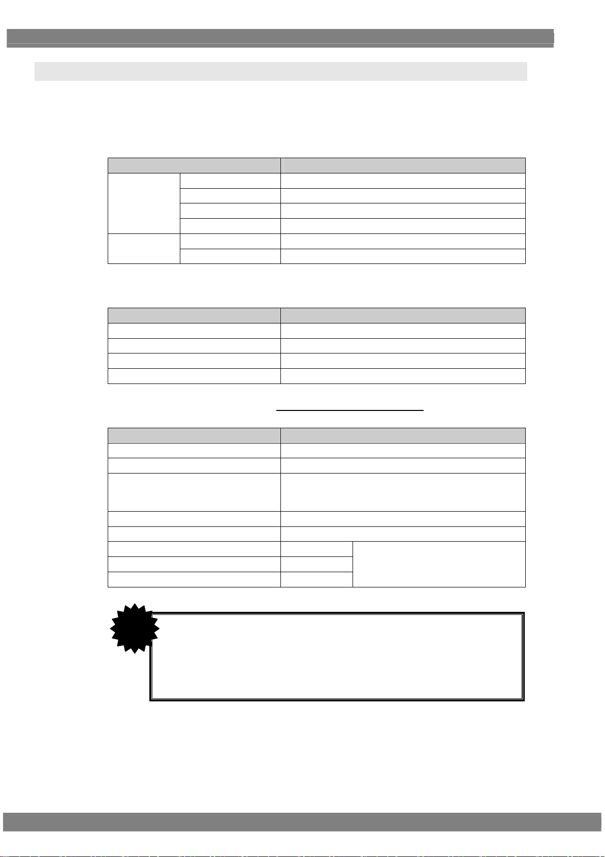
1.3 Data configuration
The data output by the VG-870B/871B is managed by the program data.
The program data consists of the pattern data which is used to set the data relating to the output images
and the timing data which is used to set the data relating to all other output timing data and output
conditions.
The table below gives a breakdown of the data.
Block Description
Timing data
A number of types of program data, optional patterns and user character patterns are contained as
sample data inside the VG-870B/871B.
Number of data
Timing data 1000 (Timing # 1001 to 2000)
Pattern data 1000 (Pattern # 1001 to 2000)
Optional patterns 200 (1 to 200)
User character patterns 16 (F0H to FFH)
The various data can be registered in the internal memory (approx. 100 MB)
VG-870B/871B/873/874 or on CF cards.
Program Name Program name
Timing Timing
Output Output condition
AUDIO Audio output
Pattern Pattern Pattern data
Action Pattern action
of the
Number of data
Program data 1000 (Program # 1 to 1000)
User option patterns 200 (1 to 200)
Images (image data) 200 (1 to 200)
* Number of data depends on the image data size,
memory capacity and card capacity.
User character patterns 16 (E0H to EFH)
Number of characters in program names 20 characters
Number of groups 99 (1 to 99)
Number of group data 98 (1 to 98)
Number of characters in group names 20 characters
CAUTION
When a CF card has been inserted, the data registered on that
card becomes valid, and the data registered in the internal
memory becomes invalid.
In the case of image data, both the data on a CF card and the
data in the internal memory can be made valid. *
* For further details on groups, refer to
“2.4 Groups.”
* For further details, refer to “9.1.11 Image - priority settings.”
2
Page 21
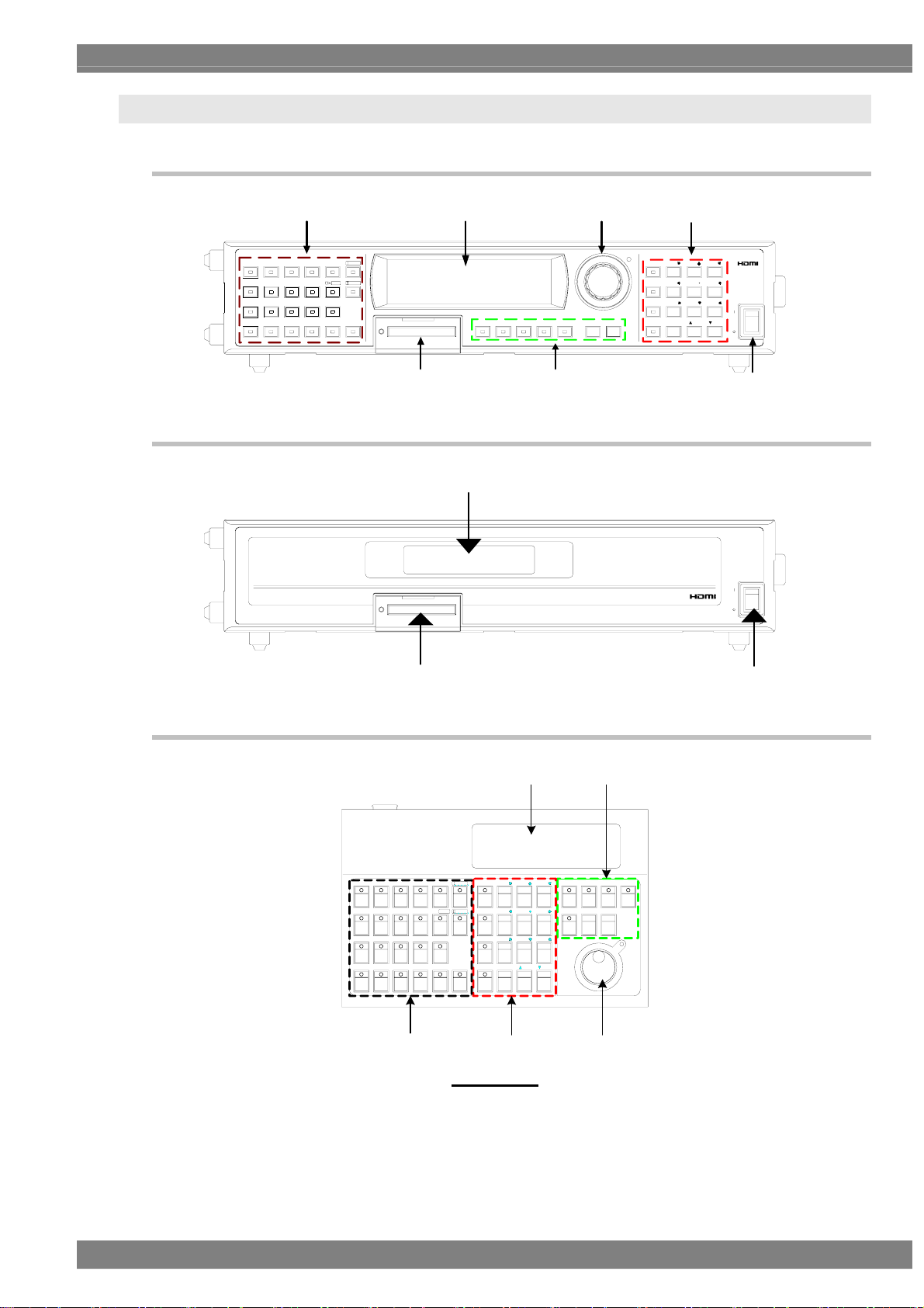
1.4 Panel parts and their functions
1.4.1 VG-870B/873 front panel
Chapter 1 CONCERNING THE VG-870B/871B
GRAYCOLOR SWEEP
RASTER
WIND OW
R/P B/PG/Y
R/P
R
RAMP MONOSCOPE
ASPECT
CHECKER
CURSOR
NAME/LIST
B
IMAGE/OPT
ACTION
HDCP
ABC
MUTE
LEVEL
SYNCB/P INVG/Y
1.4.2 VG-871B/874 front panel
CF CARDDETAIL
CF CARD
(B)(A)
SAMPLECATEGOR Y ESCPATTIM GROUP SET
(B)
(C)
(E)(F)
DIGI TAL VIDEO GENE RATOR VG-871B
(D)
DIGITAL VIDEO GENERATOR VG-870B
7/DMENU
8/E 9/ F
4/A
SHORT CUT
SAVE
6/C5/ B
1
32
0/S TA T USSHIFT
DECINC
AUX
POW ER
POWER
(G)
AUX
POW ER
POWER
1.4.3 RB-1870/RB-1871 panel
REMOTE BOX RB-1870
ASPECTRASTER
CURSOR
WIND OW
NAME/LI ST
RB
G/Y
R/P
RAMP
B/P
(A)
(F)
X
ABC
IMAGE/OPTCHECKER
□
ACTION
LEVEL
INV
RB-1870
DETAILSYNC
(B)
7/D
MENU
SHORT CUT
SAVE 3
SHIFT
0/1INC2DECSTATUS
9/F
8/E
5/B4/A
6/ C
(D) (C)
CATEGORY
(G)
(E)
TIM
PATSAMPLEGRAYCOLOR SWEE P MONOS COP E
ESCGROUP
SET
3
Page 22

SAMPLE
LEVEL
(E )
GRP
789
TIM
123
PAT
SET
0
654
(D)
ⅠⅡ
(A)
RGBINV
INC DEC
RB-1871
Some restrictions apply to operating the RB-1871. The operable items are described below.
Selecting and executing programs
Execution of grouped programs (but group editing is not possible)
ON/OFF operations of R, G, B and INV keys
ON/OFF operations of CUSTOM (I, II) keys (default = I: HDCP, II: MUTE)
Change levels (digital video levels only)
* For further details on the keys, refer to “1.4.4 Names of the keys and their functions.”
4
Page 23
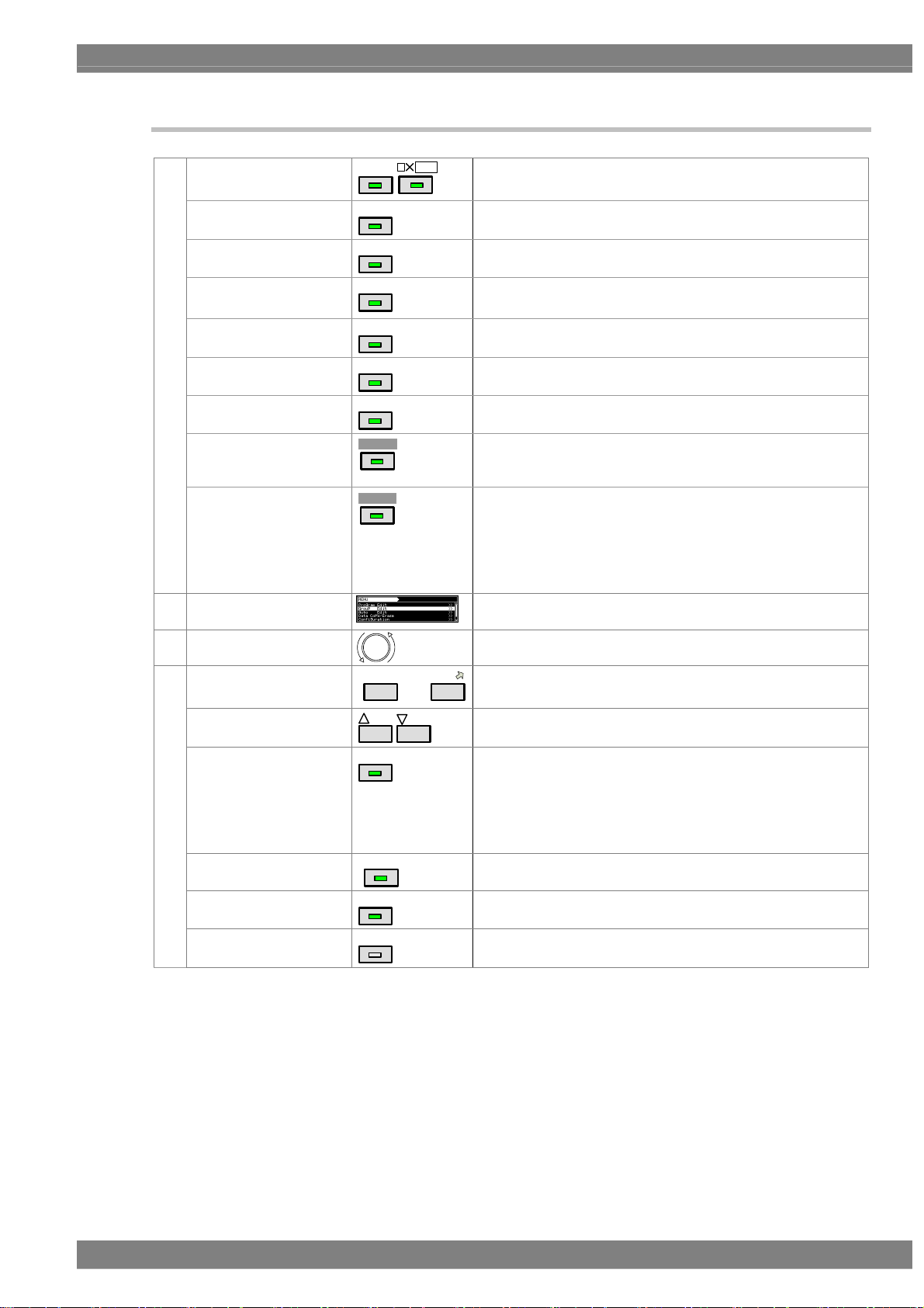
1.4.4 Names of the keys and their functions
INC
ABC
etc.
to
DEC
Used to display and edit the patterns.
etc.
Used when setting the scroll, flicker and other functions.
Used to set the digital video levels, analog video levels and
audio levels.
Used to set R, G and B on or off.
Used to invert the black and white of the video levels.
Used to set the sync on or off.
Used to perform the detailed settings of the pattern data, timing
data, etc.
Used to set HDCP on or off.
(HDCP is a system for protecting content used by HDMI and
DVI.)
Used to set the audio on or off (muted).
* When setting HDMI AV-MUTE
The menu screens are used to set and check the items
displayed on the fluorescent display tube.
This is turned clockwise or counterclockwise to select the
setting items or parameters, change the level settings, etc.
9/F
Used to input numerical values, select the menus, etc.
Used to select the setting items or parameters, change the
level settings, change the program numbers, etc.
Used to display the menu screens.
When it is pressed while a menu screen is already displayed,
the initial screen is restored.
* When the menu key indicator is lighted
Used to move to a user-registered menu screen using minimal
key operations.
Used to save the data which has been set.
Used to input letters of the alphabet with the number keys.
Pattern keys
(A)
Action key
Level key
RGB channel on/off
INV key
SYNC key
Detail key
HDCP key (custom key)
MUTE key (custom key)
(B) Menu operation screens
(C) Rotary switch
Number keys
(D)
INC/DEC
Menu
Short-cut key
Save key
Shift key
COLOR
ACTION
LEV EL
G/Y
INV
SYNC
DETAIL
Ⅰ. HD C P
Ⅱ.MUTE
0/STATUS
MENU
SHOR T CU T
SAVE
SHIFT
Chapter 1 CONCERNING THE VG-870B/871B
This key functions as the HDMI AV-MUTE On/Off setting.
(Refer to “9.1.17 CUSTOM Key1, 2, RB-1871 CUSTOM
Key”.)
It is no longer possible to use any of the other keys.
5
Page 24
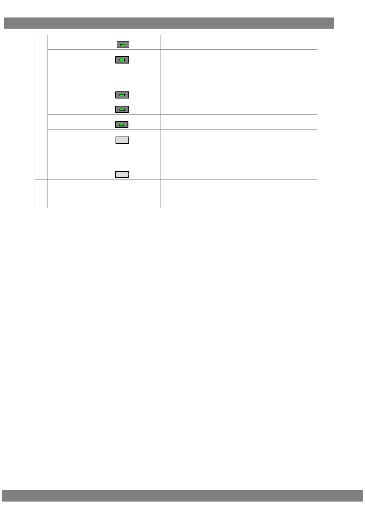
(E)
Category key
CATE GORY
Used to select the internal sample data by category.
Sample key
SAMPLE
Used when the internal sample data is used.
* When the sample key indicator is off
The data stored on CF cards or stored in the internal
memory can be used.
Timing key
Pattern key
Group key
TIM
PAT
GROUP
Used to display changeable lists when only the output timing
data is to be changed.
Used to display changeable lists when only the output pattern
data is to be changed.
Used to display user-registered groups, etc. and create groups.
Escape key
ESC
This key can be used in the following situations
• When canceling parameter selections or numerical value
settings
• When returning the displayed menu screen to the previous
hierarchical level
Set key
(F) CF card slot
SET
Used to enter the setting items and parameters which have
been set.
Used for inserting a CF card or accessing the memory on a CF
card.
(G) Power switch
Used to turn the power of the VG-870B/VG-871B/873/874 on
and off.
6
Page 25
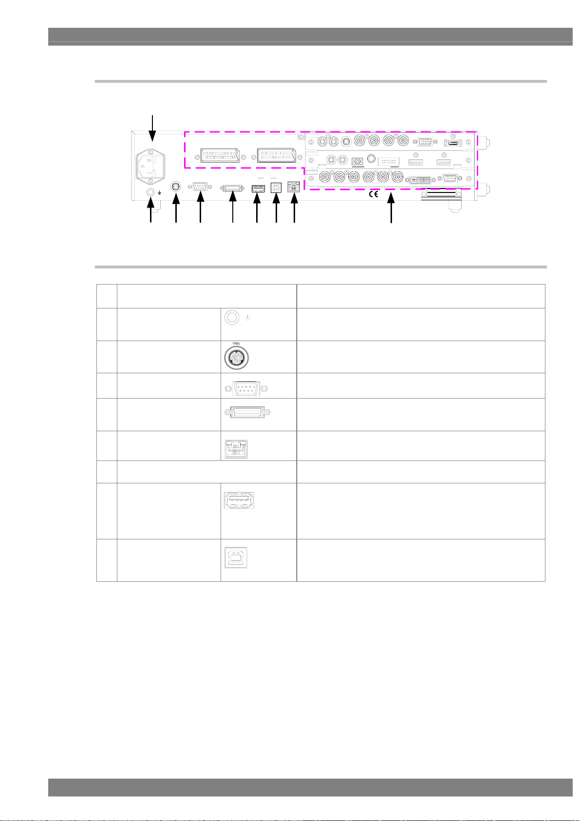
1.4.5 VG-870B/871B/873/874 rear panel
(H)
AC IN (100 -240 V ) T5A
TRIG
SCART 2SCART 1
RS-232 C
REMOTE
USB
2
1
Chapter 1 CONCERNING THE VG-870B/871B
LR
TV
SLOT 2
ANALOG AUDIO OUT
HDMI
SLOT 1
SLOT 0
PC
LAN
LR
ANALOG AUDIO IN
CS VS HS B/P G/Y R /P
PYPCOMPOSITE
BR
COAXIAL
OPT ICAL
DIGITAL AUDIO IN
BR
U.S Patent Nos.4,631 ,603 ;4,577,216 ;
4,819,098 ;4,907,093 ;and 6,516 ,132 .
2
I S
VGA D5Y/C
HDMI 2
HDMI 1
ASTRODESIGN ,Inc.
VGA
MODE L
SER.NO.
MADE IN JAPAN
DVI-I
(O) (P)
1.4.6 Names of connectors and their applications
(H) AC power socket Connect the power cable here.
Any voltage from 100 V to 240 V is supported.
(I) Frame ground
(J) TRIG connector
(K) RS-232C connector
(L) Remote connector
(M) LAN port
(N) Units
(O) USB (1)
(P) USB (2)
LAN
RS-232C
REMO TE
1
2
Connect this frame ground terminal to the frame ground
terminal of the unit which is connected to the
VG-870B/871B/873/874.
This is the trigger input/output connector.
This is used to connect a personal computer using an
RS-232C cable.
This is used to connect the dedicated remote control box
(RB-1870 or RB-1871) to operate the generator by remote
control.
This port is used for connection to a LAN using the Ethernet
cable.
These connectors enable up to three interface units (VM18XX
series) to be installed.
This connector supports a regular USB mouse.
* When the cursor is displayed
Using the USB mouse, the pointer on the monitor can be
moved.
This connector is used to connect the generator with a PC to
enable the VG-870B/871B to be operated using the SP-8870
software, etc. Refer to the instruction manual of the SP-8870
software for further details.
(N)(M)(L)(K)(J)(I)
7
Page 26
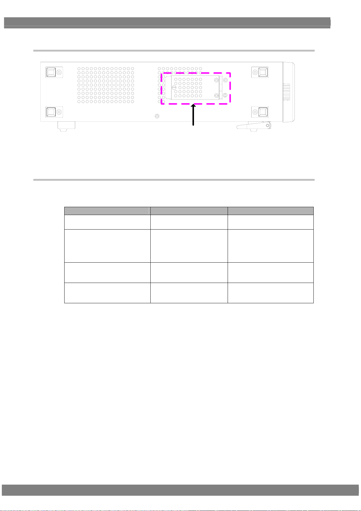
1.4.7 VG-870B/871B/873/874 side panel
※
* Note
Open or close this cover when inserting or removing a CF card for the moving image module.
Do not open the cover while the power is on.
1.4.8 Tools used to operate the VG-870B/871B/873/874
The table below lists the operation tools of this generator and the restrictions on the operation of each of
these tools.
Operation tool Restriction on operation Remarks
VG-870B/873
front panel
RB-1870
RB-1871
SP-8870
These enable all the generator
functions to be operated.
These enable all the generator
functions to be operated.
Programs can be read only.
These enable all the generator
functions to be operated.
The controls can be used only by
the VG-870B/873 main unit.
This remote control box makes it
possible to perform the same
operations as the ones which are
performed on the front panel of
the VG-870B/873.
This is a simplified remote control
box which is intended for use on
production lines.
This software program is intended
for performing operations and
editing using a PC.
8
Page 27
Chapter 1 CONCERNING THE VG-870B/871B
1.5 VG-870B/871B/873/874 video units
The VG-870B/871B/873/874 is constructed to allow video interface units to be installed. Video interface
signals are output from these units. Up to three units can be installed.
* When one or more video units are to be replaced, please contact ASTRODESIGN.
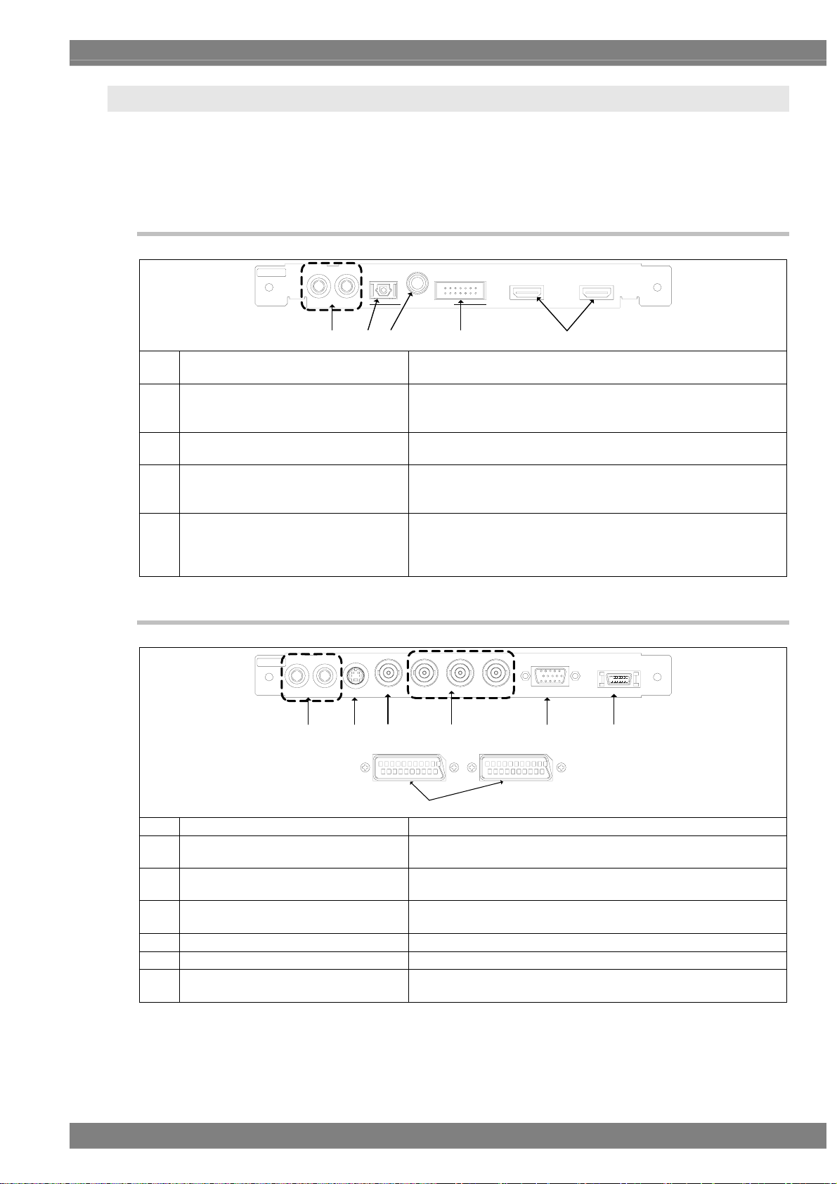
1.5.1 HDMI unit (VM-1817)
OPT ICAL
COAXIAL
DIGITAL AUDIO IN
2
I S
HDMI 2
HDMI
LR
ANALOG AUDIO IN
HDMI 1
(1) HDMI output connectors
(1)(2)(3)(4)(5)
The same images are output simultaneously to two systems.
(HDMI connectors)
(2) I2S digital audio input connector The I2S digital audio signals can be supplied here.
The audio signals which have been input to this connector can be
output as the embedded audio in the HDMI output. (Option)
(3) COAX digital audio input connector
The signals supplied here can be output to the monitor as the
HDMI embedded audio.
(4) TOSLINK digital audio input connector Digital audio signals can be input using an optical connection.
The signals input here can be output to the monitor as the HDMI
embedded audio.
(5) Analog audio input connectors
Analog audio signals (L/R) can be supplied here. (RCA
connectors)
The signals supplied here can be output to the monitor as the
HDMI embedded audio.
1.5.2 TV encoder unit (VM-1812)
ANALOG AUDIO OUT
LR
Y/C
PYPCOMPOSITE
BR
SCART 2 SCART 1
VGA D5
(8)(9)(10)(11)(12)(13)
TV
(14)
(8) D5 output connector Analog component signals can be output here. (D5 connector)
(9) VGA output connector
The analog component signals (RGB) and H/V separate sync
signals can be output here. (Shrink Dsub 15-pin connector)
(10) Analog component output connectors
YPbPr analog component signals can be output here. (BNC
connectors)
(11) Composite output connector
NTSC, PAL or SECAM composite (VBS) signals can be output
here. (BNC connector)
(12) Y/C output connector The Y/C signals can be output here (S connector)
(13) Analog audio output connectors Analog audio signals (L/R) can be output here. (RCA connectors)
(14) SCARToutput connector
NTSC, PAL or SECAM composite (VBS) signals, Y/C signals and
analog component signals (RGBHV) signals can be output here.
9
Page 28
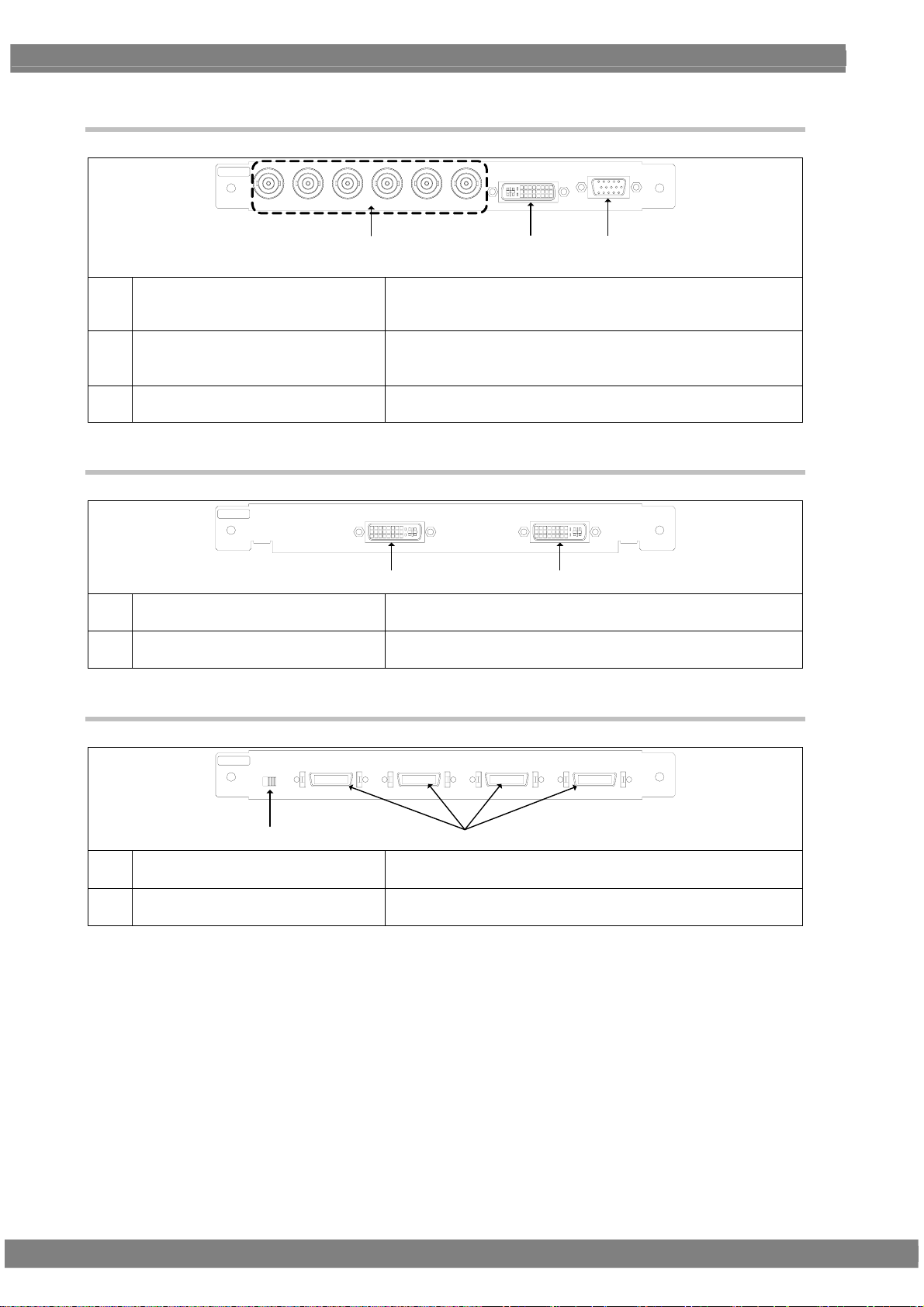
1.5.3 PC analog unit (VM-1811)
PC
CS V S HS B/P G/Y R/P
(15)
DVI-I
BR
VGA
(17)(16)
For details on connectors (7) and (9), refer to the descriptions of the DVI unit and TV encoder unit, respectively.
(15) Analog component output connectors
Either RGB signals or color difference signals (YPbPr/YCpCr) can
be selected and output here.
H/V separate sync and CS (composite sync) can be output.
(16) DVI-I output connector Digital or analog signals can be output from this connector.
(DVI-I connector)
HDCP is supported. (Dual-Link is not supported.)
(17) VGA output connector
Analog component signals (RGBHV) can be output as separate
H/V sync signals here. (Shrink Dsub 15-pin connector)
1.5.4 DVI unit (VM-1814)
DVI
(6) DVI-D output connector Only digital signals can be output here. (DVI-D connector)
(7) DVI-D output connector Only Digital signals can be output here. (DVI-D connector)
DVI-D 2 DVI-D 1
(6)(7)
Dual-Link is supported. (HDCP is not supported.)
HDCP is supported. (Dual-Link is not supported.)
1.5.5 LVDS unit (VM-1815)
LVD S
DDC
5V
(18) LVDS output connectors The signals of four 10-bit systems can be output here.
(19) (DDC power supply selector switch) This switch is not normally used.
LVD S 4 LVDS 3 LV D S 2 LV DS 1
3.3V
(18)(19)
DISM or OpenLDI can be selected.
It can select the supply voltage when DDC is used.
10
Page 29
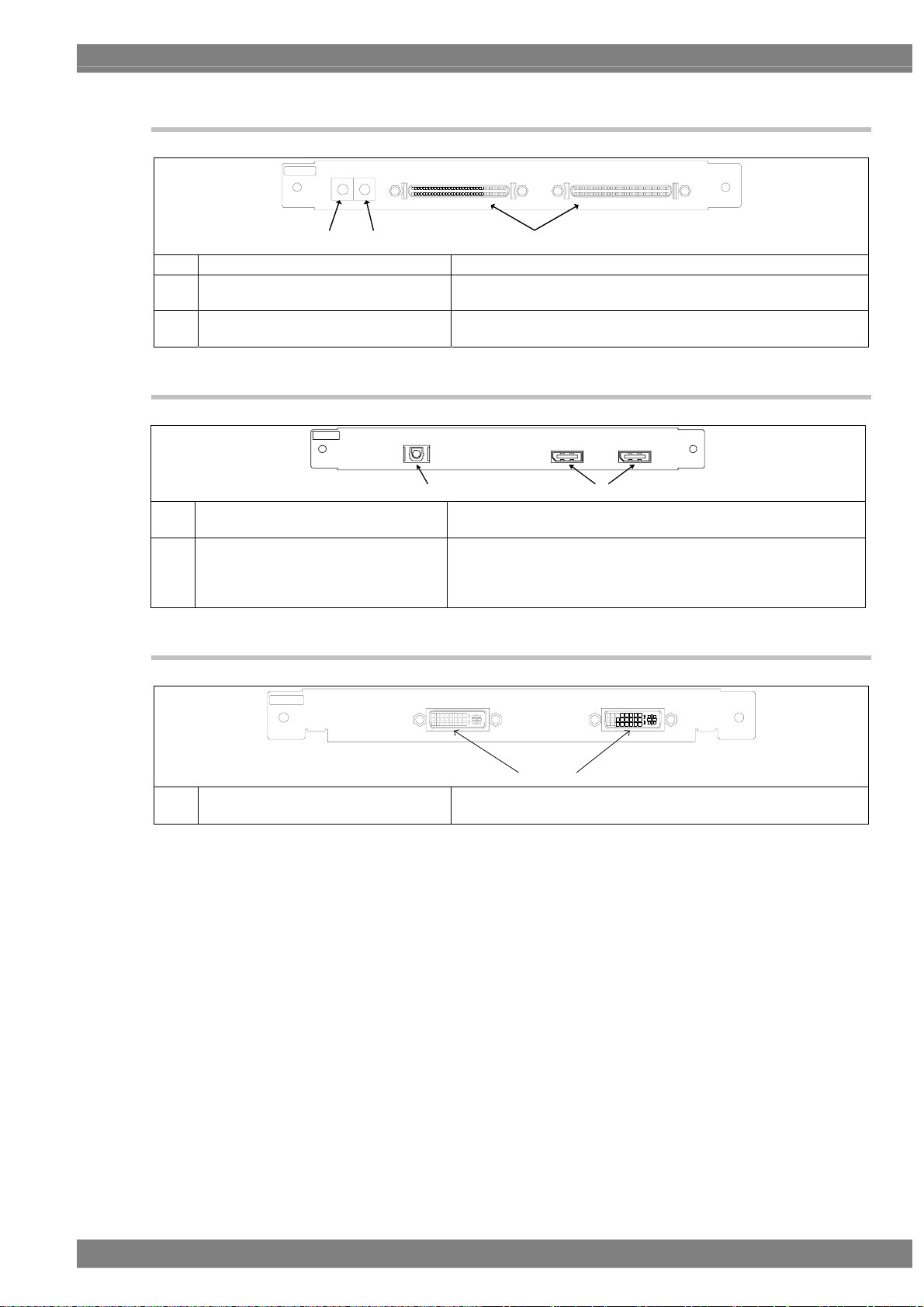
1.5.6 Parallel unit (VM-1816)
PA R ALLEL
SIGNAL POWER
Chapter 1 CONCERNING THE VG-870B/871B
PA RA LLEL 2 PA RA LLEL 1
(20)(22) (21)
(20) Parallel output connectors The signals of two 8-bit systems can be output here.
(21) Supply voltage setting
This enables the supply voltage (1.8 V, 2.5 V, 3.3 V or 5 V) to be
selected.
(22) Signal level setting
This enables the signal level (1.8 V, 2.5 V, 3.3 V or 5 V) to be
selected.
1.5.7 DisplayPort unit (VM-1820 .. discontinued)
DP
AUDIO IN
OPTICAL DisplayPort2
DisplayPort1
(24) (23)
(23) DisplayPort output
Two systems of split drawing signals can be simultaneously
output here.
(24) TOSLINK digital audio input
This connector enables digital audio data to be input using an
optical connection.
Digital audio data can be output to the monitor as the embedded
audio data of the DisplayPort output.
1.5.8 4K2K iTMDS unit (VM-1824)
iTMDS
DVI-D 2 DVI-D 1
(25)
(25) iTMDS(DVI) output connectors Only Digital signals can be output here. (iTMDS connector)
Dual-Link is supported. (HDCP is not supported.)
11
Page 30

1.5.9 4K2K iTMDS Quad unit (VM-1824-A)
iTMDS Quad
DVI-D 4 DVI-D 3
DVI-D 2 DVI-D 1
(26)
(25) iTMDS (DVI) output connectors Only Digital signals can be output here. (iTMDS connector)
Single link is supported.
1.5.10 V-by-One HS unit (VM-1825)
R
V-by-One HS
(27) V-by-One HS output connectors
1.5.11 SDI unit (VM-1821)
SDI
CH2 CH1
(27)
These connectors support up to 4 lanes with one channel (and 8
lanes with two channels).
SDI4 SDI3 SD I2 SDI1
(28) SDI output connectors
(28)
These connectors support four SD, HD or 3G signals or two Dual
Link signals.
12
Page 31

1.5.12 HDMI (3D, ARC) unit (VM-1822)
HDMI
COAXCOAX OUT
AUDIO IN
Chapter 1 CONCERNING THE VG-870B/871B
2
I S
HDMI
OUT 2
HDMI
OUT 1
(29)(30)(31)(32)
(29) HDMI output connectors
The same images and sound can be output simultaneously from
these two connectors. (HDMI connectors)
(30) I2S digital audio input connector The I2S digital audio signals can be supplied here.
The audio signals which have been input to this connector can be
output as the embedded audio in the HDMI output. (Option)
(31) COAX digital audio input connector
The signals supplied here can be output to the monitor as the
HDMI embedded audio.
(32) COAX digital audio output connector
(ARC only)
The sound input by the ARC function
connector as it is.
1.5.13 HDMI 300MHz Unit (VM-1823)
LAN
HDMI
OUT 2
HDMI
OUT 1
(33)(35)(36)(37) (34)
(33) HDMI Output
(34) LAN
I2S digital audio input
(35)
connector
COAX digital audio input
(36)
connector
HDMI
COAXCO AX OU T
AUDIO IN
2
I S
The same images and sound can be output simultaneously from
these two connectors. (HDMI connectors)
When using HEC function, the Ethernet that is input from VG is
thoroughly output.
The I2S digital audio signals can be supplied here.
The audio signals which have been input to this connector can be
output as the embedded audio in the HDMI output. (Option)
The signals supplied here can be output to the monitor as the HDMI
embedded audio.
of HDMI is output from this
COAX digital audio output
(37)
connector (ARC only)
1.5.14 DisplayPort Unit (VM-1820A)
DP
(38) DisplayPort Output
COAX digital audio
(39)
input
Outputs 2 channels simultaneously and split-drawing is available.
This connector enables digital audio data to be input using a coaxial
connection.
Digital audio data can be output to the monitor as the embedded audio data
of the DisplayPort output.
The sound input by the ARC function of HDMI is output from this
connector as it is.
DISPLAY PORT 2
(38) (39)
DISPL AYPO RT 1
COAX IN
13
Page 32

1.5.15 DisplayPort, eDP Unit (VM-1826)
DP /eDP
eDP CONTRO L+POWE R OUTeDP E XT POW ER IN
DISPLAY PORT 2
DISPL AYPO RT 1
COAX IN
(40) (41)(42)(43)
(40) DisplayPort Output Outputs 2 channels simultaneously and split-drawing is available.
COAX digital audio
(41)
input
Power, control signal
(42)
output
(43) External power input External powers (2 lines) are input here.
CAUTION
Do not attempt to remove the interface units from
the main unit due to the risk of damage.
When units are to be added or replaced, please
contact ASTRODESIGN.
This connector enables digital audio data to be input using a coaxial
connection.
Digital audio data can be output to the monitor as the embedded audio data
of the DisplayPort output.
Power (4 lines) and control signal (8 lines) are output.
14
Page 33

V
A
OPERATION PROCEDURES
2
2
2.1 Flow of basic operations
2.1.1 Settings required for displays
The timing data and pattern data must be set in order for the test patterns to be displayed from the
generator. The following items are set for these data.
In the case of this generator, the timing data and pattern data are collectively referred to as the
“program data.”
Program data
Timing data
ideo timing data settings
- Horizontal timing
- Vertical timing
Output settings
- On or off for each interface
- Settings inherent to interfaces
DVI-D 1
Audio output settings
- Sound source, level
- Frequency
- On or off of channels
V-SYNC
Video
H-SYN C
PYP
BR
Pattern data
Patter data settings
- Type, size, level and other settings
ction settings
- Scroll
- Flicker
- Level sweep
15
Page 34

2.1.2 Selecting the timing data
There are two ways to select the timing data.
1) Input the timing data numbers directly.
2) Select the timing data from the categories.
1) Input the timing data numbers directly.
(1)
Input the timing data number (1001 to 1999)
using
0/STATUS
(
SAMPLE
to
TIM
number keys
9/F
).
2) Select the timing data from the categories.
The timing data of the internal sample data is classified by category such as EIA or VESA (PC). Select the
desired timing data from the category which contains it.
(1)
CATE GORY
SAMPLE
TIM
(2)
Select the category using
DEC
, and then press
SET
.
(3)
Select the timing data using
DEC
, and then press
SET
.
or
or
INC
INC
Video timing data output
V-SYNC
Video
H-SYNC
The display patterns are not changed.
Video timing data output
V-SYNC
Video
H-SYNC
The display patterns are not changed.
16
Page 35

2.1.3 Selecting the pattern data
There are four ways to select the pattern data.
1) Input the pattern data numbers directly.
2) Select the pattern data from the categories.
3) Select the pattern data using the pattern keys.
4) Select the patterns for each program data.
1) Inputting the pattern data numbers directly
Chapter 2 OPERATION PROCEDURES
(1)
Input the pattern data number (1001 to 1999)
using
0/STATUS
(
SAMPLE
to
PAT
number keys
9/F
).
2) Selecting the pattern data from the categories
(1)
CATE GORY
SAMPLE
PAT
(2)
Select the category using
DEC
, and then press
or
SET
.
(3)
Select the pattern using
SET
and then press
.
or
3) Selecting the pattern data using the pattern keys
INC
INC
The corresponding pattern is displayed.
etc.
The pattern category is displayed.
DEC
The pattern is displayed.
,
etc.
(1)
Select the key corresponding to the pattern,
COLOR
such as
(2)
When setting details for the pattern or changing
or
ABC
, to be displayed.
the pattern type.
DETAIL
Press
.
(3)
Select the pattern using or
SET
and then press
.
Select the pattern directly using the number keys
0/STATUS
(
Press
9/F
to
4/A
).
to select .
INC
The pattern of the selected type is displayed.
Lighted:
COLOR
selected; off:
COLOR
The pattern selection screen is displayed.
DEC
The selected pattern is displayed.
,
deselected.
17
Page 36

4) Selecting the patterns for each program data
(1)
Select Program Edit using
DEC
INC
or
, and then press
MENU
SET
.
(2)
Select Pattern (PAT) using
DEC
, and then press
SET
.
INC
or
(3)
Select Pattern/RGB/INV Select using
SET
or
INC
DEC
, and then press
.
(4)
Select the item using
and then press
Selected or deselected is displayed.
INC
or
SET
.
The selected pattern is indicated by a check mark .
Color Bar
,
Gray Scale
Ramp
Sweep
Check this to select the color bar pattern.
Check this to select the gray scale pattern.
Check this to select the ramp pattern.
Check this to select the sweep (sine wave)
pattern.
Monoscope
Check this to select the monoscope
DEC
pattern.
Raster
Aspect
Check this to select the raster pattern.
Check this to select the pattern for
checking the aspect ratio.
Checker
Check this to select the checkerboard
pattern.
Image/OPT
Check this to select the bitmap image, an
optional pattern, or a moving image.
Character
Cross Hatch
Dot
Check this to select the character pattern.
Check this to select the crosshatch pattern.
Check this to select the dot pattern.
Check this to select the frame pattern.
Check this to select the cross pattern.
Check this to select the center marker
pattern.
Circle
Burst
Check this to select the circle pattern.
Check this to select burst (continuous
black and white).
Window
Cursor
Name/List
R/Pr
Check this to select the window pattern.
Check this to select the cursor pattern.
Check this to select the name/list function.
Check this to set the pattern R (red) or Pr
output on or off.
Normally, this is kept checked.
G/Y
Check this to set the pattern G (green) or Y
(luminance) output on or off. Normally, this
is kept checked.
B/Pb
Check this to set the pattern B (blue) or Pb
output on or off.
Normally, this is kept checked.
INV
Check this invert the black and white of the
video level.
18
Page 37

2.1.4 Selecting the actions
There are two ways to select actions.
1) Select the action using the action key.
2) Select and set the action for each program data.
1) Selecting the action using the action key
(1)
Press the
ACTION
key.
Chapter 2 OPERATION PROCEDURES
The action selection screen is displayed.
(2)
Select the action using
and then press
(3)
Select the action using
and then press
SET
SET
DEC
INC
or
The selected action is indicated by a check mark .
,
.
To select the window action, the window pattern must be
displayed first.
GC-SCROL
G-SCROLL
C-SCROLL
W-SCROLL
W-FLICKR
W-LEVEL
W-L.SEQ
Check this to scroll the pattern.
Check this to scroll the pattern.
Check this to scroll the pattern.
Check this to scroll the window.
Check this to flicker the window.
Check this to change the window level.
Check this to execute the window level
sequence.
M-BLUR
S-SCROLL
DEC
INC
or
,
.
Check this to execute motion blur.
Check this to scroll the subtitle pattern.
On this screen, the scroll direction and number of steps are
set when the GC-SCROL, G-SCROLL or C-SCROLL
action has been checked.
←, →, ↑, ↓
Select these to scroll in the directions of
the arrows.
||
RESET
Select this to stop the scrolling temporarily.
Select this to return the pattern to its
original position.
(It is displayed only while scrolling is
stopped temporarily.)
STEP+1
Select this to increment the scroll step by
1.
STEP-1
Select this to decrement the scroll step by
1.
EDIT
Select this to perform the detailed scroll
settings.
19
Page 38

DEC
or
INC
,
(4)
Select the action using
and then press
SET
.
On this screen, the scroll direction and number of steps are
set when the W-SCROLL action has been checked.
←, →, ↑, ↓
Select these to scroll in the directions of
the arrows.
||
RESET
Select this to stop the scrolling temporarily.
Select this to return the pattern to its
original position.
(It is displayed only while scrolling is
stopped temporarily.)
STEP+1
Select this to increment the scroll step by
1.
STEP-1
Select this to decrement the scroll step by
1.
EDIT
Select this to perform the detailed scroll
settings.
DEC
or
INC
,
(5)
Select the action using
and then press
SET
.
On this screen, the level increment/decrement and
direction as well as the number of steps are set when the
W-LEVEL action has been checked.
UP
DOWN
STOP
Select this to increment the level.
Select this to decrement the level.
Select this to temporarily stop the level
change.
STEP+1
Select this to increment the level change
step by 1.
STEP-1
Select this to decrement the level change
step by 1.
EDIT
Select this to perform the detailed level
settings.
DEC
or
INC
,
(6)
Select the action using
and then press
SET
.
On this screen, the scroll direction and number of steps are
set when the S-SCROLL action has been checked.
←, →, ↑, ↓
Select these to scroll in the directions of
the arrows.
||
RESET
Select this to stop the scrolling temporarily.
Select this to return the pattern to its
original position.
(It is displayed only while scrolling is
stopped temporarily.)
STEP+1
Select this to increment the scroll step by
1.
STEP-1
Select this to decrement the scroll step by
1.
EDIT
Select this to perform the detailed scroll
settings.
20
Page 39

2) Select and set the action for each program data.
(1)
MENU
Select Program Edit using
SET
or
INC
DEC
, and then press
(2)
Select Action (PAT) using
DEC
, and then press
(3)
Select the item using
and then press
SET
SET
.
or
.
INC
or
Chapter 2 OPERATION PROCEDURES
.
INC
DEC
One of the following actions is selected, and the detailed
settings are performed.
,
For details on the setting procedure, refer to “ACTION
SETTINGS.”
• Graphic Plane
• Character Plane
• Window
• Subtitle
• Motion Blur
• 0.25 / 0.125 dot Scroll
• Lip Sync
• Black Insertion
21
Page 40

2.2 Saving the program data
Upon completion of program editing, save the data.
If the power is turned off without saving the data, the status before the changes were made will be restored.
SAVE
(1)
DEC
(2)
Select the item using
and then press
(3)
Select
DEC
, and then press
CAUTION
SET
.
using or
SET
If a CF card has been inserted, the data registered on the card
will be enabled and the data registered in the internal memory
will be disabled.
For the image data, it is possible to enable both the data
registered on the CF card and the data in the internal memory.
*
INC
or
INC
.
No.
,
Media
Program
Name
Pattern Name
The program data is saved.
The program number is set here.
(0001 to 1000)
The internal memory or CF card is selected
here.
Any name (containing up to 20 characters)
can be allocated as the program name.
Any name (containing up to 20 characters)
can be allocated as the pattern name.
* For further details, refer to “9.1.11 Image - priority settings.”
22
Page 41

Chapter 2 OPERATION PROCEDURES
2.3 Setting the names
When timing or pattern data is edited and the edited data is to be saved, the name used for the program can be
changed.
(1)
Select Name using or
SET
then press
To decide on the positions where the
(2)
.
character changes are to be made:
INC
(when moving to the left)
DEC
(when moving to the right)
To delete all the characters:
R/Pr
To delete one character:
G/Y
To change character insert/overwrite:
B/Pb
Use this to switch between inserting and
overwriting the characters.
INC
DEC
, and
The position where the character of the name is to be
input changes.
All the characters already input for the name are
cleared.
The character at the cursor position is deleted.
Insert is switched to overwrite or vice versa.
To input characters:
Select the characters using , and enter
SET
them using
(3) To enter the program name:
Select OK using
.
The characters are input.
The name is changed.
SET
.
23
Page 42

2.4 Groups
Registering programs as “groups” is useful when specific programs are to be combined and used
repeatedly.
Examples include times on a TV set inspection process when specific timing and pattern data are
combined for repeated use.
It is possible to set not only the timing and pattern data execution sequence but the execution time of
each program as well.
Group
Program-6
Time
Program-15
Time
Program-10
Time
Up to 98 programs can be registered in a group. Up to 99 groups can be registered.
2.4.1 Executing groups
The combinations of programs and patterns which are used with a high frequency and which have been registered
by the user can be executed.
GROUP
(1)
DEC
or
or
INC
INC
,
Only the programs registered as groups can be selected.
DEC
The programs in the group are executed.
or
DEC
is used, the programs are
,
INC
When
executed in ascending or descending order without
SET
pressing
.
(2)
Select the groups using
and then press
(3)
Select the groups using
and then press
SET
.
SET
.
24
Page 43

Chapter 2 OPERATION PROCEDURES
2.4.2 Setting and saving groups
The combinations of programs and patterns which are used with a high frequency can be saved.
MENU
(1)
(2)
Select Group Edit using
DEC
, and then press
(3)
Select the items using
SET
and then press
(4)
Select the numbers (01 to 98) of the TIM or PAT
.
or
SET
.
INC
or
SET
programs and AutoInterval using
DEC
INC
or
, and then press
The programs set in the group are executed in
sequence from 01 up to 98.
• If 0 is set for both TIM and PAT
• If 0 is set for Program
In both of the above cases, 0 is recognized as
the end of the group.
(5) This completes the setting operations.
The group data is now saved.
SAVE
(6)
Select the items using
and then press
SET
.
INC
or
(7)
Select
DEC
, and then press
using or
SET
.
If previous data exists, a display appears prompting the
user to confirm whether it is acceptable for the existing
data to be overwritten.
INC
SET
INC
DEC
No.
,
Name
The number of the desired group is set
here. (01 to 99)
Any name (consisting of up to 20
characters) can be allocated as the group
name.
Edit Mode
TIM/PAT: The timing data and pattern data
are set separately.
Program: The number of the program is
designated here.
Program
Depending on the Edit Mode setting, the
display screen in (4) below will differ.
When TIM/PAT is selected as the Edit Mode setting
.
When Program is selected as the Edit Mode setting
TIM/PAT
The program numbers are set in this column.
TIM The timing data numbers are listed here.
PAT The pattern data numbers are listed here.
Auto Interval
The execution times during Auto Display
are set here (0 to 999 seconds).
DEC
,
No.
Media
The number of the group is set here. (01 to 99)
Internal: The group data is saved in the
internal memory.
CF Card: The group data is saved on an
external CF card.
Name
Any name (consisting of up to 20
characters) can be allocated.
This completes the saving of the group data.
25
Page 44

2.5 Automatic execution
The data in the selected groups and program numbers can be automatically output in accordance with the delay time
which has been set.
MENU
(1)
(2)
Select Auto Edit using
and then press
Selecting the Mode setting
(3)
SET
.
or
Select Program or Group using or
0/STATUS
1
.
(4)
Select Setting using
SET
and then press
or
.
INC
INC
DEC
DEC
,
<When Program has been selected as the Mode
setting>
,
Interval:
The time during which each pattern is to be displayed is set
here from 0 to 999 seconds.
Program (Start-Stop):
The start and end points of programs to be repeated are set
here.
The start and end point settings can be designated in three
stages.
Automatic execution is performed in the following
sequence: Start point 1 → end point 1 → start point 2 →
end point 2 → start point 3 → end point 3.
<When Group has been selected as the Mode setting>
26
(5) For automatic execution, select EXECUTE using
DEC
INC
or
, and then press
To cancel automatic execution at any time, press
ESC
.
Group No.:
The number of the group to be executed automatically is
set here.
Interval
The time during which each pattern is to be displayed is set
here from 0 to 999 seconds.
When 0 is set, execution accords with the group data
setting. If the interval is not set in the group data, 0 seconds
will be set.
SET
.
Page 45

(6)
SAVE
Select Auto Data SAVE using
DEC
INC
or
.
(7) Select the save destination (*) at Media using
DEC
INC
or
, and then press
Chapter 2 OPERATION PROCEDURES
SET
.
Select EXECUTE using or
INC
DEC
SET
, and then press
* Internal: The data is saved on the internal memory.
CF-card: The data is saved on the CF card.
.
27
Page 46

g
r
(
y
g
g
g
2.6 Displays appearing on the VG-871B / 874 fluorescent
display tube
The following information appears on the VG-871B/874 fluorescent display tube.
When selecting and executing programs
Standard display
SAMPLE, TIM and PAT key statuses
Pattern drawing bit length, horizontal sync frequency, vertical sync frequenc
Group execution
When selecting groups
ON: S T P OFF: +
Number of pro
Group number
Pro
ram in group
ram numbe
Pro
Name of program or pattern (max. 16 characters)
ram name (max. 16 characters)
With TIM at OFF)
HDCP ON/OFF ON: ⇔z flashing
OFF: z no flashin
Group number
When adjusting the digital video levels
Group name
Digital video level
28
Page 47

A
TIMING DATA SETTINGS
3
3
3.1 Horizontal timing data editing
3.1.1 Horizontal timing data
When making changes with the horizontal timing data, the parameters which can be set and the names
of the parameters are indicated below.
DispBackpSyn c
Period
HDstart HDwidt h
3.1.2 Restrictions on the horizontal timing parameters
The table below shows the restrictions on the parameters which can be changed with the horizontal
timing data.
Setting item
Dot Clock
Period
Disp
Backp, Sync
HDstart, HDwidth
* When a parameter is fixed, it is accompanied by an asterisk (*). Even when values other than ones
for parameters with an asterisk have been changed, the values of the parameters with the asterisks
remain fixed.
Example: When us setting has been fixed using SHIFT+2 for Period
CAUTION
Setting range Parameter fixing function
0.100 to 1360.000 MHz
* Depending on the number of bits which
are output, the dot clock frequency is
subject to some restrictions. For details,
refer to “11.1.1 Common specifications.”
Time display: 0.00 to 999.999 µs
Dot display: 128 to 8192 dots
Time display: 0.00 to 999.999 µs
Dot display: 48 to 4096 dot
Time display: 0.00 to 999.999 µs
Dot display: 0 to 8192 dot
Time display: 0.00 to 999.999 µs
Dot display: 0 to 8190 dot
n asterisk is displayed here when the value is fixed.
When items are set in microseconds (µs), restrictions
apply to these settings depending on the dot clock
frequency and other timing data used for drawing.
µs setting fixed using SHIFT+2
dot setting fixed using SHIFT+3
µs setting fixed using SHIFT+0
dot setting fixed using SHIFT+1
29
Page 48

The values for the blanking and frontp items are calculated automatically on the basis of the data
presented above.
Item
Blanking Blanking = Period - Disp
Calculation formula Setting range
Time display: 0.00 to 999.999 µs
Dot display: 40 to 8192 dots
Frontp Frontp = Period - Disp - Sync - Backp
Time display: 0.00 to 999.999 µs
Dot display: 0 to 8192 dots
3.1.3 Horizontal timing data setting procedure
Described below is the procedure used to set the parameters which can be changed with the horizontal timing data
(1)
Select Program Edit using
DEC
INC
or
, and then press
(2)
Select Timing (TIM) using
DEC
, and then press
(3)
Select H-Timing using or
SET
and then press
<Setting the parameters>
Select the items using or
SET
and then press
Alternatively:
Select the parameter using the number keys
0/STATUS
(
to
9/F
), and then press
MENU
SET
.
INC
or
SET
.
DEC
INC
,
.
Set the H-Timing parameters.
DEC
INC
Input Mode
,
Select the input setting for the H-Timing
parameters to µs: time [microseconds] or
dot: number of dots [dots].
.
Dot Clock The dot clock frequency (MHz) is set here.
Repetition The number of repetitions is set here.
The pixel configuration depends on the
SET
.
Period
number which is set in Repetition.
When 2 is set for Repetition and 1440 for
Disp, the number of pixels will be 720.
The total number of pixels in the horizontal
direction is set here.
<When µs: time (microseconds) has
been selected as the Input Mode
setting>
It is possible to establish settings using
both µs and dot parameters.
Disp
Set the Disp width in the horizontal
direction here.
<When µs: time (microseconds) has
been selected as the Input Mode
setting>
It is possible to establish settings using
both µs and dot parameters.
Sync
Set the Sync width in the horizontal
direction here.
BackP
Set the BackP width in the horizontal
direction here.
HDStart
HDWidth
These parameters can be set only when
the parallel unit has been installed.
30
Page 49

3.2 Vertical timing data editing
The vertical timing setting locations and names of the settings are indicated below.
3.2.1 Vertical timing data
[For progressive scanning]
Serration
EQP-Fp EQP-Bp
Chapter 3 TIMING DATA SETTINGS
Sync
VDstart VDline
[For interlaced scanning]
Backp
Disp
Total
3.2.2 Restrictions on the vertical timing parameters
The table below shows the restrictions on the parameters which can be changed with the vertical timing
data.
<For progressive scanning>
Setting item
Tot al
Disp
Sync
Backp
VDstart , VDline
Setting range Parameter fixing function
Time display: 0.00 to 999.999 ms
Dot display: 8 to 8192 H
Time display: 0.00 to 999.999 ms
Dot display: 2 to 4096 H
Time display: 0.00 to 999.999 ms
Dot display: 1 to 99 H
Time display: 0.00 to 999.999 ms
Dot display: 1 to 8192 H
Time display: 0.00 to 999.999 ms
Dot display: 0 to 8190 H
ms setting fixed using SHIFT+2
H setting fixed using SHIFT+3
ms setting fixed using SHIFT+0
H setting fixed using SHIFT+1
31
Page 50

A
<For interlaced scanning>
Setting item
Field-1 Total1
Disp1
Sync1
Backp1
VDstart1
VDline1
Field-2 Total2
Disp2
Sync2
Backp2
VDstart2
VDline2
Setting range Parameter fixing function
Time display: 0.00 to 999.999 ms
Dot display: 4.0 to 4096.0 H
(in 0.5H increments)
Time display: 0.00 to 999.999 ms
Dot display: 1 to 2048 H
Time display: 0.00 to 999.999 ms
Dot display: 1.0 to 99.0 H
(in 0.5H increments)
Time display: 0.00 to 999.999 ms
Dot display: 0.0 to 4096.0 H
(in 0.5H increments)
Time display: 0.00 to 999.999 ms
Dot display: 0.0 to 4095.0 H
(in 0.5H increments)
Time display: 0.00 to 999.999 ms
Dot display: 0.0 to 4095.0 H
(in 0.5H increments)
Fixed to ms setting using SHIFT+2
Fixed to H setting using SHIFT+3
Fixed to ms setting using SHIFT+0
Fixed to H setting using SHIFT+1
Same as Field-1 Same as Field-1
* When a parameter is fixed, it is accompanied by an asterisk (*). Even when values other than ones
for parameters with an asterisk have been changed, the values of the parameters with the asterisks
remain fixed.
Example: When an ms setting has been fixed using SHIFT+2 for Total
CAUTION
When the time display (ms) is set for the items,
restrictions apply to these settings depending on the
H-period and other timing data used for drawing.
n asterisk is displayed here when the value is fixed.
32
Page 51

Chapter 3 TIMING DATA SETTINGS
The values for the blanking and frontp items are calculated automatically on the basis of the data
presented above.
<For progressive scanning>
Item
Blanking
Frontp
<For interlaced scanning>
Item
Frontp1
(Frontp2)
Blanking1
(Blanking2)
Calculation formula Setting range
Blanking = Total - Disp Time display: 0.00 to 999.999 ms
Dot display: 2 to 8192 H
Frontp = Total - Disp - Sync - Backp Time display: 0.00 to 999.999 ms
Dot display: 0 to 8192 H
Calculation formula Setting range
Frontp1 = Total2 - Disp2 - Sync2 - Backp2
(Frontp2 = Total1 - Disp1 - Sync1 - Backp1)
Blanking1 = Frontp1 + Sync1 + Backp1
(Blanking2 = Frontp2 + Sync2 + Backp2)
Time display: 0.00 to 999.999 ms
Dot display: 0.0 to 4096.0 H
Time display: 0.00 to 999.999 ms
Dot display: 2.0 to 4096.0 H
33
Page 52

3.2.3 Vertical timing data setting procedure
Described below is the procedure used to set the parameters which can be changed with the vertical timing data.
(1)
Select Program Edit using
DEC
INC
or
, and then press
(2)
Select Timing (TIM) using
DEC
, and then press
(3)
Select V-Timi ng using or
SET
and then press
Select the items using
SET
and then press
Select the parameter using the number keys
0/STATUS
(
to
9/F
), and then press
* In the case of interlaced scanning outputs,
Total, Disp, Sync and BackP are set for both
Field1 and Field2.
MENU
SET
.
INC
or
SET
.
DEC
INC
,
.
DEC
INC
or
Set the V-Timing parameters.
Input Mode
,
Select the input setting for the V-Timing
parameters to ms: time [milliseconds] or H:
.
SET
Scan Refer to “3.2.4 Concerning the scanning
TV Mode
.
number of lines [H].
modes.”
As a general rule, do not change this
setting. For further details, refer to “3.2.5
Concerning the TV modes.”
To ta l
The Total number in the vertical direction is
set here.
Disp
The Disp width in the vertical direction is
set here.
Sync
The Sync width in the vertical direction is
set here.
BackP
The BackP width in the vertical direction is
set here.
Serration/EQP
Refer to “3.2.6 Concerning Serration and
EQP.”
VD
Set VDStart and VDline here. This
parameter can be set only when the
parallel board has been installed.
34
Page 53

3.2.4 Concerning the scanning modes
The table below lists the V-Timing scan settings as well as the operations for the scanning methods
supported by the settings, imaging methods and action settings.
Chapter 3 TIMING DATA SETTINGS
Scan mode
Progressive
Interlace
Prog.Segmented
Frame
Interlace (Sync)
System Pixel imaging Scroll and other actions
Progressive scanning
Interlaced scanning
Interlaced scanning
Interlaced scanning
Different pixels are drawn on
each line.
Different pixels are drawn in
the first field and second field.
Different pixels are drawn in
the first field and second field.
The same image is
repeatedly drawn
field and second field.
in the first
Operation is performed
for each frame.
Operation is performed
for each field.
Operation is performed
for each frame (2 fields).
Operation is performed
for each field.
3.2.5 Concerning the TV modes
This parameter indicates the output of the TV standard signals (NTSC, NTSC-M, NTSC-443, PAL,
PAL-M, PAL-60, PAL-N, PAL-Nc, SECAM, HDTV1080 or HDTV 720).
Even when this parameter is changed, the timing data and other data will not be edited. For this reason,
when it is changed, it will no longer be possible for the images to be drawn correctly on the monitor.
* When editing the sample timing data using a TV Mode setting which is not ‘Other,’ select ‘Other’ as
the TV mode setting. In this case, however, the tri-level sync signal will not be output.
35
Page 54

3.2.6 Concerning Serration and EQP
Serration and EQP can be selected on the V-Timing [MENU] screen, and various parameters can be
set. The correspondences between the settings and operations are described using the table below.
Serration and EQP setting procedure
Setting item Key LCD display Description
Serration
EQP
Shown below as an example is the phase relationship when a setting of 0.5H has been selected for
Serration.
0 OFF Serrated pulses are not inserted.
1 0.5H Serrated pulses are inserted in increments of 0.5H.
2 1H Serrated pulses are inserted in increments of 1H.
3 EXOR HS and VS EXORs are inserted as serrated pulses.
0 OFF
1 ON Equalizing pulses are inserted into the EQPfp and EQPbp periods.
Equalizing pulses are not inserted into the EQPfp and EQPbp
periods.
When a setting of 0.5H has been selected for Serration
HS
VS
CS
CAUTION
• The serration and EQP item settings are not reflected in the composite, Y/C
and SCART signals.
• In the case of HDTV timing data, they are set to OFF when EXOR is selected
as the serration setting item.
Hperiod
Hsync
Hperiod
Vsync
Hsync
1/2 Hperiod
36
Page 55

3.2.7 Concerning EQP-Fp and EQP-Bp
Equalizing pulses (EQP-Fp and EQP-Bp) can be selected on the V-Timing [MENU] screen, and various
parameters can be set. The correspondences between the settings and operations are described using
the table below.
EQP-Fp/EQP-Bp setting procedure
<For progressive scanning>
Setting item Details of setting
EQPfp This sets the equalizing pulse inside the front porch.
Setting range: 0.000 to 999.999 [ms], 0 to 99 [H]
EQPbp This sets the equalizing pulse inside the back porch.
Setting range: 0.000 to 999.999 [ms], 0 to 99 [H]
<For interlaced scanning>
Chapter 3 TIMING DATA SETTINGS
Setting item Details of setting
EQP-Fp1
(EQP-Fp2)
EQP-Bp1
(EQP-Bp2)
CAUTION
This sets the equalizing pulse inside the front porch.
Setting range: 0.000 to 999.999 [ms], 0.0 to 99.0 [H] (in 0.5H increments)
This sets the equalizing pulse inside the back porch.
Setting range: 0.000 to 999.999 [ms], 0.0 to 99.0 [H] (in 0.5H increments)
• Set EQP-Fp within the range of [(EQP-Fp +1H) ≤ Hfrontp] for tri-level sync
signal outputs in the interlaced scanning mode.
37
Page 56

The figure below shows the EQP phase relationship and approach taken.
HS
Hperiod
CS
EQP
Hsync
1/2 Hsync
1/2 Hperiod
HS
CS
(First field)
EQP-Fp (3.0H)
Vsync (3.0H) EQP-Bp (3.0H)
CS
(Second field)
EQP-Fp period from here
Fig. 5-3-9 EQP phase relationship and approach taken
38
Page 57

Chapter 3 TIMING DATA SETTINGS
Example: Four examples of the EQP-Fp, EQP-Bp, EQP and Serration settings are shown below.
<Setting example 1>
Setting item Setting
EQP-Fp 0H
EQP-Bp 0H
EQP OFF
Serration OFF
<Setting example 2>
Setting item Setting
EQP-Fp 0H
EQP-Bp 0H
EQP OFF
Serration 0.5H
<Setting example 3>
Setting item Setting
EQP-Fp 3H
EQP-Bp 3H
EQP ON
Serration 1H
<Setting example 4>
Setting item Setting
EQP-Fp 3H
EQP-Bp 0H
EQP OFF
Serration OFF
39
Page 58

40
Page 59

INTERFACE SETTINGS
4
4
4.1 Output settings
The following items are set as settings common to multiple video and audio output interfaces.
• Output interface on/off setting
• Sync signal on/off and polarity setting
• Level mode setting
• Aspect ratio setting
• Pattern drawing bit length (gray scale) setting
• RGB/YPbPr selection and color difference coefficient setting
• Analog level setting
• Digital level setting
• Audio sweep setting
• Audio level setting (temporary settings)
4.1.1 Setting the output interfaces to ON or OFF
“Output” (ON) or “not output” (OFF) can be selected for each output interface whether video or audio interface. It is
set to ON for the internal sample timing data unless the ratings or specifications of the generator prevent this.
Example: In the case of EIA 1920 × 1080i@59.94, the COMPOSITE and Y/C signals are set to OFF, but the HDMI
and analog component signals are set to ON.
or
SET
SET
SET
MENU
.
or
.
.
INC
SET
.
INC
or
INC
INC
or
PC, TV, etc. are types of interfaces.
DEC
, and
(1)
Select Program Edit using
DEC
INC
or
(2)
Select Output (TIM) using
DEC
, and then press
(3)
Select All Output using
DEC
, and then press
(4)
Select Output OFF/ON using
DEC
, and then press
(5)
Select the interface whose settings are to be
changed using
then press
, and then press
SET
.
41
Page 60

DEC
or
INC
,
(6)
Select OFF/ON using
and then press
SET
.
<How to check the interfaces whose signals are output>
(1)
On the initial screen, select
holding down
while holding down
SHIFT
. Select
SHIFT
0/STATUS
while
0/STATUS
again
to exit from the
OUTPUT STATUS screen.
4.1.2 Setting the sync signals to ON or OFF and setting the sync signal
polarities
In this section, the sync signals are set to ON or OFF and the sync signal polarities are set for each output connector.
(1)
Select Program Edit using
DEC
INC
or
, and then press
(2)
Select Output (TIM) using
DEC
, and then press
(3)
Select All Output using
DEC
, and then press
(4)
Select Sync using
SET
then press
.
(5)
Select the items using or
SET
and then press
Select the parameters using
DEC
, and then press
MENU
(6)
MENU
SET
.
INC
or
SET
.
INC
or
SET
.
DEC
INC
or
, and
DEC
INC
HS/VS/CS and CV is set here.
,
* CV is a sync signal overlapping on analog video signal
.
INC
or
SET
from RGB/YpbPr connectors and it denotes
“Video-on-Sync” and this manual.
For further details, refer to <Sync setting parameters> on
the next page.
.
Display returns to the initial screen.
42
Page 61

Chapter 4 INTERFACE SETTINGS
<Sync setting parameters>
HS
Used to set the HS connector output.
Off
0
1
2
VS
Used to set the VS connector output.
0
1
2
CS
Used to set the CS connector output.
0
1
2
CV
Used to set whether to superimpose Video-on-Sync onto the analog component signals.
0
1
2
3
4
5
6
7
CAUTION
No output
Nega
The signal is output with a negative polarity.
Posi
The signal is output with a positive polarity.
Off
No output
Nega
The signal is output with a negative polarity.
Posi
The signal is output with a positive polarity.
Off
No output
Nega
The signal is output with a negative polarity.
Posi
The signal is output with a positive polarity.
Off
Video-on-Sync is not superimposed.
R
Video-on-Sync is superimposed onto the R analog component signal.
G
Video-on-Sync is superimposed onto the G analog component signal.
RG
Video-on-Sync is superimposed onto the RG analog component signal.
B
Video-on-Sync is superimposed onto the B analog component signal.
RB
Video-on-Sync is superimposed onto the RB analog component signal.
GB
Video-on-Sync is superimposed onto the GB analog component signal.
RGB
Video-on-Sync is superimposed onto the RGB analog component signal.
• If the CS signal is a tri-level sync (HDTV timing) signals, its polarity cannot be
changed.
43
Page 62

4.1.3 Setting the level mode
Images can be output in the “limited” range of the HDMI standard. The output image range can be set for each unit.
The same level setting can also be established using an interface which is not HDMI (such as DVI, LVDS, parallel or
analog).
* With the analog interface, the gray scale of the video parts will change, but neither the pedestal level nor peak
level will change from when the “full” range applies.
(1)
Select Program Edit using
DEC
INC
or
, and then press
(2)
Select Output (TIM) using
DEC
, and then press
(3)
Select All Output using
DEC
, and then press
(4)
Select Level Mode using
DEC
, and then press
(5)
Select the unit using
SET
and then press
Select “limited” or “full” using
DEC
INC
, and then press
(6)
Select
MENU
.
MENU
SET
.
INC
or
SET
.
INC
or
SET
.
INC
or
SET
.
DEC
INC
or
,
.
or
SET
.
Display returns to the initial screen.
Video range when “full” is selected
44
8 BIT 10BIT 12BIT 16BIT
R/G/B/Y/Cb/Cr 0-255 0-1023 0-4095 0-65535
Video range when “Limited” is selected
8BIT 10BIT 12BIT 16BIT
R/G/B/Y 16-235 64-940 256-3760 4096-60160
Cb/Cr 16-240 64-960 256-3840 4096-61440
Page 63

4.1.4 Setting the aspect ratio
In this section, the aspect ratio of the video signals is set.
(1)
Select Program Edit using
DEC
INC
or
, and then press
(2)
Select Output (TIM) using
DEC
, and then press
(3)
Select All Output using
DEC
, and then press
(4)
Select Aspect Mode using
DEC
, and then press
<Inputting the parameters>
(5)
Select the parameters using
DEC
, and then press
Alternatively:
Select the parameters using the number keys
0/STATUS
(
to
9/F
), and then press
(6) If User was set in step (5), users can set the
aspect ratio of their choice.
Select UserAspect using
DEC
, and then press
MENU
SET
.
or
SET
.
INC
or
SET
.
or
SET
.
or
SET
.
SET
or
SET
.
INC
INC
INC
Chapter 4 INTERFACE SETTINGS
Set the aspect ratio.
INC
0 4:3 The aspect ratio is set to 4:3.
1 4:3 Letter Box The aspect ratio is set to 4:3 letter box.
2 16:9 The aspect ratio is set to 16:9.
3 Resolution
4User
.
* The 4:3 letter box setting takes effect only with SDTV
timing signals.
The aspect ratio is set to the same ratio
as the screen resolution.
The aspect ratio of the user’s choice is
set.
45
Page 64

<Inputting the parameters>
(7)
Select the parameters using
DEC
SET
, and then press
Select the numerical value using
DEC
INC
, and then press
or
.
or
SET
.
Alternatively:
Select the parameters using the number keys
0/STATUS
(
to
9/F
), and then press
SET
* Although images are normally output with the 4:3 aspect ratio, the images which are output
when 4:3 letter box has been selected will be in the 16:9 aspect ratio. For this reason, the top
and bottom of the images are filled in with black and output.
When 4:3 letter box has been selected as the aspect ratio, the images output will appear as
shown below.
4: Normal output
Set the aspect ratio.
INC
H The aspect ratio is set in the horizontal direction.
Setting range: 0 to 255
V The aspect ratio is set in the vertical direction.
Setting range: 0 to 255
.
9: When letter box is selected 3: Normal output
16: When letter box is selected
46
Page 65

4.1.5 Setting the bit length (gray scale) for pattern drawing
The bit length (gray scale) applying when drawing test patterns can be set.
It can either be set either separately for each program or it can be fixed irrespective of the programs.
a) The same specific bit length is designated.
b) The bit length is set for each program.
a) Designating the same specific bit length
SET
SET
SET
MENU
or
.
.
MENU
.
SET
or
SET
or
INC
or
.
SET
.
INC
INC
DEC
,
Select the bit length.
INC
0
Refer to
Program
The setting matches the program
setting.
1 8 Bit The patterns are drawn with 8 bits.
2 9 Bit The patterns are drawn with 9 bits.
3 10 Bit The patterns are drawn with 10 bits.
4 11 Bit The patterns are drawn with 11 bits.
5 12 Bit The patterns are drawn with 12 bits.
.
6 13 Bit The patterns are drawn with 13 bits.
7 14 Bit The patterns are drawn with 14 bits.
8 15 Bit The patterns are drawn with 15 bits.
9 16 Bit The patterns are drawn with 16 bits.
(1)
Select Configuration using
DEC
INC
or
, and then press
(2)
Select General using
SET
and then press
.
(3)
Select Color Depth using
DEC
, and then press
<Inputting the parameters>
(4)
Select the parameters using
DEC
, and then press
Alternatively:
Select the parameters using the number keys
0/STATUS
(
to
9/F
), and then press
b) Setting the bit length for each program
This setting takes effect when “Refer to Program” has been selected for the setting in (3) of “Designating the
same specific bit length” in a) above.
(1)
Select Program Edit using
DEC
INC
or
, and then press
(2)
Select Output (TIM) using
DEC
, and then press
Chapter 4 INTERFACE SETTINGS
47
Page 66

(3)
Select All Output using
DEC
, and then press
SET
.
(4)
Select Color Depth using
DEC
, and then press
SET
.
(5)
Select the bit length using
DEC
, and then press
SET
.
INC
or
INC
or
INC
or
48
Page 67

Chapter 4 INTERFACE SETTINGS
4.1.6 Selecting RGB or YPbPr and setting the color difference coefficients
SET
SET
SET
SET
SET
SET
MENU
.
or
.
.
.
.
.
SET
or
or
or
or
or
INC
.
INC
INC
Select the color difference coefficients (YPbPr) or RGB.
INC
RGB
0
1
YPbPr
The signals are output as RGB signals.
The signals are output as YPbPr
signals.
* The RGB or YPbPr signals of the HDMI unit cannot be
changed using this menu. For further details on how to
change these signals, refer to “4.2.2 HDMI setting
procedure”
Select the color difference coefficients.
INC
0 SMPTE274M/
1
2
3
INC
4
296M/RP-177
SMPTE-240M
SMPTE-293M
SMPTE-125M
User
The color difference coefficients of one
of the standards on the left are set.
The coefficients of the user’s choice are
set.
(1)
Select Program Edit using
DEC
INC
or
, and then press
(2)
Select Output (TIM) using
DEC
, and then press
(3)
Select All Output using
DEC
, and then press
(4)
Select RGB/YPbPr using
DEC
, and then press
Select the parameters using
DEC
, and then press
(5)
When YPbPr was selected in step (4), select the
color difference coefficients.
Select YPbPr Select using
DEC
, and then press
Select the parameters using
DEC
, and then press
(6) If YPbPr was selected in step (4) and User in
step (5), users can set the coefficient of their
own choice.
Select UserYPbPr Coefficient using
INC
DEC
SET
, and then press
or
.
49
Page 68

(7) Select the color matrix coefficients.
Select the parameters using
DEC
, and then press
SET
Caution for setting the coefficients
INC
or
.
• The Y line must total 1.0000.
• The sum of the coefficient for Pb and Pr respectively
must be 0.
Select the numerical value using
DEC
INC
, and then press
SET
or
.
Alternatively:
Select the parameters using the number keys
SET
.
Display returns to the initial screen.
(8)
0/STATUS
(
Select
to
MENU
9/F
), and then press
.
50
Page 69

Chapter 4 INTERFACE SETTINGS
4.1.7 Setting the analog level
In this section, the video level of the analog component signals is set.
The video signal gray scale remains unchanged, and only the level is changed.
There are two ways to set the analog input level: One uses the LEVEL key screen, and the other is from Program
Edit.
<How to set the analog input level on the LEVEL key screen>
INC
LEV EL
DEC
Setting range:
When Video-on-Sync is not superimposed
0.05 V - 1.2 V
When Video-on-Sync is superimposed
0.30 V - 1.2 V
For the Video-on-Sync setting, refer to “4.1.2 Setting the
sync signals to ON or OFF and setting the sync signal
.
polarities.”
Display returns to the initial screen.
(1)
Set the analog video level using
3
.
(2)
Change the analog level using or
DEC
INC
.
<When increasing the setting speed>
Change the analog level (more quickly) using
(3)
SHIF T
+ or
Select
LEV EL
or
SHIF T
+
ESC
<How to set the analog input level from Program Edit>
Refer to section “4.7.2 Setting the analog output connectors” (Video parameters).
CAUTION
They take effect only with the component output signals of the PC analog unit.
51
Page 70

4.1.8 Setting the digital level
In this section, the digital level of the video signals is set.
For further details on setting the gray scale, refer to “4.1.5 Setting the bit length (gray scale) for pattern drawing.”
There are two ways to set the digital input level: One uses the LEVEL key screen, and the other is from Program
Edit.
<How to set the digital input level on the LEVEL key screen>
(1)
Select
level.
LEV EL
, and then set the digital video
(2)
Change the digital level using or
DEC
INC
.
<When increasing the setting speed>
Change the digital level (more quickly) using
SHIF T
+ or
SHIF T
INC
+
* The number of steps when increasing the
setting speed can be set by the operations
described in section “9.1.15 Digital Video
Level Step setting.”
or
ESC
.
(3)
LEV EL
Select
<How to set the digital input level from Program Edit>
(1)
MENU
Using
INC
or
Select Program Edit, and then press
Select Output (TIM), and then press
Select Digital Output, and then press
SET
Select General, and then press
(2)
Select the items using or
SET
and then press
.
<Inputting the parameters>
Select the parameters using
DEC
, and then press
SET
.
Alternatively:
Select the parameters using the number keys
0/STATUS
(
to
9/F
), and then press
DEC
DEC
INC
or
.
SET
SET
,
SET
SET
Bit length (gray scale) Setting range
8BIT
9BIT
10BIT
11B IT
.
12BIT
13BIT
14BIT
15BIT
16BIT
0 - 255
0 - 511
0 - 1023
0 - 2047
0 - 4095
0 - 8191
0 - 16383
0 - 32767
0 - 65535
Display returns to the initial screen.
.
.
.
DEC
,
The setting ranges are the same as in the section “How to
INC
set the digital input level on the LEVEL key screen.”
.
52
Page 71

4.1.9 Audio sweep settings
The audio output frequency can be raised or lowered at the set interval.
(1)
Select Program Edit using
DEC
INC
or
, and then press
(2)
Select Audio using
SET
then press
.
(3)
Select Audio Sweep using
DEC
, and then press
(4)
Select the items using or
SET
and then press
<Inputting the parameters>
Select the parameters using
DEC
, and then press
Alternatively:
Select the parameters using the number keys
0/STATUS
(
to
9/F
), and then press
<Audio sweep setting parameters>
MENU
SET
.
DEC
INC
or
, and
INC
or
SET
.
DEC
INC
For further details, refer to <Audio sweep setting
parameters>.
,
.
INC
or
SET
.
SET
.
Chapter 4 INTERFACE SETTINGS
Sweep (0/1)
(1)
Repeat (0-15)
(2)
Frequency Min
(3)
Used to enable or disable the sweep function.
OFF
0
ON
1
Disable
Enable
Used to set the number of repeats.
Infinity
0
1-15
Repeated indefinitely.
Repeated for the set number of times only.
Used to set the minimum frequency.
Setting range: 200 Hz to 20000 Hz
Frequency Max
(4)
Used to set the maximum frequency.
Setting range: 200 Hz to 20000 Hz
CAUTION
• When using the function with HDMI, select Internal PCM as the Digital Audio
> Source setting.
53
Page 72

4.1.10 Setting the audio level (temporary settings)
In this section, the audio output level is set.
The level which was set in “4.15.2 Analog audio signals” for analog audio or which was set using <Internal PCM
setting parameters> in “4.2.5 Embedded audio, high bit rate audio (option)” for HDMI is 0 dB.
,
3
and then
(1)
LEV EL
Select
(PAGE: 3 of 3)
(2)
Change the audio level using or
DEC
.
<When increasing the setting speed>
SHIF T
Use
(3)
Select
+ or
LEV EL
or
ESC
.
CAUTION
• The values set here are not saved as program data.
• When they are used with HDMI, select Internal PCM as the Digital Audio >
3
SHIF T
INC
+
Source setting.
INC
DEC
.
Display returns to the initial screen.
54
Page 73

Chapter 4 INTERFACE SETTINGS
4.1.11 Digital level setting of 3D pattern
Digital level of 3D pattern is set by each left and right picture.
Refer to “4.1.5 Big length for pattern drawing” about level setting.
There are 2 setting method; LEVEL key screen and Program Edit.
《 LEVEL key screen 》
When you output 3D program, by pressing LEVEL key, it automatically shows “3D LEFT VIDEO LEVEL”
LEV EL
1
“3D LEFT VIDEO LEVEL”
Press “3” to set RIGHT level.
DEC
2
INC
By using or
change video level
《For speed up the change》
SHIF T
By using
+ or
step changes (speed up)
* The changing step can be set in “9.1.15
Digital Video Level Step”.
2
3
3
4
Select
5
Select
LEV EL
ESC
《 Setting by Program Edit 》
①
MENU
By using
Select Program Edit
Select Pattern( PAT )
Select Image / OPT
Select 3D Pattern
②
By using or
Select item
SET
SHIF T
+
or
SET
SET
SET
SET
DEC
INC
,
DEC
INC
INC
, select it.
DEC
BIT length Setting range
8BIT
0 - 255
9BIT 0 - 511
10BIT 0 - 1023
11BIT 0 - 2047
12BIT 0 - 4095
13BIT 0 - 8191
14BIT 0 - 16383
15BIT 0 - 32767
16BIT 0 - 65535
Switch LEFT / RIGHT.
Via DIGITAL LEVEL SETTING screen, it goes
back to initial display.
To initial display
55
Page 74

《
Parameter Input》
DEC
INC
By using
SET
Or
0/STATUS
SET
-
or
, select it
Setting range is 0 - 100 [%]
9/F
select by number keys
56
Page 75

4.2 HDMI
4.2.1 Connectors and pin assignments
HDMI
Pin no. Signal
1 TMDS DATA2+
2 TMDS DATA2 SHIELD
3 TMDS DATA24 TMDS DATA1+
5 TMDS DATA1 SHIELD
6 TMDS DATA17 TMDS DATA0+
8 TMDS DATA0 SHIELD
9 TMDS DATA010 TMDS CLK+
11 TMDS CLK SHIELD
12 TMDS CLK13 CEC
14 RESERVE / HEAC+
15 DDC CLK
16 DDC DATA
17 GROUND (for +5 V)
18 +5 V (DDC power supply *1)
19 HOT PLUG DETECT / HEACShell FG
Chapter 4 INTERFACE SETTINGS
*1: Restrictions apply to the supply current of the DDC power supply. Refer to “12.3 Concerning the
maximum current consumption of the DDC (DP_PWR) power supply.”
57
Page 76

I2S (Option)
Connector: 7614-5002PL (made by 3M)
Pin no. Signal Description
1 MCLK IN
2 GND
3 SCLK IN Input the I2S SCLK signal.
4 GND
5 LRCLK IN Input the I2S LRCLK signal.
6 GND
7 SD0 IN Input the I2S SD0 signal.
8 GND
9 SD1 IN Input the I2S SD1 signal.
10 GND
11 SD2 IN Input the I2S SD2 signal.
12 GND
13 SD3 IN Input the I2S SD3 signal.
14 GND
Input the signals at the following timing.
Input a clock signal with a frequency of 24.576 MHz or
22.5792 MHz.
* For the SCLK and LRCLK signals, input signals which are synchronized with MCLK.
The leading edge of SCLK can be set using “4.2.5 Embedded audio, high bit rate audio (option).”
58
Page 77

4.2.2 HDMI setting procedure
(1)
Select Program Edit using
DEC
INC
or
(2)
Select Output (TIM) using
DEC
, and then press
(3)
Select Digital Output using
DEC
, and then press
(4)
Select HDMI using
then press
(5)
Select the items using or
and then press
<Inputting the parameters>
Select the parameters using or
DEC
, and then press
Alternatively:
Select the parameters using the number keys
0/STATUS
(
, and then press
SET
9/F
to
SET
SET
or
.
SET
.
SET
), and then press
MENU
.
.
.
SET
or
INC
or
INC
.
DEC
SET
INC
INC
, and
DEC
INC
.
Chapter 4 INTERFACE SETTINGS
For further details on the parameters, refer to <HDMI unit
setting parameters> on the next page.
,
59
Page 78

<HDMI unit setting parameters>
Output 1ch (0/1)
(1)
Output 2ch (0/1)
HDMI or DVI (0-2)
(2)
Video Format (0-2)
(3)
Width (0-4)
(4)
Audio Output (0/1)
(5)
Audio N (0/1)
(6)
InfoFrame
(7)
Set on or off for each channel here.
The same settings as the ones described in “4.1.1 Setting the output
interfaces to ON or OFF” can also be established.
Off
0
On
1
An HDMI connection can be made to DVI by cable conversion.
Set the operations at this time here.
HDMI
0
DVI
1
Auto
2
The color space of the images output from HDMI is set here.
RGB
0
YCbCr4:4:4
1
YCbCr4:2:2
2
YCbCr4:2:0
3
The bit length of the images output from HDMI is set here. A setting
independent of the bit length for pattern drawing can be selected or the
same bit length can be selected automatically.
* The portion by which the bit length for pattern drawing exceeds the
bit length which has been set here is discarded. A deficient portion is
filled with zeros.
Refer to “4.1.5 Setting the bit length (gray scale) for pattern drawing.”
Auto
0
8 bit
1
10 bit
2
12 bit
3
16 bit
4
The embedded audio output is set here.
* For the embedded audio settings, refer to “4.2.5 Embedded audio,
high bit rate audio (option).”
Off
0
On
1
The audio N parameter is set here.
* This setting is optional. It can be set only when the CTS license has
been registered. When it has not been registered, it is fixed at Auto.
* VM-1823 does not support this function.
Auto
0
Manual
1
128×fs/A
When sending InfoFrame automatically in line with the color space and
other settings, refer to “4.2.3 InfoFrame/Packet”
When sending InfoFrame with the data of the user’s choice, refer to
“4.2.3 InfoFrame/Packet”
No signal output
Signal output
The full functions of HDMI can be used.
This setting differs from HDMI in the following
ways.
Info Frame and Packet are not sent.
Audio is not supported.
Up to 8 bits are supported. Deep Color is not
supported. Even if “Color Depth” is set as 10-bit or
higher, the actual output is 8-bit. (lower 2-bit is
deleted.)
EDID of the connected monitor is checked, and
the DVI and HDMI modes are set.
The images are output using RGB signals.
The images are output using YCbCr4:4:4 signals.
The images are output using YCbCr4:2:2 signals.
The images are output using YCbCr4:2:0 signals.
8, 10 or 12 bits are selected here automatically
depending on the bit length for pattern drawing.
8-bit output
10-bit output
12-bit output
16-bit output (only for VM-1823)
No embedded audio output
Embedded audio output
The appropriate value is set.
The N value, calculated using the following
formula, is set:
N = 128 × sampling frequency / A
Where the setting range of A: 300 to 1500
60
Page 79

4.2.3 InfoFrame/Packet
InfoFrame can send the values which are optimal for the video and audio output conditions.
In addition, it is possible to send InfoFrame using values differing from the output conditions to
reproduce illegal operation conditions.
Use one of the following operations to send InfoFrame:
a) Send the optimal values automatically.
b) Set separate InfoFrame values, and send them.
a) Sending the optimal values automatically
(1)
Select Configuration using
DEC
INC
or
, and then press
(2)
Select HDMI using
SET
then press
.
(3)
Select Auto Select using
DEC
, and then press
MENU
or
SET
SET
INC
or
Chapter 4 INTERFACE SETTINGS
.
DEC
, and
INC
1
The values are now selected and sent automatically.
.
OFF
0
ON
1
The optimal value is not sent.
The optimal value is sent.
61
Page 80

<List of automatically selected items>
• If program data has been saved when Auto Select is set to ON, the values which were set by
automatic selection will be saved.
• A dash (“-”) denotes that the value of the original setting is used.
Item Setting/reference section
AVI InfoFrame
Active Format Information Valid Active Format Aspect
Top Bar Value calculated from AFD, Timing setting Bottom Bar
Left Bar
Right Bar
RGB or YCbCr
Picture Aspect The setting accords with the HDMI > AVI InfoFrame > Video Code
Repetition
Audio InfoFrame
Ext.ANALOG to L-PCM
Sampling Frequency - 44.1 kHz
Channel Count
ACP Packet
DVD-Audio
DVD-Audio_Type 1 0
Copy_Permission - 0 (Copy Freely)
Copy_Number - 0 (1 copies)
Quality - 0
Transaction - 0 (Not Present)
ISRC Packet
DVD-Audio
OFF/ON ISRC1 - OFF
ISRC2
AFD pattern (see “6.7 Aspect ratio patterns”)
now displayed
The setting accords with the AFD > Typ e setting.
The setting accords with the HDMI > Video Format setting.
setting. (EIA/CEA-861 standard met)
The setting accords with the H-Timing > Repetition setting.
The setting accords with the Digital Audio > Source setting.
Ext.ANALOG to DSD Int.DSD
Int.L-PCM
Ext.I2S L-PCM
(Option)
The setting accords with the number of channels set to ON
by Digital Audio > Output Channel.
0 1 2 to 8
Refer StreamHeader 2ch 2 to 8ch
The setting accords with the ACP Packet > ACP_Type setting.
A The setting accords with the ACP Packet > ACP_Type setting.
The setting accords with the ISRC Packet >
ISRC_Cont setting.
0 1
OFF -
Setting other than the
one given on the left
-
Setting
(Option)
The DSD
File
informatio
n is used.
Setting other than the
one given on the left
Setting other than the
one given on the left
OFF
other than
the one
given on
the left
-
-
62
Page 81

b) Setting separate InfoFrame and Packet values and sending them
This setting can be performed when “off” has been selected for Auto Select in a) Sending the optimal values
automatically.
SET
SET
or
MENU
.
.
SET
or
INC
.
INC
INC
or
DEC
, and
(1)
Select Program Edit using
DEC
INC
or
, and then press
(2)
Select Output (TIM) using
DEC
, and then press
(3)
Select Digital Output using
DEC
, and then press
(4)
Select HDMI using
SET
then press
.
(5) Select the Info Frame and Packet to be set.
Chapter 4 INTERFACE SETTINGS
Select Info Frame/Packet using or
SET
SET
.
Example: When AVI-Info Frame is selected
INC
or
.
For further details on InfoFrame and Packet, refer to
SET
<InfoFrame and Packet setting parameters>.
.
DEC
INC
, and then press
<Inputting the parameters>
(6)
Select the parameters using
DEC
, and then press
Alternatively:
Select the parameters using the number keys
0/STATUS
(
to
9/F
), and then press
63
Page 82

<Setting the HDMI output when making changes to InfoFrame/Packet>
When making changes to InfoFrame/Packet, users can select either to turn off the synchronization of the HDMI
output or establish the settings or change only the packets without turning off the synchronization.
or
MENU
SET
INC
SET
.
DEC
, and
or
.
Normal Mode
0
The HDMI output synchronization is
turned off, and the InfoFrame/Packet
changes are made.
Game Mode
1
Changes are made to Packet only (the
synchronization is not turned off).
(1)
Select Configuration using
DEC
INC
or
, and then press
(2)
Select DHMI using
SET
then press
.
(3)
Select Packet Changing using
DEC
INC
, and then press
64
Page 83

《 Set interval of sending InfoFrame/Packet 》
Among InfoFrame/Packet, sending interval of one kind of packet can be changed.
①
By using
MENU
or
SET
select Program Edit
DEC
②
INC
By using or
SET
select Output ( TIM )
DEC
③
By using
INC
or
SET
Select Digital Output
DEC
or
SET
INC
INC
DEC
④
By using
Select HDMI
⑤
By using or
Select InfoFrame/Packet
DEC
⑥
INC
By using or
select Transmission Mode
⑦ 《Input parameter》
INC
By using
SET
it
or
Or
0/STATUS
9/F
-
select by number keys
INC
,
,
,
,
SET
,
DEC
DEC
,
SET
About setting parameter, refer to the below list
Transmission Mode Setting Parameter.
, select
SET
Chapter 4 INTERFACE SETTINGS
Transmission Mode setting parameter
(1) Type(0-9)
Select the packet to set this function.
0 Vendor Specific
1 AVI InfoFrame
2 SPD InfoFrame
3 Audio InfoFrame
4 MPEG InfoFrame
Note: it is not possible to change transmission interval of AVI
InfoFrame in HDMI 300MHz unit VM-1823.
65
Page 84

5 NTSC VBI InfoFrame
(2) Interval(0-20)
6 ACP Packet
7 ISRC 1 Packet
8 ISRC 2 Packet
9 Gamut Metadata
Set the interval of sending packets.
0 Every Frame Send every frame
1 50ms
2 100ms
: :
20 1000ms
Send frame by the setting interval.
Cau
tion
● This setting is active when the selected packet (in “Type”)’s output setting is
“ON”.
● The setting value of “Interval” is the interval of executing packet transmission
that is sent from VG’s CPU to HDMI transmitter. Therefore, since the actual
packet transmission is executed by HDMI transmitter, it will appear 1 or 2
frame difference from the theoretical value.
66
Page 85

<InfoFrame and Packet setting parameters>
Listed below are the 9 InfoFrame and Packet setting parameters.
• Vendor Specific • NTSC VBI InfoFrame
• AVI InfoFrame • ACP Packet
• SPD InfoFrame • ISRC Packet
• Audio InfoFrame • Gamut Metadata Packet
• MPEG InfoFrame
CAUTION
Due to the limitations by the installed chips, the maximum number of packets
which can be sent simultaneously is limited.
[HDMI Unit VM-1817, VM-1822]
VG can send maximum 4 packets at a time except AVI InfoFrame and Audio
InfoFrame. The packet ON/OFF check is carried out in the following sequence.
1. ACP Packet
2. ISRC1 Packet
3. ISRC2 Packet
4. Gamut Meta Data Packet
5. SPD InfoFrame
6. MPEG InfoFrame
7. Vendor Specific InfoFrame
8. NTSC VBI InfoFrame
In the example given above, Vendor Specific InfoFrame and NTSC VBI InfoFrame
are disabled.
ACP Packet
ISRC1 Packet
ISRC2 Packet
Gamut Metadata Packet
[VM-1823 HDMI unit for VG-873/874]
VG can send maximum 7 packets at a time except AVI InfoFrame.
However, the below packets can not be sent together.
(1) ACP Packet and SPD InfoFrame
(2) ISRC2 Packet and NTSC VBI InfoFrame
In case the output of combination is “ON”, priority is shows below.
(1) ACP Packet has priority to be sent.
(2) ISRC2 Packet has priority to be sent.
: ON
: OFF
: OFF
: ON
Chapter 4 INTERFACE SETTINGS
SPD InfoFrame
MPEG InfoFrame
Vendro Specific InfoFrame
NTSC VBI InfoFrame
: ON
: ON
: ON
: ON
67
Page 86

Vendor Specific InfoFrame
The vendor specific information is stored in Vendor Specific InfoFrame, and sent.
(1)
Listed below are the Vendor Specific InfoFrame settings.
* These settings are not related to the video and audio output settings.
(4)
1. IEEE RegID Sel: Other
2. IEEE RegID Sel: HDMI
2-(2)
2-1. Video Format: Ext. Resolution
2-1-(1)
OFF/ON
Typ e
Version
IEEE RegID Sel
IEEE Regist. ID
Payload Length
Payload 1-24
IEEE Regist. ID
Video Format
HDMI VIC
This setting determines whether Vendor Specific InfoFrame is to be sent.
OFF
0
ON
1
This is the Vendor Specific InfoFrame type setting. (2)
1 * “Type” is displayed only. It cannot be changed.
This is the Vendor Specific InfoFrame version setting. (3)
1 * “Version” is displayed only. It cannot be changed.
This selects the format setting for the IEEE Registration ID and the items after
it.
Other
0
HDMI
1
This is the IEEE Registration ID setting. 1-(1)
000000 – FFFFFF
This is the Payload length setting. 1-(2)
0 – 24
This is the Payload data setting. 1-(3)
00 – FF
This indicates the IEEE Registration ID. (It cannot be changed.) 2-(1)
000C03
This is the HDMI Video Format setting.
None
0
Ext. Resolution
1
3D
2
(Option)
This is the HDMI VIC setting.
4K×2K 29.97/30 Hz
0
4K×2K 25 Hz
1
4K×2K 23.98/24 Hz
2
4K×2K 24 Hz (SMPTE)
3
The Vendor Specific InfoFrame is not sent.
The Vendor Specific InfoFrame is sent.
Any IEEE Registration ID can be selected.
The Payload is set after the IEEE Registration
ID.
The IEEE Registration ID is set to 000C03.
After the IEEE Registration ID, the setting is
established using the format that supports HDMI
1.4.
No additional HDMI video format is presented in
this packet.
Extended resolution format present.
3D format indication present.
* ‘3D’ is an option. The Vendor Specific
InfoFrame information is not sent unless the
license has been registered. For further
details, contact your dealer or an
ASTRODESIGN sales representative.
68
Page 87

2-2. Video Format: 3D (Option)
2-2-(1)
2-2-(2)
2-2-(3)
3D Structure
3D Ext Data
3DMeta Present
Metadata Type
Metadata Length
Metadata 1-21
CAUTION
CAUTION
Chapter 4 INTERFACE SETTINGS
this is the 3D Structure setting.
Frame Packing
0
Field Alternative *1
1
Line Alternative
2
Side-by-Side (Full)
3
L + depth
4
L + d + G + G-d (L + depth + graphics + graphics-depth)
5
Side-by-Side (Half)
6
Top & Bottom
7
this is the 3D Ext Data setting.
Horizontal O/L,O/R
0
*2
Horizontal O/L,E/R
1
*2
Horizontal E/L,O/R
2
*2
Horizontal E/L,E/R
3
*2
Quincunx O/L,O/R
4
Quincunx O/L,E/R
5
Quincunx E/L,O/R
6
Quincunx E/L,E/R
7
this is the 3D Meta present (whether the following 3D metadata is present or
not) setting.
0 (Not Present)
0
1
1
this indicates the 3D Metadata type. (it cannot be changed.) 2-2-(4)
0
this is the 3D Metadata Length setting. 2-2-(5)
0 – 21 *3
*3
*1:
The output signals differ from the ones in the standards. The DE signal is
high for three Vblank periods of the current Field Alternative.
*2:
The 3D Ext Data values of 0 to 3 have all been made consistent with
“Horizontal sub-sampling” in HDMI Ver.1.4a standard.
With this generator, the old expressions are used to differentiate the drawing
method used with optional pattern 101 and to provide compatibility.
this is the 3D Metadata data setting. 2-2-(6)
00 – FF
Horizontal sub-sampling
Odd/Left picture, Odd/Right picture
Horizontal sub-sampling
Odd/Left picture, Even/Right picture
Horizontal sub-sampling
Even/Left picture, Odd/Right picture
Horizontal sub-sampling
Even/Left picture, Even/Right picture
Quincunx matrix
Odd/Left picture, Odd/Right picture
Quincunx matrix
Odd/Left picture, Even/Right picture
Quincunx matrix
Even/Left picture, Odd/Right picture
Quincunx matrix
Even/Left picture, Even/Right picture
3D metadata not present
3D metadata present
69
Page 88

Cau
tion
*3
If the setting value of 3D Structure is “Side-by-site (Half)”, the maximum data of 3D
Metadata is 20 bytes.
If you set “21” in Metadata Length, the last data (21st byte) is not sent.
Please refer to the below list.
Packet Byte# 7 6 5 4 3 2 1 0
PB 0 Checksum
PB 1
PB 2
24bit IEEE Registration Identifier (000C03h)
( least significant byte first )
PB 3
PB 4
PB 5
PB 6
PB 7
PB 8
PB 9
:
PB 26
HDMI_Video_Format
(010b(3D))
3D_Structure
3D_Metadata_Type 3D_Metadata_Length
Rsvd
(0)
Rsvd
(0)
3D_Metadata _
Pr esent
3D_Metadata_1
3D_Metadata_2
3D_Metadata_3
:
3D_Metadata_20
Rsvd
(0)
Rsvd
(0)
Rsvd
(0)
Rsvd
(0)
Rsvd
(0)
Rsvd
(0)
PB 27
3D_Metadata_21
例1:3D_Structureの設定が『Side-by-Side(Half)』以外の場合のパケットデータマッピング
Example 1: Packet data mapping except Side-by-Side(Half).
Packet Byte# 7 6 5 4 3 2 1 0
PB 0
Checksum
PB 1
PB 2
24bit IEEE Registration Identifier (000C03h)
( least significant byte first )
PB 3
PB 4
PB 5
PB 6
PB 7
PB 8
PB 9
PB 10
:
PB 26
PB 27
HDMI_Video_Format
(010b(3D))
3D_Structure
(1000b(Side-by-Side(Half)))
3D_Ext_Data Reserved (0)
3D_Metadata_Type 3D_Metadata_Length
Rsvd
(0)
Rsvd
(0)
3D_Metadata _
Pr esent
3D_Metadata_1
3D_Metadata_2
3D_Metadata_3
:
3D_Metadata_19
3D_Metadata_20
Rsvd
(0)
Rsvd
(0)
Rsvd
(0)
Rsvd
(0)
Rsvd
(0)
Rsvd
(0)
70
例2:3D_Structureの設定が『Side-by-Side(Half)』の場合のパケットデータマッピング
Example 2: Packet data mapping of Side-by-Side(Half).
Page 89

AVI InfoFrame
“AVI InfoFrame” stands for Auxiliary Video Information InfoFrame. The information (including the color space
and aspect ratio) of the transmission images is stored in it, and sent.
Note: HDMI 300MHz unit (VM-1823) always send AVI InfoFrame while HDMI is output.
Chapter 4 INTERFACE SETTINGS
(1)
Listed below are the AVI InfoFrame settings.
* These settings are not related to the video and audio output settings.
(3)
(4)
(5)
(6)
(7)
(8)
OFF/ON
Typ e
Version
Scan Info
Bar Info
ActiveF Info
RGB or YCbCr
AvtiveF Aspect
This setting determines whether the AVI InfoFrame is to be sent.
OFF
0
ON
1
This is the AVI InfoFrame type setting. (2)
2 * “Type” is displayed only. It cannot be changed.
This is the AVI InfoFrame version setting.
Version 1
1
Version 2
2
This sets the Scan Information.
(It sets whether processing is required for the transmitted images.)
No Data
0
Overscanned
1
Underscanned
2
This sets the Bar Info (valid/invalid for the Bar Information described later).
Data Not Valid
0
Vertical Valid
1
Horizontal Valid
2
Vert. & Horiz. Valid
3
This is the Active Format Information Present setting (valid/invalid for the
Active Format Aspect Ratio described later).
No Data
0
Valid
1
This is the RGB or YCbCr (color space of transmitted images) setting.
RGB
0
YCbCr 4:2:2
1
YCbCr 4:4:4
2
YCbCr 4:2:0
3
This is the Active Format Aspect Ratio (aspect ratio of the video parts
(excluding Bar of letter box, etc.)) setting.
Same Picture
0
4:3 (center)
1
16:9 (center)
2
14:9 (center)
3
Box 16:9 (top)
4
Box 14:9 (top)
5
Box > 16:9 (center)
6
4:3 (14:9 center)
7
16:9 (14:9 center)
8
16:9 (4:3 center)
9
The AVI InfoFrame is not sent.
Note: it is not available in VM-1823.
The AVI InfoFrame is sent.
No Data
Composed for an overscanned display.
Composed for an underscanned display.
Bar Data not valid
Vert.Bar info valid
Horiz.Bar info Valid
Vert. And Horiz. Bar Info valid
No Data
Active Format Information Valid
71
Page 90

(9)
(10)
(11)
(13)
(14)
(15)
(16)
(17)
(18)
(19)
(20)
Picture Aspect
Scaling
Colorimetry
Video Code
Repetition 1 - 10
Top Bar 0 - 65535
Bottom Bar 0 - 65535
Left Bar 0 - 65535
Right Bar 0 - 65535
RGB Quan.Range
YCC Quan.Range
Extended Colo.
This is the Picture Aspect Ratio (aspect ratio of the video parts including Bar
of letter box, etc.) setting.
No Data
0
4:3
1
16:9
2
This is the Non-Uniform Picture Scaling (direction in which transmitted
images have been scaled) setting.
No Known
0
Horizontal
1
Vertical
2
Horiz. & Vert.
3
This is the Colorimetry (the standard whose coefficients were used for
conversion into color difference signals) setting.
No Data
0
SMPTE170M
1
ITU601
ITU709
2
Extended Valid
3
This is the Video Format Identification Code setting. (12)
0 - 64
This is the RGB Quantization Range setting (quantization range when RGB
images apply for Colorimetry).
Default
0
Limited Range
1
Full Range
2
This is the YCC Quantization Range setting (quantization range when YCC
images apply for Colorimetry).
Limited Range
0
Full Range
1
This is the Extended Colorimetry setting.
(This is referenced when Extended Valid has been set as the Colorimetry
setting.)
XvYCC601
0
XvYCC709
1
sYCC601
2
AdobeYCC601
3
AdobeRGB
4
No Data
4:3
16:9
No Known non-uniform Scaling
Picture has been scaled horizontally
Picture has been scaled vertically
Picture has been scaled horizontally and
vertically
No Data
SMPTE170M/ITU601
ITU709
Extended Colorimetry Information Valid
For further details on the timings indicated by Code, refer to
CEA-861-D.
This is the Pixel Repetition Factor setting.
This is the Line Number of End of Top Bar setting (letter box top
bar size setting).
This is the Line Number of Start of Bottom Bar setting (letter box
bottom bar size setting).
This is the Pixel Number of End of Left Bar setting (pillar box left
bar size setting).
This is the Pixel Number of Start of Right Bar setting (pillar box
right bar size setting).
72
Page 91

Chapter 4 INTERFACE SETTINGS
(21)
(22)
(23)
(24)
(25)
*1: The Checksum, Length and Data byte 14,15 settings are optional. They can be set only when the requisite
IT content
IT content Type
Checksum
Length
Data Byte 14, 15
license has been registered. When it has not been registered, the Checksum setting is fixed at Auto and the
Length setting at 13 bytes.
This is the IT Content (whether the transmitted images are IT content) setting.
0 No data
1 IT Content
This is the IT Content Type setting.
Graphics
0
Photo
1
Cinema
2
Game
3
This is the checksum setting.
Auto
0
Manual
1
00h - 0FFh
0 - 15 [byte]
00h - 0FFh
The value is calculated automatically.
The desired value is set.
This is the AVI InfoFrame length setting.
(Packet Header and Checksum are not
included.)
The default is 13 bytes.
Note: it is not available in VM-1823.
This is the data byte 14 and 15 value setting.
Note: it is not available in VM-1823.
*1
73
Page 92

SPD InfoFrame
“SPD InfoFrame” stands for Source Product Description InfoFrame. The information of the transmission device
is stored in it, and sent.
(1)
Listed below are the SPD InfoFrame settings.
* These settings are not related to the video and audio output settings.
(5)
(6)
OFF/ON
Typ e
Version
Vendor Name
Product Description
Source Device
This setting determines whether the SPD InfoFrame is to be sent.
OFF
0
ON
1
This is the SPD InfoFrame type setting. (2)
3
* “Type” is displayed only. It cannot be changed.
This is the SPD InfoFrame version setting. (3)
1
Version1
This is the Vendor Name (name of the transmission device vendor) setting. (4)
Maximum 8 characters
This the Product Description (name of the transmission device (model name,
etc.)) setting.
Maximum 16 characters
This is the Source Device Information (the type of transmission device)
setting.
Unknown
0
Digital STB
1
DVD Player
2
D-VHS
3
HDD Video recorder
4
DVC
5
DSC
6
Video CD
7
Game
8
PC general
9
Blue-Ray Disc
A
Super Audio CD
B
HD DVD
C
PMP
D
The SPD InfoFrame is not sent.
The SPD InfoFrame is sent.
* “Version” is displayed only. It cannot be
changed.
For further details on the input method, refer to
steps (2) and following in section “2.3 Setting the
names”
For further details on the input method, refer to
steps (2) and following in section “2.3 Setting the
names”
74
Page 93

Audio InfoFrame
The transmission audio information is stored in the Audio InfoFrame, and sent.
Chapter 4 INTERFACE SETTINGS
(1)
Listed below are the Audio InfoFrame settings.
* These settings are not related to the video and audio output settings.
(4)
(5)
(6)
(7)
OFF/ON
Typ e
Version
Coding Type
Coding Ext Type
Channel Count
Sampling Freq
This setting determines whether the Audio InfoFrame is to be sent.
OFF
0
ON
1
This is the AVI Audio InfoFrame type setting. (2)
4
* “Type” is displayed only. It cannot be changed.
This is the Audio InfoFrame version setting. (3)
1
* “Version” is displayed only. It cannot be changed.
This is the Audio Coding Type setting.
Refer StreamHeader
0
IEC60958 PCM
1
AC-3
2
MPEG1 (Layers 1&2)
3
MP3 (MPEG1 Layer 3)
4
MPEG2 (multi ch.)
5
AAC
6
DTS
7
ATRAC
8
One Bit Audio
9
Dolby Digital +
A
DTS-HD
B
MLP
C
DST
D
WMA Pro
E
Refer Extension
F
This is the Audio Coding Ext Type setting.
HE-AAC
0
HE-AACv2
1
MPEG Surround
2
This is the Audio Channel Count setting.
Refer StreamHeader
0
2 ch
1
↓ ↓
8 ch
7
This is the Sampling Frequency setting.
Refer StreamHeader
0
32 kHz
1
44.1 kHz
2
48 kHz
3
88.2 kHz
4
96 kHz
5
176.4 kHz
6
192 kHz
7
The Audio InfoFrame is not sent.
The Audio InfoFrame is sent.
Refer to Stream Header
Refer to Stream Header
Refer to Stream Header
75
Page 94

(8)
(9)
(11)
Sample Size
Speaker Placement
Level Shift Value
Down-mix
This is the Sample Size setting.
Refer StreamHeader
0
16 bit
1
20 bit
2
24 bit
3
This is the Channel/Speaker Allocation setting.
8ch 7ch 6ch 5ch 4ch 3ch 2ch 1ch
0
1
2
3
4
5
6
7
8
9
10
11
12
13
14
15
16
17
18
19
20
21
22
23
24
25
26
27
28
29
30
31
This is the Level Shift Value setting. (10)
0 - 15
This is the Down –mix Inhibit Flag setting.
0
1
- - - - - FR FL
- - - - LFE FR FL
- - - FC - FR FL
- - - FC LFE FR FL
- - RC - - FR FL
- - RC - LFE FR FL
- - RC FC - FR FL
- - RC FC LFE FR FL
- RR RL - - FR FL
- RR RL - LFE FR FL
- RR RL FC - FR FL
- RR RL FC LFE FR FL
RC RR RL - - FR FL
RC RR RL - LFE FR FL
RC RR RL FC - FR FL
RC RR RL FC LFE FR FL
RRC RLC RR RL - - FR FL
RRC RLC RR RL - LFE FR FL
RRC RLC RR RL FC - FR FL
RRC RLC RR RL FC LFE FR FL
FRC FLC - - - - FR FL
FRC FLC - - - LFE FR FL
FRC FLC - - FC - FR FL
FRC FLC - - FC LFE FR FL
FRC FLC - RC - - FR FL
FRC FLC - RC - LFE FR FL
FRC FLC - RC FC - FR FL
FRC FLC - RC FC LFE FR FL
FRC FLC RR RL - - FR FL
FRC FLC RR RL - LFE FR FL
FRC FLC RR RL FC - FR FL
FRC FLC RR RL FC LFE FR FL
The decibel (dB) level is set here.
Permitted / No Info
Prohibited
Refer to Stream Header
Permitted or no information about any assertion
of this
Prohibited
76
Page 95

(12)
LEF PB Level
MPEG InfoFrame
If the original source of the data prior to its conversion to HDMI is MPEG data, its information is stored in MPEG
InfoFrame, and sent.
This is the LEF Playback Level setting.
Unknown
0
0 dB Playback
1
+10 dB Playback
2
Chapter 4 INTERFACE SETTINGS
(1)
Listed below are the MPEG InfoFrame settings.
* These settings are not related to the video and audio output settings.
(4)
(5)
(6)
OFF/ON
Typ e
Version
Bit Rate 0 - 4294 M 967 k 295 Hz
Field Repeat
Frame
This setting determines whether the MPEG InfoFrame is to be sent.
OFF
0
ON
1
This is the MPEG InfoFrame type setting. (2)
5
* “Type” is displayed only. It cannot be changed.
This is the MPEG InfoFrame version setting. (3)
1
* “Version” is displayed only. It cannot be changed.
This is the Field Repeat setting.
New Field(picture)
0
Repeated Field
1
This is the MPEG Frame setting.
Unknown(No Data)
0
I Picture
1
B Picture
2
P Picture
3
NTSC VBI InfoFrame
The vertical blanking interval (VBI) information is stored in NTSC VBI InfoFrame, and sent.
(1)
Listed below are the NTSC VBI InfoFrame settings.
* These settings are not related to the video and audio output settings.
(4)
(5) PES 1-5/6-10/11-15/16-20/
OFF/ON
Typ e
Version
PES Length
21-25/26-27
This setting determines whether the NTSC VBI InfoFrame is to be sent.
OFF
0
ON
1
This is the NTSC VBI InfoFrame type setting. (2)
6 * “Type” is displayed only. It cannot be changed.
This is the NTSC VBI InfoFrame version setting. (3)
1 * “Version” is displayed only. It cannot be changed.
0 - 27 This sets the PES length.
00 - FF This sets the PES data.
The MPEG InfoFrame is not sent.
The MPEG InfoFrame is sent.
This is the MPEG bit rate setting.
The NTSC VBI InfoFrame is not sent.
The NTSC VBI InfoFrame is sent.
77
Page 96

ACP Packet
“ACP Packet” stands for Audio Content Protection Packet. The copyright protection information added to
DVD-Audio and Super Audio CD contents is stored in it, and sent.
(1)
Listed below are the ACP Packet settings.
* These settings are not related to the video and audio output settings.
(2)
(3)
(4)
(5)
(6)
(7)
OFF/ON
ACP_Type
DVD-Audio Type
CopyPermission
Copy_Number
Quality
Transaction
This setting determines whether the ACP Packet is to be sent.
OFF
0
ON
1
This is the ACP Type setting.
Generic Audio
0
IEC60958 Audio
1
DVD-Audio
2
Super Audio CD
3
This is the DVD-Audio_Type_Dependent_Generation setting.
0
* This must be set to 1 when “DVD-Audio” has been selected as the
ACP_Type setting.
1
Audio_Copy_permission (the information concerning the permission to copy
DVD-Audio content) is set here.
Copy Freely
0
(reserved)
1
Specify CopyNumber
2
No More Copies
3
Audio_copy_number (the number of times DVD-Audio content may be
copied) is set here.
1 copies
0
2 copies
1
4 copies
2
6 copies
3
8 copies
4
10 copies
5
3 copies
6
Copy OneGeneration
7
Audio_Quality (the quality in which DVD-Audio content is to be copied) is set
here.
No. of channels Sampling frequency Bit width
0
2 channels or less Lower than 48 kHz 16 bits or less
1
2 channels or less No restrictions No restrictions
2
No restrictions No restrictions No restrictions
3
No restrictions Lower than 48 kHz 16 bits or less
Audio_Transaction (whether the status of optional access control is contained
in the DVD-Audio data) is set here.
Not Present
0
(reserved)
1
The ACP Packet is not sent.
The ACP Packet is sent.
not present
Reserved for copyright management system use
78
Page 97

Chapter 4 INTERFACE SETTINGS
(8)
(9)
(10)
(11)
(12)
(13)
(14)
(15)
(16)
Count_A
Count_S
Count_U
CCI_Flags_Q_A
CCI_Flags_Q_S
CCI_Flags_Q_U
CCI_Flags_Move_A
CCI_Flags_Move_S
CCI_Flags_Move_U
Count_A (the number of times the Super Audio CD contents can be copied by
an approved secure recorder) is set here.
0
1 - 254
255
Count_S (the number of times the Super Audio CD contents can be copied by
a secure recorder) is set here.
0
1 - 254
255
Count_U (the number of times the Super Audio CD contents can be copied
by an unlisted recorder) is set here.
0
1 - 254
255
CCI_Flags_Q_A (the quality in which Super Audio content is to be copied by
an approved secure recorder) is set here.
CD Quality
0
Unlimited DSD Quality
1
CCI_Flags_Q_S (the quality in which Super Audio content is to be copied by
a secure recorder) is set here.
CD Quality
0
Unlimited DSD Quality
1
CCI_Flags_Q_U (the quality in which Super Audio content is to be copied by
an unlisted recorder) is set here.
CD Quality
0
Unlimited DSD Quality
1
CCI_Flags_Move_A (whether copying of Super Audio content by individual
track onto an approved secure recorder is allowed) is set here.
Not Allowed
0
Allowed
1
CCI_Flags_Move_S (whether copying of Super Audio content by individual
track onto a secure recorder is allowed) is set here.
Not Allowed
0
Allowed
1
CCI_Flags_Move_U (whether copying of Super Audio content by individual
track onto an unlisted recorder is allowed) is set here.
Not Allowed
0
Allowed
1
Prohibited
Allowed from 1 to 254 times
No restrictions
Prohibited
Allowed from 1 to 254 times
No restrictions
Prohibited
Allowed from 1 to 254 times
No restrictions
79
Page 98

ISRC Packet
“ISRC Packet” stands for International Standard Recording Code Packet. The sound source identification
codes and other information are stored in it, and sent.
(1)
(2)
Listed below are the ISRC Packet settings.
* These settings are not related to the video and audio output settings.
(3)
(4)
(5)
(6)
OFF/ON ISRC1
OFF/ON ISRC2
ISRC_Cont
ISRC_Valid
ISRC_Status
Validity Info
Catalogue Code
Country Code
First Owner Code
Year of Rec. Code
Recording-item Code
Whether to send the ISRC1 Packet is set here.
OFF
0
ON
1
Whether to send the ISRC2 Packet is set here.
OFF
0
ON
1
This is the ISRC Continued setting.
0
ISRC2 is not sent.
1
ISRC2 is sent.
This is the ISRC Valid setting.
(ISRC Valid indicates whether data has been set to the ISRC_Status in the
ISRC Packet and whether the UPC_EAN_ISRC_XX field is valid.)
0
Invalid
1
Valid
This is the ISRC_Status setting.
(ISRC_Status indicates the position on the current track.)
Starting
0
Intermediate
1
Ending
2
This is the Validity information setting.
(This indicates whether the ISRC and UPC/EAN data is valid or invalid.)
No Validity
0
ISRC
1
UPC/EAN
2
UPC/EAN and ISRC
3
This is the Catalogue Code (UPC/EAN #1 - 13) setting. (7)
Number consisting of 13 digits
This is the Country Code (ISRC #1 - 2) setting. (8)
Character string consisting of 2 letters
This is the First Owner Code (ISRC #3 - 5) setting. (9)
Character string consisting of 3 alphanumeric
This is the Year-of-recording code (ISRC #6 - 7) setting. (10)
Number consisting of 2 digits
This is the Recording code / Recording-item code (ISRC #8 -12) setting. (11)
Number consisting of 5 digits
The ISRC1 Packet is not sent.
The ISRC1 Packet is sent.
The ISRC2 Packet is not sent.
The ISRC2 Packet is sent.
80
Page 99

Gamut Metadata Packet
If the transmission images have been sent by xvYCC, their color space information (range, etc.) is stored in the
Gamut Metadata Packet, and sent.
Chapter 4 INTERFACE SETTINGS
(1)
Listed below are the Gamut Metadata Packet settings.
* These settings are not related to the video and audio output settings.
(2)
(3)
(4)
(5)
(6)
(7)
(8)
(9)
OFF/ON
Next-Field
No_Current_GBD
GBD_Profile
AffectedGamutSeqNum 0 - 15
Current_GamutSeqNum 0 - 15
Packet_Seq
Format_Flag
Colorprecision
This setting determines whether the Gamut Metadata Packet is to be sent.
OFF
0
ON
1
This is the Next_Field setting.
(This indicates whether GBD (Gamut Boundary Description) sent in this
Gamut Metadata Packet is applicable to the next video field.)
0
Not applicable
1
Applicable
This is the No_Current_GBD setting.
(This indicates whether GBD sent in this Gamut Metadata Packet is valid or
invalid.)
0
Invalid
1
Valid
This is the GBD_Profile setting.
0
P0
1
P1
2
P2
3
P3
This is the Affected_Gamut_Seq_Num setting.
(This indicates the number of GBD (Gamut boundary
description) sent in this Gamut Metadata Packet.)
This is the Current_Gamut_Seq_Num setting.
(This indicates the number of the GBD that applies to the current
video field.)
This is the Packet_Seq setting.
(This identifies what this Gamut Metadata Packet is in the Gamut Metadata
Packet Sequence.)
Intermediate
0
First
1
Last
2
Only
3
This is the Format_Flag setting.
(This indicates the format of the GBD sent.)
Vertices/Facets
0
Range
1
This is the GBD_Color_Precision setting.
(This indicates the precision (bit width) of the vertex and range data in GBD.)
8 bit
0
10 bit
1
12 bit
2
The Gamut Metadata Packet is not sent.
The Gamut Metadata Packet is sent.
Intermediate packet in sequence
First packet in sequence
Last packet in sequence
Only packet in sequence
Vertices/Facets description
Range description
81
Page 100

(10)
(11)
(12)
(13)
Color_Space
Number_Vertices
Packed_GBD_Vertices_
Data
Data1
Data2
Data3
Data4
Packed_Range_Data
Min_Red
Max_Red
Min_Green
Max_Green
Min_Blue
Max_Blue
This is the GBD_Color_Space setting.
When Vertices/facets (0) has been selected as the Format_Flag setting
ITU-R BT.709
0
xvYCC601
1
xvYCC709
2
XYZ
3
When Range (1) has been selected as the Format_Flag setting
Reserved
0
xvYCC601
1
xvYCC709
2
Reserved
3
This is the Number_Vertices setting.
* This is displayed only when Vertices/facets (0) has been selected as the
Format_Flag setting.
Colorprecision =
8 bit: 4 - 8
10 bit: 4 - 6
12 bit: 4 – 5
This is the Packed_GBD_Vertices_Data setting.
* This is displayed only when Vertices/facets (0) has been selected as the
Format_Flag setting.
Colorprecision =
8 bit: 0 - 255
10 bit: 0 - 1023
12 bit: 0 - 4095
This is the Packed_Range_Data setting.
* This is displayed only when Range (1) has been selected as the
Format_Flag setting.
Colorprecision =
8 bit: -3.96875 - +3.96875
10 bit: -3.9921875 - +3.9921875
12 bit: -3.998046875 - +3.998046875
ITU-R BT.709 (using RGB)
xvYCC601 (IEC61966-2-4-SD) (using YCbCr)
xvYCC709 (IEC61966-2-4-HD) (using YCbCr)
XYZ
Reserved
RGB expression of xvYCC601 coordinates
RGB expression of xvYCC709 coordinates
Reserved
The Y, Cb and Cr values of the colors (Data) are
set here.
The Range Data of the
colors (Red, Green and
Blue) are set here.
82
 Loading...