

Page 1

HDMI Protocol Analyzer
VA-1842
Instruction Manual
Ver.1.02
Page 2

Page 3

HDMI Protocol Analyzer
VA-1842
Instruction Manual
2017.4
Ver.1.02
ASTRODESIGN,Inc.
Page 4

Page 5

i
Contents
Before Operation ...................................................................................................................................................................................................................ix
Chapter 1 About the VA-1842................................................................................................................................ 1
1.1 Overview ............................................................................................................................................................................................................... 1
1.2 Features ................................................................................................................................................................................................................ 1
1.3 Names and Functions of Parts .................................................................................................................................................................... 3
1.3.1 VA-1842 Front Panel ........................................................................................................................................................................... 3
1.3.2 VA-1842 Side Panel ............................................................................................................................................................................ 5
1.3.3 VA-1842 Rear Panel ............................................................................................................................................................................ 6
1.3.4 Mouse Operation .................................................................................................................................................................................. 7
1.3.5 Icons ......................................................................................................................................................................................................... 10
Chapter 2 Connecting with Peripheral Devices and Usage Examples ................................................................... 13
2.1 Connection Example in Receiver Mode ................................................................................................................................................ 13
2.2 Connection Example in Repeater Mode ............................................................................................................................................... 14
2.3 Connection Example in Through Mode ................................................................................................................................................. 15
2.4 Connection Example when Generate .................................................................................................................................................... 16
Chapter 3 Menu Configuration ............................................................................................................................ 17
3.1 ANALYZE ............................................................................................................................................................................................................ 18
3.2 GENERATE........................................................................................................................................................................................................ 19
3.3 COMPLIANCE .................................................................................................................................................................................................. 20
3.4 CONFIG ............................................................................................................................................................................................................... 21
3.5 SETUP ................................................................................................................................................................................................................. 22
Chapter 4 Source ANALYSIS .............................................................................................................................. 23
4.1 ANALYZE ............................................................................................................................................................................................................ 24
4.1.1 Video Timing ......................................................................................................................................................................................... 24
4.1.2 AVI InfoFrame ....................................................................................................................................................................................... 27
4.1.3 SPD InfoFrame .................................................................................................................................................................................... 30
4.1.4 Audio InfoFrame .................................................................................................................................................................................. 31
4.1.5 MPEG InfoFrame ................................................................................................................................................................................ 34
4.1.6 Vendor Specific InfoFrame ............................................................................................................................................................. 36
4.1.7 Dynamic Range and Mastering InfoFrame ............................................................................................................................. 39
4.1.8 Gamut MetaData Packet ................................................................................................................................................................. 41
4.1.9 ACP Packet ........................................................................................................................................................................................... 43
4.1.10 ISRC1 Packet .................................................................................................................................................................................... 45
4.1.11 ISRC2 Packet ..................................................................................................................................................................................... 46
4.1.12 General Control Packet ................................................................................................................................................................. 47
4.1.13 Channel Status Bit ........................................................................................................................................................................... 48
Page 6

ii
4.1.14 Audio Timing ....................................................................................................................................................................................... 51
4.1.15 HDCP Status ...................................................................................................................................................................................... 52
4.1.16 HDCP Config ...................................................................................................................................................................................... 54
4.1.17 SCDC Status ...................................................................................................................................................................................... 56
4.2 Monitor ................................................................................................................................................................................................................. 57
4.2.1 DDC Monitor ......................................................................................................................................................................................... 57
4.2.2 DDC Line Capture .............................................................................................................................................................................. 59
4.2.3 CEC Monitor .......................................................................................................................................................................................... 60
4.2.4 CEC Send .............................................................................................................................................................................................. 62
4.2.5 CEC Status ............................................................................................................................................................................................ 74
4.2.6 CEC Line Capture .............................................................................................................................................................................. 76
4.2.7 Address Setting .................................................................................................................................................................................... 77
4.2.8 Support OP Code................................................................................................................................................................................ 78
4.2.9 Support Language .............................................................................................................................................................................. 81
4.2.10 Support Tuner .................................................................................................................................................................................... 89
4.2.11 Support Timer ..................................................................................................................................................................................... 91
4.2.12 Device Information ........................................................................................................................................................................... 92
4.2.13 Response Setting ............................................................................................................................................................................. 93
4.2.14 Original Command Setting ........................................................................................................................................................... 94
4.2.15 Bit Timing Setting ............................................................................................................................................................................. 95
4.2.16 Frame Communication Setting................................................................................................................................................... 96
4.3 ARC Status ......................................................................................................................................................................................................... 97
4.4 Video Data ........................................................................................................................................................................................................100
4.5 Lipsync ...............................................................................................................................................................................................................102
Chapter 5 Signal Generate................................................................................................................................ 105
5.1 General Setting...............................................................................................................................................................................................106
5.2 Detail ...................................................................................................................................................................................................................110
5.2.1 GenerateTiming .................................................................................................................................................................................110
5.2.2 AVI InfoFrame .....................................................................................................................................................................................112
5.2.3 SPD InfoFrame ..................................................................................................................................................................................115
5.2.4 Audio InfoFrame ................................................................................................................................................................................116
5.2.5 MPEG InfoFrame ..............................................................................................................................................................................118
5.2.6 Vendor Specific InfoFrame ...........................................................................................................................................................119
5.2.7 Dynamic Range and Mastering InfoFrame ...........................................................................................................................122
5.2.8 Gamut Meta Data Packet ..............................................................................................................................................................124
5.2.9 ACP Packet..........................................................................................................................................................................................126
5.2.10 ISRC Packet .....................................................................................................................................................................................128
5.2.11 Other InfoFrame ..............................................................................................................................................................................129
5.2.12 Audio ....................................................................................................................................................................................................131
Page 7

Contents
iii
5.2.13 Generate HDCP Status ............................................................................................................................................................... 134
5.2.14 ARC Status........................................................................................................................................................................................ 136
5.2.15 DDC Output ...................................................................................................................................................................................... 139
5.2.16 HDCP Config .................................................................................................................................................................................... 140
Chapter 6 Compliance Test ............................................................................................................................... 141
6.1 HDMI1.4b Pretest .......................................................................................................................................................................................... 141
6.1.1 HDMI Source Test ............................................................................................................................................................................ 142
6.1.2 HDMI Source Test CDF ................................................................................................................................................................. 153
6.1.3 HDMI Sink Test .................................................................................................................................................................................. 155
6.1.4 HDMI Sink Test CDF ....................................................................................................................................................................... 161
6.2 HDMI2.0 CTS .................................................................................................................................................................................................. 162
6.2.1 HDMI Source Test ............................................................................................................................................................................ 163
6.2.2 HDMI Source Test CDF ................................................................................................................................................................. 165
6.2.3 HDMI Repeater Test ........................................................................................................................................................................ 167
6.2.4 HDMI Repeater Test CDF ............................................................................................................................................................. 168
6.3 CEC1.4b Pretest ............................................................................................................................................................................................ 169
6.3.1 CEC CTS CDF ................................................................................................................................................................................... 170
6.3.2 CECT 8 .................................................................................................................................................................................................. 171
6.3.3 CECT 9 .................................................................................................................................................................................................. 173
6.3.4 CECT10 ................................................................................................................................................................................................ 175
6.3.5 CECT11.1 TV / Display .................................................................................................................................................................. 178
6.3.6 CECT 11.1.1 One Touch Play ..................................................................................................................................................... 179
6.3.7 CECT 11.1.2 Routing Control ...................................................................................................................................................... 180
6.3.8 CECT 11.1.3 System Standby .................................................................................................................................................... 181
6.3.9 CECT 11.1.4 One Touch Record ............................................................................................................................................... 182
6.3.10 CECT 11.1.5 Timer Programming........................................................................................................................................... 185
6.3.11 CECT 11.1.6 System Information ............................................................................................................................................ 188
6.3.12 CECT 11.1.7 Deck Control ......................................................................................................................................................... 189
6.3.13 CECT 11.1.8 Tuner Control ....................................................................................................................................................... 190
6.3.14 CECT 11.1.9 Vendor Specific Commands .......................................................................................................................... 192
6.3.15 CECT 11.1.10 OSD Display ...................................................................................................................................................... 193
6.3.16 CECT 11.1.11 Device OSD Name Transfer ....................................................................................................................... 194
6.3.17 CECT 11.1.12 Device Menu Control ..................................................................................................................................... 195
6.3.18 CECT 11.1.13 Remote Control Pass Through .................................................................................................................. 197
6.3.19 CECT 11.1.14 Give Device Power Status ........................................................................................................................... 199
6.3.20 CECT 11.1.15 System Audio Control .................................................................................................................................... 200
6.3.21 CECT 11.1.16 Audio Rate Control .......................................................................................................................................... 202
6.3.22 CECT 11.1.17 Audio Return Channel Control ................................................................................................................... 203
6.3.23 CECT 11.2.1 One Touch Play ................................................................................................................................................... 205
Page 8

iv
6.3.24 CECT 11.2.2 Routing Control ...................................................................................................................................................206
6.3.25 CECT 11.2.3 System Standby ..................................................................................................................................................207
6.3.26 CECT 11.2.4 One Touch Record .............................................................................................................................................208
6.3.27 CECT 11.2.5 Timer Programming ...........................................................................................................................................210
6.3.28 CECT 11.2.6 System Information............................................................................................................................................213
6.3.29 CECT 11.2.7 Deck Control .........................................................................................................................................................214
6.3.30 CECT 11.2.8 Tuner Control .......................................................................................................................................................217
6.3.31 CECT 11.2.9 Vendor Specific Commands ..........................................................................................................................219
6.3.32 CECT 11.2.10 OSD Display ......................................................................................................................................................220
6.3.33 CECT 11.2.11 Device OSD Name Transfer........................................................................................................................221
6.3.34 CECT 11.2.12 Device Menu Control......................................................................................................................................222
6.3.35 CECT 11.2.13 Remote Control Pass Through ..................................................................................................................224
6.3.36 CECT 11.2.14 Give Device Power Status ...........................................................................................................................225
6.3.37 CECT 11.2.15 System Audio Control ....................................................................................................................................226
6.3.38 CECT 11.2.16 Audio Rate Control ..........................................................................................................................................228
6.3.39 CECT 11.2.17 Audio Return Channel Control ...................................................................................................................229
6.3.40 CECT 11.3 CEC Switch ...............................................................................................................................................................231
6.3.41 CECT 12 Invalid Message Tests .............................................................................................................................................233
6.4 HDCP1.4 Pretest ...........................................................................................................................................................................................234
6.4.1 HDCP1.4 CTS PCP .........................................................................................................................................................................235
6.4.2 HDCP1.4 CTS 1A .............................................................................................................................................................................236
6.4.3 HDCP1.4 CTS 1B .............................................................................................................................................................................237
6.4.4 HDCP1.4 CTS 2C .............................................................................................................................................................................239
6.4.5 HDCP1.4 CTS 3A .............................................................................................................................................................................240
6.4.6 HDCP1.4 CTS 3B .............................................................................................................................................................................241
6.4.7 HDCP1.4 CTS 3C-1.........................................................................................................................................................................242
6.4.8 HDCP1.4 CTS 3C-2.........................................................................................................................................................................243
6.5 HDCP2.2 Test..................................................................................................................................................................................................245
6.5.1 HDCP2.2 CTS PCP .........................................................................................................................................................................246
6.5.2 HDCP2.2 CTS 1A .............................................................................................................................................................................247
6.5.3 HDCP2.2 CTS 1B .............................................................................................................................................................................249
6.5.4 HDCP2.2 CTS 2C .............................................................................................................................................................................251
6.5.5 HDCP2.2 CTS 3A .............................................................................................................................................................................252
6.5.6 HDCP2.2 CTS 3B .............................................................................................................................................................................253
6.5.7 HDCP2.2 CTS 3C-1.........................................................................................................................................................................254
6.5.8 HDCP2.2 CTS 3C-2.........................................................................................................................................................................256
Chapter 7 Device Config ................................................................................................................................... 259
7.1 Config File .........................................................................................................................................................................................................260
7.1.1 Save ........................................................................................................................................................................................................260
Page 9

Contents
v
7.1.2 Load ........................................................................................................................................................................................................ 261
7.1.3 Delete ..................................................................................................................................................................................................... 262
7.2 Emulate Mode ................................................................................................................................................................................................. 263
7.3 EDID (Edit) ....................................................................................................................................................................................................... 263
7.4 EDID (Load File) ............................................................................................................................................................................................ 264
7.5 Load Downstream EDID ............................................................................................................................................................................ 264
7.6 CEC Config ...................................................................................................................................................................................................... 264
7.6.1 Address Setting.................................................................................................................................................................................. 264
7.6.2 Support OP Code ............................................................................................................................................................................. 264
7.6.3 Support Language ............................................................................................................................................................................ 264
7.6.4 Support Tuner ..................................................................................................................................................................................... 264
7.6.5 Support Timer ..................................................................................................................................................................................... 264
7.6.6 Response Setting ............................................................................................................................................................................. 264
7.6.7 Original Command Setting ........................................................................................................................................................... 264
7.7 Generate Setting............................................................................................................................................................................................ 265
7.7.1 Detail ...................................................................................................................................................................................................... 265
7.7.2 Generate Timing ................................................................................................................................................................................ 265
7.7.3 AVI InfoFrame ..................................................................................................................................................................................... 265
7.7.4 SPD InfoFrame .................................................................................................................................................................................. 265
7.7.5 Audio InfoFrame ................................................................................................................................................................................ 265
7.7.6 MPEG InfoFrame .............................................................................................................................................................................. 265
7.7.7 Vendor Specific InfoFrame ........................................................................................................................................................... 265
7.7.8 Gamut MetaData Packet ............................................................................................................................................................... 265
7.7.9 ACP Packet ......................................................................................................................................................................................... 265
7.7.10 ISRC Packet ..................................................................................................................................................................................... 265
7.7.11 Other InfoFrame .............................................................................................................................................................................. 265
7.7.12 Audio .................................................................................................................................................................................................... 266
Chapter 8 Setup ............................................................................................................................................... 267
8.1 Display Setup .................................................................................................................................................................................................. 268
8.2 Audio Setup ...................................................................................................................................................................................................... 269
8.3 Log Setup .......................................................................................................................................................................................................... 270
8.4 Action Setup ..................................................................................................................................................................................................... 271
8.5 Device Information ........................................................................................................................................................................................ 272
8.6 Initialize .............................................................................................................................................................................................................. 273
Chapter 9 Sub Window ..................................................................................................................................... 275
Chapter 10 Internal Data..................................................................................................................................... 277
10.1 EDID ................................................................................................................................................................................................................. 277
10.1.1 2D_Normal (2D Monitor Capable of Receiving Multiple Formats) ........................................................................... 288
Page 10

vi
10.1.2 HD_Normal (Monitor Using 1920X1080p as the Native Format) .............................................................................295
10.1.3 SD_Normal (Monitor Using 720X576p as the Native Format) ...................................................................................296
10.1.4 TV_Audio (Monitor Capable of Receiving Regular TV Format) ................................................................................297
10.1.5 AMP_Audio (Monitor Capable of Receiving Multiple Audio Signals) ......................................................................298
10.1.6 3D_Mandatory (Monitor Capable of Receiving 3D Mandatory) ................................................................................299
10.1.7 3D_Secondary (Monitor Capable of Receiving Multiple 3D Formats) ....................................................................300
10.1.8 HDMI10_EDID (HDMI 1.0 Monitor) ........................................................................................................................................301
10.1.9 DVI_EDID (DVI Monitor) .............................................................................................................................................................302
10.1.10 4Block_EDID (4-block EDID Monitor) ................................................................................................................................303
10.1.11 H14b4K_EDID (HDMI 1.4b 4Kx2K Compatible Monitor) ...........................................................................................304
10.1.12 YCbCr420 (YCbCr4:2:0 Compatible Monitor).................................................................................................................305
10.1.13 6G_EDID (6G Compatible Monitor).....................................................................................................................................306
10.1.14 HDR_EDID (HDR Compatible Monitor) .............................................................................................................................307
10.1.15 CTS7-1_1 (EDID Test) ..............................................................................................................................................................308
10.1.16 CTS7-1_2 (EDID Test) ..............................................................................................................................................................309
10.1.17 CTS7-19_1 (Packet Test) .........................................................................................................................................................310
10.1.18 CTS7-19_2 (Packet Test) .........................................................................................................................................................311
10.1.19 CTS7-23 (RGB Monitor) ...........................................................................................................................................................312
10.1.20 CTS7-24 (YCbCr Monitor) .......................................................................................................................................................313
10.1.21 CTS7-27 (AVI InfoFrame Test) ..............................................................................................................................................314
10.1.22 CTS7-31 (Audio InfoFrame Test)..........................................................................................................................................315
10.1.23 CTS7-33_1 (DVI Test) ...............................................................................................................................................................316
10.1.24 CTS7-33_2 (DVI Test) ...............................................................................................................................................................317
10.1.25 CTS7-34 (Deep Color Test).....................................................................................................................................................318
10.1.26 CTS7-35 (xvYCC Test) ..............................................................................................................................................................319
10.1.27 CTS7-36 (High-BitRate Audio Test) .....................................................................................................................................320
10.1.28 CTS7-37 (One Bit Audio Test)................................................................................................................................................321
10.1.29 CTS7-38_1 (3D Mandatory Test)..........................................................................................................................................322
10.1.30 CTS7-38_2 (3D Mandatory Test)..........................................................................................................................................323
10.1.31 CTS7-38_3 (3D Mandatory Test)..........................................................................................................................................324
10.1.32 CTS7-39 (4Kx2K Test) ..............................................................................................................................................................325
10.1.33 CTS7-40 (Adobe RGB Test) ...................................................................................................................................................326
10.1.34 HF1-10 (6G TMDS Bit Clock Ratio Test)...........................................................................................................................327
10.1.35 HF1-31-1 (YCbCr4:2:0 Test) ...................................................................................................................................................328
10.1.36 HF1-31-2 (YCbCr4:2:0 Test) ...................................................................................................................................................329
10.1.37 HF1-31-3 (YCbCr4:2:0 Test) ...................................................................................................................................................330
10.1.38 HF1-32-1 (YCbCr4:2:0DeepColor Test) ............................................................................................................................331
10.1.39 HF1-32-2 (YCbCr4:2:0DeepColor Test) ............................................................................................................................332
10.1.40 HF1-32-3 (YCbCr4:2:0DeepColor Test) ............................................................................................................................333
Page 11

Contents
vii
10.1.41 HF1-32-4 (YCbCr4:2:0DeepColor Test) ............................................................................................................................ 334
10.1.42 HF1-32-5 (YCbCr4:2:0DeepColor Test) ............................................................................................................................ 335
10.1.43 HF1-35-1 (21:9 Video Timing Test) ...................................................................................................................................... 336
10.1.44 HF1-35-2 (21:9 Video Timing Test) ...................................................................................................................................... 337
10.1.45 HF1-45 (Audio Sampling Frequency Test) ....................................................................................................................... 338
10.1.46 HF1-51-1 (YCbCr4:2:0AVI InfoFrame Test) ..................................................................................................................... 339
10.1.47 HF1-51-2 (YCbCr4:2:0AVI InfoFrame Test) ..................................................................................................................... 340
10.1.48 HF1-51-3 (YCbCr4:2:0AVI InfoFrame Test) ..................................................................................................................... 341
10.1.49 HF1-52-1 (BT.2020 Test) .......................................................................................................................................................... 342
10.1.50 HF1-52-2 (BT.2020 Test) .......................................................................................................................................................... 343
10.1.51 HF1-52-3 (BT.2020 Test) .......................................................................................................................................................... 344
10.1.52 HF1-52-4 (BT.2020 Test) .......................................................................................................................................................... 345
10.1.53 HF1-52-5 (BT.2020 Test) .......................................................................................................................................................... 346
10.1.54 HF1-53-1 (HDR Test) ................................................................................................................................................................. 347
10.1.55 HF1-53-2 (HDR Test) ................................................................................................................................................................. 348
10.1.56 HF1-53-3 (HDR Test) ................................................................................................................................................................. 349
10.1.57 HF1-53-4 (HDR Test) ................................................................................................................................................................. 350
10.1.58 HF1-53-5 (HDR Test) ................................................................................................................................................................. 351
10.1.59 HF1-53-6 (HDR Test) ................................................................................................................................................................. 352
10.1.60 HF1-53-7 (HDR Test) ................................................................................................................................................................. 353
10.1.61 HF3-3 (Repeater Test Monitor) .............................................................................................................................................. 354
10.1.62 HF3-23 (Repeater HDR Test)................................................................................................................................................. 355
10.2 Video Code .................................................................................................................................................................................................... 356
Chapter 11 Error List .......................................................................................................................................... 359
11.1 ANALYZE ERROR (Red Display) List ............................................................................................................................................... 359
11.1.1 Video Timing ..................................................................................................................................................................................... 359
11.1.2 AVI InfoFrame .................................................................................................................................................................................. 360
11.1.3 SPD InfoFrame ................................................................................................................................................................................ 360
11.1.4 Audio InfoFrame .............................................................................................................................................................................. 361
11.1.5 MPEG InfoFrame............................................................................................................................................................................ 362
11.1.6 ACP Packet ....................................................................................................................................................................................... 362
11.1.7 ISRC1 Packet ................................................................................................................................................................................... 362
11.1.8 ISRC2 Packet ................................................................................................................................................................................... 362
11.1.9 Channel Status Bit ......................................................................................................................................................................... 363
11.1.10 Audio Timing ................................................................................................................................................................................... 363
11.1.11 Vendor Specific InfoFrame....................................................................................................................................................... 363
11.1.12 HDCP ................................................................................................................................................................................................ 363
Chapter 12 VA-1842 Specifications ..................................................................................................................... 365
12.1 Log Data Structure ..................................................................................................................................................................................... 365
Page 12

viii
12.1.1 LOG DATA .........................................................................................................................................................................................365
12.1.2 Analyze Data ....................................................................................................................................................................................366
12.1.3 DDC DATA.........................................................................................................................................................................................367
12.1.4 CEC DATA .........................................................................................................................................................................................368
12.1.5 HDMI Compliance Data ...............................................................................................................................................................369
12.1.6 CEC Compliance Data .................................................................................................................................................................370
12.1.7 HDCP2.2 Compliance Data .......................................................................................................................................................370
12.2 Connector Pin Assignment .....................................................................................................................................................................372
12.2.1 HDMI Connector .............................................................................................................................................................................372
12.2.2 TRIGGER Connector ....................................................................................................................................................................373
12.3
Option Specifications ................................................................................................................................................................................375
12.3.1 Through Box .....................................................................................................................................................................................375
12.3.2 SCDC Cable .....................................................................................................................................................................................376
12.4
VA-1842 Specifications ............................................................................................................................................................................377
12.4.1 General Specifications .................................................................................................................................................................377
12.4.2 Ratings ................................................................................................................................................................................................378
12.4.3 Restrictions .......................................................................................................................................................................................379
Chapter 13 Revision History................................................................................................................................ 381
Page 13

ix
警 告
Warning
Introduction
Thank you for purchasing the VA-1842 HDMI Protocol Analyzer.
This manual describes operating procedures, precautions, and other matters for when using the product.
Inappropriate handling may lead to an accident so be sure to read this manual.
After reading this manual, store it in a safe location so that it will not be lost.
Safety Precautions
About This Device
Before Operation
■ Do not throw or subject to strong impacts. Doing so may cause the device to
malfunction, crack, generate heat, or catch fire.
■ Do not use where there is a risk of fire or explosion.
■ There are high-voltage components inside the device. Do not disassemble, repair,
or modify as there is a risk of an electric shock or burn, and doing so may cause a
malfunction.
■ If thunder is heard during outdoor use, immediately turn the power off, disconnect
the power cord from the device, and move the device to a safe place.
About the Power Cord
■ Always grasp the plug when unplugging the power cord.
■ Do not forcibly bend the power cord or use it in a bundled or tied state. Doing so
may cause a fire.
■ Do not place a heavy object on the power cord. Damage to the cord may cause a
fire and electric shock.
About Foreign Matter
■ Do not spill liquid or drop a flammable or metal object inside the device. Using the
device in that state may cause a fire, electric shock, or accident.
Page 14
x
注 意
Caution
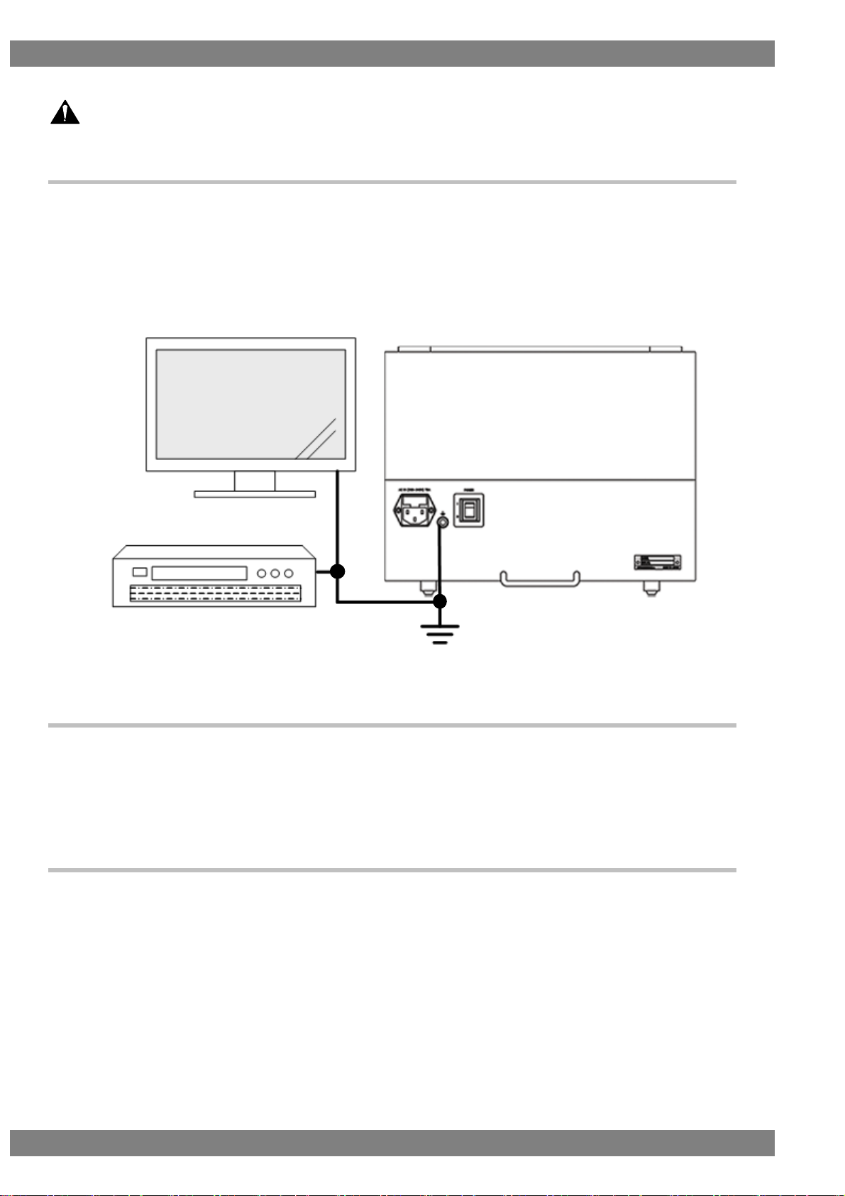
About This Product
■ When connecting this product to another device (TV or DVD player), connect it with
the supplied frame ground (FG) cord, etc. so that the FG is shared between the
device and VA-1842. If this product is used without sharing the FG, there is a risk of
it malfunctioning.
Figure FG Terminal Connection
About Installation
■ Install in a stable location. Also, do not install vertically. There is a risk of a
malfunction due to the temperature rising as a result of heat generation.
About Liquid Crystals
■ Due to the nature of LCD displays, the screen may have a few defective pixels
(always lit or never lit).
■ Do not touch any liquid that may leak from the LCD panel.
If the LCD panel is inadvertently damaged, liquid (liquid crystals) may leak from the panel. Keep the liquid away
from your mouth and skin and do not inhale the vapors. If any liquid crystals should contact your mouth or eyes,
wash them away immediately with water. Furthermore, if any liquid should adhere to your skin or clothing, wipe it
off with alcohol or the like and then wash it away with soap. Your skin or clothing may be damaged if liquid
crystals are left adhered.
Page 15

Before Operation
xi
■ Be careful of glass shards from a broken LCD panel.
If the LCD panel is damaged, take care not to cut your hands, etc. on glass shards.
Touching a broken part may result in an injury.
■ The LCD panel is a high precision device so be careful with regard to the following
points when handling.
・ Wiping with benzene, thinner, etc. will cause deterioration.
・ Leaving water (or salt water) on the LCD panel will cause discoloration
・ If the LCD panel is exposed to direct ultraviolet rays for a long time, the display quality may degrade. For example,
the deflector plate may become brown and the contrast may drop.
・ Moisture from condensation or the like entering inside will cause color irregularities.
・ Directly striking or bumping the LCD panel will cause cracks or other damage.
・ Do not disassemble because getting leaking liquid crystals on your skin is dangerous.
If the Device Malfunctions or Trouble Occurs
■ In the event that a malfunction or trouble occurs, stop using the device, unplug the
power cord, and contact your dealer or an ASTRODESIGN sales representative.
License Notice
HDMI, the HDMI logo and High-Definition Multimedia Interface are trademarks or registered trademarks of HDMI
Licensing LLC.
Page 16

xii
Chapter
Details
Before Operation
Describes safety precautions, configuration of this manual, and the
contents of the product package.
About the VA-1842
Provides an overview and describes the features of the VA-1842.
Connecting with Peripheral
Devices and Usage Examples
Describes the control procedure of the VA-1842.
Menu Configuration
Source ANALYSIS
Signal Generate
Compliance Test
Device Config
Setup
Sub Window
Internal Data
Error List
Describes the functions of the VA-1842.
VA-1842 Specifications
Describes the specifications of the VA-1842.
Details
Quantity
VA-1842 main unit
1
VA-1842 Instruction Manual (this manual PDF) CD
1
USB mouse
1
USB flash memory device
1
Power cable
1
FG cable
1
Product Configuration
The configuration of this product is as follow.
Program data is a combination of two types of data: timing data and pattern data.
Contents of Package
This product includes the following items. Be sure to use the supplied accessories because use of accessories
other than the supplied items may cause a malfunction.
Page 17
1
1
About the VA-1842
1.1 Overview
The HDMI Protocol Analyzer VA-1842 (hereinafter referred to as the VA-1842 in this manual) enables the
protocol parts required in the development of HDMI transmitters to be checked. The HDMI video and audio can
be easily checked with the front LCD monitor and built-in speakers.
Furthermore, you can rewrite the performance information (EDID/SINK) of the VA-1842 unit so various kinds of
receivers (monitors) can be virtualized. The unit can thus be used in, for example, the development of devices
with HDMI terminals such as set-top boxes and DVD players.
In addition, the reception of sink device signals can also be checked by using the VA-1842 Generate function.
This manual collectively refers to devices with HDMI input terminals but without HDMI output terminals such as
monitors and TVs as receivers (monitors), and collectively refers to devices with both HDMI output terminals
and input terminals which perform output based on input signals as repeaters.
1.2 Features
ANALYZE (Measurement) Function
Measures the HDMI and DVI video timing.
Measures each packet content of HDMI.
Checks for differences from HDMI standard values.
Receiver (Monitor) Function
Enables HDMI input to be received.
Through Function
Enables checking the direct exchange of DDC/CEC of source devices and sink devices by allowing
VA-1842 input and output to pass through.
Generate Function
Enables receiving on the sink side to be checked using the timing and multiple patterns built into the
VA-1842. 3D timing can also be output.
Emulator Function
Enables the performance information of the VA-1842 unit to be changed to the performance of
various other monitors (e.g., high-definition TVs and NTSC compatible TVs).
Page 18

2
Built-in LCD Monitor and Speakers
Each of 8-bit, 10-bit, and 12-bit HDMI video can be easily checked with the front LCD monitor.
Linear PCM audio can be easily checked with the built-in speakers.
Program Function
Enables the data used when virtualizing monitors to be managed by programs.
This function allows you to easily change to the performance of various monitors by simply calling
programs.
There is also a function to pick out and group just the programs to be used from among many
programs.
Registration to USB Flash Memory Device
ANALYZE (measurement) data, programs, unit settings, and other data can be saved to the USB
flash memory device.
Hot Plugging Function
Enables a reset to be applied to a transmitter without disconnecting and connecting a cable between
the transmitter and VA-1842.
Log Trigger Function
Enables setting a trigger to retrieve ANALYZE data.
Line Monitor Function
Enables sending and receiving commands with the DDC and CEC lines.
HDMI Version 2.0 Compatible
Supports the timing and InfoFrame of HDMI 2.0.
Page 19
Chapter 1 About VA-1842
3
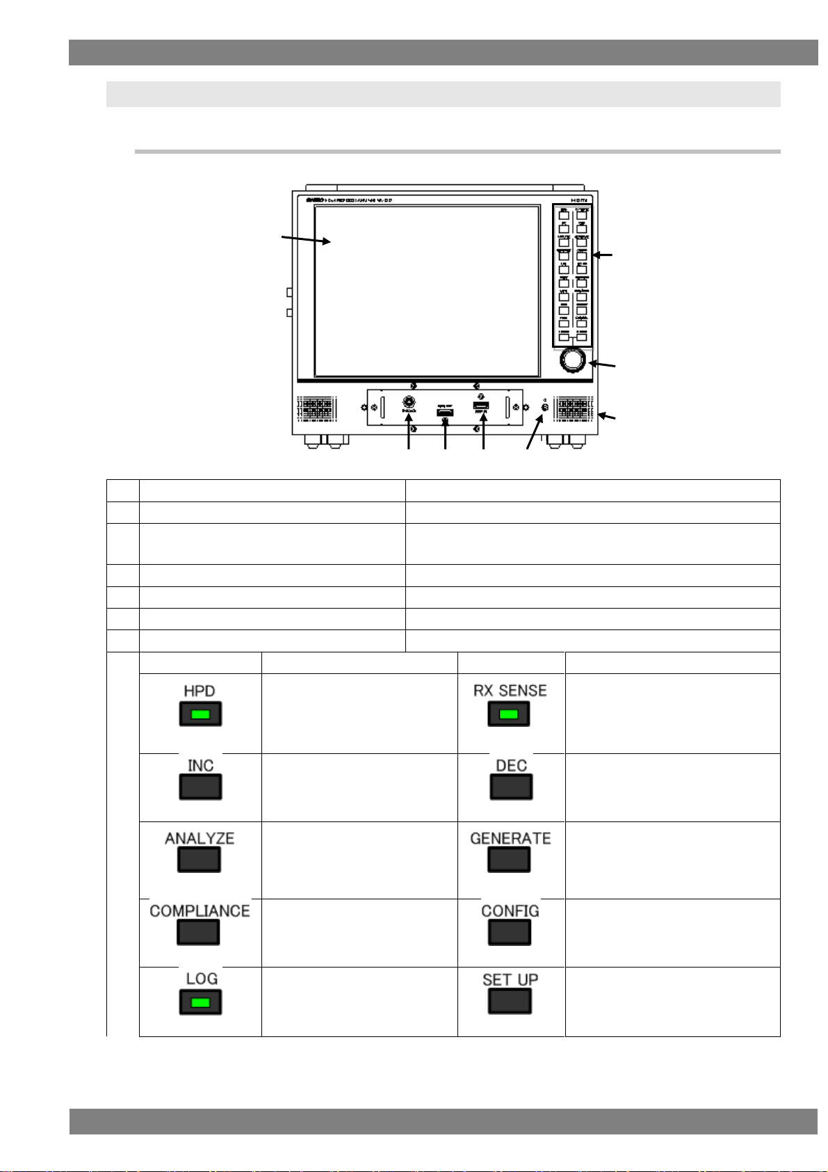
(1)
LCD
Displays the HDMI input video and analysis results.
(2)
HDMI input connector
Inputs the HDMI output of a DVD player or other device.
(3)
HDMI output connector
Outputs the HDMI signals for the input of an HDMI TV, monitor,
or other device.
(4)
HDMI THROUGH connector
Connect a through box for when in THROUGH MODE.
(5)
Speakers
Outputs the audio.
(6)
Headphones connector
Outputs the audio from headphones.
(7)
Joy stick
Operates the cursor in eight directions.
(8)
Key name
Function
Key name
Function
HPD key
When the LED lights, the hot
plug state becomes high.
When the LED goes out, the hot
plug state becomes low.
RX SENSE key
When the LED lights, RX SENSE
turns on.
When the LED goes out, RX
SENSE turns off.
INC key
Used when, for example,
selecting setting items and
parameters.
DEC key
Used when, for example, selecting
setting items and parameters.
ANALYZE key
Opens Source ANALYSIS.
GENERATE key
Opens Signal Generate.
COMPLIANCE key
Displays the Compliance menu.
CONFIG key
Opens Device Config.
LOG key
When the LED lights, acquires
the log.
SET UP key
Opens Setup.
(1)
(2)
(3)
(4)
(5)
(6)
(7)
(8)
1.3 Names and Functions of Parts
1.3.1 VA-1842 Front Panel
Page 20

4
MODE key
Switches between receiver
mode, repeater mode, and
through mode.
FUNCTION key
Performs the function operation of
the active window.
MUTE key
When the LED lights, mutes the
built-in speakers.
When the LED goes out, turns
on the built-in speakers.
RUN/STOP key
Switches between RUN and STOP.
OSD key
When the LED lights, displays
the OSD.
When the LED goes out, hides
the OSD.
PICTURE key
When the LED lights, displays the
input video.
When the LED goes out, hides the
input video.
HELP key
When the LED lights, displays
HELP.
ESC/DEL key
Closes the currently active window.
L CLICK key
Performs the confirm operation.
R CLICK key
Displays a sub window.
Page 21
Chapter 1 About VA-1842
5
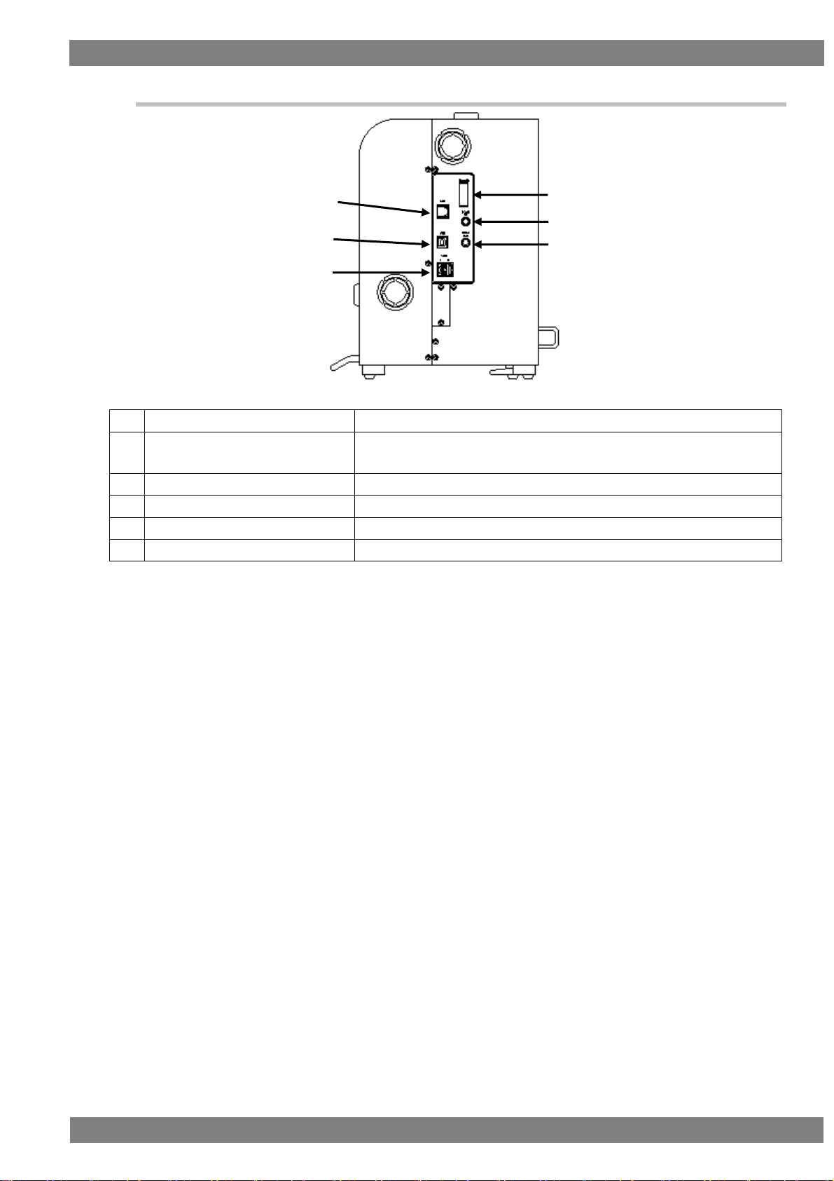
(1)
Ethernet port
This port is for connecting to a LAN with an Ethernet cable.
(2)
USB port (B)
This port enables connecting with a PC to control the VA-1842 by sending
and receiving commands.
(3)
USB port (A)
Connect the mouse or USB flash memory device.
(4)
TRIGGER
Outputs TRIGGER or I2S.
(5)
Coaxial input
This connector is for inputting digital audio.
(6)
Coaxial output
This connector is for outputting digital audio.
(1)
(2)
(3)
(4)
(5)
(6)
1.3.2 VA-1842 Side Panel
Page 22
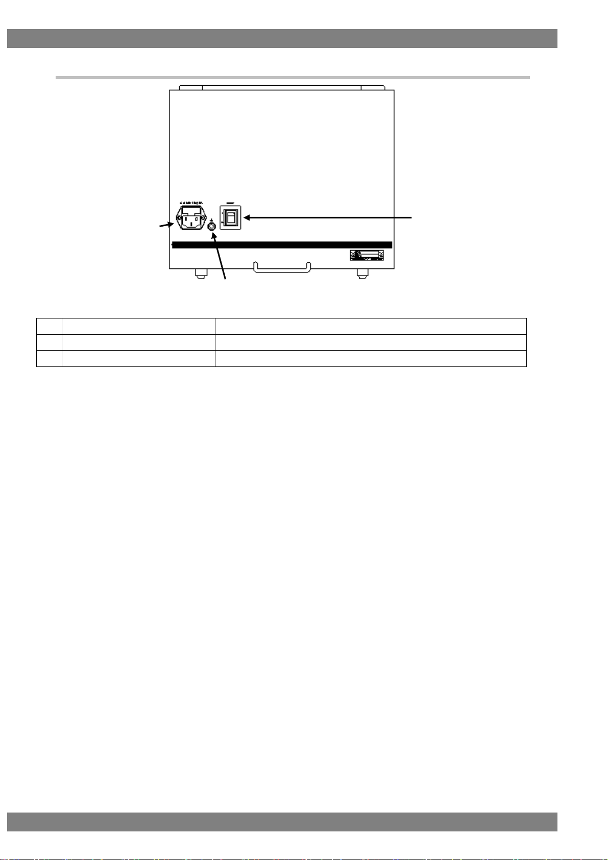
6
(1)
Power switch
Turns the power of the VA-1842 on/off.
(2)
Frame ground (FG)
Shares the FG of a device to be connected with the VA-1842.
(3)
AC input connector
Connect the power cable.
(1)
(2)
(3)
1.3.3 VA-1842 Rear Panel
Page 23
Chapter 1 About VA-1842
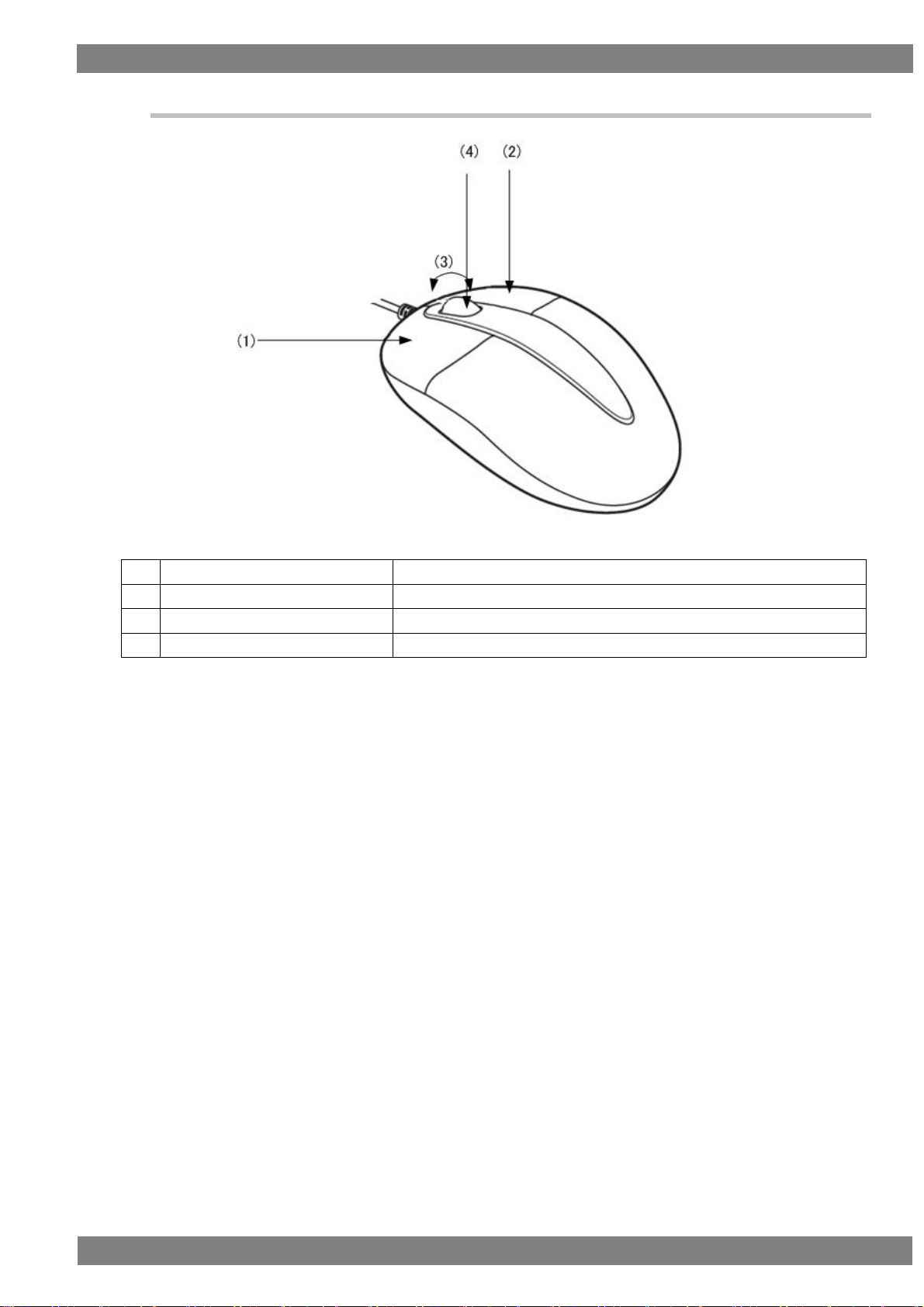
7
(1)
Left-click
Performs the same operation as the L CLICK key.
(2)
Right-click
Performs the same operation as the R CLICK key.
(3)
Wheel scroll
Scrolls the active window up/down.
(4)
Wheel click
Performs the same operation as the FUNCTION key.
1.3.4 Mouse Operation
Page 24
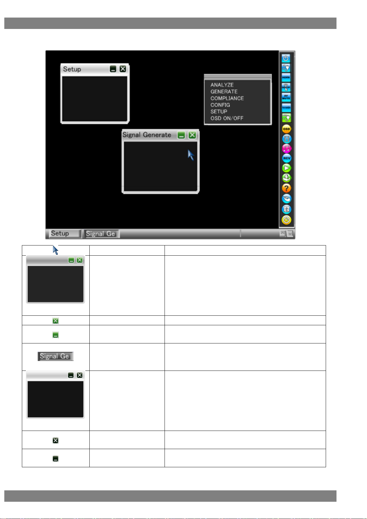
8
Cursor
Operated with the mouse or joy stick.
Active window
This window is currently being used.
It can be moved up, down, left, or right, and can be enlarged or
reduced.
* Up to five windows including the active window can be
displayed.
Active window close button
Closes the active window.
Active window minimize
button
Minimizes the active window.
Active taskbar button
This is the taskbar button for the active window.
Inactive window
This window is currently not being used.
Inactive window close
button
Closes the inactive window.
Inactive window minimize
button
Minimizes the inactive window.
OSD display
Page 25

Chapter 1 About VA-1842
9
Inactive taskbar button
This is the taskbar button for the inactive window.
Menu window
Displayed by right-clicking or pressing R CLICK outside of a
window.
Page 26
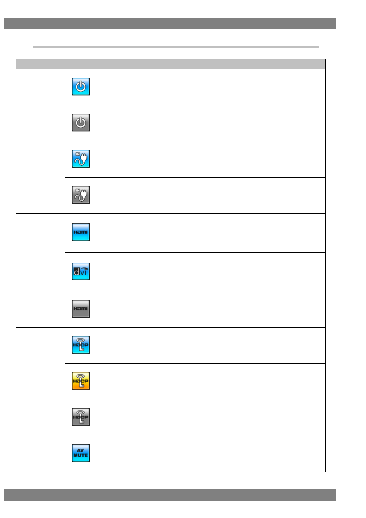
10
Name
Icon
Overview
Video signal input
icon
Video signals are always input when this is in the blue state.
The input of video signals is stopped when this is in the gray state.
Input hot plug
icon
This is displayed in blue when the hot plug state of the input side is high.
This is displayed in gray when the hot plug state of the input side is low.
Input signal
Format icon
A blue HDMI icon is displayed when the input signal format is HDMI.
Clicking the icon or pressing the L CLICK button displays the currently input simple video
timing and color signal.
* Not displayed when the clock is displayed.
A blue DVI icon is displayed when the input signal format is DVI.
Clicking the icon or pressing the L CLICK button displays the currently input simple video
timing and color signal.
* Not displayed when the clock is displayed.
A gray HDMI icon is displayed when there is no input signal.
HDCP icon
This is displayed in blue when HDCP is being applied to the input video.
This is displayed in yellow when the initial authentication of HDCP is starting.
This is displayed in gray when HDCP is not being applied to the input video.
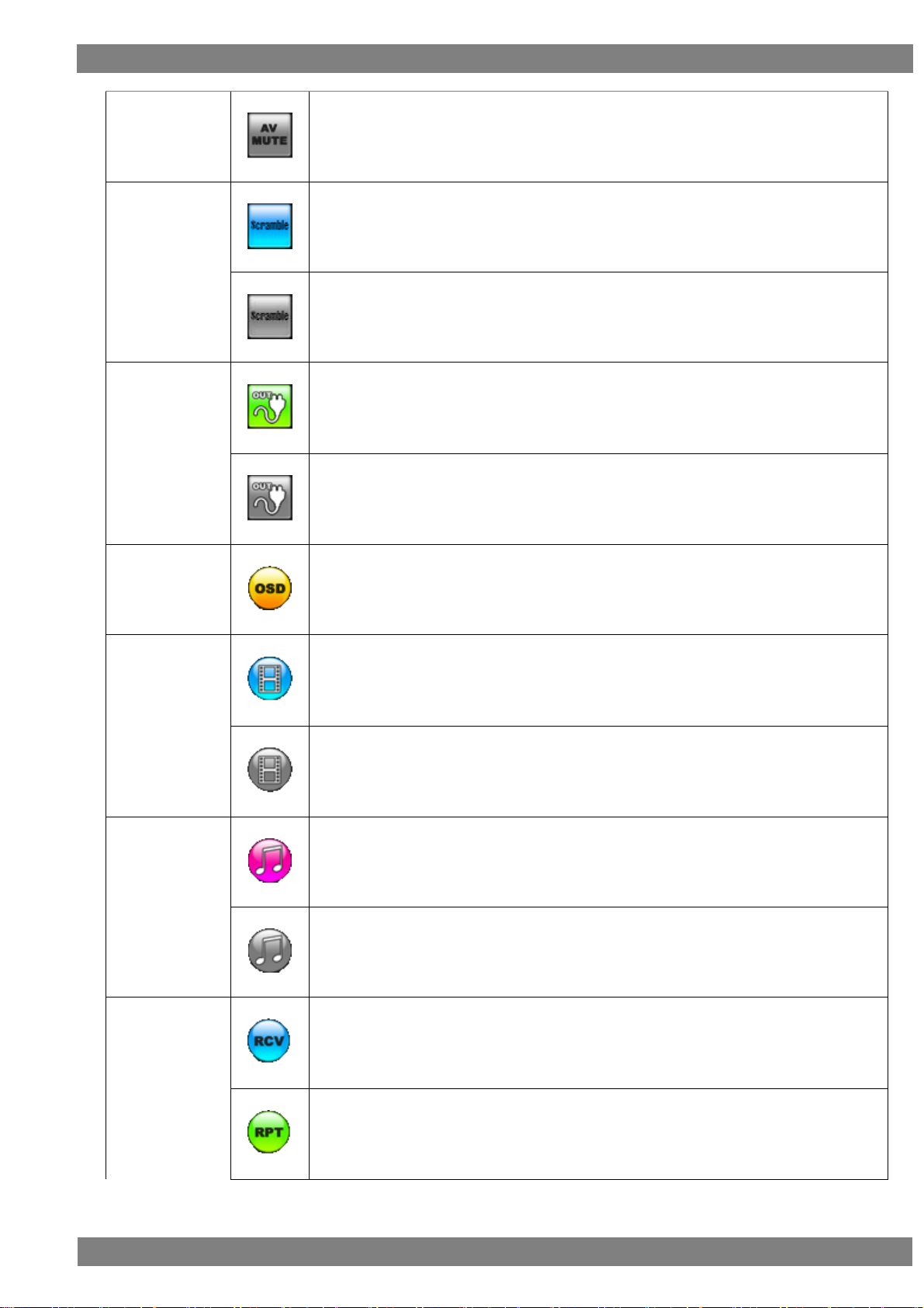
AV MUTE icon
This is displayed in blue when AV mute is on.
1.3.5 Icons
Page 27
Chapter 1 About VA-1842
11
This is displayed in gray when AV mute is off.
Scramble icon
This is displayed in blue when scramble is on.
This is displayed in gray when scramble is off.
Output hot plug
icon
This is displayed in green when the hot plug state of the output side is high.
This is displayed in gray when the hot plug state of the output side is low.
OSD icon
Clicking or pressing the L CLICK button over the OSD icon hides the OSD display.
(In the hidden state, clicking or pressing the L CLICK button again displays the OSD.)
PICTURE icon
The input video is displayed when the icon is blue.
The input video is not displayed when the icon is gray.
Speakers Icon
This is displayed in pink when built-in speaker audio is being output.
This is displayed in gray when built-in speaker audio is muted.
MODE icon
This is displayed in blue when in receiver mode.
This is displayed in green when in repeater mode.
Page 28

12
This is displayed in yellow when in through mode.
RUN/STOP
icon
The RUN/STOP icon is displayed in green when RUN (update) is selected.
The RUN/STOP icon is displayed in red when STOP (update) is selected.
LOG icon
This is displayed in green when acquiring the log.
This is displayed in gray when log acquisition is stopped.
HELP icon
When this is displayed in yellow, aligning the cursor with an error item displays the details.
When this is displayed in gray, error details are hidden.
Mouse icon
This is displayed in blue when the mouse is connected to USB port (A).
This is displayed in gray when the mouse is disconnected from USB port (A).
USB icon
This is displayed in blue when the USB flash memory device is connected to USB port (A).
This is displayed in gray when the USB flash memory device is disconnected from USB port
(A).
Clock icon
Clicking or pressing the L CLICK button over the clock icon displays the current time.
(The clock settings can be set in Device Information of the SETUP menu.)
Clicking while the clock is displayed hides the clock display.
* Not displayed when the simple video timing by an input signal and the color signal are
displayed.
Page 29
13
2
Connecting with Peripheral
Devices and Usage Examples
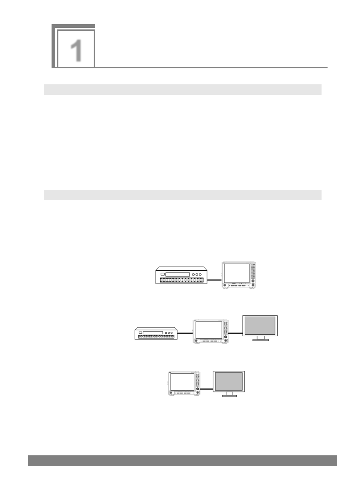
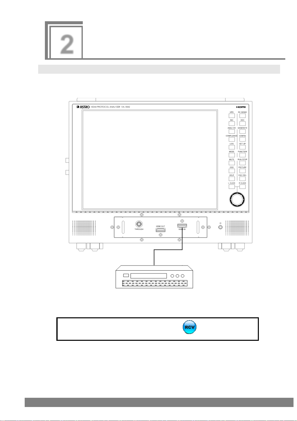
When you will use the VA-1842 as a receiver, select the icon before use.
Device with HDMI output terminal
DVD player, etc.
2.1 Connection Example in Receiver Mode
Set the VA-1842 as a receiver (monitor) to perform HDMI protocol analysis of an HDMI output device.
Measurement of the timing can be performed even for DVI output devices without an HDMI function.
Page 30
14
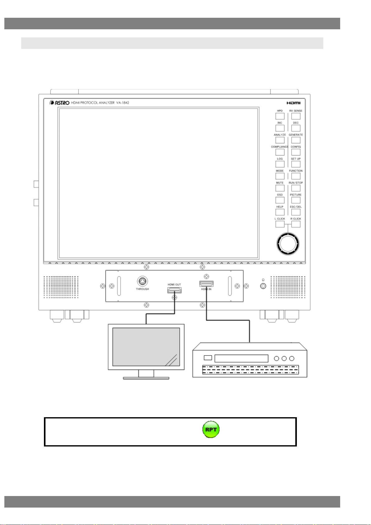
When you will use the VA-1842 as a repeater, select the icon before use.
Device with HDMI output terminal
DVD player, etc.
Device with HDMI input
terminal
LCD TV, etc.
2.2 Connection Example in Repeater Mode
Set the VA-1842 as a repeater to perform HDMI protocol analysis of an HDMI output device.
By connecting an HDMI compatible monitor to the HDMI output of the VA-1842, you can check that an output
device is operating normally as repeater support.
Page 31

Chapter 2 Connecting with Peripheral Devices and Usage Examples
15
When you will use the VA-1842 in through mode, select the icon before use.
Device with HDMI input terminal
LCD TV, etc.
Device with HDMI output terminal
DVD player, etc.
2.3 Connection Example in Through Mode
Set the VA-1842 to through mode to perform DDC and CEC line analysis of an HDMI input/output device.
By connecting a through box to the HDMI THROUGH connector of the VA-1842, you can check that an HDMI
input/output device is operating normally.
Also, the DDC and CEC lines can be monitored to check the direct exchange of input devices and output devices.
Page 32

16
Device with HDMI input terminal
LCD TV, etc.
2.4 Connection Example when Generate
Generate video signals from the VA-1842 and measure the display of HDMI compatible monitors.
∗ This can be used only in receiver mode.
Page 33

17
3
Menu Configuration
Right-clicking or pressing R CLICK opens the window shown in the figure below so that you can select a menu.
An overview of the menu configuration is shown in the following figure.
Clicking or pressing L CLICK over OSD ON/OFF turns OSD display off.
Page 34

18
Mouse operation
Right-click → left-click ANALYZE
Unit operation
Press the ANALYZE key. Or press R CLICK → press L CLICK over ANALYZE
3.1 ANALYZE
Use the ANALYZE menu when measuring input HDMI states.
Page 35

Chapter 3 Menu Configuration
19
Mouse operation
Right-click → left-click GENERATE
Unit operation
Press the GENERATE key. Or press R CLICK → press L CLICK over GENERATE
3.2 GENERATE
Use the GENERATE menu when generating video signals.
Page 36

20
Mouse operation
Right-click → left-click COMPLIANCE
Unit operation
Press the COMPLIANCE key. Or press R CLICK → press L CLICK over COMPLIANCE
3.3 COMPLIANCE
Page 37

Chapter 3 Menu Configuration
21
Mouse operation
Right-click → left-click CONFIG
Unit operation
Press the CONFIG key. Or press R CLICK → press L CLICK over CONFIG
3.4 CONFIG
Page 38

22
Mouse operation
Right-click → left-click SETUP
Unit operation
Press the SETUP key. Or press R CLICK → press L CLICK over SETUP
3.5 SETUP
Page 39

23
4
Source ANALYSIS
You can measure the timing of HDMI signals and decode and display InfoFrame and other content.
The items of the measurement result display part are as shown in the following figure.
Page 40

24
Mouse operation
Right-click → left-click ANALYZE → left-click Video Timing
Unit operation
Press the ANALYZE key.
→ press L CLICK over Video Timing
Press R CLICK → press L CLICK over ANALYZE
4.1 ANALYZE
4.1.1 Video Timing
Measures the timing of input.
The display method is as follows.
Page 41

Chapter 4 Source ANALYSIS
25
Item
Period
Details
Clock Change
Presence or absence of changing after pressing "Clear"
Pixel Clock
Pixel frequency
H Frequency
HSYNC frequency
V Frequency
VSYNC frequency
H Total Pixels
HT
HTOTAL width
H Active Pixels
HD
HDISP width
H Sync Pixels
HS
HSYNC width
H Back Porch Pixels
HB
HSYNC back porch width
H Front Porch Pixels
HF
HSYNC front porch width
H Sync Polarity
HSYNC polarity
V Total Lines
VT
VTOTAL width (1 frame unit)
V Active TOTAL
VD(VD1+VD2)
VDISP width (1 frame unit)
V Active Field1
VD(1)
VDISP width
1 frame unit when noninterlace, and value of 1st
field when interlace.
V Sync Field1
VS(1)
VSYNC width
V Back Porch Field1
VB(1)
VSYNC back porch width
V Front Porch Field1
VF(1)
VSYNC front porch width
HV Sync OffSet1
H and V phase difference
V Active Field2
VD2
VDISP width of 2nd field when interlace
V Sync Field2
VS2
VSYNC width of 2nd field when interlace
V Back Porch Field2
VB2
VSYNC back porch width of 2nd field when interlace
V Front Porch Field2
VF2
VSYNC front porch width of 2nd field when interlace
HV Sync OffSet2
H and V phase difference of 2nd field when interlace
V Sync Polarity
VSYNC polarity
Interlace
Interlace or non-interlace
V Active L ODD
VDISP width of L ODD side when field alternative
V Active R ODD
VDISP width of R ODD side when field alternative
V Blank3 ODD
VBlank3 width of ODD side when field alternative
V Active L EVEN
VDISP width of L EVEN side when field alternative
V Active R EVEN
VDISP width of R EVEN side when field alternative
V Blank3 EVEN
VBlank3 width of EVEN side when field alternative
Page 42

26
VS VB VD VF
VT
Data Enable
HSYNC
VSYNC
VS1 VB1
VD1 VF2
VT
Data
Enable
HSYNC
VSYNC
VD2VF1 VS2
VB
2
HS HB HD HF
HT
Data
Enable
HSYNC
Horizontal Synchronization Signal
Vertical Synchronization Signal (when Non-Interlaced)
Vertical Synchronization Signal (when Interlaced)
Page 43

Chapter 4 Source ANALYSIS
27
Mouse operation
Right-click → left-click ANALYZE → left-click AVI InfoFrame
Unit operation
Press the ANALYZE key.
→ press L CLICK over AVI InfoFrame
Press R CLICK → press L CLICK over ANALYZE
Displayed item
Description
Status Change
Presence or absence of changing after pressing
"Clear"
Type Code
82 H
Version Number
XX H
Length of InfoFrame
XX H
Checksum
XX H
4.1.2 AVI InfoFrame
Decodes and displays AVI InfoFrame of the HDMI input.
AVI stands for Auxiliary Video Information, and refers to the information about the video output by the transmitter
which is input.
The display method is as follows.
Also, you can switch between HEX and GUI display by right-clicking over the window and then clicking HEX<>GUI.
The AVI InfoFrame display items when GUI display are as follows.
Page 44

28
Scan Information
No Data
Overscanned
Underscanned
Future
Bar Information
Bar Data not valid
Vert.Bar Info valid
Horiz. Bar Info valid
Vert. and Horiz. Bar Info valid
Active Format Present
No Active Format Information valid
Active Format Information valid
RGB or YCbCr
RGB
YCbCr4:2:2
YCbCr4:4:4
YCbCr4:2:0
Active Format Aspect
Same as picture aspect ratio
4:3
16:9
14:9
box 16:9
box 14:9
box > 16:9
4:3 (H Just)
16:9 (14:9 V Just)
16:9 (4:3 V Just)
reserved
Picture Aspect
No Data
4:3
16:9
Future
Colorimetry
No Data
SMPTE 170M / ITU601
ITU709
Extended Colorimetry Valid
Non-uniform Scaling
Unknown
Scaled H
Scaled V
Scaled H&V
RGB Quantization Range
Default
Limited Range
Full Range
Reserved
Extended Colorimetry
xvYCC601
xvYCC709
SYCC601
AdobeYCC601
Page 45

Chapter 4 Source ANALYSIS
29
AdobeRGB
ITU-R BT.2020 Y'cC'bcC'rc
ITU-R BT.2020 R'G'B' or Y'C'bC'r
IT content
No data
IT content
Video Code
[X] XXX x XXX @ XXX / XXX Hz X : X
Reserved
No Video Code Available
Repetition
No Repetition
pixel sent X times
Reserved
IT Content Type
Graphics
Photo
Cinema
Game
YCC Quantization Range
Limited Range
Full Range
Reserved
Reserved
Line Number of End of Top Bar (ETB)
0 to FFFF
Line Number of Start of Bottom Bar (SBB)
0 to FFFF
Pixel Number of End of Top Bar (ELB)
0 to FFFF
Pixel Number of Start of Bottom Bar
(SRB)
0 to FFFF
Rsv of Data Byte1
NO ERROR
ERROR
Rsv of Data Byte4
NO ERROR
ERROR
Page 46

30
Mouse operation
Right-click → left-click ANALYZE → left-click SPD InfoFrame
Unit operation
Press the ANALYZE key.
→ press L CLICK over SPD InfoFrame
Press R CLICK → press L CLICK over ANALYZE
Displayed item
Description
Status Change
Presence or absence of changing after pressing "Clear"
Type Code
83 H
Version Number
XX H
Length of InfoFrame
XX H
Checksum
XX H
Vendor Name
(8 characters)
Product Description
(16 characters)
Source Device Info
unknown
Digital STB
DVD
D-VHS
HDD Video
DVC
DSC
Video CD
GAME
PC general
Blu-Ray Disc
Super Audio CD
HD DVD
PMP
Reserved
4.1.3 SPD InfoFrame
Decodes and displays SPD InfoFrame of the HDMI input.
SPD stands for Source Product Description, and refers to the information on the transmitter which is input.
The display method is as follows.
Also, you can switch between HEX and GUI display by right-clicking over the window and then clicking HEX<>GUI.
The SPD InfoFrame display items when GUI display are as follows.
Page 47

Chapter 4 Source ANALYSIS
31
Mouse operation
Right-click → left-click ANALYZE → left-click Audio InfoFrame
Unit operation
Press the ANALYZE key.
→ press L CLICK over Audio
InfoFrame
Press R CLICK → press L CLICK over ANALYZE
Displayed item
Description
Status Change
Presence or absence of changing after pressing "Clear"
Type Code
84 H
Version Number
XX H
Length of InfoFrame
XX H
Checksum
XX H
Audio Coding Type
Refer to Stream Header
IEC60958 PCM
AC-3
MPEG1(Layers 1 & 2)
MP3(MPEG1 Layer 3)
4.1.4 Audio InfoFrame
Decodes and displays Audio InfoFrame of the HDMI input.
For Audio InfoFrame, the information about the audio output by the transmitter is input.
The display method is as follows.
Also, you can switch between HEX and GUI display by right-clicking over the window and then clicking HEX<>GUI.
The Audio InfoFrame display items when GUI display are as follows.
Page 48

32
MPEG2(multichannel)
AAC
DTS
ATRAC
One Bit Audio
Dolby Digital+
DTS-HD
MLP
DST
WMA Pro
Reserved
Audio Channel Count
Refer to Stream Header
2 - 8ch
Sampling Frequency
Refer to Stream Header
32 kHz
44.1 kHz
48 kHz
88.2 kHz
96 kHz
176.4 kHz
192 kHz
Sample Size
Refer to Stream header
16 bit
20 bit
24 bit
Speaker Placement
TC FCH FLH FRH FLW FRW FRC FLC RR RL FC LFE
FR FL (Refer to the standards.)
Reserved
Level Shift Value
0 - 15dB
Down-mix Inhibit Flag
Permitted or No information
Prohibited
Format Code Extension
Refer to Audio Coding Type
HE-AAC
HE-AACv2
MPEG Surround
Reserved
LFE Playback Level
Unknown or refer to other information
0 dB playback
+10 dB playback
Reserved
Rsv of Data Byte1
NO ERROR
ERROR
Rsv of Data Byte2
NO ERROR
ERROR
Rsv of Data Byte3
NO ERROR
ERROR
Page 49

Chapter 4 Source ANALYSIS
33
Rsv of Data Byte6
NO ERROR
ERROR
Rsv of Data Byte7
NO ERROR
ERROR
Rsv of Data Byte8
NO ERROR
ERROR
Rsv of Data Byte9
NO ERROR
ERROR
Rsv of Data Byte10
NO ERROR
ERROR
Page 50

34
Mouse operation
Right-click → left-click ANALYZE → left-click MPEG InfoFrame
Unit operation
Press the ANALYZE key.
→ press L CLICK over MPEG
InfoFrame
Press R CLICK → press L CLICK over ANALYZE
Displayed item
Description
Status Change
Presence or absence of changing after pressing "Clear"
Type Code
85 H
Version Number
XX H
Length of InfoFrame
XX H
Checksum
XX H
MPEG Bit Rate
X M XXX k XXXX Hz
Field Repeat
New Field (picture)
Repeated Field
MPEG Frame
Unknown (No Data)
I Picture
B Picture
P Picture
Rsv of Data Byte6
NO ERROR
ERROR
Rsv of Data Byte7
NO ERROR
ERROR
Rsv of Data Byte8
NO ERROR
ERROR
4.1.5 MPEG InfoFrame
Decodes and displays MPEG InfoFrame of the HDMI input.
For MPEG InfoFrame, if the video sent by the transmitter has been converted from compressed video to noncompressed video, the video information of the compressed video is input.
The display method is as follows.
Also, you can switch between HEX and GUI display by right-clicking over the window and then clicking HEX<>GUI.
The Audio InfoFrame display items when GUI display are as follows.
Page 51

Chapter 4 Source ANALYSIS
35
Rsv of Data Byte9
NO ERROR
ERROR
Rsv of Data Byte10
NO ERROR
ERROR
Page 52

36
Mouse operation
Right-click → left-click ANALYZE → left-click Vendor Specific InfoFrame
Unit operation
Press the ANALYZE key.
→ press L CLICK over Vendor Specific
InfoFrame
Press R CLICK → press L CLICK over ANALYZE
Displayed item
Description
Status Change
Presence or absence of changing after pressing
"Clear"
Multi Packet No
No 1 / No 2 / No 3
Type Code
81 H
Version Number
XX H
Length of InfoFrame
XX H
Checksum
XX H
IEEE Registration ID
XXXXXX H
VSIF Format
H14b VSIF
HF-VSIF
Other
4.1.6 Vendor Specific InfoFrame
Decodes and displays Vendor Specific InfoFrame of the HDMI input.
With Vendor Specific InfoFrame, information about the 3D format and 4Kx2K is input.
The display method is as follows.
Also, you can switch between HEX and GUI display by right-clicking over the window and then clicking HEX<>GUI.
The Vendor Specific InfoFrame display items when GUI display are as follows.
Page 53

Chapter 4 Source ANALYSIS
37
IEEE Registration ID = 000C03 H
HDMI_Video_Format
no video format
Extended resolution format
3D format
Reserved
HDMI_Video_Format = Extended resolution format
HDMI_VIC
4Kx2K 29.97/30Hz
4Kx2K 25Hz
4Kx2K 23.98/24Hz
4Kx2K 24Hz(SMPTE)
Reserved
HDMI_Video_Format = 3D format
3D_Structure
Frame packing
Field alternative
Line alternative
Side-by-Side(Full)
L + depth
L + depth + graphics + graphics-depth
Top-and-Bottom
Side-by-Side(Half)
Reserved
3D_Meta_present
0H or 1H
3D_Structure = side-by-side(half)
3D_Ext_Data
Horizontal Odd/Left Odd/Right
Horizontal Odd/Left Even/Right
Horizontal Even/Left Odd/Right
Horizontal Even/Left Even/Right
Quincunx Odd/Left Odd/Right
Quincunx Odd/Left Even/Right
Quincunx Even/Left Odd/Right
Quincunx Even/Left Even/Right
Reserved
3D_Meta_present = 1H
3D_Metadata_type
XX H
3D_Metadata_Length
XX H
3D_Metadata_1~20
XX H
IEEE Registration ID = C45DD8 H
Version
XX
3D_Valid
0H or 1H
3D_Valid = 1
3D_F_Structure
Frame packing
Field alternative
Line alternative
Side-by-Side(Full)
L + depth
L + depth + graphics + graphics-depth
Page 54

38
Top-and-Bottom
Side-by-Side(Half)
Reserved
3D_Meta_present
Not Present or Present
3D_Additionalinfo_present
Not Present or Present
3D_DisparityData_present
Not Present or Present
3D_F_Structure = side-by-side(half)
3D_Ext_Data
Horizontal Odd/Left Odd/Right
Horizontal Odd/Left Even/Right
Horizontal Even/Left Odd/Right
Horizontal Even/Left Even/Right
Quincunx Odd/Left Odd/Right
Quincunx Odd/Left Even/Right
Quincunx Even/Left Odd/Right
Quincunx Even/Left Even/Right
Reserved
3D_ Additionalinfo_present = Present
3D_DualView
Normal 3D or DualView
3D_ViewDependency
No Indication
The right view originates
The left view originates
Both views
3D_Preferred2DView
No Indication
Use right 3D view
Use left 3D view
Don’t Care
3D_DisparityData_present = Present
3D_DisparityData_version
X
3D_DisparityData_lenght
X
3D_Disparitydata_1~18
XX H
3D_Meta_present = 1H
3D_Metadata_type
XX H
3D_Metadata_Length
XX H
3D_Metadata_1~20
XX H
Page 55

Chapter 4 Source ANALYSIS
39
Mouse operation
Right-click → left-click ANALYZE → left-click Dynamic Range and Mastering InfoFrame
Unit operation
Press the ANALYZE key.
→ press L CLICK over Dynamic
Range and Mastering InfoFrame
Press R CLICK → press L CLICK over ANALYZE
Displayed item
Description
Status Change
Presence or absence of changing after pressing "Clear"
Type Code
87 H
Version Number
XX H
Length of InfoFrame
XX H
Checksum
XX H
EOTF
Traditional gamma - SDR Luminance Range
Traditional gamma - HDR Luminance Range
SMPTE ST 2084[2]
Hybrid Log-Gamma
Reserved
Static_Metadata_Discriptor_ID
Static Metadata Type1
Reserved
display_primaries_x0
X.XXXXX
display_primaries_y0
X.XXXXX
display_primaries_x1
X.XXXXX
display_primaries_y1
X.XXXXX
display_primaries_x2
X.XXXXX
4.1.7 Dynamic Range and Mastering InfoFrame
Decodes and displays Dynamic Range and Mastering InfoFrame of the HDMI input.
For Dynamic Range and Mastering InfoFrame, the HDR type and other related information are input.
The display method is as follows.
Also, you can switch between HEX and GUI display by right-clicking over the window and then clicking HEX<>GUI.
The Gamut Metadata Packet display items when GUI display are as follows.
Page 56

40
display_primaries_y2
X.XXXXX
white_point_x
X.XXXXX
wite_point_y
X.XXXXX
max_dispay_mastering_luminance
XXXXXX cd/m2
min_dispay_mastering_luminance
X.XXXXX cd/m2
Maximu Content Light Level
XXXXXX cd/m2
Maximu Frame-average Light Level
XXXXXX cd/m2
Page 57

Chapter 4 Source ANALYSIS
41
Mouse operation
Right-click → left-click ANALYZE → left-click Gamut MetaData Packet
Unit operation
Press the ANALYZE key.
→ press L CLICK over Gamut
MetaData Packet
Press R CLICK → press L CLICK over ANALYZE
Displayed item
Description
Status Change
Presence or absence of changing after pressing "Clear"
Packet Type Code
0A H
Next Field
XX H
No Current GBD
XX H
GBD Profile
P0
P1
P2
P3
Reserved
4.1.8 Gamut MetaData Packet
Decodes and displays Gamut Metadata Packet of the HDMI input.
For Gamut Metadata Packet, Gamut boundary descriptions (GBD) and other related metadata information are
input.
The display method is as follows.
Also, you can switch between HEX and GUI display by right-clicking over the window and then clicking HEX<>GUI.
The Gamut Metadata Packet display items when GUI display are as follows.
Page 58

42
Affected Gamut Seq Num
XX H
Current Gamut Seq Num
XX H
Packet Seq
Intermediate packet in sequence
First packet in sequence
Last packet in sequence
Only packet in sequence
GBD profile = P1 and Packet Seq = First packet in sequence
GBD Length H
XX H
GBD Length L
XX H
Checksum
XX H
Format Flag
Vertices/Facets
Range
GBD Color Precision
8bit
10bit
12bit
Format Flag = Vertices/Facets
GBD Color Space
ITU-R BT.709(using RGB)
xvYCC601(IEC 61966-2-4-SD)(using YCbCr)
xvYCC709(IEC 61966-2-4-HD)(using YCbCr)
XYZ
Format Flag = Range
GBD Color Space
Reserved
RGB expression of xvYCC601
RGB expression of xvYCC709
Reserved
Format Flag = Vertices/Facets
Facet Mode
0 or 1
Number Vertices H
XX H
Number Vertices L
XX H
Packed GBD Vertices
Data
±X.XX
Format Flag = Range
Packed Range Data
±X.XX
Gamut Rsv pb0
XX H
Page 59

Chapter 4 Source ANALYSIS
43
Mouse
operation
Right-click → left-click ANALYZE → left-click ACP Packet
Unit operation
Press the ANALYZE key.
→ press L CLICK over ACP Packet
Press R CLICK → press L CLICK over ANALYZE
Displayed item
Description
Status Change
Presence or absence of changing after pressing "Clear"
Packet Type Code
04 H
ACP_Type
Generic Audio
IEC60958-Identified Audio
DVD Audio*1
Super Audio CD*2
Reserved
*1
DVD-Audio_Type
XX H
Copy_Permission
Copy Freely
reserved
audio_copy_number
Can’t copy
Copy_Number
Number of permitted copies is '1'
Number of permitted copies is '2'
Number of permitted copies is '4'
4.1.9 ACP Packet
Decodes and displays ACP Packet of the HDMI input.
ACP stands for Audio Content Protection, and refers to the information for the copyright protection of audio sent
by the transmitter which is input.
The display method is as follows.
Also, you can switch between HEX and GUI display by right-clicking over the window and then clicking HEX<>GUI.
The ACP Packet display items when GUI display are as follows.
*1 is displayed when ACP Type of DVD Audio, and *2 is displayed when ACP Type is Super Audio CD.
Page 60

44
Number of permitted copies is '6'
Number of permitted copies is '8'
Number of permitted copies is '10'
Number of permitted copies is '3'
Number of permitted copy is not restricted. (Copy One
Generation)
Quality
CH < 2, fs < 48kHz, Q < 16bits
CH < 2, fs&Q is not restricted
CH&fs&Q is not restricted
CH is not restricted, fs < 48kHz, Q < 16bits
Transaction
not present
reserved
Rsv of Header Byte2
NO ERROR
ERROR
Rsv of Data Byte2-27
NO ERROR
ERROR
*2
Count_A
XX times
Count_S
XX times
Count_U
XX times
CCI_Flags Q_A
CD Quality
unlimited DSD quality
CCI_Flags Q_S
CD Quality
unlimited DSD quality
CCI_Flags Q_U
CD Quality
unlimited DSD quality
CCI_Flags Move_A
not allowed for the content
allowed for the content
CCI_Flags Move_S
not allowed for the content
allowed for the content
CCI_Flags Move_U
not allowed for the content
allowed for the content
CCI_Flags Reserved
NO ERROR
ERROR
CCI Rsv of Data Byte5-16
NO ERROR
ERROR
Rsv of Data Byte17-27
NO ERROR
ERROR
Page 61

Chapter 4 Source ANALYSIS
45
Mouse operation
Right-click → left-click ANALYZE → left-click ISRC1 Packet
Unit operation
Press the ANALYZE key.
→ press L CLICK over ISRC1 Packet
Press R CLICK → press L CLICK over ANALYZE
Displayed item
Description
Status Change
Presence or absence of changing after pressing "Clear"
Packet Type Code
05H
ISRC_Cont
XX H
ISRC_Valid
XX H
ISRC_Status
XX H
Validity information
0H UPC/EAN and ISRC are invalid
4H UPC/EAN is invalid and ISRC is valid
8H UPC/EAN is valid and ISRC is invalid
CH UPC/EAN and ISRC are valid
Catalogue code (UPC/EAN #1- #13)
XXXXXXXXXXXXX H
Country code (ISRC #1 - #2)
XX
First owner code (ISRC #3 - #5)
XXX
Year of recording code (ISRC #6 - #7)
XX H
Recording code (Recording-item code)
XXXXXH
Rsv of Header Byte1
NO ERROR
ERROR
Rsv of Header Byte2
NO ERROR
ERROR
Rsv of Data Byte16-27
NO ERROR
ERROR
4.1.10 ISRC1 Packet
Decodes and displays ISRC1 Packet of the HDMI input.
ISRC stands for International Standard Recording Code, and refers to the audio source identification code
which is input when the audio sent by the transmitter is DVD Audio. With ISRC1, the values of
UPC_EAN_ISRC_numbers 0 to 15 as defined by the DVD Audio standard are applied in addition to the values
defined by the HDMI standard.
The display method is as follows.
Also, you can switch between HEX and GUI display by right-clicking over the window and then clicking HEX<>GUI.
The ISRC1 Packet display items when GUI display are as follows.
Page 62

46
Mouse operation
Right-click → left-click ANALYZE → left-click ISRC2 Packet
Unit operation
Press the ANALYZE key.
→ press L CLICK over ISRC2 Packet
Press R CLICK → press L CLICK over ANALYZE
Displayed item
Description
Status Change
Presence or absence of changing after pressing "Clear"
Header Byte0-2
Each XXH
Data Byte0-27
Each XXH
NO ISRC2 Packet
4.1.11 ISRC2 Packet
Decodes and displays ISRC2 Packet of the HDMI input.
With ISRC2, the values of UPC_EAN_ISRC_numbers 16 to 31 as defined by the DVD Audio standard are
applied. (Currently, these are reserved by the DVD Audio standard.)
The display method is as follows.
Also, you can switch between HEX and GUI display by right-clicking over the window and then clicking HEX<>GUI.
The ISRC2 Packet display items when GUI display are as follows.
Page 63

Chapter 4 Source ANALYSIS
47
Mouse operation
Right-click → left-click ANALYZE → left-click General Control Packet
Unit operation
Press the ANALYZE key.
→ press L CLICK over General
Control Packet
Press R CLICK → press L CLICK over ANALYZE
Displayed item
Description
Status Change
Presence or absence of changing after pressing "Clear"
SET_AVMUTE
ON
OFF
Clear_AVMUTE
ON
OFF
Color Depth
Color Depth not indicated
8bit
10bit
12bit
16bit
Packing Phase
Phase 4
Phase 1
Phase 2
Phase 3
Default_Phase
0 or 1
4.1.12 General Control Packet
Decodes and displays General Control Packet of the HDMI input.
The display method is as follows.
Also, you can switch between HEX and GUI display by right-clicking over the window and then clicking HEX<>GUI.
The General Control Packet display items when GUI display are as follows.
Page 64

48
Mouse operation
Right-click → left-click ANALYZE → left-click Channel Status Bit
Unit operation
Press the ANALYZE key.
→ press L CLICK over Channel Status
Bit
Press R CLICK → press L CLICK over ANALYZE
Displayed item
Description
Professional or Consumer
Professional Mode
Consumer Mode
Audio
linear PCM samples
other than linear PCM samples
Copy / Copyright
copyright
no copyright
Emphasis
Audio = Linear PCM samples
without pre-emphasis
with 50/15 us pre-emphasis
4.1.13 Channel Status Bit
Decodes and displays Channel Status Bit (the sub codes that identify the sending device, sampling frequency,
and so on) of the HDMI input audio streams.
The display method is as follows.
Also, you can switch between HEX and GUI display by right-clicking over the window and then clicking HEX<>GUI.
The Channel Status Bit display items when GUI display are as follows.
Page 65

Chapter 4 Source ANALYSIS
49
Reserved - 2channel audio(0x02)
Reserved - 2channel audio(0x03)
Reserved - 4channel audio
Audio = other than Linear PCM samples
Default state
Channel Status Mode
Mode 00
Reserved
Category code
General. Used temporarily
Laser optical (Compact disc)
Laser optical (Laser optical digital audio system)
Laser optical (Mini disc system)
Laser optical (Digital versatile disc)
Laser optical (Reserved)
Digital/digital conv.&signal (PCM encoder/decoder)
Digital/digital conv.&signal (Digital signal mixer)
Digital/digital conv.&signal (Sampling rate converter)
Digital/digital conv.&signal (Digital sound sampler)
Digital/digital conv.&signal (Digital sound processor)
Digital/digital conv.&signal (Reserved)
Digital compact cassette
Magnetic tape or disc (DAT)
Magnetic tape or disc (Video tape recorder)
Magnetic tape or disc (Digital compact recorder)
Magnetic tape or disc (Reserved)
Broadcast reception (Japan)
Broadcast reception (Europe)
Broadcast reception (USA)
Broadcast reception (Electronic software delivery)
Broadcast reception (Reserved)
Without copyright information(Synthesizer)
Without copyright information(Microphone)
Without copyright information(Reserved)
Category code without copyright(A/D converter)
Category code without copyright(Reserved)
Category code with copyright(A/D converter)
Category code with copyright(Reserved)
Category code groups for solid state memory
(Reserved)
Experiment products not for commercial sale
Not define. Reserved
L(Generation Status) Bit
0 - 1
Source number
Do not take into account.
1 - 15 CH
Channel number
Do not take into account.
A - O (0x1:A; 0x2:B; …… 0xF:O)
Sampling frequency
no indicate
32kHz
Page 66

50
44.1kHz
48kHz
88.2kHz ( - HDMI Original )
96kHz ( - HDMI Original )
176.4kHz ( - HDMI Original )
192kHz ( - HDMI Original )
768kHz
Reserved
Clock accuracy
Level 2, ±1000ppm (default)
Level 3, variable pitch
Level 1, ±50ppm - high accuracy
Reserved
Maximum sample length
20bits
24bits
Sample word length
Maximum audio sample word length = 20 bit
Word length not indicated (default )
16bits
18bits
19bits
20bits
17bits
Reserved
Maximum audio sample word length = 24 bit
Word length not indicated (default )
20bits
22bits
23bits
24bits
21bits
Reserved
Rsv of Data
CSB Repetition Period
NO ERROR
ERROR
Audio FIFO ERROR
NO ERROR
ERROR
AudioPLL Lock ERROR
NO ERROR
ERROR
Page 67

Chapter 4 Source ANALYSIS
51
Mouse operation
Right-click → left-click ANALYZE → left-click Audio Timing
Unit operation
Press the ANALYZE key.
→ press L CLICK over Audio Timing
Press R CLICK → press L CLICK over ANALYZE
Displayed item
Description
N
Indication (DEC) of each register value
CTS
Audio Type
Audio Sample
One Bit Audio
High Bitrate Audio
CH1
Volume of each channel (This can be switched between dB display (figure
on left above) and value display (figure on right above) in Sub Window of
Audio Timing of Sub Window.)
CH2
CH3
CH4
CH5
CH6
CH7
CH8
4.1.14 Audio Timing
Displays the constants (N and CTS) used when playing back the HDMI input audio clock from the video pixel
clock and the input HDMI audio volume level.
The display method is as follows.
The Audio Timing display items when GUI display are as follows.
Page 68

52
Mouse operation
Right-click → left-click ANALYZE → left-click HDCP Status
Unit operation
Press the ANALYZE key.
→ press L CLICK over HDCP Status
Press R CLICK → press L CLICK over ANALYZE
Displayed item
Description
HDCP1.4
AN
Pseudo-random value used for HDCP authentication that is sent from the
transmitter to the VA-1842
AKSV
Key Selection Vector of the sender side
BKSV
Key Selection Vector of the VA-1842
Ri’
Authentication value calculated by VA-1842
Bcaps
HDMI mode, repeater support, etc.
BSTATUS1(Count)
Total number of devices connected to downstream *
BSTATUS2(Depth)
Total number of stages connected to downstream *
KSVFIFO
KSV values of the devices connected to downstream that have been
collected by the VA-1842 *
V’
Value for judging whether or not the KSV list generated by the VA-1842 is
appropriate *
HDCP2.2
ReceiverID
Receiver ID of the VA-1842 read with certrx of AKE_Send_Cert
TXCAPS
Version information sent with AKE_Init
rtx
Pseudo-random value sent with AKE_Init
RXCAPS
Version information and repeater status read with AKE_Send_Cert
rrx
Pseudo-random value read with AKE_Send_Cert
Ekpub_km
Master key information sent with No_Stored_km
Ekh_km
Master key information sent with Stored_km
rn
Pseudo-random nonce sent with LC_Init
Edkey_ks
Section key information sent with SKE_Send_Eks
riv
Pseudo-random number sent with SKE_Send_Eks
4.1.15 HDCP Status
Displays each constant used in HDCP authentication on the HDMI receiver side.
The display method is as follows.
The HDCP display items when GUI display are as follows.
Page 69

Chapter 4 Source ANALYSIS
53
seq_num_V
Number of times that RepeaterAuth_Send_ReceiverID_List has been resent
*
seq_num_M
Number of times that RepeaterAuth_Stream_Manage has been resent *
StreamID_Type
Type of stream ID sent with RepeaterAuth_Stream_Manage *
StreamID
Type of stream identifier sent with RepeaterAuth_Stream_Manage *
RxInfo
Information of the devices connected to downstream that is read with
RepeaterAuth_Send_ReceiverID_List *
ReceiverIDList
Receiver ID values of the devices connected to downstream that have been
collected by the VA-1842 *
* Displayed only when repeater.
Page 70

54
Mouse operation
Right-click → left-click ANALYZE → left-click HDCP Config
Unit operation
Press the ANALYZE key.
→ press L CLICK over HDCP Config
Press R CLICK → press L CLICK over ANALYZE
Setting Item
Description
HDCP Disable MODE ON
Sets the sink device of HDCP Disable.
BStatus HDMI_MODE Clear
Sets HDMI_MODE of Bstatus to 0 and continues
operation.
Incorrect BKSV MODE ON
Sets an incorrect BKSV to be returned.
Incorrect R0’ MODE ON
Sets an incorrect R0' to be returned.
Incorrect Ri’ MODE ON
Sets an incorrect Ri' to be returned.
Incorrect V’ MODE ON
Sets an incorrect V' to be returned.
HDCP2.2 Disable
Sets bit 2 of HDCP2Version to 0.
4.1.16 HDCP Config
Set the settings related to HDCP.
The display method is as follows.
The HDCP Config setting items are as follows.
Page 71

Chapter 4 Source ANALYSIS
55
Not respond with AKE_Send_Cert
Sets AKE_Send_Cert to be not returned.
Invalid value of certrx
Sets an incorrect certrx to be returned.
Invalid value of H’
Sets an incorrect H’ to be returned.
Not send AKE_Send_H_prime
Sets AKE_Send_H_prime to be not returned.
Not send AKE_Send_Pairing_Info
Sets AKE_Send_Pairing_Info to be not returned.
Invalid value of L’
Sets an incorrect L’ to be returned.
Not send LC_Send_L_prime
Sets LC_Send_L_prime to be not returned.
Invalid value of V’
Sets an incorrect V’ to be returned.
Incorrect value of seq_num_V
Sets an incorrect seq_num_V’ to be returned.
Incorrect value of M’
Sets an incorrect M’ to be returned.
Not send RepeaterAuth_stream_Ready
Sets RepeaterAuth_stream_Ready to be not returned.
Send REAUTH_REQ
Sends REAUTH_REQ.
VIRTUAL REPEATER MODE
When the VA-1842 is used as a repeater, performs
emulation for the device that outputs to the VA-1842 so
that there is an HDMI device connected to the output
side of the VA-1842.
DEVICE COUNT
Sets the total number of devices connected to the
output destination of the VA-1842.
Furthermore, when MAX DEVS EXCEEDED ON is set,
MAX DEVS EXCEEDED will be 1.*
DEPTH
Sets the number of hierarchical levels of the output
destination of the VA-1842.
Furthermore, when MAX CASCADE EXCEEDED ON is
set, MAX CASCADE EXCEEDED will be 1.
HDCP2_0_REPEATER_DOWNSTREAM
Sets HDCP2_0_REPEATER_DOWNSTREAM to 1.
HDCP1_DEVICE_DOWNSTREAM
Sets HDCP1_DEVICE_DOWNSTREAM to 1.
EXECUTION TIME
This will be the time up until KSV FIFO READY is
returned after recognizing that HDCP has started on the
input side of the VA-1842.
KSV List
Sets the value of the KSV list when VIRTUAL
REPEATER.
* The maximum of DEVICE COUNT with HDCP 1.4 authentication will be 16.
Page 72

56
Mouse operation
Right-click → left-click ANALYZE → left-click SCDC Status
Unit operation
Press the ANALYZE key.
→ press L CLICK over SCDC Status
Press R CLICK → press L CLICK over ANALYZE
Displayed item
Description
SCDC Disable
Sets an acknowledgment to not be returned in response to SCDC access.
Sink Version
XX H
Source Version
XX H
TMDS_Bit_Clock_Ratio
Ratio is 1/10 or ratio is 1/40
Scrambling_Enable
Disable / Enable
Scrambling_Status
Disable / Enable
RR_Enable
Disable / Enable.
Ch2_Locked
No longer exists / Successfully
Ch1_Locked
No longer exists / Successfully
Ch0_Locked
No longer exists / Successfully
Clock_Detected
No longer exists / Successfully
4.1.17 SCDC Status
Displays the SCDC status on the HDMI receiver side.
The display method is as follows.
Also, you can switch between HEX and GUI display by right-clicking over the window and then clicking HEX<>GUI.
The SCDC display items when GUI display are as follows.
Page 73

Chapter 4 Source ANALYSIS
57
Mouse operation
Right-click → left-click ANALYZE → left-click DDC Monitor
Unit operation
Press the ANALYZE key.
→ press L CLICK over DDC Monitor
Press R CLICK → press L CLICK over ANALYZE
Displayed item
Description
[ Start]
Start Condition
[ Restart]
Restart Condition
[ Stop]
Stop Condition
4.2 Monitor
DDC stands for Display Data Channel, and refers to a standard for sending monitor information created by
VESA to sources, and is also used for sending and receiving HDCP data with the HDMI. The sending and
receiving of data is performed using the I2C bus protocol via the DDC line.
4.2.1 DDC Monitor
With the VA-1842, the data flowing on the DDC line between the input side of the VA-1842 and the HDMI source
device in receiver mode and the data flowing on the DDC line between the HDMI sink device and HDMI source
device in through mode can be displayed on the LCD of the unit front panel. The work of checking whether or
not a HDMI sink device and HDMI source device can correctly send and receive DDC commands can be
performed by using this function.
The display method is as follows.
The DDC Monitor display items are as follows.
Page 74

58
[ A]
Acknowledge
[ N]
Not Acknowledge
[ HPD]
Hotplug change
[ SCDT]
Whether or not video signal
( XXh XXm XXs XXX.Xms)
Acquisition time
Slave Address
Details
A0 H
EDID read command
60 H
EDID segment pointer switching command
74 H
HDCP related command
Other than above
Command other than of EDID and HDCP
The data types are classified as follows depending on the slave address.
Page 75

Chapter 4 Source ANALYSIS
59
Mouse operation
Right-click → left-click ANALYZE → left-click DDC Line Capture → wheel click over screen
Unit operation
Press the ANALYZE key.
→ press L CLICK over DDC Line
Capture
Press R CLICK → press L CLICK over ANALYZE
Item
Description
Trigger
Free
Sets Trigger to Free.
Slave Address
Set the slave address for which you wish to
apply the trigger.
Sub Address
Set the slave address and sub address for
which you wish to apply the trigger.
Single
Sets Trigger to Single.
Delta Time
Displays the time between the red dotted lines.
Frequency
Displays the frequency between the red dotted
lines.
4.2.2 DDC Line Capture
Displays the waveform of the DDC line (upper: serial data line [SDA], lower: serial clock line [SCL])
The display method is as follows.
Page 76

60
Mouse operation
Right-click → left-click ANALYZE → left-click CEC Monitor
Unit operation
Press the ANALYZE key.
→ press L CLICK over CEC Monitor
Press R CLICK → press L CLICK over ANALYZE
Displayed item
Description
[ OP]
OP Code
[ PA]
Parameter
( XXh XXm XXs XXX.Xms)
Acquisition time
X -> X
Logical Address
Item
Details
Error Handling
The Follower, which has detected an error where the bit
period is less than the standard value, sends a low-level
signal with approximately 1.5 times the length of the bit
period to the bus in order to notify the Initiator that an error
has occurred in the CEC bus. (Error handling) This
message is displayed when the VA-1842 detected this
action.
(If the low-level period is longer than 3.30-3.35 ms, this is
treated as "Error Handling.")
4.2.3 CEC Monitor
CEC stands for Consumer Electronics Control, and is a function to allow devices connected by HDMI to control
each other.
For example, it enables playback with a DVD player from a TV and turning on or off the power of a TV or DVD
player from an AV amplifier (AV center). CEC is implemented by exchanging messages between the devices
through the CEC line of HDMI.
The CEC line is monitored with CEC Monitor.
The display method is as follows.
The CEC Monitor display items are as follows.
The errors output by CEC Monitor are as follows.
Page 77

Chapter 4 Source ANALYSIS
61
Error Handling Act
This message is displayed when the VA-1842 executed
Error Handling.
Bit Period Short Error
This message is displayed when the bit period of the CEC
command is shorter than the standard value.
(If the bit period is less than 2.00-2.05 ms, this is treated
as an error.)
Bit Period Long Error
This message is displayed when the bit period of the CEC
command is longer than the standard value.
(If the bit period is longer than 2.80-2.85 ms, this is treated
as an error.)
Bus Free Error
This message is displayed when the resend time is shorter
than specified in those parts of the items which are
checked by the VA-1842 up to the command resend time
of the CEC Compliance Test Item Check.
ACK Error
This message is displayed when there is not ACK for the
CEC command.
Send Bus Busy Error
This message is displayed if the bus continues to be busy
(low level) when an attempt has been made to send a
command from the VA-1842.
Send Error Handling
This message is displayed if for some reason the 1-bit
period is shorter than the standard value when a
command has been sent from the VA-1842, and this has
been notified by the Follower.
(If the low-level period is longer than 3.30-3.35 ms, this is
treated as "Error Handling.")
Send Arbitration Error
This message is displayed if a device other than the VA1842 is also judged to be the Initiator when a command
has been sent from the VA-1842.
Send Ack Error
This message is displayed if it was not possible to detect
ACK when a command has been sent from the VA-1842.
Send Impedance Error
This message is displayed if for some reason another
device has set the bus to the low level at a point where it
should not be set to the low level when a command has
been sent from the VA-1842.
Send the other Error
This message is displayed when an error is judged to have
occurred for some other reason.
Corrupted bit Error
This message is displayed when an unintended low level
has been output to the bus.
Page 78

62
Mouse operation
Right-click → left-click ANALYZE → left-click CEC Send
Unit operation
Press the ANALYZE key.
→ press L CLICK over CEC Send
Press R CLICK → press L CLICK over ANALYZE
Item
Description
Auto
Sets the logical address set in 4.2.7 Address Setting.
Direct
Directly set the logical address from the selection items on
the right.
Address
Device
0
TV
1
Recording Device1
2
Recording Device2
3
Tuner1
4
Playback Device1
4.2.4 CEC Send
Displays the send data setting screen.
Specify the logical address of the send source from Initiator Setting.
Specify the logical address of the send destination from Destination Setting.
The display method is as follows.
The settings of Initiator Setting are as follows.
The logical addresses are as follows.
Page 79

Chapter 4 Source ANALYSIS
63
5
Audio System
6
Tuner2
7
Tuner3
8
Playback Device2
9
Recording Device3
A
Tuner4
B
Playback Device3
C
Reserved
D
Reserved
E
Specific use
F
Broadcast
Function item
Send data
Description
Notes
One Touch Play
Image View On
Sends Image View On.
Sends Active Source after
sending.
Set the VA-1842 to other
than TV.
Set the send destination
to TV.
Text View On
Sends Text View On.
Sends Active Source after
sending.
Set the VA-1842 to other
than TV.
Set the send destination
to TV.
Routing Control
Active Source
Broadcasts Active Source.
Inactive Source
Sends Inactive Source.
Request Active Source
Broadcasts Request Active
Source.
Routing Change
If the VA-1842 is emulating two
or more devices, changes the
least significant bit of the
physical address currently being
notified, and broadcasts Routing
Change.
Set Stream Path
Sends Give Physical Address,
and broadcasts Set Stream Path
to the returned physical address.
Set the VA-1842 to TV.
System Standby
Sends System Standby.
One Touch Record
Record OFF
Sends Record OFF.
Record ON
Sends Record ON.
Set the VA-1842 to TV.
Or
Set the VA-1842 to other
than TV.
Set the send destination
to other than TV.
Sends Record TV Screen.
Set the VA-1842 to other
than TV.
Set the send destination
to TV.
Set the send data by command name from Send Command.
The data that can be sent is as follows.
Page 80

64
Timer Programming
Clear Analogue Timer
Sends Clear Analogue Timer.
Clear Digital Timer
Sends Clear Digital Timer.
Clear External Timer
Sends Clear External Timer.
Set Analogue Timer
Sends Set Analogue Timer.
Set Digital Timer
Sends Set Digital Timer.
Set External Timer
Sends Set External Timer.
Set Timer Program Title
Sends Set Timer Program Title
[TEST TITLE STR].
System Information
Get CEC Version
Sends Get CEC Version.
CEC Version
Sends CEC Version.
Get Menu Language
Sends Get Menu Language.
Set the VA-1842 to TV.
Set the send destination
to TV.
Set Menu Language
Sends Set Menu Language.
Set the VA-1842 to TV.
Give Physical Address
Sends Give Physical Address.
Report Physical Address
Sends Report Physical Address.
Deck Control
Give Deck Status ON
Sends Give Deck Status [ON].
Give Deck Status OFF
Sends Give Deck Status [OFF].
Give Deck Status ONCE
Sends Give Deck Status
[ONCE].
Skip Forward / Wind
Sends Deck Control [Skip
Forward / Wind].
Skip Reverse / Rewind
Sends Deck Control [Skip
Reverse / Rewind].
Stop
Sends Deck Control [Stop].
Eject
Sends Deck Control [Eject].
Play Forward
Sends Play [Play Forward].
Play Reverse
Sends Play [Play Reverse].
Play Still
Sends Play [Play Still].
Fast Forward Min Speed
Sends Play [Fast Forward Min
Speed].
Fast Forward Medium Speed
Sends Play [Fast Forward
Medium Speed].
Fast Forward Max Speed
Sends Play [Fast Forward Max
Speed].
Fast Reverse Min Speed
Sends Play [Fast Reverse Min
Speed].
Fast Reverse Medium Speed
Sends Play [Fast Reverse
Medium Speed].
Fast Reverse Max Speed
Sends Play [Fast Reverse Max
Speed].
Slow Forward Min Speed
Sends Play [Slow Forward Min
Speed].
Slow Forward Medium Speed
Sends Play [Slow Forward
Medium Speed].
Page 81

Chapter 4 Source ANALYSIS
65
Slow Forward Max Speed
Sends Play [Slow Forward Max
Speed].
Slow Reverse Min Speed
Sends Play [Slow Reverse Min
Speed].
Slow Reverse Medium Speed
Sends Play [Slow Reverse
Medium Speed].
Slow Reverse Max Speed
Sends Play [Slow Reverse Max
Speed].
Tuner Control
Give Tuner Device Status ON
Sends Give Tuner Device Status
[ON].
Give Tuner Device Status
OFF
Sends Give Tuner Device Status
[OFF].
Give Tuner Device Status
Once
Sends Give Tuner Device Status
[Once].
Select Digital Service 1
Sets Digital Service 1 set in
Support tuner as the parameter
and sends Select Digital Service.
Select Digital Service 2
Sets Digital Service 2 set in
Support tuner as the parameter
and sends Select Digital Service.
Select Digital Service 3
Sets Digital Service 3 set in
Support tuner as the parameter
and sends Select Digital Service.
Select Analogue Service 1
Sets Analogue Service 1 set in
Support tuner as the parameter
and sends Select Analogue
Service.
Select Analogue Service 2
Sets Analogue Service 2 set in
Support tuner as the parameter
and sends Select Analogue
Service.
Select Analogue Service 3
Sets Analogue Service 3 set in
Support tuner as the parameter
and sends Select Analogue
Service.
Tuner Step Decrement
Sends Tuner Step Decrement.
Tuner Step Increment
Sends Tuner Step Increment.
Vendor Specific
Commands
Device Vendor ID
Sets VendorID set in Device
Information as the parameter
and sends Device Vendor ID.
Give Device Vendor ID
Sends Give Device Vendor ID.
OSD Status Display
Display for default time
Sends Set OSD String [Display
for default time].
Set the send destination
to TV.
Display until cleared
Sends Set OSD String [Display
until cleared].
Set the send destination
to TV.
Clear previous message
Sends Set OSD String [Clear
previous message].
Set the send destination
to TV.
Reserved for future use
Sends Set OSD String
[Reserved for future use].
Set the send destination
to TV.
Page 82

66
Device OSD Name
Transfer
Sends Give OSD Name.
Device Menu
Control
Activate
Sends Menu Request [Activate].
Deactivate
Sends Menu Request
[Deactivate].
Query
Sends Menu Request [Query].
Select
Sends [Select] of User Control
Pressed.
Up
Sends [Up] of User Control
Pressed.
Down
Sends [Down] of User Control
Pressed.
Left
Sends [Left] of User Control
Pressed.
Right
Sends [Right] of User Control
Pressed.
Right-Up
Sends [Right-Up] of User Control
Pressed.
Right-Down
Sends [Right-Down] of User
Control Pressed.
Left-Up
Sends [Left-Up] of User Control
Pressed.
Left-Down
Sends [Left-Down] of User
Control Pressed.
Root Menu
Sends [Root Menu] of User
Control Pressed.
Setup Menu
Sends [Setup Menu] of User
Control Pressed.
Contents Menu
Sends [Contents Menu] of User
Control Pressed.
Favorite Menu
Sends [Favorite Menu] of User
Control Pressed.
Exit
Sends [Exit] of User Control
Pressed.
Reserved (0x0E)
:
Reserved (0x1F)
Sends [Reserved] of User
Control Pressed.
Numbers 0
:
Numbers 9
Sends [Numbers X] of User
Control Pressed.
Dot
Sends [Dot] of User Control
Pressed.
Enter
Sends [Enter] of User Control
Pressed.
Clear
Sends [Clear] of User Control
Pressed.
Reserved (0x2D)
Sends [Reserved] of User
Control Pressed.
Page 83

Chapter 4 Source ANALYSIS
67
Reserved (0x2E)
Sends [Reserved] of User
Control Pressed.
Next Favorite
Sends [Next Favorite] of User
Control Pressed.
Channel Up
Sends [Channel Up] of User
Control Pressed.
Channel Down
Sends [Channel Down] of User
Control Pressed.
Previous Channel
Sends [Previous Channel] of
User Control Pressed.
Sound Select
Sends [Sound Select] of User
Control Pressed.
Input Select
Sends [Input Select] of User
Control Pressed.
Display Information
Sends [Display Information] of
User Control Pressed.
Help
Sends [Help] of User Control
Pressed.
Page Up
Sends [Page Up] of User Control
Pressed.
Page Down
Sends [Page Down] of User
Control Pressed.
Reserved (0x39)
:
Reserved (0x3F)
Sends [Reserved] of User
Control Pressed.
Power
Sends [Power] of User Control
Pressed.
Volume Up
Sends [Volume Up] of User
Control Pressed.
Volume Down
Sends [Volume Down] of User
Control Pressed.
Mute
Sends [Mute] of User Control
Pressed.
Play
Sends [Play] of User Control
Pressed.
Stop
Sends [Stop] of User Control
Pressed.
Pause
Sends [Pause] of User Control
Pressed.
Record
Sends [Record] of User Control
Pressed.
Rewind
Sends [Rewind] of User Control
Pressed.
Fast forward
Sends [Fast forward] of User
Control Pressed.
Eject
Sends [Eject] of User Control
Pressed.
Forward
Sends [Forward] of User Control
Pressed.
Page 84

68
Backward
Sends [Backward] of User
Control Pressed.
Stop-Record
Sends [Stop-Record] of User
Control Pressed.
Pause-Record
Sends [Pause-Record] of User
Control Pressed.
Reserved (0x4F)
Sends [Reserved] of User
Control Pressed.
Angle
Sends [Angle] of User Control
Pressed.
Sub picture
Sends [Sub picture] of User
Control Pressed.
Video on Demand
Sends [Video on Demand] of
User Control Pressed.
Electronic Program Guide
Sends [Electronic Program
Guide] of User Control Pressed.
Timer Programming
Sends [Timer Programming] of
User Control Pressed.
Initial Configuration
Sends [Initial Configuration] of
User Control Pressed.
Reserved (0x56)
:
Reserved (0x5F)
Sends [Reserved] of User
Control Pressed.
Play Function
Sends [Play Function] of User
Control Pressed.
Pause-Play Function
Sends [Pause-Play Function] of
User Control Pressed.
Record Function
Sends [Record Function] of User
Control Pressed.
Pause-Record Function
Sends [Pause-Record Function]
of User Control Pressed.
Stop Function
Sends [Stop Function] of User
Control Pressed.
Mute Function
Sends [Mute Function] of User
Control Pressed.
Restore Volume Function
Sends [Restore Volume
Function] of User Control
Pressed.
Tune Function
Sends [Tune Function] of User
Control Pressed.
Select Disk Function
Sends [Select Disk Function] of
User Control Pressed.
Select A/V Input Function
Sends [Select A/V Input
Function] of User Control
Pressed.
Select Audio Input Function
Sends [Select Audio Input
Function] of User Control
Pressed.
Page 85

Chapter 4 Source ANALYSIS
69
Power Toggle Function
Sends [Power Toggle Function]
of User Control Pressed.
Power Off Function
Sends [Power Off Function] of
User Control Pressed.
Power On Function
Sends [Power On Function] of
User Control Pressed.
Reserved (0x6E)
:
Reserved (0x70)
Sends [Reserved] of User
Control Pressed.
F1 (Blue)
Sends [F1(Blue)] of User Control
Pressed.
F2 (Red)
Sends [F2(Red)] of User Control
Pressed.
F3 (Green)
Sends [F3(Green)] of User
Control Pressed.
F4 (Yellow)
Sends [F4(Yellow)] of User
Control Pressed.
F5
Sends [F5] of User Control
Pressed.
Data
Sends [Data] of User Control
Pressed.
Reserved (0x77)
:
Reserved (0x7F)
Sends [Reserved] of User
Control Pressed.
Remote Control
Pass Through
Select
Sends [Select] of User Control
Pressed.
Up
Sends [Up] of User Control
Pressed.
Down
Sends [Down] of User Control
Pressed.
Left
Sends [Left] of User Control
Pressed.
Right
Sends [Right] of User Control
Pressed.
Right-Up
Sends [Right-Up] of User Control
Pressed.
Right-Down
Sends [Right-Down] of User
Control Pressed.
Left-Up
Sends [Left-Up] of User Control
Pressed.
Left-Down
Sends [Left-Down] of User
Control Pressed.
Root Menu
Sends [Root Menu] of User
Control Pressed.
Setup Menu
Sends [Setup Menu] of User
Control Pressed.
Contents Menu
Sends [Contents Menu] of User
Control Pressed.
Page 86

70
Favorite Menu
Sends [Favorite Menu] of User
Control Pressed.
Exit
Sends [Exit] of User Control
Pressed.
Reserved (0x0E)
:
Reserved (0x1F)
Sends [Reserved] of User
Control Pressed.
Numbers 0
:
Numbers 9
Sends [Numbers X] of User
Control Pressed.
Dot
Sends [Dot] of User Control
Pressed.
Enter
Sends [Enter] of User Control
Pressed.
Clear
Sends [Clear] of User Control
Pressed.
Reserved (0x2D)
Sends [Reserved] of User
Control Pressed.
Reserved (0x2E)
Sends [Reserved] of User
Control Pressed.
Next Favorite
Sends [Next Favorite] of User
Control Pressed.
Channel Up
Sends [Channel Up] of User
Control Pressed.
Channel Down
Sends [Channel Down] of User
Control Pressed.
Previous Channel
Sends [Previous Channel] of
User Control Pressed.
Sound Select
Sends [Sound Select] of User
Control Pressed.
Input Select
Sends [Input Select] of User
Control Pressed.
Display Information
Sends [Display Information] of
User Control Pressed.
Help
Sends [Help] of User Control
Pressed.
Page Up
Sends [Page Up] of User Control
Pressed.
Page Down
Sends [Page Down] of User
Control Pressed.
Reserved (0x39)
:
Reserved (0x3F)
Sends [Reserved] of User
Control Pressed.
Power
Sends [Power] of User Control
Pressed.
Volume Up
Sends [Volume Up] of User
Control Pressed.
Volume Down
Sends [Volume Down] of User
Control Pressed.
Page 87

Chapter 4 Source ANALYSIS
71
Mute
Sends [Mute] of User Control
Pressed.
Play
Sends [Play] of User Control
Pressed.
Stop
Sends [Stop] of User Control
Pressed.
Pause
Sends [Pause] of User Control
Pressed.
Record
Sends [Record] of User Control
Pressed.
Rewind
Sends [Rewind] of User Control
Pressed.
Fast forward
Sends [Fast forward] of User
Control Pressed.
Eject
Sends [Eject] of User Control
Pressed.
Forward
Sends [Forward] of User Control
Pressed.
Backward
Sends [Backward] of User
Control Pressed.
Stop-Record
Sends [Stop-Record] of User
Control Pressed.
Pause-Record
Sends [Pause-Record] of User
Control Pressed.
Reserved (0x4F)
Sends [Reserved] of User
Control Pressed.
Angle
Sends [Angle] of User Control
Pressed.
Sub picture
Sends [Sub picture] of User
Control Pressed.
Video on Demand
Sends [Video on Demand] of
User Control Pressed.
Electronic Program Guide
Sends [Electronic Program
Guide] of User Control Pressed.
Timer Programming
Sends [Timer Programming] of
User Control Pressed.
Initial Configuration
Sends [Initial Configuration] of
User Control Pressed.
Reserved (0x56)
:
Reserved (0x5F)
Sends [Reserved] of User
Control Pressed.
Play Function
P sends [Play Function] of User
Control Pressed.
Pause-Play Function
P sends [Pause-Play Function]
of User Control Pressed.
Record Function
Sends [Record Function] of User
Control Pressed.
Page 88

72
Pause-Record Function
P sends [Pause-Record
Function] of User Control
Pressed.
Stop Function
Sends [Stop Function] of User
Control Pressed.
Mute Function
Sends [Mute Function] of User
Control Pressed.
Restore Volume Function
Sends [Restore Volume
Function] of User Control
Pressed.
Tune Function
Sends [Tune Function] of User
Control Pressed.
Select Disk Function
Sends [Select Disk Function] of
User Control Pressed.
Select A/V Input Function
Sends [Select A/V Input
Function] of User Control
Pressed.
Select Audio Input Function
Sends [Select Audio Input
Function] of User Control
Pressed.
Power Toggle Function
Sends [Power Toggle Function]
of User Control Pressed.
Power Off Function
Sends [Power Off Function] of
User Control Pressed.
Power On Function
Sends [Power On Function] of
User Control Pressed.
Reserved (0x6E)
:
Reserved (0x70)
P sends [Reserved] of User
Control Pressed.
F1 (Blue)
P sends [F1 (Blue)] of User
Control Pressed.
F2 (Red)
P sends [F2 (Red)] of User
Control Pressed.
F3 (Green)
P sends [F3 (Green)] of User
Control Pressed.
F4 (Yellow)
Sends [F4 (Yellow)] of User
Control Pressed.
F5
Sends [F5] of User Control
Pressed.
Data
Sends [Data] of User Control
Pressed.
Reserved (0x77)
:
Reserved (0x7F)
Sends [Reserved] of User
Control Pressed.
Give Device Power
Status
Sends Give Device Power
Status.
System Audio
Control
Give Audio Status
Sends Give Audio Status.
Give System Audio Mode
Status
Sends Give System Audio Mode
Status.
Page 89

Chapter 4 Source ANALYSIS
73
Set System Audio Mode ON
Sends Set System Audio Mode
[ON].
Sends Set System Audio Mode
[ON] by broadcast after sending.
Set System Audio Mode OFF
Sends Set System Audio Mode
[OFF].
Sends Set System Audio Mode
[OFF] by broadcast after
sending.
System Audio Mode Request
ON
Sends System Audio Mode
Request [ON].
System Audio Mode Request
OFF
Sends System Audio Mode
Request [OFF].
Audio Rate Control
Rate Control Off
Sends Audio Rate Control [Rate
Control Off].
Standard Rate (Wide Range
Control)
Sends Audio Rate Control
[Standard Rate (Wide Range
Control)].
Fast Rate (Wide Range
Control)
Sends Audio Rate Control [Fast
Rate (Wide Range Control).
Slow Rate (Wide Range
Control)
Sends Audio Rate Control [Slow
Rate (Wide Range Control)].
Standard Rate (Narrow Range
Control)
Sends Audio Rate Control
[Standard Rate (Narrow Range
Control)].
Fast Rate (Narrow Range
Control)
Sends Audio Rate Control [Fast
Rate (Narrow Range Control)].
Slow Rate (Narrow Range
Control)
Sends Audio Rate Control [Slow
Rate (Narrow Range Control)].
Audio Retune
Channel
Initiate ARC
Sends Initiate ARC.
Request ARC Initiation
Sends Request ARC Initiation.
Request ARC Termination
Sends Request ARC
Termination.
Terminate ARC
Sends Terminate ARC.
Original Command
Original Command1 to 20
Sends the command set in
Original Command Setting.
Page 90

74
Mouse operation
Right-click → left-click ANALYZE → left-click CEC Status
Unit operation
Press the ANALYZE key.
→ press L CLICK over CEC Status
Press R CLICK → press L CLICK over ANALYZE
Item
Description
Power Status
Displays the currently emulated power status.
Active Source Device
Displays the currently active source device.
Display Status
Displays the currently emulated display status.
* This is enabled only when the VA-1842 is emulating a TV.
Recording Status
Displays the currently emulated recording status.
* This is enabled only when the VA-1842 is emulating a recording device.
Timer Status
Displays the currently emulated timer status.
Deck Status
Displays the currently emulated deck status.
* This is enabled only when the VA-1842 is emulating a deck device.
4.2.5 CEC Status
Display the current VA-1842 status.
For the status of the VA-1842, there is the case where it is changed by a CEC command from an external source
and the case where it is changed from the VA-1842 unit.
The display method is as follows.
Page 91

Chapter 4 Source ANALYSIS
75
Language Status
Displays the currently emulated language status.
Tuner Select
Displays the currently emulated tuner type.
Tuner Status
Displays the currently emulated TUNER STATUS status.
Device Menu Status
Displays the currently emulated menu status.
* This is enabled only when the VA-1842 is emulating a TV.
UI Command Status
Displays the sent UI command status.
OSD Name Status
Displays the currently emulated device OSD name.
* The setting is set in the OSD Name part of [ANALYZE] -> [Device
Information].
OSD String Disp Status
Displays the sent OSD string.
* This is enabled only when the VA-1842 is emulating a TV.
Audio Mode Status
Displays the currently emulated AUDIO MODE STATUS status.
Page 92

76
Mouse operation
Right-click → left-click ANALYZE → left-click CEC Line Capture → wheel click over screen
Unit operation
Press the ANALYZE key.
→ press L CLICK over CEC Line
Capture
Press R CLICK → press L CLICK over ANALYZE
Item
Description
Trigger
Free
Sets Trigger to Free.
OP Code
Set the OP code for which you wish to
apply the trigger.
Single
Sets Single for Trigger.
Parameter
Set the parameter for which you wish to
apply the trigger.
ALL Error
Sets All Error for Trigger.
Error Handling
Sets Error Handling for Trigger.
Bit Period Short Error
Sets Bit Period Short Error for Trigger.
Bit Period Long Error
Sets Bit Period Long Error for Trigger.
Bus Free Error
Sets Bus Free Error for Trigger.
4.2.6 CEC Line Capture
Displays the waveform of the CEC line.
The display method is as follows.
Page 93

Chapter 4 Source ANALYSIS
77
Mouse operation
Right-click → left-click ANALYZE → left-click Address Setting
Unit operation
Press the ANALYZE key.
→ press L CLICK over Address
Setting
Press R CLICK → press L CLICK over ANALYZE
Item
Description
Logical Address
TV
Sets Logical Address to TV.
Recording Device
Sets Logical Address to Recording Device.
Tuner
Sets Logical Address to Tuner.
Playback Device
Sets Logical Address to Playback Device.
Audio System
Sets Logical Address to Audio System.
Direct Address
Sets the set value as the value of Logical Address.
Physical Address
VA-1842 Address
Sets the physical address acquired by the VA-1842 to be
simulated.
Direct Address
Sets the set value to be simulated as the physical
address.
4.2.7 Address Setting
With CEC, a logical address and physical address must be obtained by each device.
The VA-1842 can freely emulate up to four logical addresses and physical addresses.
If you check , select for the addresses you wish to set, and press GET, the logical address and physical
address are set to be simulated.
The display method is as follows.
Page 94

78
Mouse operation
Right-click → left-click ANALYZE → left-click Support OP Code
Unit operation
Press the ANALYZE key.
→ press L CLICK over Support OP
Code
Press R CLICK → press L CLICK over ANALYZE
OP CODE
Description
Image View On
Supports receiving of Image View On.
Tuner Step Increment
Supports receiving of Tuner Step Increment.
Tuner Step Decrement
Supports receiving of Tuner Step Decrement.
Tuner Device Status
Supports receiving of Tuner Device Status.
Give Tuner Device Status
Supports receiving of Give Tuner Device Status.
Record On
Supports receiving of Record On.
Record Status
Supports receiving of Record Status.
Record Off
Supports receiving of Record Off.
Text View On
Supports receiving of Text View On.
Record TV Screen
Supports receiving of Record TV Screen.
4.2.8 Support OP Code
The OP codes with the checks are supported
The display method is as follows.
The OP codes that can be supported are as follows.
Page 95

Chapter 4 Source ANALYSIS
79
Give Deck Status
Supports receiving of Give Deck Status.
Deck Status
Supports receiving of Deck Status.
Set Menu Language
Supports receiving of Set Menu Language.
Clear Analogue Timer
Supports receiving of Clear Analogue Timer.
Set Analogue Timer
Supports receiving of Set Analogue Timer.
Timer Status
Supports receiving of Timer Status.
Standby
Supports receiving of Standby.
Play
Supports receiving of Play.
Deck Control
Supports receiving of Deck Control.
Timer Cleared Status
Supports receiving of Timer Cleared Status.
User Control Pressed
Supports receiving of User Control Pressed.
User Control Released
Supports receiving of User Control Released.
Give OSD Name
Supports receiving of Give OSD Name.
Set OSD Name
Supports receiving of Set OSD Name.
Set OSD String
Supports receiving of Set OSD String.
Set Timer Config Title
Supports receiving of Set Timer Config Title.
System Audio Mode Request
Supports receiving of System Audio Mode Request.
Give Audio Status
Supports receiving of Give Audio Status.
Set System Audio Mode
Supports receiving of Set System Audio Mode.
Report Audio Status
Supports receiving of Report Audio Status.
Give System Audio Mode Status
Supports receiving of Give System Audio Mode Status.
System Audio Mode Status
Supports receiving of System Audio Mode Status.
Routing Change
Supports receiving of Routing Change.
Routing Information
Supports receiving of Routing Information.
Active Source
Supports receiving of Active Source.
Give Physical Address
Supports receiving of Give Physical Address.
Report Physical Address
Supports receiving of Report Physical Address.
Request Active Source
Supports receiving of Request Active Source.
Set Stream Path
Supports receiving of Set Stream Path.
Device Vendor ID
Supports receiving of Device Vendor ID.
Vendor Command
Supports receiving of Vendor Command.
Vendor Remote Button Down
Supports receiving of Vendor Remote Button Down.
Vendor Remote Button Up
Supports receiving of Vendor Remote Button Up.
Give Device Vendor ID
Supports receiving of Give Device Vendor ID.
Menu Request
Supports receiving of Menu Request.
Menu Status
Supports receiving of Menu Status.
Give Device Power Status
Supports receiving of Give Device Power Status.
Report Power Status
Supports receiving of Report Power Status.
Get Menu language
Supports receiving of Get Menu language.
Select Analogue Service
Supports receiving of Select Analogue Service.
Select Digital Service
Supports receiving of Select Digital Service.
Set Digital Timer
Supports receiving of Set Digital Timer.
Clear Digital Timer
Supports receiving of Clear Digital Timer.
Set Audio Rate
Supports receiving of Set Audio Rate.
Inactive Source
Supports receiving of Inactive Source.
Page 96

80
CEC Version
Supports receiving of CEC Version.
Get CEC Version
Supports receiving of Get CEC Version.
Vendor Command With ID
Supports receiving of Vendor Command With ID.
Clear External Timer
Supports receiving of Clear External Timer.
Set External Timer
Supports receiving of Set External Timer.
Report Short Audio Descriptor
Supports receiving of Report Short Audio Descriptor.
Request Short Audio Descriptor
Supports receiving of Request Short Audio Descriptor.
Initiate ARC
Supports receiving of Initiate ARC.
Report ARC Initiated
Supports receiving of Report ARC Initiated.
Report ARC Terminated
Supports receiving of Report ARC Terminated.
Request ARC Initiation
Supports receiving of Request ARC Initiation.
Request ARC Termination
Supports receiving of Request ARC Termination.
Terminate ARC
Supports receiving of Terminate ARC.
CDC Message
Supports receiving of CDC Message.
Abort Message
Supports receiving of Abort Message.
Page 97

Chapter 4 Source ANALYSIS
81
Mouse operation
Right-click → left-click ANALYZE → left-click Support Language
Unit operation
Press the ANALYZE key.
→ press L CLICK over Support
Language
Press R CLICK → press L CLICK over ANALYZE
Code(a)
Language
Code(a)
Language
aar
Afar
abk
Abkhazian
ace
Achinese
ach
Acoli
ada
Adangme
ady
Adyghe; Adygei
afa
Afro-Asiatic (Other)
afh
Afrihili
afr
Afrikaans
ain
Ainu
aka
Akan
akk
Akkadian
alb (sqi)
Albanian
ale
Aleut
alg
Algonquian languages
alt
Southern Altai
amh
Amharic
ang
English, Old (ca.450-1100)
anp
Angika
apa
Apache languages
ara
Arabic
arc
Aramaic
4.2.9 Support Language
The display method is as follows.
Page 98

82
arg
Aragonese
arm (hye)
Armenian
arn
Araucanian
arp
Arapaho
art
Artificial (Other)
arw
Arawak
asm
Assamese
ast
Asturian; Bable
ath
Athapascan languages
aus
Australian languages
ava
Avaric
ave
Avestan
awa
Awadhi
aym
Aymara
aze
Azerbaijani
Code(b)
Language
Code(b)
Language
bad
Banda
bai
Bamileke languages
bak
Bashkir
bal
Baluchi
bam
Bambara
ban
Balinese
baq (eus)
Basque
bas
Basa
bat
Baltic (Other)
bej
Beja
bel
Belarusian
bem
Bemba
ben
Bengali
ber
Berber (Other)
bho
Bhojpuri
bih
Bihari
bik
Bikol
bin
Bini
bis
Bislama
bla
Siksika
bnt
Bantu (Other)
Bod (tib)
Tibetan
bos
Bosnian
bra
Braj
bre
Breton
btk
Batak (Indonesia)
bua
Buriat
bug
Buginese
bul
Bulgarian
bur (mya)
Burmese
byn
Blin; Bilin
Code(c)
Language
Code(c)
Language
cad
Caddo
cai
Central American Indian (Other)
car
Carib
cat
Catalan; Valencian
cau
Caucasian (Other)
ceb
Cebuano
cel
Celtic (Other)
ces (cze)
Czech
cha
Chamorro
chb
Chibcha
che
Chechen
chg
Chagatai
Chi (zho)
Chinese
chk
Chuukese
chm
Mari
chn
Chinook jargon
cho
Choctaw
chp
Chipewyan
chr
Cherokee
chu
Church Slavic; Old Slavonic;
Church Slavonic; Old Bulgarian;
Old Church Slavonic
chv
Chuvash
chy
Cheyenne
cmc
Chamic languages
cop
Coptic
cor
Cornish
cos
Corsican
cpe
Creoles and pidgins, English based
(Other)
cpf
Creoles and pidgins, French-based
(Other)
cpp
Creoles and pidgins,
Portuguese-based (Other)
cre
Cree
crh
Crimean Tatar; Crimean Turkish
crp
Creoles and pidgins (Other)
Page 99

Chapter 4 Source ANALYSIS
83
csb
Kashubian
cus
Cushitic (Other)
cym (wel)
Welsh
cze (ces)
Czech
Code(d)
Language
Code(d)
Language
dak
Dakota
dan
Danish
dar
Dargwa
day
Dayak
del
Delaware
den
Slave (Athapascan)
deu (ger)
German
dgr
Dogrib
din
Dinka
div
Divehi; Dhivehi; Maldivian
doi
Dogri
dra
Dravidian (Other)
dsb
Lower Sorbian
dua
Duala
dum
Dutch, Middle (ca.1050-1350)
dut (nld)
Dutch; Flemish
dyu
Dyula
dzo
Dzongkha
Code(e)
Language
Code(e)
Language
efi
Efik
egy
Egyptian (Ancient)
eka
Ekajuk
ell (gre)
Greek, Modern (1453-)
elx
Elamite
eng
English
enm
English, Middle (1100-1500)
epo
Esperanto
est
Estonian
eus (baq)
Basque
ewe
Ewe
ewo
Ewondo
Code(f)
Language
Code(f)
Language
fan
Fang
fao
Faroese
fas (per)
Persian
fat
Fanti
fij
Fijian
fil
Filipino; Pilipino
fin
Finnish
fiu
Finno-Ugrian (Other)
fon
Fon
fra (fre)
French
fre (fra)
French
frm
French, Middle (ca.1400-1600)
fro
French, Old (842-ca.1400)
frr
Northern Frisian
frs
Eastern Frisian
fry
Western Frisian
ful
Fulah
fur
Friulian
Code(g)
Language
Code(g)
Language
gaa
Ga
gay
Gayo
gba
Gbaya
gem
Germanic (Other)
geo (kat)
Georgian
ger (deu)
German
gez
Geez
gil
Gilbertese
gla
Gaelic; Scottish Gaelic
gle
Irish
glg
Galician
glv
Manx
gmh
German,
Middle High (ca.1050-1500)
goh
German, Old High (ca.750-1050)
gon
Gondi
gor
Gorontalo
got
Gothic
grb
Grebo
grc
Greek, Ancient (to 1453)
gre (ell)
Greek, Modern (1453-)
grn
Guarani
gsw
Alemanic; Swiss German
guj
Gujarati
gwi
Gwich´in
Code(h)
Language
Code(h)
Language
hai
Haida
hat
Haitian; Haitian Creole
Page 100

84
hau
Hausa
haw
Hawaiian
heb
Hebrew
her
Herero
hil
Hiligaynon
him
Himachali
hin
Hindi
hit
Hittite
hmn
Hmong
hmo
Hiri Motu
hrv (scr)
Croatian
hsb
Upper Sorbian
hun
Hungarian
hup
Hupa
hye (arm)
Armenian
Code(i)
Language
Code(i)
Language
iba
Iban
ibo
Igbo
ice (isl)
Icelandic
ido
Ido
iii
Sichuan Yi
ijo
Ijo
iku
Inuktitut
ile
Interlingue
ilo
Iloko
ina
Interlingua (International Auxiliary
Language Association)
inc
Indic (Other)
ind
Indonesian
ine
Indo-European (Other)
inh
Ingush
ipk
Inupiaq
ira
Iranian (Other)
iro
Iroquoian languages
isl (ice)
Icelandic
ita
Italian
Code(j)
Language
Code(j)
Language
jav
Javanese
jbo
Lojban
jpn
Japanese
jpr
Judeo-Persian
jrb
Judeo-Arabic
Code(k)
Language
Code(k)
Language
kaa
Kara-Kalpak
kab
Kabyle
kac
Kachin
kal
Kalaallisut; Greenlandic
kam
Kamba
kan
Kannada
kar
Karen
kas
Kashmiri
kat (geo)
Georgian
kau
Kanuri
kaw
Kawi
kaz
Kazakh
kbd
Kabardian
kha
Khasi
khi
Khoisan (Other)
khm
Khmer
kho
Khotanese
kik
Kikuyu; Gikuyu
kin
Kinyarwanda
kir
Kirghiz
kmb
Kimbundu
kok
Konkani
kom
Komi
kon
Kongo
kor
Korean
kos
Kosraean
kpe
Kpelle
krc
Karachay-Balkar
krl
Karelian
kro
Kru
kru
Kurukh
kua
Kuanyama; Kwanyama
kum
Kumyk
kur
Kurdish
kut
Kutenai
Code(l)
Language
Code(l)
Language
lad
Ladino
lah
Lahnda
 Loading...