

Page 1

Version 10-2014A
Page 2
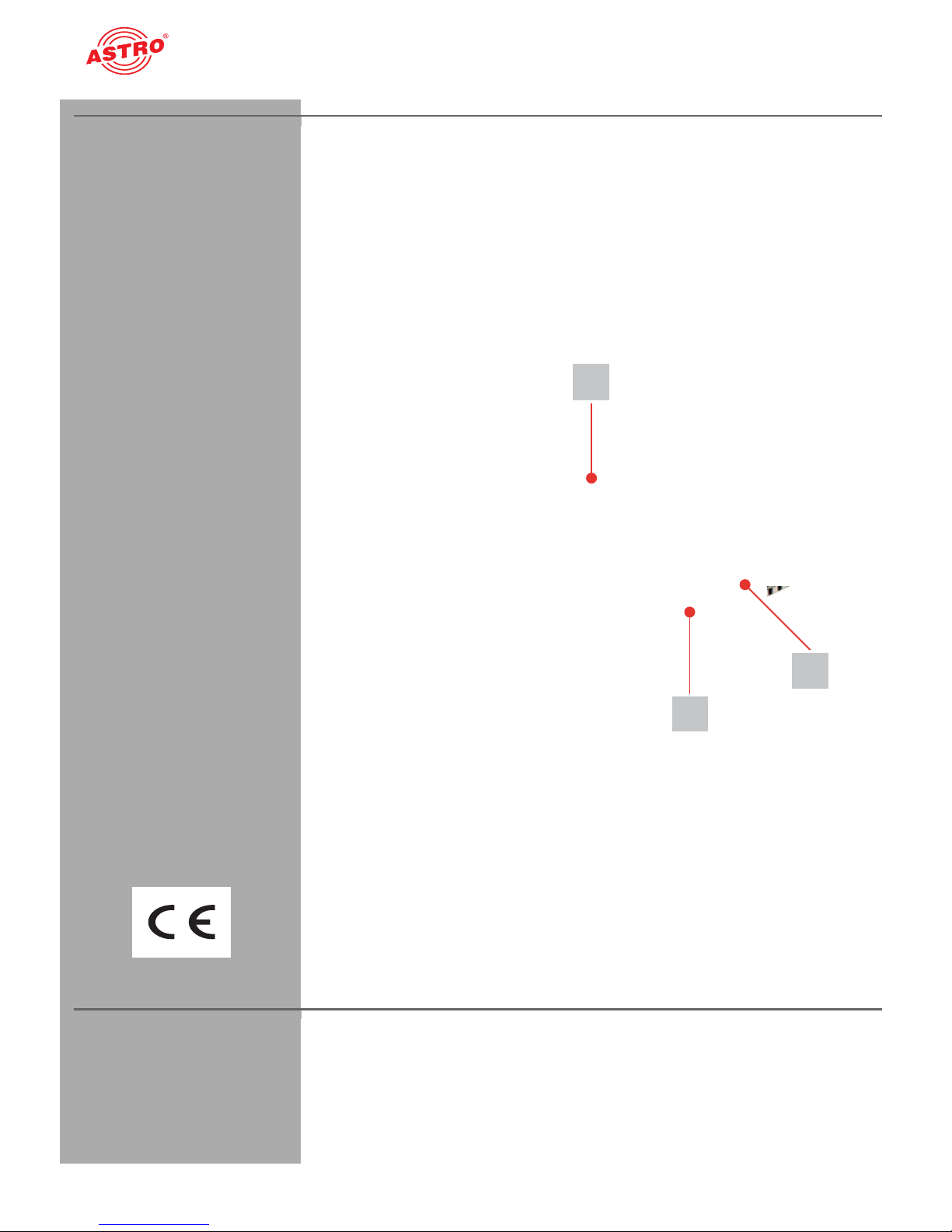
[1] Tuner A
2
[2] Tuner B
[3] Slot for output
channel filter (V 506 only)
Device description
Device description
The delivery consists of the following parts:
V 506 and X-QAM 621 CT2 plug-in cards
2 connection cables with F connectors, 450 mm & F socket-F
socket adapter
Operating manual
3
1
Figure 1: V 506 plug-in card
The V 506 and X-QAM 621 CT2 plug-in cards feature a CE marking.
This confirms that the product conforms to the relevant EG directives and adheres to the requirements specified therein.
Warranty conditions
The general terms and conditions of ASTRO Strobel GmbH apply.
You will find these in the current catalogue or on the Internet under
www.astro-kom.de.
Operating manual V 506 a. X-QAM 621 CT2 - Version 10-2014APage 2
Page 3

Description of performance
Description of performance
The V 506 and X-QAM 621 CT2 plug-in cards are used for
processing 2 digital TV programmes (DVB-C, DVB-T or DVB-T2)
from 2 independent input signal sources into 2 independent QAM
output channels in the 47 - 862 MHz frequency range. The corresponding input signal can be connected to a DVB-C, DVB-T or
DVB-T2 tuner using the HE programming software.The plug-in
cards are only designed for processing signals in the following
ASTRO base units:
V 16 using software version x.34 or higher (V 506 and X-QAM
621 CT2)
X-8 twin using software version x.34 or higher (X-QAM 621
CT2 only)
The plug-in cards are supported by the HE programming software,
version 6.5 and higher.
The V 506 and X-QAM 621 CT2 plug-in cards feature the following
performance characteristics:
Any transport current multiplex can be used between the 2
SAT inputs and the output channels
The V 506 plug-in card also features a slot for an output
channel filter
The output level of th e ou tp ut channels is adjusted using the
HE programming software
Ensure you use the card correctly by reading the following safety
and operating instructions attentively.
Operating manual V 506 a. X-QAM 621 CT2 - Version 10-2014A
Page 3
Page 4

Disposal
Disposal
All of our packaging material (cardboard boxes, inserts, plastic film
and bags) is completely recyclable. Electronic devices must not be
disposed of with household waste, but rather – according to DIRECTIVE 2002/96/EC OF THE EUROPEAN PARLIAMENT AND OF
THE COUNCIL from January 27, 2003, on waste electrical and
electronic equipment – must be properly disposed of. When it is no
longer in use, please bring the device for disposal to one of the
public collection points for this purpose.
ASTRO Strobel is a member of the Elektro system solution for the
disposal of packaging materials. Our contract number is 80395.
Important!
Before using the device, read this operating manually carefully and
store it for future reference.
To avoid danger as far as possible, you must adhere to the
following:
The device may only be installed and operated by qualified
persons (in accordance with EN 60065) or by persons who
have been instructed by qualified persons. Maintenance work
may only be carried out by qualified service personnel.
The danger and safety instructions contained in the operating
manual of the basic device and also the relevant safety regulations according to DIN VDE 0701-1 and 0701-2 must be
adhered to.
If a mixture of different signal converters is connected to the
basic device, you must note the maximum power output of the
base unit. If necessary, contact the ASTRO customer service
to clarify whether the required connections to the base unit are
permitted.
HINWEIS: The plug-in cards may only be operated with
the ASTRO base units listed in the “Description of Performance” section!
Operating manual V 506 a. X-QAM 621 CT2 - Version 10-2014APage 4
Page 5
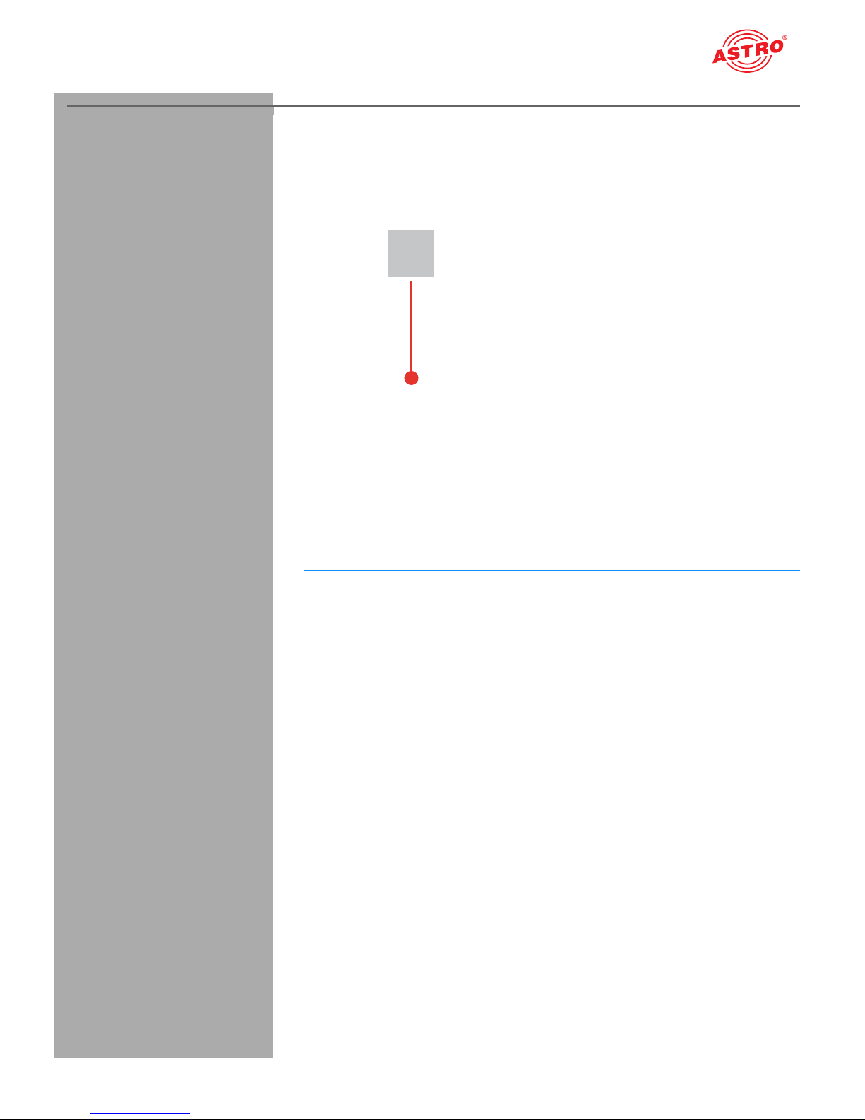
Installing the channel filter
AUFGABE
3
[3] Channel filter slot
Installing the channel filter
V 506 only: Inserting the output channel filter
Figure 4: CI module
The V 506 plug-in card features a slot to allow optional installation
of selected output channel filters of type V-KF to maintain the outstanding output parameters. They are available as an accessory.
1. Insert the channel filter into the slot provided for this purpose
(see figure 4). The filter can be activated using the HE
programming software (see section “Programming using the
HE programming software”).
RGEBNIS:
E
The plug-in card in now ready for installation and can be connected.
Operating manual V 506 a. X-QAM 621 CT2 - Version 10-2014A
Page 5
Page 6

[1] Tuner A
AUFGABE
[2] Tuner B
Connecting the plug-in card
Connecting the plug-in card
Connect both tuners A and B with the DVB-T/T2/C signal
Figure 5: Connecting tuner with DVB-T/T2/C signal
1. Screw the respective F connector at the end of the cable onto
the sockets [1] (tuner A) and [2] (tuner B).
E
RGEBNIS:
The plug-in card is now connected and can be installed in the base
unit. Installation instructions can be found in the operating manual
for the respective base unit.
Programming using the HE programming software
Activating the V 506 and X-QAM 621 CT2 in the HE programming
software
Once you have installed the plug-in card in the base unit, you can
start programming. This section tells you how to do this using the
HE programming software. You will find information on how to use
this software in the operating manual for the programming software.
Start by checking whether the card appears in the planning screen
of the base unit. To do this, select the menu Planning - display
base unit. You will now see the planning screen (see figure 6, below).
Operating manual V 506 a. X-QAM 621 CT2 - Version 10-2014APage 6
Page 7

Programming using the HE programming software
Figure 6: Planning screen for the basic unit
If it is not possible to select the plug-in card on the planning screen
of the HE programming software, select the menu Options -
card types used (see figure 7, below) and check the settings
here.
Operating manual V 506 a. X-QAM 621 CT2 - Version 10-2014A
Page 7
Page 8

Programming using the HE programming software
Figure 7: Activating the plug-in card on the “Card types used” screen.
The checkbox assigned to the card must be marked with a tick (see
above). If this is not the case, click on the checkbox to activate the
card.
RGEBNIS:
E
The plug-in card is now activated. When you click on the Read button in the planning screen (see left), the V 506 or X-QAM 621 CT2
plug-in card appears on the slot used.
Defining the input parameters
In order to define the HF input parameters, you must start by having
the detailed settings for the card displayed. To do so, click on the
Details button assigned to the card in the planning screen (see
left).
Operating manual V 506 a. X-QAM 621 CT2 - Version 10-2014APage 8
Page 9

Programming using the HE programming software
The Detailed settings screen will now appear (figure 8):
Figure 8: Input parameters
You can define the parameters for the two channels, A and B, using
the Input parameters tab. To activate input A or B, click on the
corresponding Frontend active checkbox.
In the left area of the Input Parameter tab, you can enter a
name for the program packet in the Program packet input field.
Under this, the transport stream and ON IDs are displayed for the
receiving transponder.
You can connect the two signal inputs of the plug-in card to a
DVB-C, DVB-T or DVB-T2 tuner. Select the desired tuner from the
Tuner Mode drop-down menu. The remaining input parameters
change depending on the selection you make here.
Operating manual V 506 a. X-QAM 621 CT2 - Version 10-2014A
Page 9
Page 10

Programming using the HE programming software
AUFGABE
Configuring the DVB-C tuner
Figure 9: Input parameters for the DVB-C tuner
1. Select the “DVB-C” entry from the Tuner Mode drop-down
menu.
2. Select the desired channel or the special channel from the
Channel drop-down menu.
3. Alternatively, you can freely select the channel by entering the
desired frequency in the Frequency input field.
4. The symbol rate and the modulation are set automatically.
E
RGEBNIS:
The input parameters are now defined and you can check the signal
quality (see following section “Checking the input signal quality”).
Operating manual V 506 a. X-QAM 621 CT2 - Version 10-2014APage 10
Page 11

Programming using the HE programming software
AUFGABE
Configuring the DVB-T tuner
Figure 10: Input parameters for the DVB-T tuner
1. Select the “DVB-T” entry from the Tuner Mode drop-down
menu.
2. Select the desired channel or the special channel from the
Channel drop-down menu.
3. Enter the desired frequency in the Frequency input field.
4. Select the desired bandwidth (6, 7 or 8 MHz) from the
Bandwidth drop-down menu.
5. The FFT mode and the guard interval are set automatically.
6. You can optionally activate a 5 V remote power supply for a
connected DVB-T antenna by clicking on the Remote supply
power (5 V) checkbox.
ERGEBNIS:
The input parameters are now defined and you can check the signal
quality (see following section “Checking the input signal quality”).
Operating manual V 506 a. X-QAM 621 CT2 - Version 10-2014A
Page 11
Page 12

Programming using the HE programming software
AUFGABE
Configuring the DVB-T2 tuner
Figure 9: Input parameters for the DVB-T2 tuner
1. Select the “DVB-T” entry from the Tuner Mode drop-down
menu.
2. Select the desired channel or the special channel from the
Channel drop-down menu.
3. Enter the desired frequency in the Frequency input field.
4. Select the desired bandwidth (6, 7 or 8 MHz) from the
Bandwidth drop-down menu.
5. You can optionally activate a 5 V remote power supply for a
connected DVB-T antenna by clicking on the Remote supply
power (5 V) checkbox.
E
RGEBNIS:
The input parameters are now defined and you can check the signal
quality (see following section “Checking the input signal quality”).
Checking the input signal quality
The V 506 and X-QAM 621 CT2 plug-in cards feature a test function
for identifying the input signal quality. This gives you the opportunity
to carry out a quick check of the quality of the input signal being fed
to the tuner.
Proceed as follows to identify the quality of the input signal:
Operating manual V 506 a. X-QAM 621 CT2 - Version 10-2014APage 12
Page 13

Programming using the HE programming software
AUFGABE
1. In the Detailed settings screen, click on the Check
signal quality button to open the Signal quality
window (see left).
2. You can now check the quality of the available signal. Click on
Stop measurement to complete the test.
ERGEBNIS:
The signal quality has now been checked.
Defining the output parameters
You define the output channels for the V 506 and X-QAM 621 CT2
in the planning screen; these are the channels which are used to
supply the cable with the programmes sourced from the DVB-S2
bouquet (see left).
Operating manual V 506 a. X-QAM 621 CT2 - Version 10-2014A
Figure 9: Output parameters
Click on the Details button in the planning screen to open the
Detailed settings screen. Here you can define the parameters
for the two channels, A and B, using the Output parameters tab.
Page 13
Page 14

Programming using the HE programming software
AUFGABE
1. You can activate or deactivate the channel selected using the
Output parameters tab by clicking or un-clicking the
respective active checkbox.
2. The Output channel and the Output frequency are set
automatically.
3. Select one of the settings QPSK, 16 QAM, 32 QAM, 64
QAM, 128 QAM, 256 QAM from the Modulation drop-down
menu.
4. Select the desired value from the Channel grid drop-down
menu. The options available are 2 MHz,
4 MHz, 6 MHz, 8 MHz.
5. Select a suitable value from the Symbol rate drop-down
menu. The options available are 1.725 Ms/s,
3.45 Ms/s, 5.175 Ms/s, 6.9 Ms/s.
6. For the Spectrum parameter, you can select either the
norm (normal) or inv (inverted) checkbox.
7. When the V 506 plug-in card is used, there is an additional
option of activating an output channel filter for output channel
A1, if this has been connected to the card. Activate the channel
filter by selecting the option Yes from the Channel filter
drop-down menu.
8. You can copy the changes to the configuration onto the plug-in
card by clicking on the Program card button at the top right
of the Detailed settings screen (see left).
ERGEBNIS:
The output parameters have now been set.
Setting the output level
In order to set the output level, you must start by clicking on the
Level button in the Output parameters area of the Detailed
settings screen.
Operating manual V 506 a. X-QAM 621 CT2 - Version 10-2014APage 14
Page 15

Programming using the HE programming software
AUFGABE
The Adjustment screen now appears (see figure 10).
Figure 10: Setting the output level
This is how you set the output level for channels A and B:
1. Select the desired output from the drop-down menus for output
channels A and B. You can enter values between 0 dB and
15.5 dB.
2. You now click on the Parameter write button to save the
values entered.
3. You can copy the changes to the configuration onto the plug-in
card by clicking on the Program card button at the top right
of the Detailed settings screen (see left).
E
RGEBNIS:
The output levels have now been set.
SI/PSI configuration
Click on the Details button in the planning screen to open the
Detailed settings screen. Here on the SI/PSI
Configuration tab you can define the parameters for the two
channels, A and B (see figure 11 below).
Operating manual V 506 a. X-QAM 621 CT2 - Version 10-2014A
Page 15
Page 16

Programming using the HE programming software
AUFGABE
The display for the Channel A and Channel B tabs is identical.
Figure 11: SI/PSI configuration
This is how you define the SI/PSI parameters:
1. Activate the CAT processing checkbox if you want to
process an operator ID. Now enter a hexadecimal value in the
CA_system_ID and Operator_ID input fields.
2. You can set up to four PID Remapping filters. Click on the Add
button to open the input screen for a PID (see left) and enter a
hexadecimal value in the input field. Afterwards, click on the OK
button. If you want to delete a value previously entered, click
on the Delete button.
3. You can copy the changes to the configuration onto the plug-in
card by clicking on the Program card button at the top right
of the Detailed settings screen (see left).
ERGEBNIS:
The SI/PSI configuration is now complete.
Operating manual V 506 a. X-QAM 621 CT2 - Version 10-2014APage 16
Page 17

Troubleshooting
Troubleshooting
If the device is not functioning correctly, please perform the
following checks:
Check whether the plug contacts of the card are connected to
the connectors in the base unit as described in the section
“Installing the plug-in card”.
Check whether the coaxial cables are connected correctly,
and that there are no breaks or short circuits in the connectors.
If the problem cannot be resolved, please contact the ASTRO
customer service.
Maintenance and repair
If all the instructions in this manual have been followed, and if the
device is being operated correctly, no special maintenance is
required.
HINWEIS: In the event of repairs, DIN VDE regulations
0701 - 0702, where applicable, must be adhered to, and these
are secondary to the relevant data specifications in DIN EN
60065. You must disconnect the power plug before opening
the basic device!
Operating manual V 506 a. X-QAM 621 CT2 - Version 10-2014A
Page 17
Page 18

Technical data
Technical data
Type V 506 X- CT2 QAM 621
Order number 380 516 330 603
EAN-Code
4026187161415 40261871003524
DVB-C demodulator
Input data rate [Mbaud] 0,5 - 7
Modulation modes (accord. DVB-standard)
QPSK, QAM16, QAM32, QAM64, QAM128, QAM256
DVB-T and DVB-T2 demodulator
Modulation DVB-T: 4-, 16-, 64-QAM DVB-T2: 4-, 16-, 64-QAM, 256-QAM
Guardinterval
FEC
FFT-Mode
Bandwidth
Remote voltage supply
DVB-T: 1/4; 1/8; 1/16; 1/32 DVB-T2: 1/4; 5/32; 1/8; 5/64; 1/16;
1/32; 1/64; 1/128
DVB-T: 1/2; 2/3; 3/4; 5/6; 7/8 DVB-T2: 1/2; 3/5; 2/3, 3/4; 4/5; 5/6
DVB-T: 2k, 8k DVB-T2: 1k, 2k, 4k, 8k, 16k, 32k
[MHz] DVB-T: 6; 7; 8 DVB-T2: 5; 6; 7; 8
5, typ. 100 mA, schaltbar
TS editing
Data rate adjustment
PCR-correction
NIT-handling
PID-remapping
Operator-ID
RF output
Channel selective output filters pluggable -
Connectors [Ω] IEC-jack, 75
Channel assignment
MER (Equalizer, 64 QAM)
Frequency range
Output level
Channel filter
[dB] typ. ≥ 44
[MHz] 47 - 862 (K2 - K69) adjustable in 0,1-MHz-steps
[dBμV] 84…96, adjustable
- optionally available
Common data
Power consumption [W] 8,3
Ambient temperature
[°C] 0...+45
Operating manual V 506 a. X-QAM 621 CT2 - Version 10-2014APage 18
1 x 2
Page 19

Technical data
Operating manual V 506 a. X-QAM 621 CT2 - Version 10-2014A
Page 19
Page 20

© 2014 ASTRO
Modifications to content reserved.
Change service and copyright:
This documentation contains in formation protected by copyright. It may not be
photocopied, reproduced, translated or saved on data carriers, in part or in full,
without the prior permission of the ASTRO company.
This manual created by:
ASTRO Strobel Kommunikationssysteme GmbH
Olefant 1-3, D-51427 Bergisch Gladbach (Bensberg)
Tel.: 02204/405-0, Fax: 02204/405-10
E-mail: kontakt@astro.kom.de
Internet: www.astro-kom.de
Due care was taken to ensure the a ccuracy of all the information contained in
this documentation.
The ASTRO company cannot be made liable for any damage that occurs in connection with the use of this manual.
Operating manual V 506 a. X-QAM 621 CT2 - Version 10-2014A
82 240 400 01EN
 Loading...