

Page 1

Version 07-2009A
Page 2
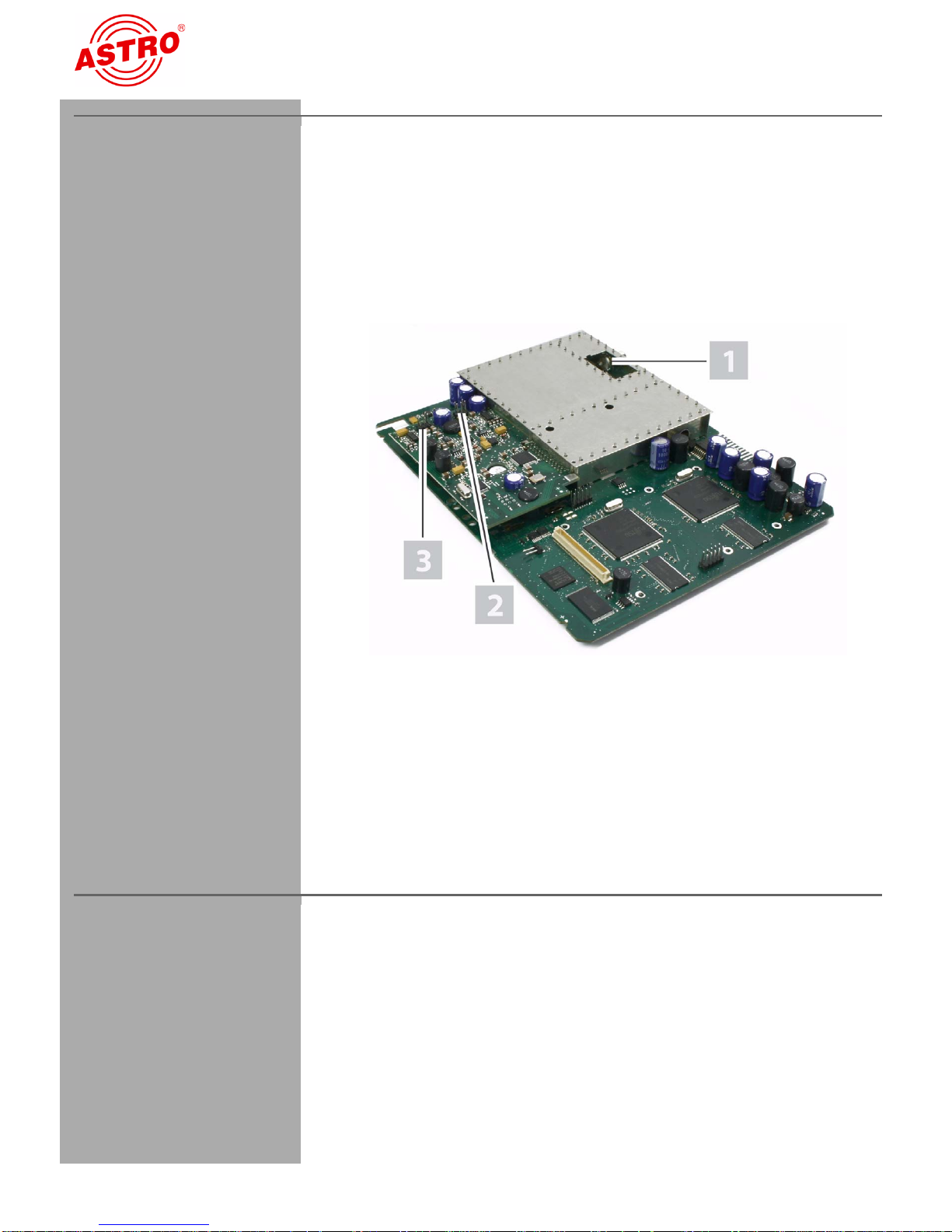
[1] Slot for output channel filter
[2] Input A
[3] Input B
Device specification
Device specification
The product includes the following parts:
V 112 plug-in card
2 AV twin adapters, 300 mm
Operating instructions
C
Figure 1: V 112 plug-in card
The V 112 plug-in card is labelled with a CE mark. This confirms that
the product complies with the relevant EC directives and satisfies
the requirements specified therein.
Warranty conditions
The general terms and conditions of ASTRO Strobel GmbH apply.
These terms are listed in the latest catalogue and also on the
Internet at address "www.astro-kom.de".
Operating Instructions V 112 - Version 07-2009APage 2
Page 3

Technical specification
Technical specification
The V 112 plug-in card is used for modulating signals from two
audio/video sources into standards-compliant TV signals in the
frequency range 47 to 862 MHz (K2 - K69). It has a common output
converter, i.e. two A/V signals can be processed into two adjacent
VHF or UHF channels of equal channel spacing. Each output
channel can be enabled/disabled independently of the other. This
plug-in card is intended solely for signal processing applications in
the following ASTRO base units:
V 16, software version x.29 and above
Read the following safety advice and operating instructions carefully to ensure you use the card properly.
The V 112 plug-in card has the following technical features:
user-selectable input signal and user-selectable output chan-
nels (can be set in the frequency range 47 - 862 MHz)
the output levels of each plug-in card can be adjusted electro-
nically to the same level using the KC3 external programming
unit or the HE programming software
the input level can be adjusted using the HE programming
software
electronic level adjustment for the output signal
excellent signal quality even after combining thanks to
channel-selective output filters (optional, please see the
"Technical Data" section); the card type and output channel
must be specified when ordering
HINWEIS: The video signals that you input to the card
must comply with the FBAS standard (PAL/CCIR 405-1) and
have a level of 1 Vss. It is essential that you ensure that input
signals lie as close as possible to this level, because although the
input level can be adjusted, there is no automatic level control.
Operating Instructions V 112 - Version 07-200 9A
You should also check when you first put the card into use that
all the channels have the same output level, and if necessary
adjust the level to match other installed equipment.
Page 3
Page 4
C
Disposal
Disposal
All of our packaging materials (cardboard, packing notes, plastic
films and bags) are fully recyclable. Electronic equipment is not
household waste, but must be disposed of properly, in accordance
with the Waste Electrical and Electronic Equipment DIRECTIVE
2002/96/EC OF THE EUROPEAN COUNCIL AND PARLIAMENT
of 27 January 2003. At the end of its service life, please take this unit
to the designated official collection points for disposal.
ASTRO Strobel is a member of „Systemlösung Elektro“ for the
disposal of packaging materials. Our contract number is 80395.5.
Important information!
Read these operating instructions carefully before using the unit,
and keep them for future use.
Follow the instructions be l o w to en s u re best possible protection
from immediate danger:
The unit must only be installed and operated by experts (as
specified in EN 60065) or by persons who have been
instructed by experts. Servicing must only be performed by
qualified service personnel.
The hazard and safety information given in the operating
instructions for the base unit, and the relevant safety regulations specified in DIN VDE 0701-1 and 0701-2, must be
observed.
When populating the base unit with different signal converters,
make sure they comply with the maximum power dissipation of
the base unit. If in doubt, please contact ASTRO Customer
Services to check whether the cards you wish to fit are suitable
for the base unit.
HINWEIS: The plug-in cards must only be operated in the
ASTRO base units listed in the "Technical specification"
section.
Operating Instructions V 112 - Version 07-2009APage 4
Page 5

Connecting the plug-in card
AUFGABE
[1] Input B
[2] Input A
[3] 15-pin D-sub connector
Connecting the plug-in card
Connecting the card
Follow the steps below to connect the card:
Figure 2: Cable connections
1. Plug each ribbon-cable connector onto the respective input of
the plug-in card (see Figure 2, above).
RGEBNIS:
E
The module is now connected and can be installed.
Operating Instructions V 112 - Version 07-200 9A
Page 5
Page 6
Fitting the plug-in card
AUFGABE
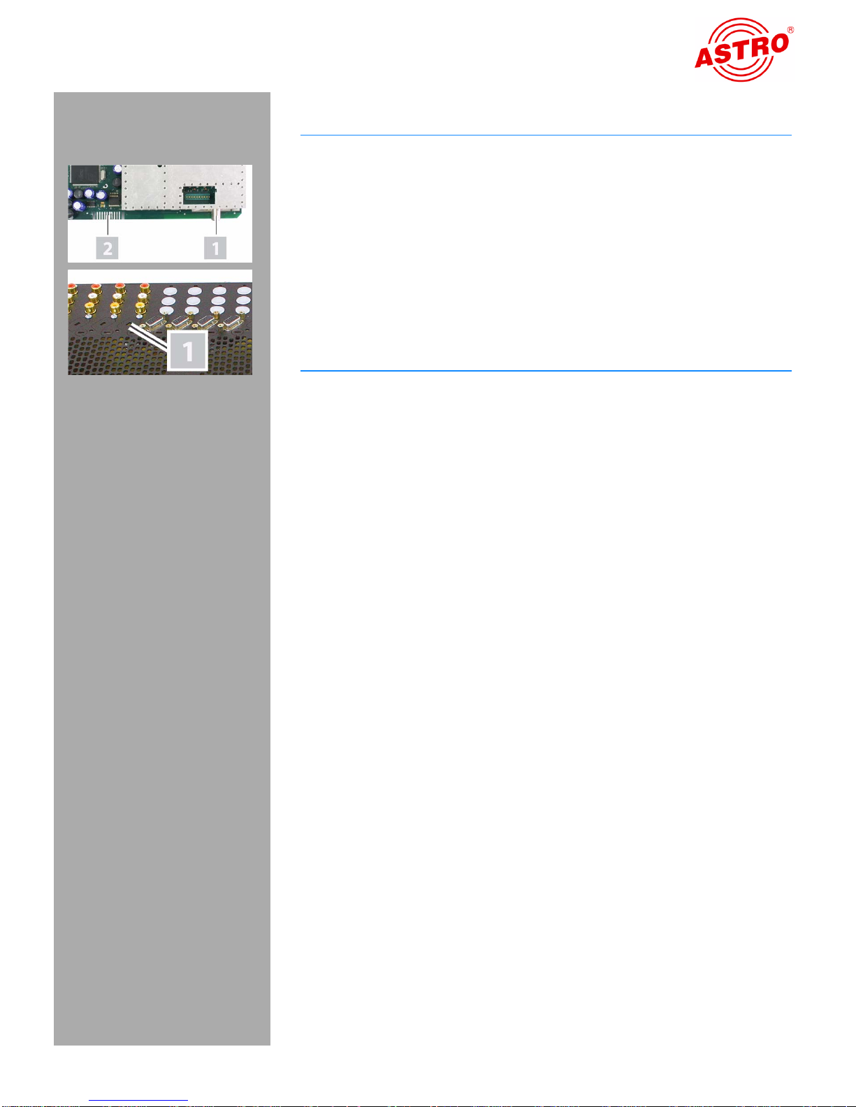
Fitting an output channel filter
In order to improve the signal-to-noise ratio, you have the option to
fit a selective output channel filter of type V-KF.. to the two outputs
of the V 112 (see "Technical Data" section).
Follow the steps below to fit the output channel filter in the card:
1. Plug a V-KF.. type filter into the slot provided for it on the top of
the card. Make sure that the filter is facing the direction shown
in the figure on the left.
RGEBNIS: You have now installed the output channel filter.
E
You need to use the HE programming software or the KC3 programming unit to enable the output channel filter. (Please see the sections "Programming with the HE programming software" and
"Programming with the KC3").
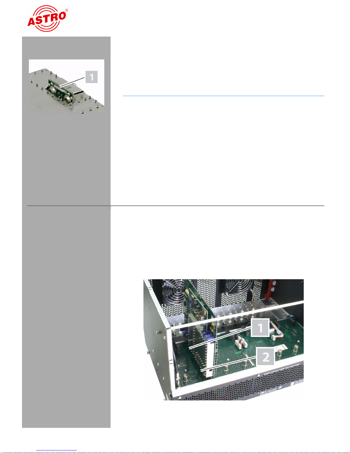
[1] Contact strip connector
[2] IEC male connector
Fitting the plug-in card
VORBEREITUNG:
You need to open the base unit before you can insert the plug-in
card. The operating instructions for the base unit describe how to
open the base unit. Once you have removed the case cover from
the base unit, you can start fitting the plug-in card.
Figure 4 shows the plug-in card once it is fitted.
Figure 4: Plug-in card fitted in base unit
Operating Instructions V 112 - Version 07-2009APage 6
Page 7
Fitting the plug-in card
AUFGABE
Follow the steps below to fit the plug-in card in the base unit:
1. Plug the IEC connector [1] and the contact strip connector [2]
(see left) into one of the slots in the base unit, as shown in
Figure 4. Each mounting slot for a plug-in card in the base unit
comprises the mating connectors to fit those on the card (i.e.
an IEC socket and a contact strip socket).
2. Remove one of the pre-punched cutouts made in the base unit
case, which are designed to take a D-sub connector socket [1]
(see lower photo on left). Insert the socket connected to the
cable in the hole, and screw the socket onto the case.
ERGEBNIS:
The plug-in card is now fitted and can be programmed.
Operating Instructions V 112 - Version 07-200 9A
Page 7
Page 8
Programming with the HE programming software
Programming with the HE programming software
Activating the V 112 in the HE programming software
Once you have fitted the V 112 plug-in card in the base unit, you can
start programming it. This section explains how you can do this
using the HE programming software. Please refer to the user manual for the programming software for general instructions on how to
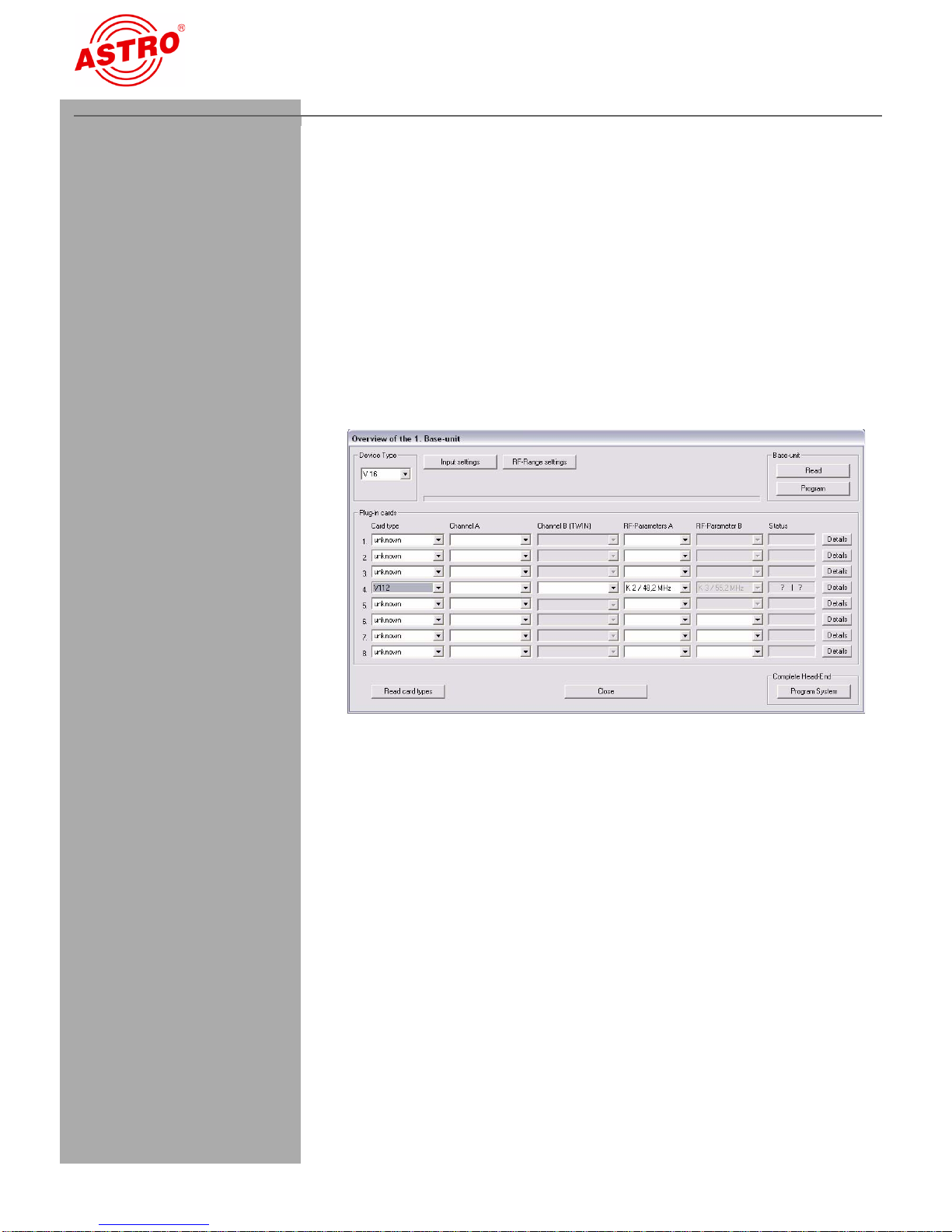
use this software. First check whether the card is displayed in the
Overview of the base unit. To do this, select the menu Design –
Displays base unit. The Overview of the base unit now opens
(see Figure 5, below).
Figure 5: Overview of the base unit
If the plug-in card is not available for selection in the base unit overwiew of the HE programming software, open the menu Options -
Favoured plug-in cards (see Figure 6, below).
Operating Instructions V 112 - Version 07-2009APage 8
Page 9

Programming with the HE programming software
Review the settings in this window:
Figure 6: Activating the plug-in card in the "Favoured plug-in cards"
window
The checkbox belonging to the card must contain a check mark
(see top left). If this is not the case, click on the checkbox to activate
the card.
ERGEBNIS:
The plug-in card is now activated. If you click on the Read button
(see left) in the Overview, the V 112 plug-in card is now shown in
the slot being used..
Specifying the input parameters and baseband parameters
In order to be able to specify the input parameters and baseband
parameters, you first need to open the detailed settings for the card.
To do this, in the Overview, click on the Details button belonging to the card (see left).
Operating Instructions V 112 - Version 07-200 9A
Page 9
Page 10
Programming with the HE programming software
AUFGABE
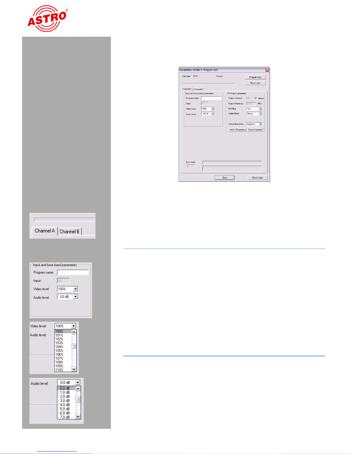
The window for the Parameters of the plug-in card now
opens (Figure 7):
Figure 7: Input parameters
You can specify the input parameters for both channels A and B in
this window. To do this, select the channel you currently require by
clicking on the relevant tab (see left).
1. In the Input and baseband parameters area (see left),
enter a program or package name (20 characters maximum) in
the relevant input field. The name you enter here is displayed
both in the Overview of the base unit and in the
frequency/channel overview.
2. To adjust the input signal you can set the video level between
80% and 150% from a drop-down list (see left). The default
value is 100% (no adjustment).
3. You can set the audio level between +6 dB and -20 dB (see
lower left). The default value is 0 dB.
E
RGEBNIS:
You have now specified the input parameters and baseband parameters.
Operating Instructions V 112 - Version 07-2009APage 10
Page 11

Programming with the HE programming software
AUFGABE
Specifying the output parameters
The user is able to select the output parameters for the two output
channels of the V 112. In the Overview, specify the parameters for
output channel A in the RF parameters A input field and for output channel B in the RF parameters B input field (see left).
1. In the Overview, click on the Details button (see left) to
open the window for the Parameters of the plug-in
card. You can make all the settings required for operation in
this window.
2. In the Output parameters area you can enable or disable
the selected channel by placing or removing a check mark in
the relevant checkbox.
3. If you have installed the optional output channel filter in the
V 112, you must select "Yes" from the "RF channel filter"
drop-down list.
4. Use the audio mode drop-down list to set the audio mode (see
left). You have the following options available: "Mono",
"Stereo", "Dual L (R)" and "Dual R (L)".
5. You can apply the configuration changes to the plug-in card by
clicking on the Program card button in the top right of the
Parameters of the plug-in card window (see left).
The output frequency display depends on the choice of output
channel in the Overview of the base unit. If the "free" option is chosen instead of selecting an output channel in the Overview, then the
Frequency field in the window for the Parameters of the
plug-in card is enabled and the user can enter any output frequency.
E
RGEBNIS:
You have now set the output parameters.
Operating Instructions V 112 - Version 07-200 9A
Page 11
Page 12
Programming with the HE programming software
AUFGABE
Setting the audio standard
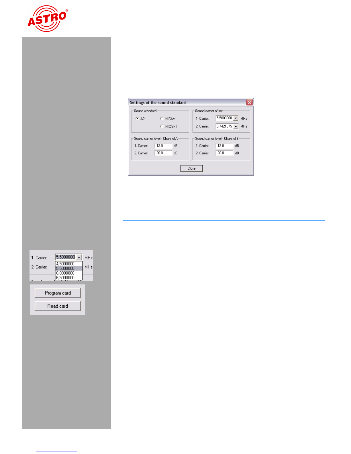
To set the audio standard, you must first click on the Sound
standard button in the Output parameters area of the window
for the Parameters of the plug-in card. The settings of the
sound standard window now opens (see Figure 8).
Figure 8: Setting the audio standard
Follow the steps below to set the audio standard:
1. Select in the top left corner one of the options "N2”, "NICAM“ or
"NICAM I” by enabling the relevant button.
2. Select the picture/audio carrier spacings for the 1st and 2nd
sound carriers from the respective drop-down list (see left).
3. Enter the sound carrier level for channels A and B in the input
fields for the 1st and 2nd sound carrier for each channel.
4. You can apply the configuration changes to the plug-in card
again by clicking on the Program card button in the top right
of the Parameters of the plug-in card window (see
left).
E
RGEBNIS:
You have now set the audio standard.
Operating Instructions V 112 - Version 07-2009APage 12
Page 13
Programming with the HE programming software
AUFGABE
Output level adjustment
You can also use the HE programming software to adjust the output
level of the V 112. In the Overview, click on the Details button
again to open the window for the Parameters of the plug-in
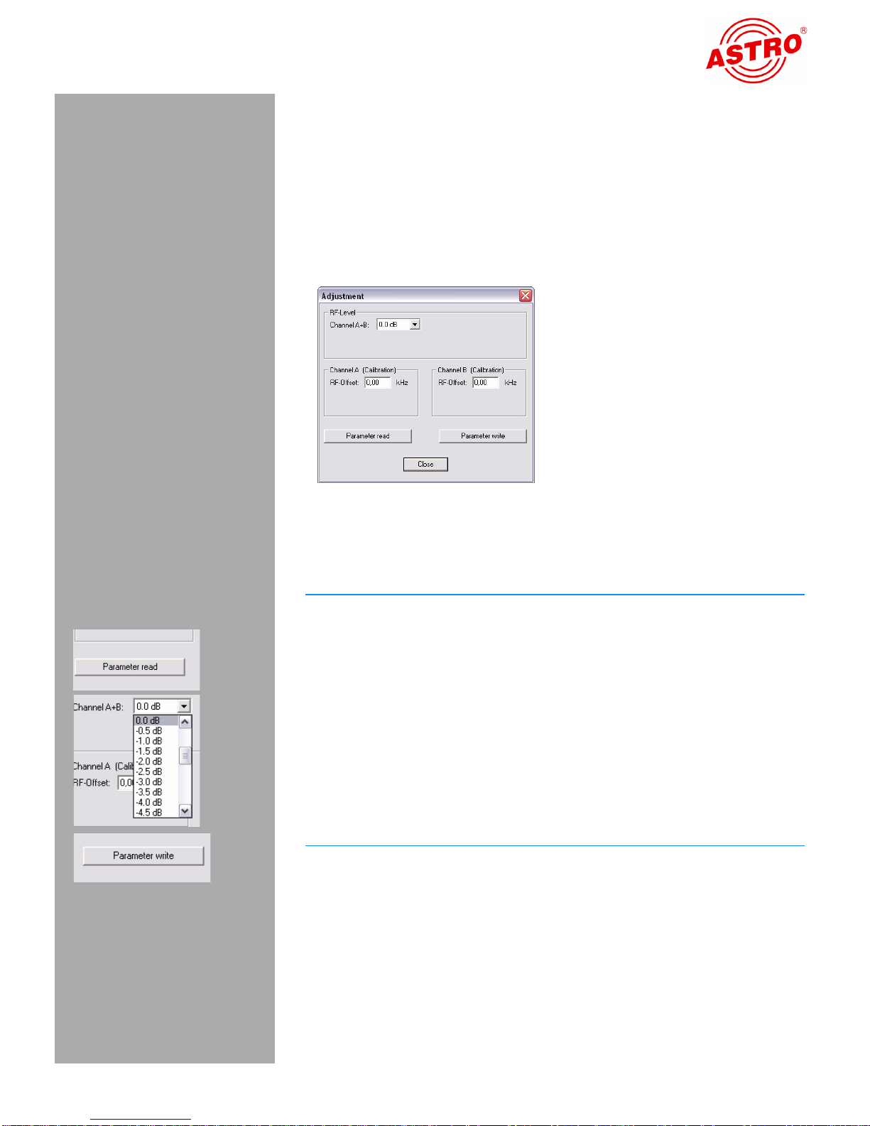
card. In this window, click on the Level / Frequency button.
The Level / Frequency window now opens (see Figure 9 below).
Figure 9: Adjusting the output level
Follow the steps below to adjust the output level for the card:
1. Click on the Parameter read button to display the values
that currently exist (see left).
2. Adjust the output level for cha nnels A and B by selecting the
value you require from the drop-down list between +5 dB and
-15.5 dB (see left).
3. Calibrate channels A and B by entering an RF offset value
(kHz) in the relevant input field for each channel.
4. Activate the values you have just entered by clicking on the
Parameter write button (bottom left).
E
RGEBNIS:
You have now adjusted the output level for the card.
Operating Instructions V 112 - Version 07-200 9A
Page 13
Page 14

Programming with the KC 3
Programming with the KC 3
Grundlagen der Bedienung
HINWEIS: The section "Quick reference guide to program-
ming with the KC3" summarizes the operating steps that you
need to follow to configure the plug-in card. The following
section starts with basic instructions on how to operate the
KC3. It then explains how to set all the parameters required for
configuration.
HINWEIS: Since it is not possible to set all the parameters
of the V 112 using the KC3 programming unit, you should
preferably program the card using the HE programming software.
If you wish to program the V 112 plug-in card using the KC3 programming unit, you must first connect the serial port of the KC3 to
the serial port socket of the base unit being used (see left).
Once you have plugged in the KC3 programming unit, the start
menu is displayed. The display shows the type of the base unit and
the software version number (see left). Please quote this version
number if you need to consult Customer Services.
If you wish to display the start menu again after entering programming steps, you will need to disconnect the KC3 from the base unit
first, then wait until the display goes blank, and then plug the connector back in.
Pressing the or cursor button takes you first into the menu for
setting the base unit parameters. In this menu, use the or cursor button to move to the line containing the parameter you wish to
set. Press the or cursor button to change specific settings for
the base unit parameters.
Pressing the Menu / Read button takes you to the menu for setting
the card-specific parameters. The following parameters can be adjusted here in the respective lines:
Line 1: card type
Line 3 / 4: output parameters
Operating Instructions V 112 - Version 07-2009APage 14
Page 15
Programming with the KC 3
AUFGABE
You can enter the parameters directly via the keypad or alter preset
parameters incrementally by pressing the and cursor buttons.
Once you have entered a parameter value, you should save it immediately by pressing the OK - Store button. The val ues are then
written to the card.
HINWEIS: Numerical values must be entered in full. You
risk losing data through power failure until settings have been
saved!
Once you have made all your settings, you can check operation at
the output of the head end.
The following section explains how to configure the plug-in card in
detail:
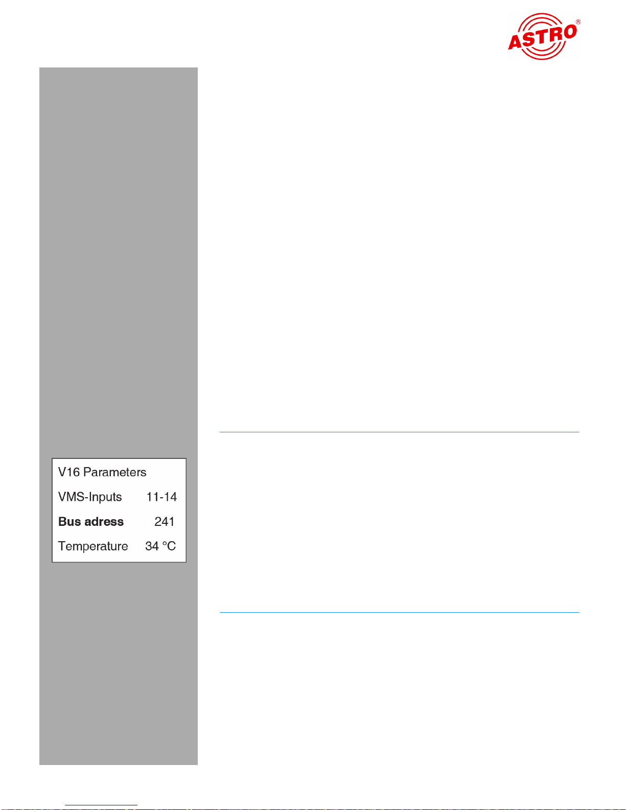
Setting the base-unit bus address
If several base units are connected together, you must make sure
that all connected base units are set to different bus addresses in
order to avoid conflicts on the ASTRO bus. The base units are delivered with the address preset to 241.
Follow the steps below to set the bus address for the base unit:
1. After plugging in the connector from the KC3, use the or
cursor button to access the menu for setting the base unit
parameters.
2. Select line 3 by pressing cursor button or until the cursor
sits in line 3.
3. The value for the bus address can lie between 001 and 020, or
equal 241. Press cursor button or until the bus address
you require is displayed (see left).
4. Press the OK / Store button to save the setting.
Operating Instructions V 112 - Version 07-200 9A
E
RGEBNIS:
You have now set the bus address of the base unit.
Page 15
Page 16

Programming with the KC 3
AUFGABE
AUFGABE
Selecting the slot
1. line 1 by pressing cursor button or until the cursor sits in
line 1.
2. Press cursor button or , until the display shows the slot and
particular channel you require (the example on the left is for slot
6, channel A).
E
RGEBNIS:
You have now selected the slot for the card and the channel you
wish to configure. Once you have made all the remaining settings
for this channel, you need to configure the other channel by repeating the entire procedure described below.
Input parameters
HINWEIS: The input parameters can only be set using the
HE programming software (see the section "Programming
with the HE programming software").
Specifying the output parameters
First set the picture carrier frequency:
1. Select line 3 by pressing cursor button or until the cursor
sits in line 3.
2. Press the Menu / Read button until you reach the input carrier
submenu (PictureCr) (see left).
3. Use the numeric keypad to enter the required frequency, or
change the displayed frequency in steps of 100 kHz by pressing the or cursor button until you reach the value you
require.
4. Press the OK / Store button to save the setting.
Operating Instructions V 112 - Version 07-2009APage 16
Page 17

Programming with the KC 3
AUFGABE
AUFGABE
HINWEIS: Instead of setting the output frequency you can
set the channel in line 4 of the display. To do this, Press the
or
cursor button to get to the fourth line. Select the channel
you require by pressing the
ERGEBNIS:
You have now set the picture carrier and can proceed to select the
audio modulation.
1. Select line 3 by pressing cursor button or until the cursor
sits in line 3
2. Press the Menu / Read button until you reach the audio
modulation submenu (AudioMod) (see left).
3. Select one of the four options ("Stereo”, "Mono”, "Dual L (R)”,
"Dual R (L)”) by pressing the or cursor button until you
reach the setting you require.
4. Press the OK / Store button to save the setting.
or cursor button.
E
RGEBNIS:
You have now set the audio modulation and can proceed to enabling / disabling the output signal.
1. Select line 3 by pressing cursor button or until the cursor
sits in line 3.
2. Press the Menu / Read button until you reach the output
signal submenu (OutpSignal) (see left).
3. Use the and cursor buttons to switch it "On“ (see left,
output enabled) or "Off“ (output disabled).
4. Press the OK / Store button to save the setting.
ERGEBNIS:
You have now enabled/disabled the output signal. You can now get
the display to show any error messages that may exist.
Operating Instructions V 112 - Version 07-200 9A
Page 17
Page 18

Programming with the KC 3
AUFGABE
AUFGABE
1. Select line 3 by pressing cursor button or until the cursor
sits in line 3.
2. Press the Menu / Read button until you reach the Errors
submenu.
3. If the card is working properly then "none” is displayed. If the
display shows any other messages , pl e a se co ntact ASTRO
Customer Services.
E
RGEBNIS:
If there is no error message you can proceed with adjusting the output level.
1. Select line 3 by pressing cursor button or until the cursor
sits in line 3.
2. Press the Menu / Read button until you reach the RF-level
submenu.
3. Use the and cursor buttons to select the required attenuation level.
4. Press the OK / Store button to save the setting.
E
RGEBNIS:
You have now set the output level and all the other output parameters. If you have installed the optional output channel filter then you
still need to enable this filter:
Operating Instructions V 112 - Version 07-2009APage 18
Page 19
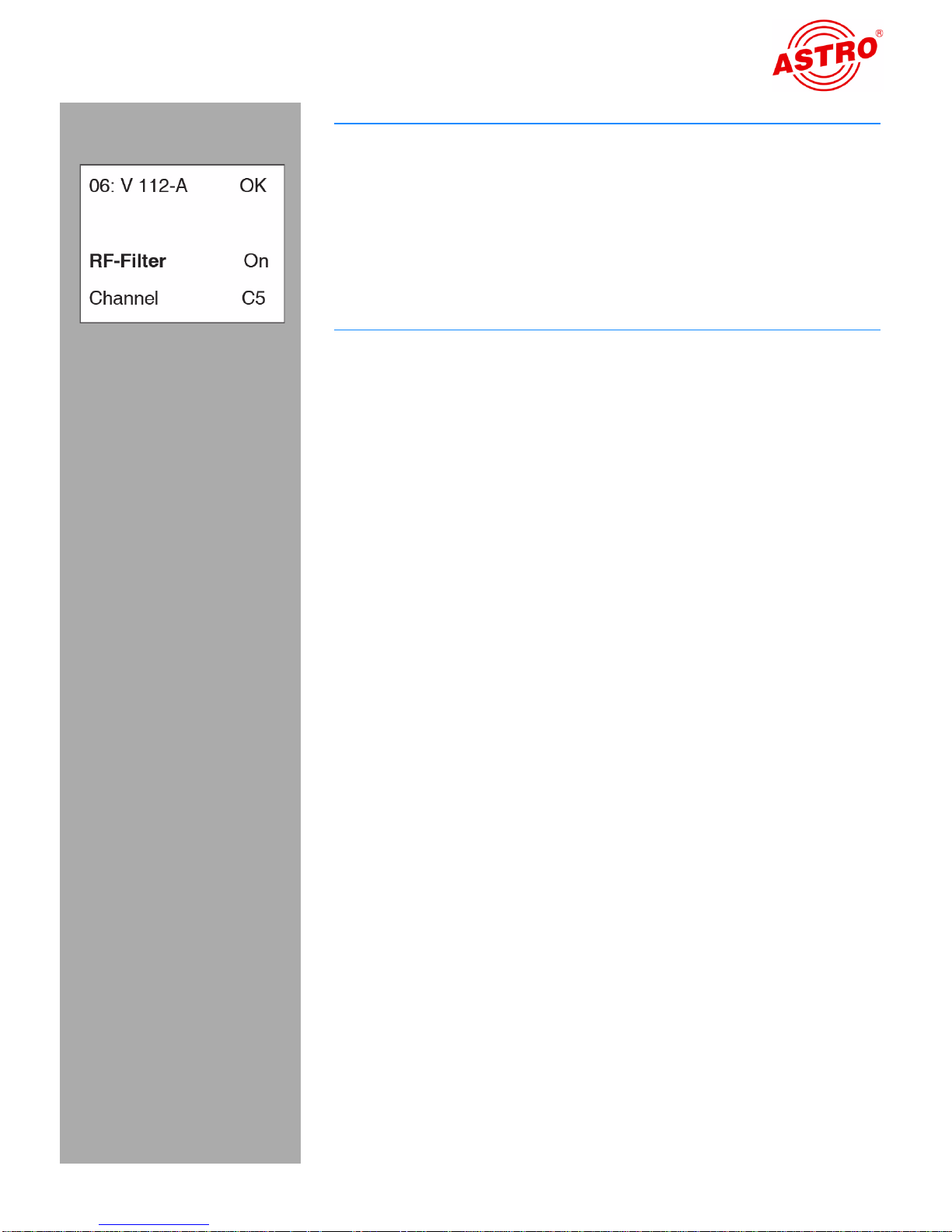
Programming with the KC 3
AUFGABE
1. Select line 3 by pressing cursor button or until the cursor
sits in line 3.
2. Press the Menu / Read button until you reach the RF filter
submenu.
3. Use the and cursor buttons to switch it "On"
4. Press the OK / Store button to save the setting.
E
RGEBNIS:
You have now enabled the output channel filter.
Operating Instructions V 112 - Version 07-200 9A
Page 19
Page 20

Quick reference guide to programming with the KC3
Quick reference guide to programming with the KC3
Operating Instructions V 112 - Version 07-2009APage 20
Page 21

Quick reference guide to programming with the KC3
Page 21Operating Instructions V 112 - Version 07-2009A
Page 22

Troubleshooting
Troubleshooting
If the unit is not working correctly, please carry out the following
checks:
Check that the plug-in contacts of the card are connected to
the sockets in the base unit, as described in the section "Fitting
the plug-in card“.
Check that the coaxial cables are connected correctly and that
the connectors have not been open-circuited or short-circuited.
If you are unable to correct the problem, please contact ASTRO
Customer Services.
Servicing and repair
Provided all the directions given in these operating instructions are
followed, and the device is used in accordance with its intended
purpose, then no special servicing is required.
HINWEIS: BIf repairs are carried out, the regulations in
standard DIN VDE 0701 - 0702 must be observed, where
applicable, and in particular the relevant requirements specified in DIN EN 60065. The mains plug must be removed
without fail before opening the base unit!
Operating Instructions V 112 - Version 07-2009APage 22
Page 23
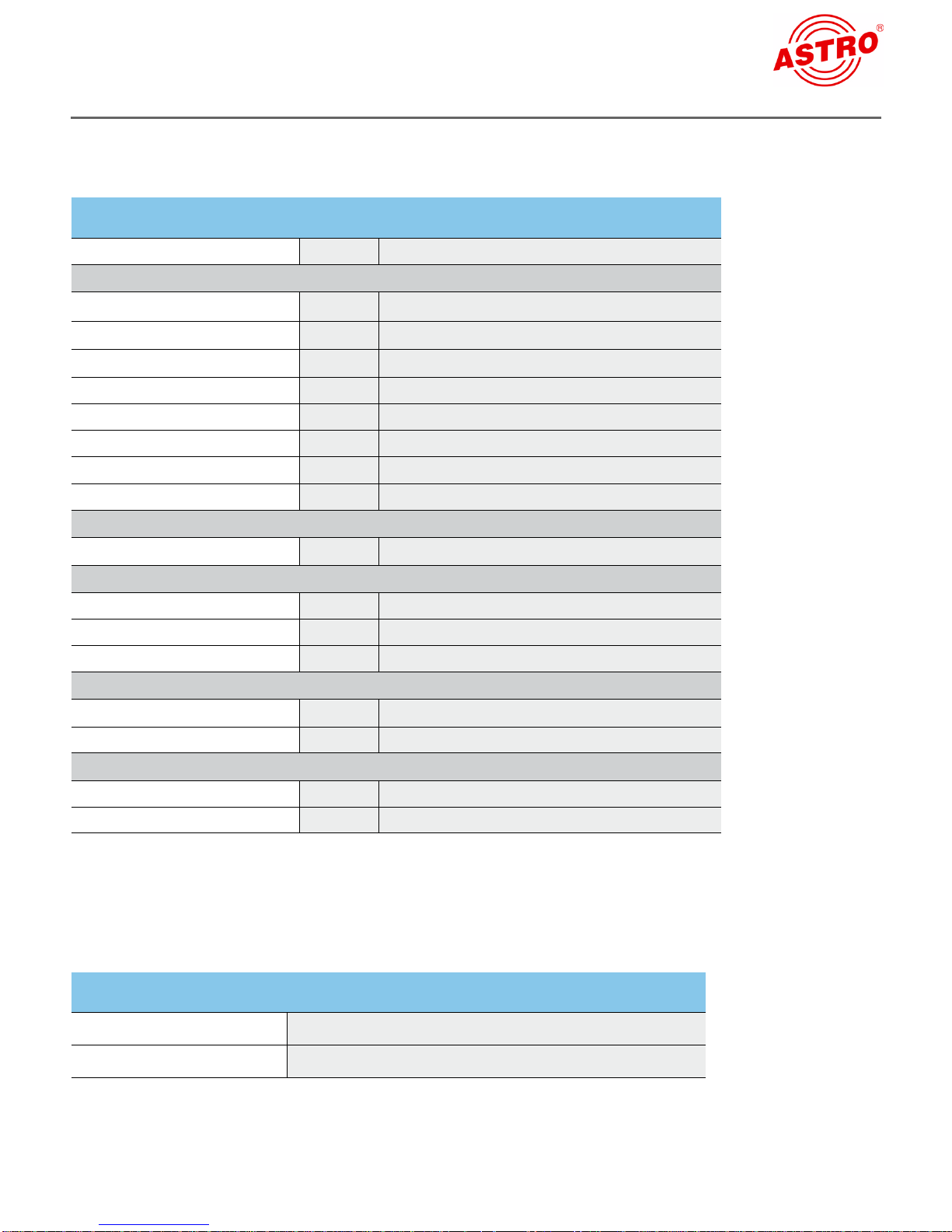
Technichal data
Type V 112
Order number 380 321
RF-Modulators
Output frequency range [MHz] 47 - 862
Technichal data
Output channels
Output level
Intermodulation distance
Return loss
Spurious frequency distance
TV standard
Video-signal to noise ratio
[dBμV] 90 - 100
[dB] typ. 60
[dB] > 10
[dB] typ. 60
PAL/SECAM, B/G/D, SECAM L, A2/NICAM
[dB] typ. 60
K2 - K69
Audio / Video
Input 15-pin SUB-D-jack (per jack 2 A/V-input signals)
Audio
Input level [V RMS] 0,5 / 600 Ω
Frequency range
Signal to noise ratio
[Hz] 40 - 15000
[dB] typ. 45
Video
Bandwidth 25 Hz - 4,8 MHz
Input level
[Vss] 1 / 75 Ω
Common Daten
Power consumption [W] 11.5
Ambient temperature
[°C] 0…+50
Selective output channel filters available (please specify output channel and card type when ordering):
Typ V-KF…
Order number 380…
Channel range in MHz
111…862
Page 23Operating Instructions V 112 - Version 07-2009A
Page 24

© 2009 ASTRO
Subject to change.
Change management and copyright:
This document contains information protected by copyright. It is prohibited to
photocopy, duplicate, translate or store on data storage media this document,
either partially or in full, without prior agreement of the ASTRO company.
These operating instructions have been written by:
ASTRO Strobel Kommunikationssysteme GmbH
Olefant 1-3, D-51427 Bergisch Gladbach (Bensberg)
Tel.: 02204/405-0, Fax: 02204/405-10
eMail: kontakt@astro.kom.de
Internet: www.astro-kom.de
All the information contained in this document has been checked in good faith.
The ASTRO company cannot be held liable for any damage or injury arising in
connection with the use of these operating instructions.
Operating Instructions V 112 - Version 07-2009A
82 287 400 07/09EN
 Loading...