

Page 1

U 911 ... 946
ACTIVE SAT DISTRIBUTION FIELD
Page 2
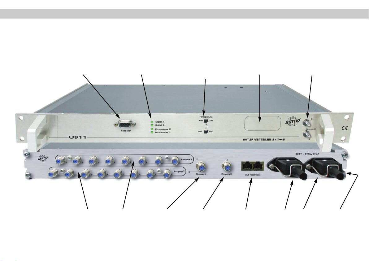
Illustrations
front view
rear view
U 911
Controller port Indicator lamps
outputs Y outputs X input Y input X Bus port Mains supply
U 911
Remote feed
ON/OFF
Labeling field Measurement points
Grounding
connections
terminal
2
Page 3
Contents 1 Safety information
Important:
Hazard warnings and safety information . . . . . . . . . . . . . . Page 3
U 911 illustration . . . . . . . . . . . . . . . . . . . . . . . . . . . . . . Page 2
1 Pictograms . . . . . . . . . . . . . . . . . . . . . . . . . . . . . . . . . . Page 3
2 Hazard warnings and safety information . . . . . . . . . . . Page 3
2.1 Installation information . . . . . . . . . . . . . . . . . . . . . . Page 3
2.2 Opening the housing . . . . . . . . . . . . . . . . . . . . . . . Page 4
2.3 Equipotential bonding / grounding . . . . . . . . . . . . . Page 4
3 Different type designations . . . . . . . . . . . . . . . . . . . . . . Page 5
4 Programming with the KC 3 . . . . . . . . . . . . . . . . . . . . . Page 5
4.1 Fundamentals / device password . . . . . . . . . . . . . Page 5
4.2 Setting the bus address . . . . . . . . . . . . . . . . . . . . . Page 6
4.3 Programming the SAT inputs . . . . . . . . . . . . . . . . . Page 6
4.4 Monitoring the remote powering / alarms . . . . . . . Page 6
5 Programming with the HE programming software . . . . Page 7
5.1 Inserting the SAT distribution field in a project . . . Page 7
5.2 Programming the SAT inputs . . . . . . . . . . . . . . . . . Page 8
6 Indicator lamps . . . . . . . . . . . . . . . . . . . . . . . . . . . . . . . Page 9
7 Technical data . . . . . . . . . . . . . . . . . . . . . . . . . . . . . . .Page 10/11
1 Pictograms and safety information
Pictograms are symbols which have a defined meaning.
You will encounter the following pictograms in these
operating and installation instructions:
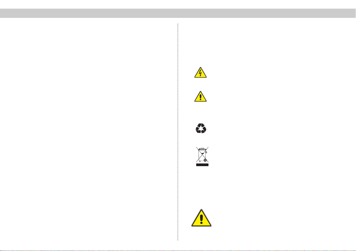
This symbol is used to warn about situations in which
there is a risk of fatal injury due to dangerous electrical
voltages or as a result of failure to comply with these
instructions.
This symbol is used to warn about various risks to
health, equipment/materials or the environment.
This symbol is used to indicate general information.
☞
Recycling symbol: all of our packaging materials (cardboard packaging, package inserts, plastic film and plastic bags) can be fully recycled.
Electronic equipment is not household waste – in accordance with directive 2002/96/EC OF THE EUROPEAN
PARLIAMENT AND THE COUNCIL of 27thJanuary 2003 on
used electrical and electronic equipment, it must be disposed
of properly. At the end of its service life, take this unit for disposal at a relevant official collection point.
2 Hazard warnings and safety information
2.1 Installation information
The device must only be installed in a dry room.
Assembly location: indoor room
3
Page 4
2 Hazard warnings and safety information 2 Hazard warnings and safety information
The device must not be exposed to splashing or dripping
water. Objects filled with a liquid must not be placed on
the device.
In the event of condensation, wait until the device is completely dry.
The permissible ambient temperature range is 0…50°C.
The equipment must only be installed in rooms in which
it is ensured that the required ambient temperature conditions are met even under fluctuating climatic conditions.
Warning: Please pay special attention to ensuring that
the ambient temperature requirements are met if the unit
is installed in a loft or attic space.
2.2 Opening the housing
Important – please note the following before opening
the device:
Disconnect the mains plug.
(Take care when working on the power supply unit. Some components may still carry a voltage after disconnection from the
mains and could cause an electrical shock if touched.)
Never perform any service repairs during a thunderstorm.
The power cord(s) must only be replaced by equivalent
genuine ASTRO replacement power cord(s).
Fuses must only be replaced with replacement fuses of
the same type and with the same ratings and melting
characteristics.
Important:
Compliance must be ensured with:
DIN VDE 0701 – parts 1 and 200, servicing
EN 50 083 – part 1, safety requirements
2.3 Equipotential bonding / grounding
The device must be properly grounded and installed in accordance with EN 50 083 – part 1.
The requirements laid out in EN 50083 – part 1 and the national
legislation relating to IT/TT power supply networks must be complied with
Operation of the device without a protective ground
connection, proper grounding of the device or equipotential bonding is not permitted.
The housing must only be opened by an authorized specialist who has been certified by the Chamber of Commerce and Industry (master workshop). The device must only
be repaired by an authorized specialist who has been certified by the Chamber of Commerce and Industry (master
workshop), or alternatively by sending it back to ASTRO
together with a detailed description of the fault.
4
Page 5

3 Type designations 4 Programming with the KC 3
3 Different type designations
Input impedance: 75 Ω Output impedance: 75 Ω
U911 R 2 x 1 in 8 with two power supply units
U912 R 2 x 1 in 8 with one power supply unit
U913 R 2 x 1 in 8 with no power supply unit
U914 R 1 x 1 in 16 with two power supply units
U915 R 1 x 1 in 16 with one power supply unit
U916 R 1 x 1 in 16 with no power supply unit
Input impedance: 50 Ω Output impedance: 50 Ω
U 921 R 2 x 1 in 8 with two power supply units
U 922 R 2 x 1 in 8 with one power supply unit
U 923 R 2 x 1 in 8 with no power supply unit
U 924 R 1 x 1 in 16 with two power supply units
U 925 R 1 x 1 in 16 with one power supply unit
U 926 R 1 x 1 in 16 with no power supply unit
Input impedance: 50 Ω Output impedance: 75 Ω
U 931 R 2 x 1 in 8 with two power supply units
U 932 R 2 x 1 in 8 with one power supply unit
U 933 R 2 x 1 in 8 with no power supply unit
U 934 R 1 x 1 in 16 with two power supply units
U 935 R 1 x 1 in 16 with one power supply unit
U 936 R 1 x 1 in 16 with no power supply unit
Input impedance: 75 Ω Output impedance: 50 Ω
U 941 R 2 x 1 in 8 with two power supply units
U 942 R 2 x 1 in 8 with one power supply unit
U 943 R 2 x 1 in 8 with no power supply unit
U 944 R 1 x 1 in 16 with two power supply units
R 1 x 1 in 16with one power supply unit
U 945
U 946 R 1 x 1 in 16 with no power supply unit
The different variants may vary slightly from the descrip-
tions provided in the operating instructions in terms of
their operation.
Other special types available on request.
4. Programming the SAT distribution field
with the KC 3
4.1 Fundamentals
After plugging in the KC 3 programming device the Start
menu will initially appear. The software version number
is displayed..
Please quote this number whenever contacting our
customer service department.
The Start menu can only be accessed again later on by
unplugging and replugging the KC 3.
After plugging in the KC 3, you can press the “Menu
Read” button first to view additional data for the device
(no. of LNC inputs, redundant power supply unit
yes/no). Here, you can use the
go to row four and access the menu for
Setting up a device password:
Use the ← or → cursor keys to activate the password
function. After pressing the “OK Store” button you will be
asked to enter the new password. If the password function is active then it will not be possible to save changes
without the password. Please contact the manufacturer
if you cannot remember your password.
↑ and ↓ cursor keys to
5
Page 6

4 Programming with the KC 3 4 Programming with the KC 3
After plugging in the KC 3, you can use the ← or → cur-
sor keys to access the menu for adjusting the parameters of the SAT distribution field.
4.2 Setting the bus address
After plugging in the KC 3, press the ← or → cursor
keys to access the menu for setting the bus address.
Then press the
of the menu, where you can use the
keys to select a bus address value between 31 and 50.
Then press “OK Store” to save the selected settings.
The message “Data saved” will appear for about 1
second.
4.3 Programming the SAT inputs
After plugging in the KC 3 and pressing the ← or → cursor key twice you will go to the menu for setting the bus
address and on to the menu for programming the X
input of the SAT distribution field. You can then use the
↑ or ↓ cursor keys to go to the second row of the “X
input” menu for
Adjusting the attenuation
with the ← or → cursor keys in increments of 0.5 dB. The
attenuation can be set to a range from 0 to 16 dB. Press
the button “OK Store” to save the changes made. The
message “Data saved” will appear for about 1 second. If
you press the button “Menu read” in the second row as
well then this will take you to the menu for
↑ or ↓ cursor keys to go to the third row
← or → cursor
The equalization can be activated or deactivated by
pressing the ← or → cursor keys. Here again you need
to press “OK Store” to save the changed settings.
4.4 Monitoring of the remote powering / alarms
The remote powering which can be activated on the front
panel of the device and can also be monitored:
↑ or ↓
Use the
input” menu, where you can change all settings for monitoring the remote powering and for the alarms which are triggered when certain values drop below their alarm thresholds. The current remote feed current is displayed here
initially. Pressing the “Menu Read” button will take you to
the activation and deactivation of the alarms, which is set
with the aid of the
Read button again and use the
adjust the lower alarm threshold in 50 mA increments (from
50 mA to 250mA). The upper alarm threshold is adjusted
in similar fashion after pressing the “Menu Read” button
(range from 100 mA to 350 mA).
The fourth row of the “X input" menu shows the current
temperature of the device.
All of the information for the “X input” menu applies analogously to the “Y input" menu.
cursor keys to go to the third row of the “X
← or →
cursor keys. Press the “Menu
← or →
cursor keys to
Activating the 7 dB slope equalization:
6
Page 7

5 Programming with the HE programming software 5 Programming with the HE programming software
5. Programming the SAT distribution field
with the HE programming software
5.1 Inserting the SAT distribution field into a project
One or more SAT distribution fields can be inserted under
“Planning → Project Data” in the HE programming software.
After entering the SAT distribution field it can be called
up in the HE programming software under “SAT-ZF predistribution”.
7
Page 8

5 Programming with the HE programming software 5 Programming with the HE programming software
5.2 Programming the SAT inputs
Any of the satellites stored in the database can be
assigned to the SAT inputs.
In addition, the 7 dB slope equalization and the monitoring of the LNC remote feed can also be activated or
deactivated via the software. Values between 100 mA
and 700 mA are available for the lower threshold, with
values between 200 mA and 800 mA available for the
upper threshold (in increments of 50 mA).
The next step is to select the polarization and the band.
The attenuation of the SAT distribution field can also be
adjusted via the HE programming software. The adjustment range is 0 to 16 dB, with increments of 0.5 dB.
8
Page 9

5 Programming with the HE programming software 6 Indicator lamps
6. Indicator lamps
The green LED on the front panel of the device indica-
tes that the power supply unit is operating without any
faults. A green LED is also used to indicate if the LNC
remote feed is activated.
If the monitoring of the LNC remote feed is activated
and the current reading moves outside the previously
specified window then this is signaled with a red LED.
The current remote feed current is displayed after the
SAT distribution field has been read out. Read it out
again to update the display.
All operating information for the X-input applies analogously to the Y-input.
9
Page 10

7 Technical data
Type U-911 U-912 U-913 U-914 U-915 U-916 U-921 U-922 U-923 U-924 U-925 U-926
Order no.
Inputs / outputs 2x 1 in 8 1x 1 in 16 2x 1 in 8 1x 1 in 16
No. of power supply units
230V / 28VA 2 1 0 2 1 0 2 1 0 2 1 0
Remote feed current [mA] 350 350 1500* 350 350 1500* 350 350 1500* 350 350 1500*
LNC feed voltage [V] 16 16 15–18 16 16 15–18 16 16 15–18 16 16 15–18
Inputs /outputs
Input frequency range [MHz] 950–2150
Nominal input level
Transmission loss [dB] 0 ±2
Level decoupling [dB] > 40
Level adjuster (0.5 dB increments) [dB] 0…-15
Slope equalization
Freq. response, insertion attenuation
in 36 MHz bandwidth [dBss]< 1
in nominal frequency range
Active return loss
Inputs/outputs [dB] ≥ 12 / ≥ 14
Output decoupling [dB] > 20
Measuring outputs (1 per level)
Nominal decoupling attenuation [dB] -10
Active return loss [dB] 15
* max. 1.5 A, depending on the feed network proportion and the internal fuses.
(F sockets)
(SMA connectors) [Ω] –– 50 / 50
[dBµV] 85
[dBss]< 2
380 192 380 212 380 213 380 214 380 215 380 216 380 221 380 222 380 223 380224 380 225 380 226
[Ω] 75 / 75 ––
[dB] 0/7 ±1
10
Page 11

7 Technical data
Type U-931 U-932 U-933 U-934 U-935 U-936 U-941 U-942 U-943 U-944 U-945 U-946
Order no.
Inputs / outputs 2x 1 in 8 1x 1 in 16 2x 1 in 8 1x 1 in 16
No. of power supply units
230V / 28VA 2 1 0 2 1 0 2 1 0 2 1 0
Remote feed current [mA] 350 350 1500* 350 350 1500* 350 350 1500* 350 350 1500*
LNC feed voltage [V] 16 16 15–18 16 16 15–18 16 16 15–18 16 16 15–18
Inputs /outputs
Input frequency range [MHz] 950–2150
Nominal input level
Transmission loss [dB] 0 ±2
Level decoupling [dB] > 40
Level adjuster (0.5 dB increments) [dB] 0…-15
Slope equalization
Freq. response, insertion attenuation
36 MHz bandwidth [dBss] < 1
in nominal frequency range
Active return loss
Inputs/outputs [dB] ≥ 12 / ≥ 14
Output decoupling [dB] > 20
Measuring outputs (1 per level)
Nominal decoupling attenuation [dB] -10
Active return loss [dB] 15
* max. 1.5 A, depending on the feed network proportion and the internal fuses.
(F sockets)
(SMA connectors) [Ω] 50 / – – / 50
[dBµV] 85
[dBss]< 2
380 231 380 232 380 233 380 234 380 235 380 236 380 241 380 242 380 243 380244 380 245 380246
[Ω] – / 75 75 / –
[dB] 0/7 ±1
11
Page 12

Kommunikationssysteme GmbH
ASTRO Strobel
Olefant 1–3
D-51427 Bergisch Gladbach (Bensberg)
Tel. 0 22 04 / 405-0
Fax 0 22 04 / 405 10
http://www.astro-kom.de
82 270400 10/ 2006 GB
 Loading...