

Page 1

Version 10-2018A
Page 2

Contents
Contents
Before starting operation of the device.......................................................................................page 03
Symbols and conventions used..................................................................................................page 03
Proper use..................................................................................................................................page 04
Target group for this manual......................................................................................................page 04
Device description .....................................................................................................................page 04
Important safety information......................................................................................................page 05
Warranty conditions...................................................................................................................page 07
Disposal.....................................................................................................................................page 07
Description of performance .......................................................................................................page 07
Connecting and installing the module .......................................................................................page 07
Quick start – starting operation of the U 158.............................................................................page 09
“Status” menu............................................................................................................................page 16
“Main” menu ..............................................................................................................................page 22
“Test generator” menu...............................................................................................................page 24
“IP channel” menu .....................................................................................................................page 26
“IP RX” menu.............................................................................................................................page 27
“RF” menu .................................................................................................................................page 29
“RF 1.X” and “RF 2.X” menu .....................................................................................................page 32
“TS processing” menu ...............................................................................................................page 34
“NIT” menu ................................................................................................................................page 37
“LCN” menu...............................................................................................................................page 39
“SSL settings” menu..................................................................................................................page 40
“User settings” menu .................................................................................................................page 42
“TS analyzer” menu...................................................................................................................page 44
“Licensing” menu.......................................................................................................................page 45
“Update/config” menu................................................................................................................page 46
“System log” menu ....................................................................................................................page 49
“Alarm severities” menu ............................................................................................................page 51
“Active alarms” menu ................................................................................................................page 52
“Statistics” menu........................................................................................................................page 53
“Network” menu.........................................................................................................................page 55
“Documentation” menu..............................................................................................................page 56
Troubleshooting.........................................................................................................................page 57
Maintenance and repair.............................................................................................................page 57
Servicing....................................................................................................................................page 57
Technical data ...........................................................................................................................page 58
Operating manual U 158 - Version 10-2018Apage 2
Page 3

Before starting operation of the device
Before starting operation of the device
HINWEIS: Read this operating manual attentively! It contains important information about
installation, ambient conditions and maintenance of the device. Keep this operating manual for
future use and for handover in the event of a change of owner. A PDF version of this manual is
available to download on the ASTRO website (there may be a more recent version).
The ASTRO company confirms that the information in this manual was correct at the time of
printing, but it reserves the right to make changes, without prior notice, to the specifications, the
operation of the device and the operating manual.
Symbols and conventions used
Symbols used in these instructions
Pictograms are visual symbols with specific meanings. You will encounter the following pictograms in this installation and operating manual:
Warning about situations in which electrical voltage and non-observance of the instructions in this
manual pose a risk of fatal injuries.
Warning about various dangers to health, the environment and material.
Warning about thermal dangers (risk of burns).
Recycling symbol: indicates components or packaging materials which can be recycled (cardboard,
inserts, plastic film and bags). Used batteries must be disposed of at approved recycling points.
Batteries must be completely discharged before being disposed of.
This symbol indicates components which must not be disposed of with household rubbish.
Copyright information
Parts of the software used with this product originate from third-party vendors and were developed
under a variety of licensing conditions. Detailed information on the licences can be found on the
device's web user interface. If you select the menu item “Licensing” on the web browser interface of
the device, you will find a link to a page with detailed information.
You can obtain the source code for licence-free parts of the software upon request and against
payment of a processing fee.
Please contact us at:
kontakt@astro-strobel.de ASTRO Strobel Kommunikationssysteme Olefant 1-3 D-51427 Bergisch Gladbach (Germany) Tel.: (+49) 2204 405-0
All other parts of the software used with this product are subject to the copyright owned by ASTRO Strobel GmbH.
Operating manual U 158 - Version 10-2018A
page 3
Page 4
Proper use
Proper use
The devices of the U 1xx- and U 2xx series are only used for converting signals of different modulation
to / from IP data streams in multimedia cable networks. The power supply unit U 100 SNT eco / U 100
SNT eco+ may only be used for the power supply of the U 1xx- and U 2xx units within the base unit
U 100-230. Modification of the devices or use for any other purpose is not permitted, and will immediately void any guarantee provided by the manufacturer.
Target group of this manual
Installation and starting operation
The target group for installation and starting operation of the ASTRO headend technology are qualified
experts who have training enabling them to perform the work required in accordance with EN 60728-11
and EN 60065. Unqualified person are not allowed to install and start operation of the device.
Device configuration
Target group for the configuration of the ASTRO headend are persons who have received instructions and have training enabling them to perform a configuration. Knowledge of EN 60728-11 and EN 60065 is not necessary for configuration.
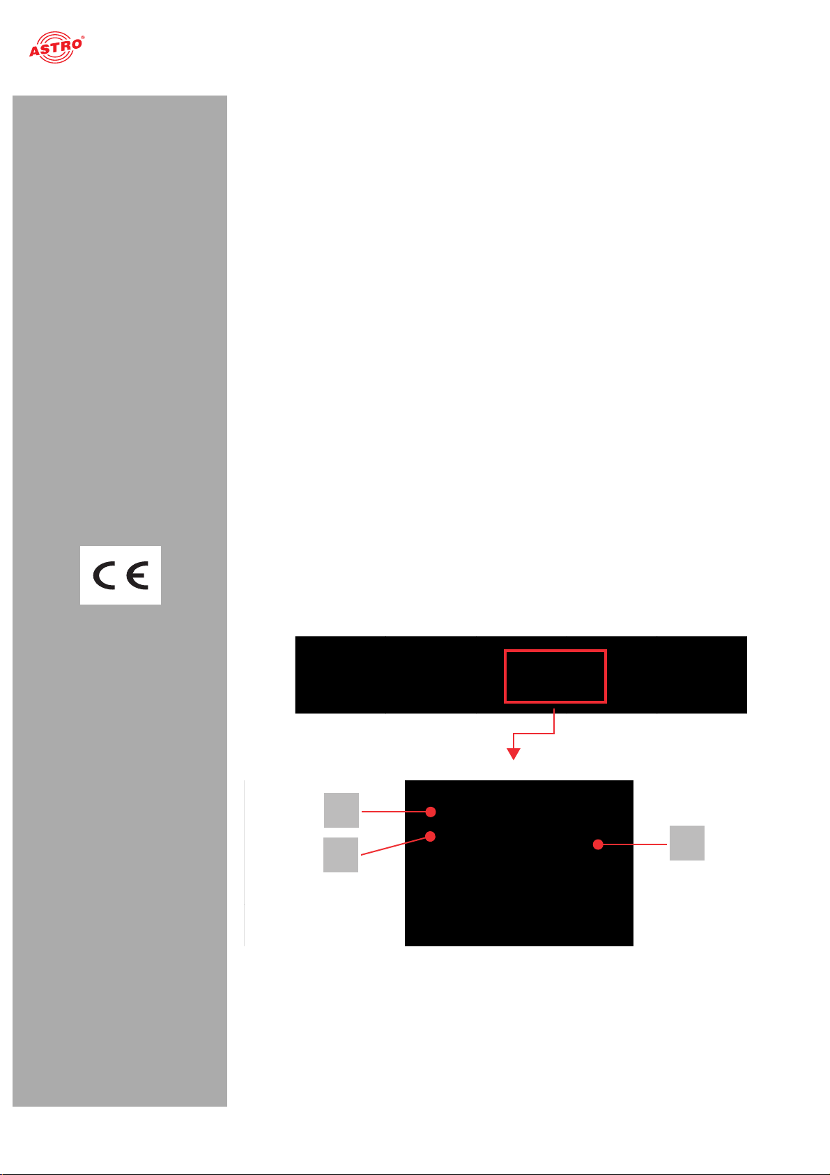
Figure 1, top:
U 158, installed in the U 100 base unit
(fitted with three plug-in modules)
Figure 1, middle:
U 158, front panel
[1] Display for management IP addresses,
data IP addresses, status messages, etc.
[2] Status display
[3] Control and data knob, menu switch
Device description
The delivery is comprised of the following parts:
U 158 Edge QAM module and backplane Operating manual
The U 158 plug-in module and the U 100 base unit feature a CE marking. This confirms that the products conform to the relevant EC directives and adhere to the requirements specified therein.
2
3
1
Figure 1: U 158
Operating manual U 158 - Version 10-2018Apage 4
Page 5

Device description
HINWEIS: Turning the data knob [3] (fig. 2, above) allows you to navigate through the indi-
vidual menu items in the U 158 display. Press the data knob to activate the display.
The ASTRO logo will be the first display to appear following activation.
Turning the data knob clockwise allows to you access the individual displays:
Log messages: The last messages entered in the log book are displayed.
Interface settings: IP addresses of the network interface.
Software versions: The version of the plug-in module software currently installed is displayed.
Alarm table: The current error messages are displayed.
RF output: The programs currently selected are displayed.
The different text colours refer to:
Red: Error (the corresponding display in the web interface log book is: “error”) Yellow: Warning (the corresponding display in the web interface log book is: “warning”)
Operating manual U 158 - Version 10-2018A
Purple: Critical error (the corresponding display in the web interface log book is: “critical / alert /
emergency”)
Light blue: Info (the corresponding display in the web interface log book is: “info”) Light green: Notice (the corresponding display in the web interface log book is: “notice”)
page 5
Page 6

Important safety information
Important safety information
To avoid any potential risks to the greatest extent possible, you must adhere to the following safety information:
ACHTUNG: Failure to observe this safety information may result in personal injury due
to electrical and thermal dangers!
Proper use
Only use the device at the approved operating sites and in the ambient conditions allowed (as
described in the following), and only for the purpose described in the section “Proper use”.
Before starting operation of the device
HINWEIS: Read this operating manual attentively! It contains important information
about installation, ambient conditions and maintenance of the device. Keep this operating
manual for future use and for handover in the event of a change of owner or operator. A PDF
version of this manual is available to download on the ASTRO website (there may be a more
recent version).
Check the packaging and the device for transport damage immediately. Do not start operation of
a device that has been damaged.
Transporting the device by the power cable may damage the mains cable or the strain relief, and
is therefore not permitted.
Installation and operation
The device may only be installed and operated by qualified persons (in accordance with EN
60065) or by persons who have been instructed by qualified persons. Maintenance work may only
be carried out by qualified service personnel.
The module can only be installed in U 100-230 and U 100-48 base units. The safety information
in the operating manuals of the base units must be obeyed in addition to the safety information
described in this manual.
The installation site must be planned in a way that prevents children from playing with the device
and its connections.
In order to prevent inadmissible operating statuses from occurring, only the components
described in this manual, or components approved by the manufacturer for the base unit, may be
used.
The ambient temperatures specified in the technical data must be complied with, even when
climatic conditions change (e.g. due to sunlight). If the device overheats, the insulation used to
isolate the mains voltage may be damaged.
The device and its cable may only be operated away from radiant heat and other sources of heat. To avoid trapped heat, ensure there is good ventilation on all sides (minimum interval of 20 cm to
other objects). Installing the device in a niche or covering the ventilation openings is not permitted.
The device does not feature protection against water and may therefore only be operated and
connected in dry rooms. It must not be exposed to splash water or drip water, condensation or
similar effects of water, as this may impair the isolation from the mains voltage.
Do not install the unit in locations with excessive dust formation, as this may impair the isolation
from the mains voltage.
Electromagnetic compatibility (EMC)
In order to avoid malfunctions from occurring when operating radio and telecommunications equipment, as well as other operating units or broadcasting services, the following points must be observed:
Before installation, the device must be checked for mechanical damage. Damaged or bent covers
or housings may not be used.
During operation, the device must always be covered by the components provided for this
purpose. Operation with an opened cover is not permitted.
The braided line or the contact springs may not be damaged or removed.
Operating manual U 158 - Version 10-2018Apage 6
Page 7

Warranty conditions
Maintenance
The operating display only shows whether the DC current, which supplies the device components,
has been disconnected. However, operating displays (on the power supply unit or the device) that
are not lit up in no way indicate that the device is completely disconnected from the mains. There
may still be voltages in the device that are dangerous to touch. You may therefore not open the
device.
Read carefully: EN 60728-11 – Part 1, Safety requirements / No service tasks during electrical
storms!
Repair
Repairs may only be performed by the manufacturer. Improperly performed repairs may result in
considerable dangers for the user.
If malfunctions occur, the device must be disconnected from the mains and authorised experts
must be consulted. The device may need to be sent to the manufacturer.
General information
Store or use the device in a safe location, well out of reach of small children. It may contain small
parts that can be swallowed or inhaled. Dispose of any small parts that are not needed.
Plastic bags may have been used for packaging the device. Keep these plastic bags away from
babies and children in order to avoid any danger of suffocation. Plastic bags are not toys.
Do not store the device near chemicals or in places in which a leakage of chemicals may occur.
Organic solvents or fluids in particular may cause the housing and/or cables to melt or disintegrate,
presenting a danger of fire or electric shock. They may also cause device malfunctions.
Warranty conditions
The general terms and conditions of ASTRO Strobel GmbH apply. You will find these in the current catalogue or on the Internet under “www.astro-kom.de”.
Disposal
All our packaging materials (cardboard boxes, insert sheets, plastic films and bags) are fully recyclable.
After use, this device must be disposed of as electronic waste in an orderly manner according to the
current disposal regulations of your district / country / state.
ASTRO Strobel is a member of the Elektro system solution for the disposal of packaging materials. Our contract number is 80395.
Performance description
The U 158 is a plug-in module, which is only intended for use in the base units
U 100-230 and U 100-48. It can receive up to 8 MPEG data streams and channels encapsulated in
accordance with Internet Protocol (IP). These are converted in up to 2 x 4 QAM adjacent channels and
are output using the two HF outputs in the U 158.
To use the devices properly, read the following safety and operating instructions attentively.
The U 158 plug-in module features the following performance characteristics:
Conversion of up to 8 IP gigabit Ethernet multicast groups QAM channels are output in 2 x 4 adjacent channels Outstanding output parameters provided by Direct Digital Technology
Operating manual U 158 - Version 10-2018A
page 7
Page 8
Connecting and installing the module
Connecting and installing the module
HINWEIS: The instructions for the base unit U 100 include a description of how to prepare
the base unit for installation.
Observe that you need to insert an SD memory card into the module prior to installation in the
base unit (see figure at left).
Coding and installing the backplane
A backplane is included with every U 1xx signal converter. This is used to establish a mechanical
connection between the signal converter and the base unit. Both the mains HF connections and the
network connections are connected to this
backplane. There is usually a temperature-controlled fan for cooling the signal converter on the
backplane. This can be replaced while the device is operating.
To ensure the position of the backplane, and therefore the position of the respective signal converter
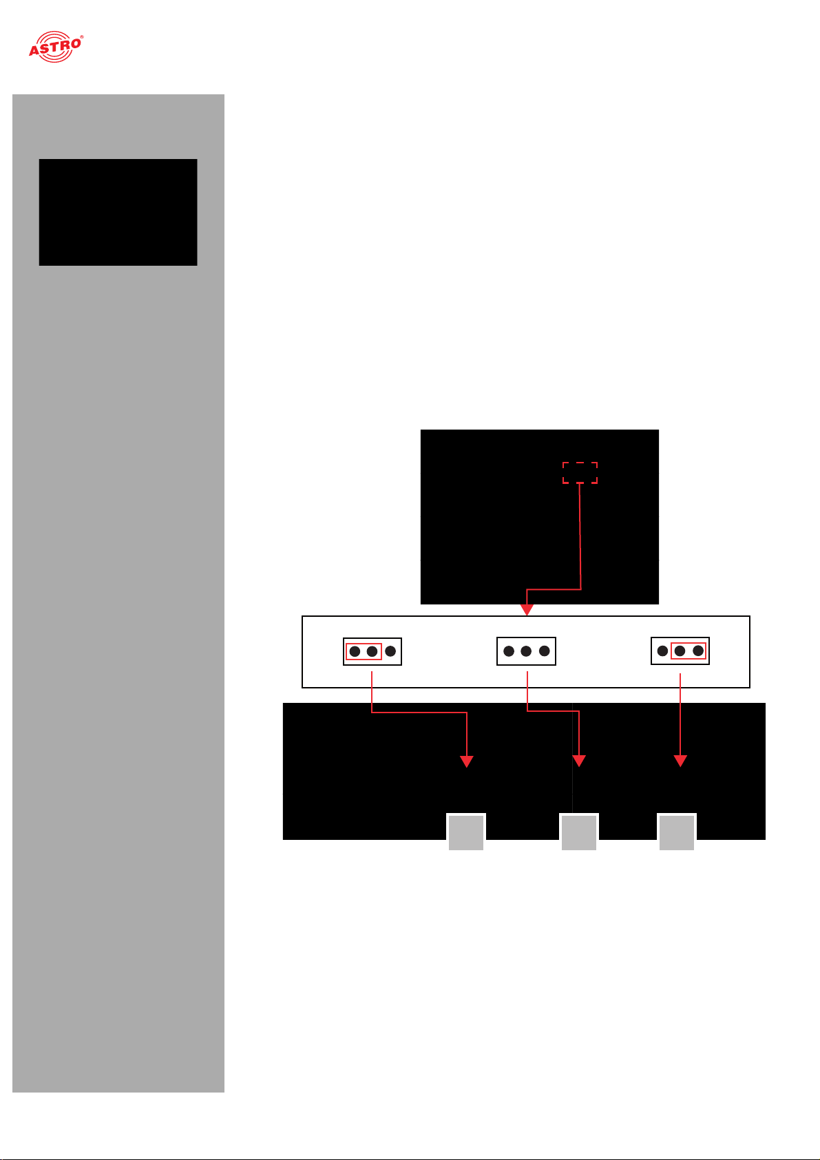
in the U 100 base unit, is correct, you must plug a corresponding jumper into the circuit board on the
backplane. Proceed as described in the following.
[1] Left slot [2] Middle slot [3] Right slot
1 2
Figure 2: Coding the backplane by plugging in the jumper
3
Operating manual U 158 - Version 10-2018Apage 8
Page 9
Connecting and installing the module
To prepare the backplane for installation, proceed as follows:
Plug the jumper into the installation position provided in accordance with figure 2
(page 7).
HINWEIS: A jumper which has not been correctly plugged into the corresponding installa-
tion position will result in incorrect LED displays on the front of the U 100 base unit (see section
“Device description”). Furthermore, the correct position cannot be displayed on the web
browser user interface.
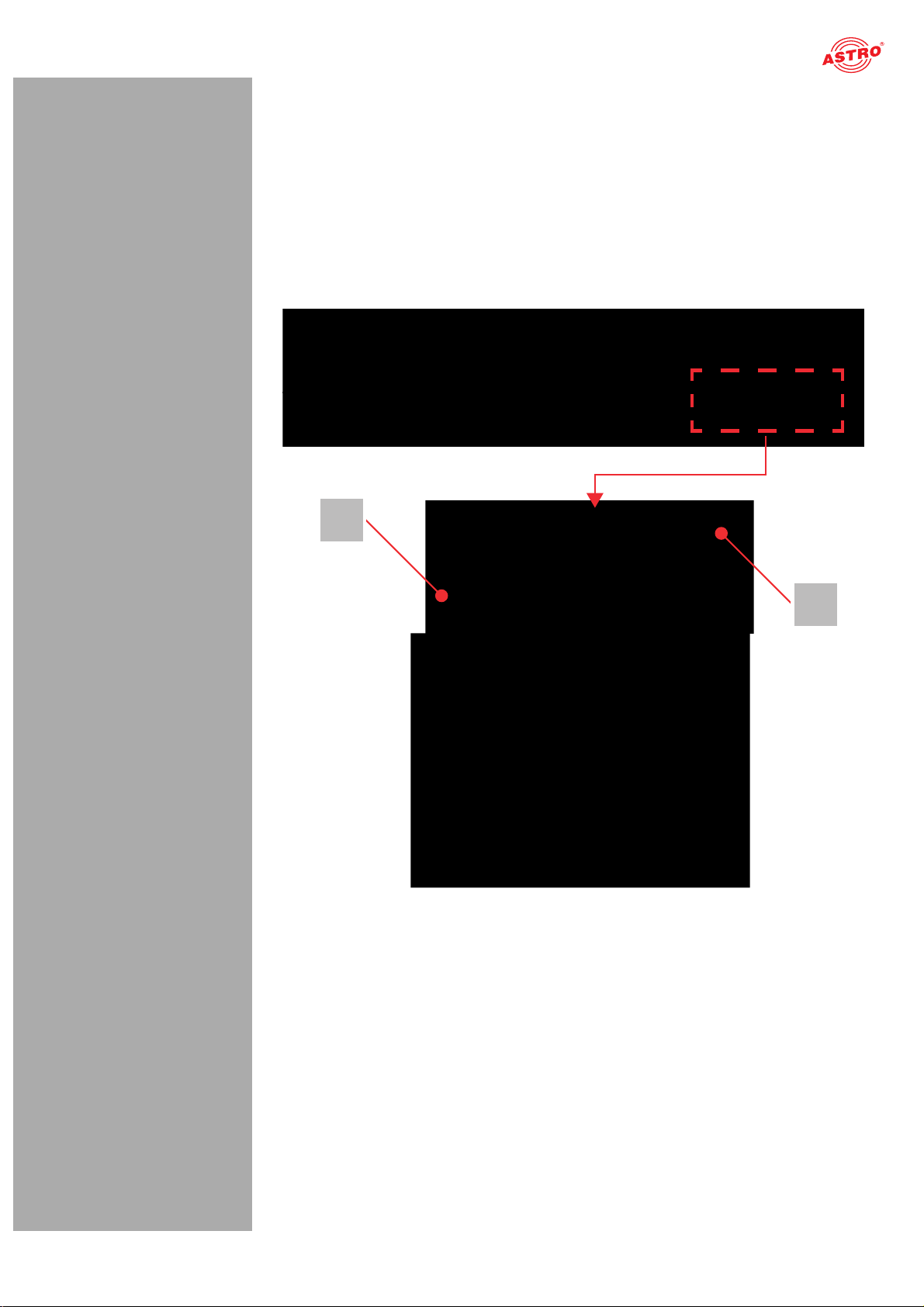
You can now install the backplane in the base unit. To do so, proceed as follows:
[1, 2] Phillips-head screws [3] Cable for signal supply [4] Cable for power supply
1
2
Figure 3: Installing the backplane in the base unit
Operating manual U 158 - Version 10-2018A
page 9
Page 10

Connecting and installing the module
AUFGABE
1. When the U 100 base unit is in its delivery state, the three installation slots for the backplanes are
covered by dummy plates (see figure 3, above). Start by removing the Phillips-head screws [1] and
[2] from the dummy plate at the required installation position (left, middle or right) and remove the
dummy plate.
2. You can now see the two connection cables for the selected slot (power supply and signal cable). Connect the cables to the backplane as shown in figure 3 (above).
3. Now carefully insert the backplane into the slot of the U 100. Make sure the cables are not jammed. You can push the backplane into the housing by applying light pressure.
ERGEBNIS:
The backplane is now connected and installed. Once installed, it should correspond to the figure at the
left.
Operating manual U 158 - Version 10-2018Apage 10
Page 11

Quick start - starting operation of the U 158
Quick start - starting operation of the U 158
Connecting the U 158 to a PC or laptop
To be able to configure the U 158, you now need to connect the network sockets (Management A or Management B) on the backplane of the device (see figure at left) to your PC or laptop using a network cable.
Once you have connected the base unit to the power supply, the U 158 will switch on automatically.
Once it has booted (approx. 90 seconds), the ASTRO logo initially appears in the display.
Turn the knob to the right of the display clockwise until the menu item “Interface settings” is displayed.
The two management IP addresses (Management A and Management B) for the device now appear in
the upper lines.
Make a note of the address of the management connection which you are using for your PC or laptop
to ensure you can enter this in the address line of your web browser later on.
HINWEIS: Please note that your PC or laptop must be in the same sub-network as the
U 158! The sub-network mask of the U 158 is set to 255.255.255.0 upon delivery. The PC or
laptop which is connected must therefore be assigned an IP address 192.168.1.x.
You can now start the configuration using the web browser user interface.
General information on the structure of the web browser interface
The configuration interface is divided into the following sub-areas:
1
2
Figure 4: Structure of the web browser interface
3
Operating manual U 158 - Version 10-2018A
page 11
Page 12

Quick start - starting operation of the U 158
Status line (header) [1]: displays general information on the module.
SW: Software status
FW: Current version of the software installed
HW: Hardware version
Up: Runtime since the system was booted
Time: Date and time
Name, location, contact: corresponds to the settings which were made in the “User settings”
configuration area
Navigation menu [2]: displays the individual configuration areas which can be selected by
clicking the mouse. A detailed description of these areas can be found on the following pages of
this chapter.
Content area [3]: The respective configuration form – depending on the menu item selected – is
displayed here.
HINWEIS: The browser display is not updated automatically. Use the corresponding button
in the menu of your browser to update the display.
Logging in
To log in, enter the IP address of the U 158, which appears in the device display, into the address line
of the browser. The menu page “Status” will then appear. Select the item “Log in” from the navigation
menu at the left. The input mask for the log in should then appear (see figure 6, below). In delivery state,
you must use the following log-in data:
User name: “user” or “admin” (input without inverted commas)
Password: astro
Figure 5: Log in
After logging in, the start page of the U 158 with all relevant system information will appear. The navigation menu and the log-in status display will appear at the left.
Only one user can be logged into the user interface of the U 158 at a time. The current user is displayed in the column at the left, below the menu.
The device status is indicated by a green or red circle. If a green circle is displayed, the device is operational. If the circle is red, then a fault has occurred.
A list of current errors is available under the menu item “Active alarms”.
HINWEIS: For reasons of security, you should change the access data valid upon delivery
(user name and password) to prevent unauthorised access!
The procedure is described in the section “Changing user data”.
Operating manual U 158 - Version 10-2018Apage 12
Page 13
Quick start - starting operation of the U 158
Changing the IP address
HINWEIS: If you wish to change the IP address, then the settings on the PC must be changed
accordingly. IP addresses can only be changed by the administrator!
Start by changing the IP addresses for the management and the data port. To do so, click on the item “Main” in the menu at the left. You will now see the following table in the content area:
Figure 6: Changing the IP address
You can enter the IP addresses for management ports A and B as well as for data ports A and B in the “Address” line. Make sure that you activate the ports being used by activating the corresponding radio button in the line “Active”.
To save your changes, click on the “Submit” button below the last table.
More information on configuring the IP address can be found in the section “Configuring IP interfaces,
IP management and base unit”.
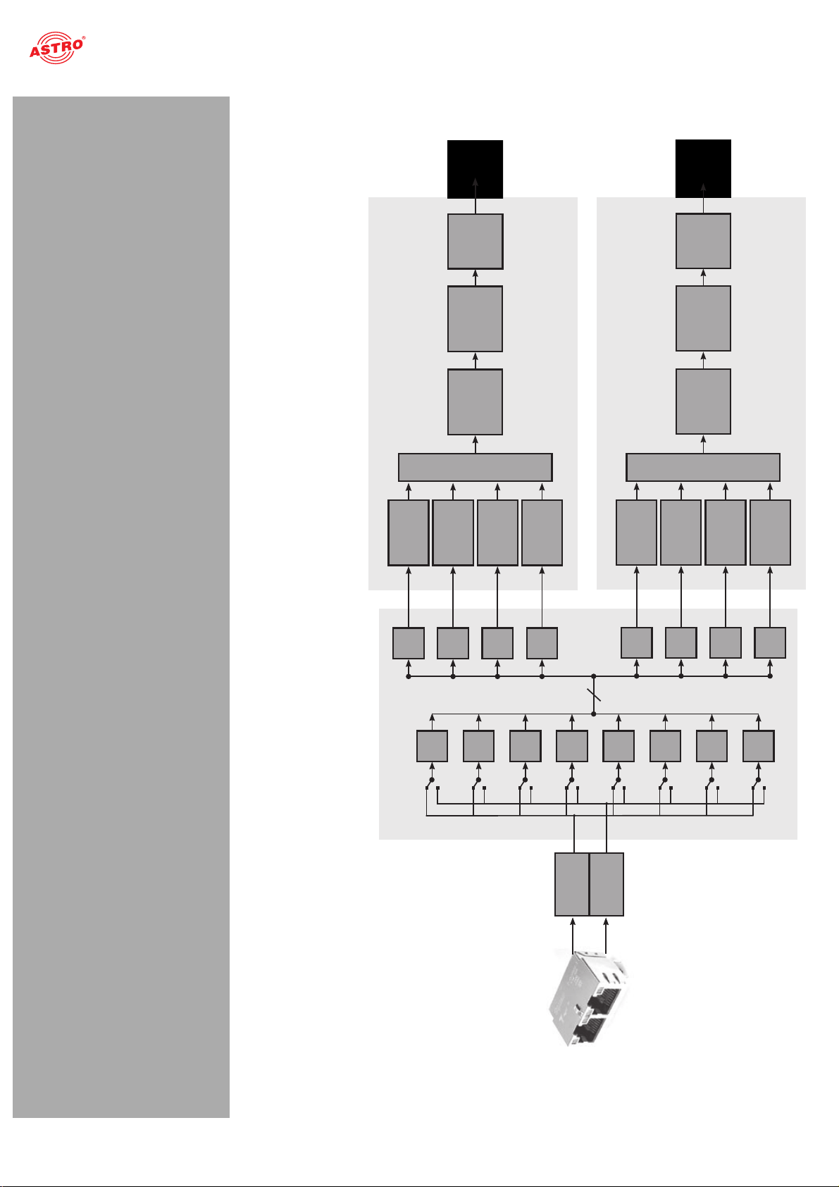
The signal flow in the U 158
The overview on page 10 shows the possible signal paths for the U 158. The specific signal flow can be divided into the following sub-areas:
The IP receivers (1 to 8) receive a signal via data port A or B (each can be switched). There are two QAM modulators, each of which features a transport stream selector for selecting
a transport stream for each QAM channel.
The level of the output signals from the two QAM modulators (each with 4 QAM channels) are each
adapted, filtered and amplified, and are conveyed to an HF output on the backplane.
Operating manual U 158 - Version 10-2018A
page 13
Page 14
Quick start - starting operation of the U 158
Data A
Ethernet
Data B
8
U158
IP
RX1
IP
RX2
IP
RX3
IP
RX4
IP RX
IP
RX5
IP
RX6
IP
RX7
IP
RX8
+
TS
Sel1
TS
Sel2
TS
Sel3
TS
Sel4
RF1
RF
Amplifier
RF
Attenuator
Band /
Channel
Filter
Modulator1
Modulator2
Modulator3
Modulator4
+
TS
Sel5
TS
Sel6
TS
Sel7
TS
Sel8
RF2
RF
Amplifier
RF
Attenuator
Band /
Channel
Filter
Modulator1
Modulator2
Modulator3
Modulator4
Figure 7: The signal flow in the U 158
Operating manual U 158 - Version 10-2018Apage 14
Page 15
Quick start - starting operation of the U 158
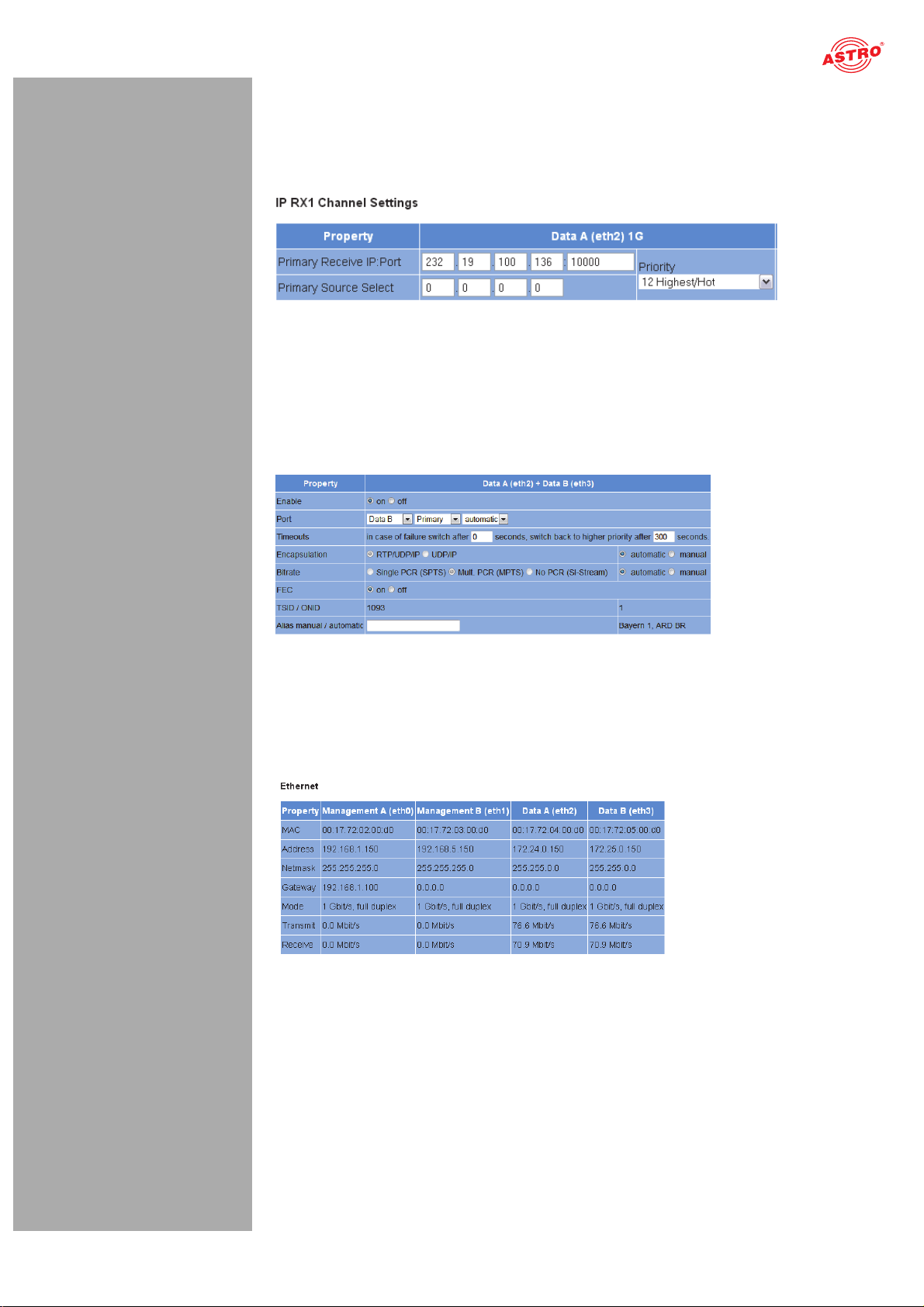
Configuring the IP receiver
Now start configuring a signal path in the U 158. Start by clicking on the item “IP RX 1” in the web browser interface menu. You will now see the following table:
Figure 8: Setting the source for the data stream
Enter the IP address and port for the data source in the first line. Optionally, you can also enter a
source select address in the second line.
Further information about configuring the receiver can be found in the section “Configuring IP inputs”.
There is another table below the “IP RX 1 Channel Settings” table. Activate the radio button “on” to
enable the receiver.
Figure 9: Activating the connection to the data port
Checking the data reception rate
Now click on the menu item “Status” in the menu at the left. You will now see the following overview:
Figure 10: Displaying reception statistics
A data reception rate > 0 at data ports A or B should now appear in the line “Receive” in the “Ethernet” table.
Operating manual U 158 - Version 10-2018A
page 15
Page 16
Quick start - starting operation of the U 158
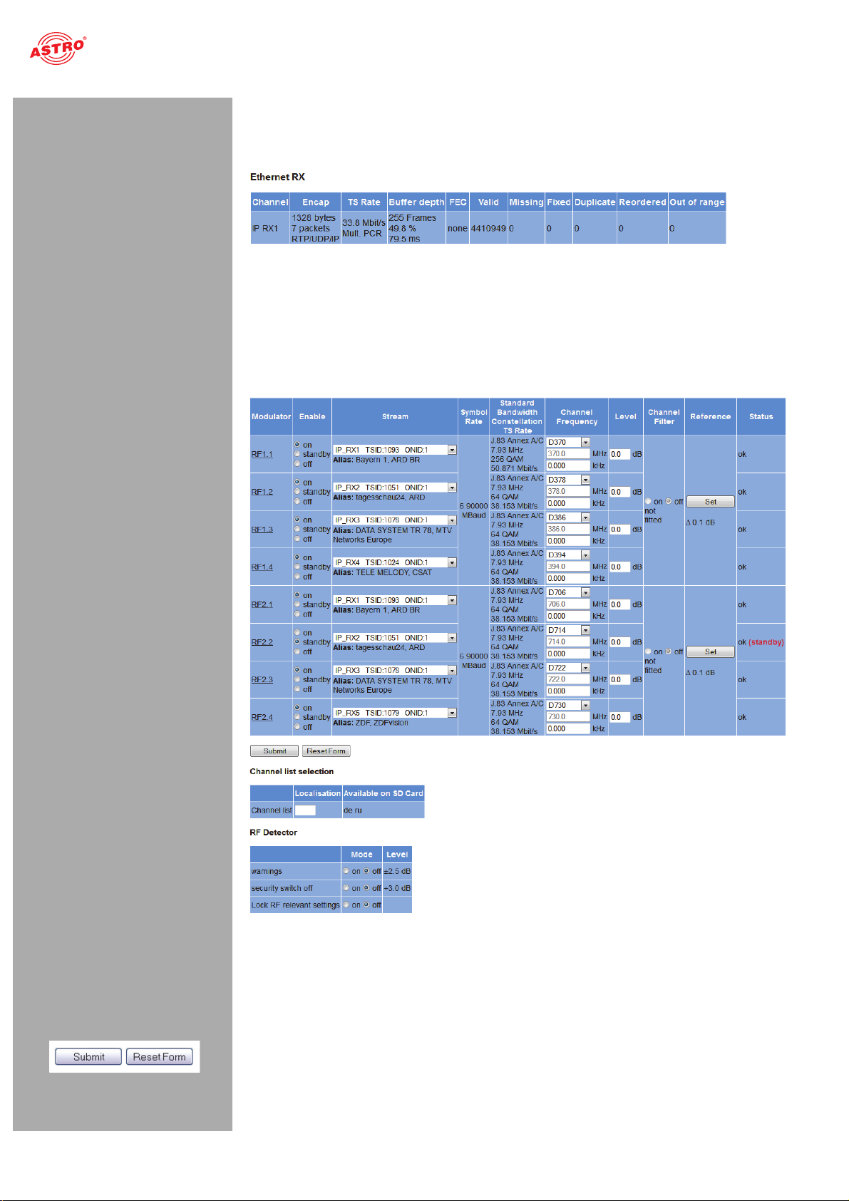
Now click on the menu item “Statistics” in the menu at the left. Details about the transport stream received are provided in the “Ethernet RX” table. A TS rate of > 0 should be displayed. If this is not the
case, check the receiver settings.
Figure 11: IP receiver statistics
Configuring HF output channels
To complete the process, you should configure and activate the HF output channels. To do so, click on the menu item “RF” in the web browser interface menu. You will now see the following table:
Figure 12: Configuring HF output channels
For an example of this, select one of the modulators by clicking on the “On” radio button in the “Enable” column.
Select the incoming data stream for conversion from the drop-down menu. The drop-down menu
shows all data available streams with reception using the eight IP receiv ers. Enter the preferred values
for the frequency and the level in the corresponding input field in the “Channel Frequency” and “Level”
columns respectively.
To save your changes, click on the “Submit” button below the table.
More information on setting the HF modulators can be found in the section “RF menu”.
Operating manual U 158 - Version 10-2018Apage 16
Page 17
“Status” menu
“Status” menu
To have the current settings for the U 158 displayed, click on the Status item in the menu at the left. You can now see the overview shown in figure 13:
Figure 13: Status display
The following tables are displayed:
Operating manual U 158 - Version 10-2018A
page 17
Page 18
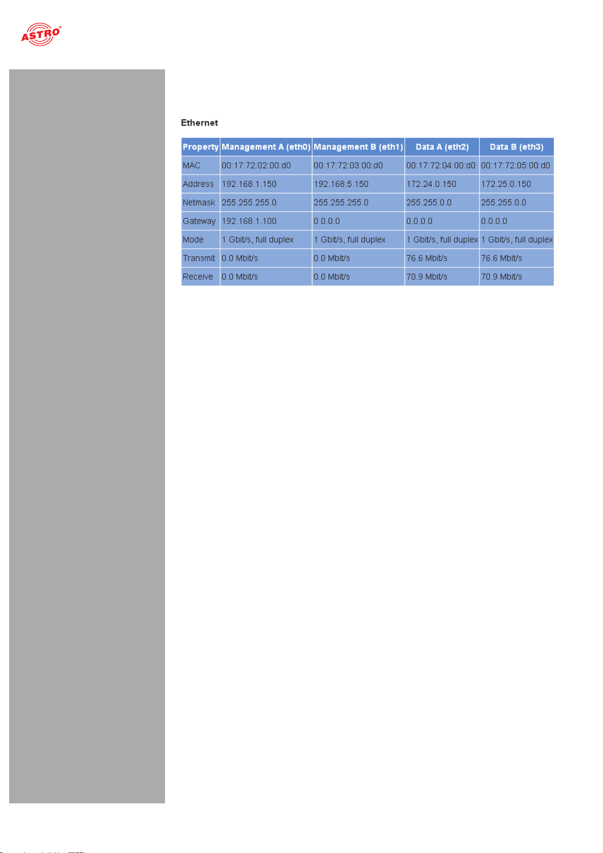
Ethernet status:
Configuration data and status of the Ethernet port
Figure 14: Status display - Ethernet
“Status” menu
The values for the following parameters are displayed and configured here respectively in accordance
with the four connections on the backplane of the U 158 (Data A, Data B, Management A and Management B, see section “Device description”).
MAC: MAC address (display value)
Address: IP address (configurable)
Netmask: Net mask (configurable)
Gateway: Gateway IP address (configurable)
Mode: Ethernet mode (display value)
Transmit: Data transmission rate (display value)
Receive: Data reception rate (display value)
Operating manual U 158 - Version 10-2018Apage 18
Page 19

“Status” menu
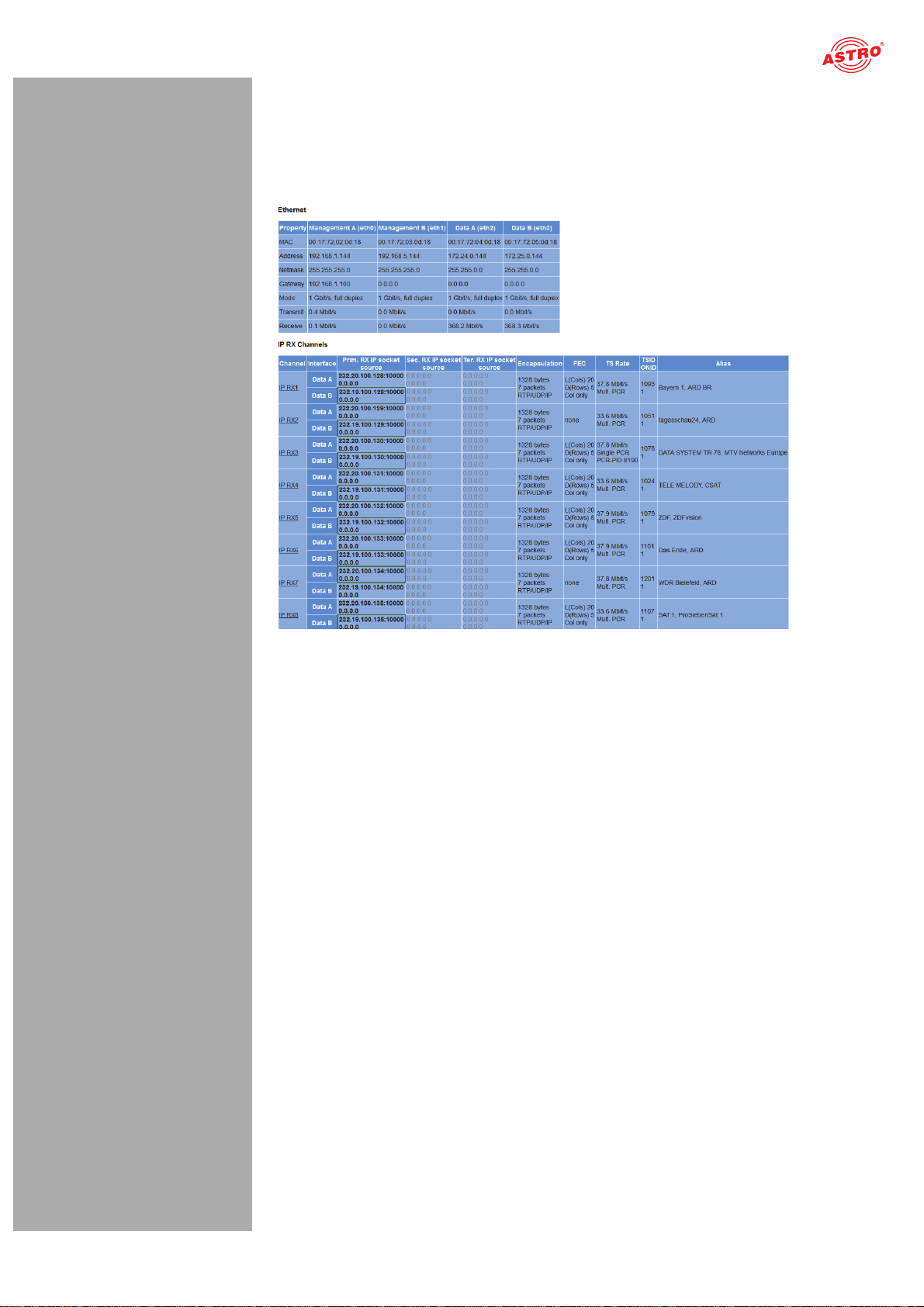
Status display of the IP receiver:
Figure 15: Status display - IP RX channels
The different text formats refer to:
Green: active Grey: inactive (“off”) Black (bold): priority “hot”, no errors Red (bold): priority “hot”, errors Black (standard): priority “cold”, no errors Red (standard): priority “cold”, errors
The values set for the following parameters are displayed in the table “IP RX channels” for the 8 IP receivers – for outputs Data A and B respectively:
Prim. RX IP socket source: Primary source
Sec. RX IP socket source: Secondary source
Ter. RX IP socket source: Tertiary source
Encapsulation: Data encapsulation
FEC: Forward error correction
TS Rate: Data rate
TSID ONID: Transport stream ID / original network ID
Alias: Alias name
Operating manual U 158 - Version 10-2018A
For details on the parameters: see the section “IP RX menu”
page 19
Page 20

Status display of the QAM output programs:
“Status” menu
Figure 16: Status display - RF channels
The values set for the following parameters are displayed in the table “RF channels” for the 2 x 4 QAM output channels:
Modulator: Output program
Stream: Transport stream received
Symbol Rate: Symbol rate for the QAM modulators 1 and 2
Standard Bandwidth Constellation TS Rate: Modulation standard, required channel
bandwidth, BAM constellation, output bit rate
Standard Bandwidth Constellation TS Rate: Modulationsstandard, benötigte Kanal-
bandbreite, BAM Konstellation, Ausgangsbitrate
QAM Buffer: Maximum and mean value in % and stuffing in Mbit/s
Channel Frequency/Level: selected frequency/slected level
Reference: Deviation from the calibrated value
Status: Status of each channel (OK or OFF)
Details on the parameters can be found in the section “Menu RF”.
Operating manual U 158 - Version 10-2018Apage 20
Page 21

“Status” menu
Status messages on temperature, internal voltages and the power module:
Figure 17: Status display - Miscellaneous
The following, general parameters are displayed in the “Miscellaneous” table:
Temperature 1 (center): Temperature displayed in °C for the mainboard
Temperature 2 (front): Temperature displayed in °C for the mainboard
Temperature 3 (rear): Temperature displayed in °C for the mainboard
Temperature 4 (PA): Temperature displayed in °C for the HF output stage
Supply 1.2 V: 1.2 V supply voltage
Supply 1.5 V: 1.5 V supply voltage
Supply 1.8 V: 1.8 V supply voltage
Supply 2.5 V: 2.5 V supply voltage
Supply 3.3 V: 3.3 V supply voltage
Supply 5.5 V: 5.5 V supply voltage
Supply 9 V: 9 V supply voltage
Fan: Fan rotation speed
Power Module: Functional status (OK or error message)
Operating manual U 158 - Version 10-2018A
page 21
Page 22

Memory status:
Figure 18: Status display - System resources
“Status” menu
Information on the internal resources of the operating system can be viewed in the “System resources” table. No settings can be made here.
File resources:
Number of left files FOPEN_MAX Number of left files NFILE Number of free descriptors NFD
CPU load, averaged over XXs:
CPU load 0.1 s CPU load 1 s CPU load 10 s
Operating manual U 158 - Version 10-2018Apage 22
Page 23

“Main” menu
“Main” menu
This section explains how to make general settings for the interfaces and the management of the U 158, as well as for the U 100 base unit. Click on the item “Main” in the menu at the left.
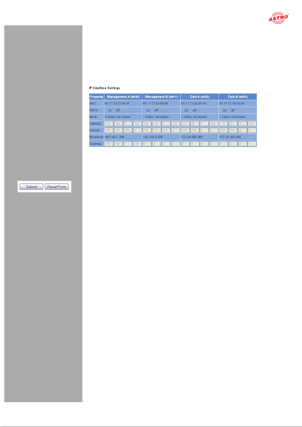
Setting IP interfaces (administrator only)
You can configure IP interfaces and activate or deactivate them using the table shown above (“IP interface settings”). The connection type is automatically identified and displayed by the U 158 (in this case:
1 GBit/s, full duplex).
Figure 19: Configuring IP interfaces
The following parameters are displayed, and can be configured:
MAC: MAC address of the respective interface
Active: Activate the radio button “on” to activate the interface. Activate the radio button “off” to
deactivate the interface.
Mode: Connection type (identified automatically)
Address: IP address
Subnet: Netmask
Broadcast: Broadcast address
Gateway: Gateway IP (if required)
HINWEIS: When programming the IP addresses, make sure the addresses have not already
been allocated within your network. Address conflicts result in network malfunctions. (Please
set unused parameters to 0.0.0.0.)
To save your changes, click on the “Submit” button below the last table.
Configuring management settings
You can configure the following management settings in the second table (“IP management settings”):
Operating manual U 158 - Version 10-2018A
Figure 20: Configuring management settings
page 23
Page 24

“Main” menu
DNS: Enter a DNS server, if required, in the input fields.
SNTP server: You can enter one or two time servers here (SNTP protocol).
Time Source: Select the preferred time reference from the drop-down menu. The following
options are available for selection: “SNTP server” and “IP RX 1 - 16”.
To save your changes, click on the “Submit” button below the last table.
Configuring the base unit
You can enter settings for the U 100 base unit in the third table (“U 100 Rack settings”).
Figure 21: Configuring the U 100 base unit
The following parameters are displayed, and can be configured:
Base Address: Enter an address for the base unit being used here. If the
U 158 is managed using the U 100-C controller and several U 100 base units are being used, then
each base unit must be allocated an address of its own.
This setting only has to be entered for one module per base unit.
Slot Address: In accordance with the coding of the backplane of the U 158 performed previ-
ously (see section “Installing and connecting”), the address corresponding to the slot in the base
unit is displayed here.
Power Modules: Select the number of power modules used from the drop-down menu
(“0” for 48 V operation, “1” or “2” for 230 V power modules).
To save your changes, click on the “Submit” button below the last table.
Saving and loading configurations / default and reboot
Figure 22: Saving and loading configurations
Changes to the configuration of the U 158 are written to the device by clicking the “Submit” button, and
are activated immediately. If you wish to save the current status to a separate memory, click on the
“Save 2nd” button (below the tables). This current status is then saved to the SD card in the U 158.
(Please note that prior to installing the module, an SD memory card must be plugged
in; see figure at left.)
Operating manual U 158 - Version 10-2018Apage 24
Page 25

“Main” menu
Click on the “Default” button if you wish to restore the default settings.
You can retrieve this status again by clicking on the “Load 2nd” button. How to save the configuration
onto the local computer or FTP server is explained in the section “Software update and configuration
files”.
Clicking the “Force Save” button saves the configuration with immediate effect. The configuration will otherwise only be saved after 10 seconds if no further change is made; and after 30 seconds at the latest.
ACHTUNG: If you click the “Default” button, all settings except for the user and network
settings for the data and management ports are reset to the delivery state.
Click on the “Reboot” button to restart the unit with the last settings saved.
Operating manual U 158 - Version 10-2018A
page 25
Page 26

“Test generator” menu
“Test generator” menu
The U 158 features an integrated test generator for a functional test when an input signal is not yet available. Null packets are generated with a preset packet ID. The maximum data rate that can be set totals 67 MBit/s.
Figure 23: Test generator
The following settings are displayed, and can be configured:
Data rate: Enter the preferred data rate in MBit/s in the input field.
Packet ID: Enter the packet ID here.
Packet length: Packet length is displayed.
To save your changes, click on the “Submit” button below the table.
Operating manual U 158 - Version 10-2018Apage 26
Page 27

“IP Channel” menu
“IP Channel” menu
To have the input masks for configuring the input and output channels displayed, click on the item “IP Channels” in the menu at the left.
You can check the settings for the input channels in the table at the bottom, “IP RX channel settings”.
Figure 24: IP RX channel settings table
You can activate or deactivate the respective IP inputs here by clicking on the corresponding radio button. The following parameters are displayed for ports A and B respectively for the four IP input channels:
Prim. RX IP socket source Sec. RX IP socket source Ter. RX IP socket source Encapsulation TSID / ONID Alias
HINWEIS: These parameters are explained in more detail in the section “IP RX menu”.
If you change the activation or deactivation status of inputs or outputs in one of the two tables, then click
on the “Submit” button below the last table to save your changes. Click on “Reset form” to restore the
original settings.
Operating manual U 158 - Version 10-2018A
page 27
Page 28

“IP RX” menu
“IP RX” menu
To configure the 8 IP inputs, start by clicking on the item “IP RX 1”, “IP RX2”, “IP RX3”, “IP RX4”, “IP
RX5”, “IP RX6”, “IP RX7” or “IP RX8” in the menu at the left. The following table will then appear in the
content area at the top:
Figure 25: Table 1 “IP RX1 channel settings”
“Receive IP” and “Port” (see lines 1, 3 and 5 in the table) form a socket on which the incoming data
stream is received. This also allows the Receive IP address to be a multicast address or a unicast address of its own.
The IGMP protocol is used to request an IP multicast. If version 3 of this protocol is used, then you can
select a specific source using the Source Select IP address (see lines 2, 4 and 6 in the table). If this
function is to remain unused, please enter four zeroes in the input field. (This is, for example, the case
when IGMP version 2 or IGMP version 3 from any source is being used as the protocol).
You can make a priority setting for the primary, secondary and tertiary IP address / port respectively
using a drop-down menu. There are 13 options (from “off” to “highest/hot”) available for selection.
The priorities are divided into three groups:
Hot standby (higher priorities) Levels 7 - 12: data streams are requested permanently Cold standby (medium priorities): Levels 1 - 6 “Off”
As a rule – providing there are no network provider problems – the data stream with the highest priority
is received and used for processing. In the event of a fault – failure of the incoming signal – a
switch-over is made to the data stream with the next-highest priority.
If a priority level from the “Hot standby” group is allocated to a data stream, then this will continue to be
requested even during network provider problems. As soon as the problem has been rectified, it switches back to this data stream.
Operating manual U 158 - Version 10-2018Apage 28
Page 29

“IP RX” menu
Another table is shown in the following in which settings valid for Data Port A and B can be entered.
Figure 26: Table 2 “IP RX1 channel settings”
Enable: Activate or deactivate the IP input by clicking on the corresponding radio button.
Port: Configure the reception source for the IP channel here.
Select either Data A or Data B as the port from the first drop-down menu.
Select either the “Primary”, “Secondary” or “Tertiary” option from the second drop-down menu.
Select the “static” option from the third drop-down menu if you do not wish to use an automatic
replacement circuit for the data streams. Select the “automatic” option when the replacement
circuit should be used as described above.
Timeouts: Enter a time frame, in seconds, in the first input field after which a switch-over to the
data stream with the next-lowest priority should occur in the event of a fault.
Enter a time frame, in seconds, in the second input field after which it should switch back to the
data stream with the higher priority after the problem has been rectified. (This is only the case
when a priority level from the “Hot standby” group was allocated to the data stream - see explanation above).
Error condition: If the data rate should be the only factor considered in the event of a fault,
activate the radio button “data rate only”. Otherwise, select the radio button “data rate, continuity
count, service”.
Encapsulation: When the radio button “RTP / UDP / IP” has been activated, the corresponding
RTP / UDP / IP data streams are received. If you activate the radio button “on” in the line “FEC”,
then the additional receive IP ports +2 and +4 will be received (example: apart from 10000, also
10002 and 10004). This also includes additional redundancy information for fault correction.
When the radio button “UDP / IP” has been activated, either UDP / IP data streams or RTP / UDP
/ IP data streams without an evaluation from RTP are received.
Select either “automatic” or “manual” for the data encapsulation by clicking the corresponding
radio button.
Bitrate: Select either “automatic” or “manual” by clicking the corresponding radio button. If
“manual” is selected and the radio button “Single PCR” has been selected at the same time, then
the receive data stream is regulated using a single PCR. This is not suitable for transport streams
with several PCRs.
If you activate the radio button “Multi PCR”, then the data rate is used for regulation. This is not
possible for data streams with a variable bit rate.
When the “SI Stream” button has been activated, the U 158 expects “Service Information
Stream”-only reception, without PCR, on this receiver and adapts the minimum bit rate.
FEC: Activate or deactivate FEC by clicking the radio button “on” or “off”. (See “Encapsulation”
above.)
TSID / ONID: The respective value is displayed but cannot be changed.
Operating manual U 158 - Version 10-2018A
Alias manual / automatic: You can enter an alias name for the data stream in the input
field at the left. The automatically generated alias name is displayed at the bottom right. This is the
name of the first transmitter in the data stream. This is used if no name is entered manually.
Click on the “Submit” button below the last table to save the changes.
Click on “Reset form” to restore the original settings.
page 29
Page 30

“RF” menu
“RF” menu
To configure the QAM outputs, start by clicking on the “RF” item in the menu at the left. The following table will then appear in the content area at the top, in which the most important settings for all output channels can be entered.
Figure 27: Table 2 “RF channels”
Enable: To activate or deactivate an output channel, click the corresponding radio button. If you
select the “Standby” option, the decoder will run, but the corresponding output will be switched off.
This may be practical when, for example, the module is being used as a replacement module in a
redundant circuit.
Stream: Select the incoming data stream for conversion from the drop-down menu. The
drop-down menu shows all available data streams received using the eight IP receivers. The last
item in the drop-down menu is the ASTRO test generator, which generates a digital radio program
with a 1 kHz tone in the output channel which has been set.
Symbol Rate: This displays the symbol rate currently configured for the output channel.
Standard Bandwidth Constellation TS Rate: The QAM standard, the bandwidth of the
output channel, the modulation type and the output data rate are displayed here.
Operating manual U 158 - Version 10-2018Apage 30
Page 31

“RF” menu
Channel Frequency: Select an item from the drop-down menu for the channel. Once a value
has been selected from the list, the input field for the output frequency remains inactive, and the
corresponding channel centre frequency is displayed. If you select the “manual” option, you can
enter the channel centre frequency manually.
There may be a 32 MHz interval between the start frequency of the RF X.1 and the end frequency
of the RF X.2 within a channel pair (RF 1.1 / 1.2 / 1.3 / 1.4 or RF 2.1 / 2.2 / 2.3 / 2.4); e.g. RF 1.1
= S06 and RF 1.2 = S 09 when there is a channel width of 8 MHz. If the interval set is too large,
then an error message will appear. The output channel affected will then be set to “Standby” and
must be reactivated when a new, and correct, configuration is set. If no adjacent channel assignment has been configured, then a channel filter cannot be used for the respective pair of channels.
Level: The level of the output signal is equalised here. You can set the relative level in incre-
ments of 0.1 dB by entering the corresponding value in the input field. The range which can be set
depends on the type of modulation set (QAM 64 to +10 dB, QAM 256 to +4 dB). If you set a value
which is excessively high, an error message appears. Once this message has been acknowledged, the maximum value is entered.
If you change the type of QAM modulation of a pair of output channels, the level will be
adjusted automatically.
Channel Filter: If you wish to activate a channel filter, select an item from the “min.” or “max.”
drop-down menus and activate the radio button “on”.
Note that the channel filter for the corresponding output channel must be connected (see figure at
left).
In order to be able to activate the channel filter, the limits configured in the “Channel Filter” column
must exhibit the same values as the output channels entered under “Channel Frequency”. Filter
limits which deviate from the output channel can, of course, also be used, however in this case,
this filter will not be able to be activated.
Reference: Click on the “Set” button to select the value entered within the modulation parame-
ters as the reference. A 2.5 dB deviation from the output signal will result in a warning message
being issued.
Click on the “Submit” button below the last table to save the changes.
Click on “Reset form” to restore the original settings.
The table “Channel List Selection” is found below the table “RF Channels”.
Figure 28: “Channel list selection” table
The language version of the channel list can be selected in the input field “Localisation”. “us” (USA), “de” (German), “fr” (French), “ru” (Russian) and “be” (Belgium) are available.
If stored on the SD memory card, you can use the country code (e.g. “ru”) to activate a different channel list.
Operating manual U 158 - Version 10-2018A
page 31
Page 32

“RF” menu
The table “RF Detector” can be found further down.
Figure 29: “RF Detector” table
The U 158 features a level detector in the output. This level detector consistently measures the output
level. When you click the “Set” button in the “Reference” column in the table “RF Channels” (further up),
then the value entered in the modulation parameters is saved as a reference. The deviation from this
value is measured on an ongoing basis.
The consequences of any deviations which may occur can be configured in the table “RF Detector”.
You can, for example, activate or deactivate the warning message for the level deviation by clicking on
the corresponding radio button. When the warning message is activated and the level deviation totals
+/- 2.5%, then the warning message is recorded in the log file and, depending on the configuration of
the SNMP properties, a trap occurs. Furthermore, you can activate or deactivate a security switch-off
in the event of a deviation of +/- 3%.
Activating or deactivating the “Lock RF relevant settings” option remains possible. If the option has
been activated, only the service for conversion can be changed in the table “RF Channels”. All other
settings in this table are locked. All configuration options relating to the HF output channel in the modulator settings (menus RF 1.1 to RF 2.4) are also locked.
Click on the “Submit” button below the last table to save the changes.
Click on “Reset form” to restore the original settings.
Operating manual U 158 - Version 10-2018Apage 32
Page 33

“RF 1.X” and “RF 2.X” menu
“RF 1.X” and “RF 2.X” menu
To enter detailed settings for the individual output channels, start by clicking on the item “RF 1” or “RF
2” in the main menu at the left, and then clicking on one of the submenu items “RF 1.1 to RF 1.2” or “RF
2.1 to RF 2.2”. The “Input Selection” table now appears in the upper part of the content area:
Figure 30: “Input selection” table
You can select the program to be converted to QAM here. This program can be converted from any of the 8 IP receivers.
Click on the “Submit” button below the last table to save the changes.
Click on “Reset form” to restore the original settings.
Another table follows in which you can complete all the settings relating to the QAM output signal.
Figure 31: “Modulation” table
The following settings can be entered individually.
Standard: The U 158 is able to generate QAM channels in accordance with the DVB-C standard
Annex A/C or in accordance with ITU-T J.83 Annex B. Depending on the standard selected, the
selection options in the “Defaults” line, in which the modulation type and the channel bandwidth
are selected, will change.
When you...
Defaults: The modulation type and the channel bandwidth are set here by selecting them from
the drop-down menu. Activate the checkbox “Apply changes to all RF X.X channels” if the selection made should be applied to all output channels of the U 158.
Operating manual U 158 - Version 10-2018A
page 33
Page 34

“RF 1.X” and “RF 2.X” menu
Parameter: When you have selected the option “Manual” from the drop-down menu in the
“Defaults” line, you can select the modulation type and the spectrum inversion from a drop-down
menu manually, allowing it to be set manually. The settings selected here apply to both channels
of the respective pair of output channels.
If the option “ITU-T J.83 Annex B” has been selected in the “Standard” line, then a selection can
also be made for “Interleaving Mode”. Interleaving mode determines the degree of reference data
interleaving during transmission via the QAM channel. The first number determines the number
of paths used for transmission, while the second number specifies the basic delay within a path.
The interleaver makes a higher level of transmission reliability possible on a transmission channel
affected by burst errors.
When you have selected the option “Manual” from the drop-down menu in the “Defaults” line, then
you also have the option of configuring the stuffing unit. When you select the option “TS-Packet
Stuffing”, then zero packets are generated with a useful content comprised of zeroes. If, in
contrast, you select the option “PRBS-Packet Stuffing”, then the useful content of the zero packets
generated is comprised of a random sequence.
Spectrum: When you have selected the option “Manual” from the drop-down menu in the
“Defaults” line, then you can enter the symbol rate in the corresponding input field manually and
select a value for the roll-off factor from the drop-down menu.
Click on the “Submit” button below the last table to save the changes.
Click on “Reset form” to restore the original settings.
If you click on the “Refresh” button, all information in the table is updated.
Another table follows in which you can edit the transport stream.
Figure 32: “Transport stream processing” table
The following settings can be entered individually.
SID/PID-Filter: You can activate or deactivate the transport stream filter here by clicking on
the corresponding radio button. The option of configuring drop filters or pass filters is also
provided. Click on the corresponding radio button here. The drop filter removes the selected IDs
from the transport stream, while the pass filter transmits the selected IDs only and discards all
others.
If you select a service filter using an SID filter, all subordinate PIDs which belong to the service
are also removed from the transport stream, or are transmitted. When a PID filter is used, only the
PID selected is removed or transmitted respectively. The respective PIDs selected are displayed
in the SID or PID list once selected. The PIDs for filtering can be activated by clicking the Add
button. Clicking the “Remove” button deletes entries with a marked checkbox again.
PID Remapping: The U 158 provides a PID remapping function, which means that PIDs active
on the input side can be renamed, and be added to the output data stream with a new PID. To set
this type of filter, select a PID from the drop-down menu and then enter the new PID in the input
field “Output-PID” and confirm it by clicking the “Add” button. Renamed PIDs appear in the
“Remapping List”. If you wish to remove a remap filter again, then mark the checkbox for the entry
in the remapping list, and then click the “Remove” button.
Click on the “Submit” button below the last table to save the changes.
Click on “Reset form” to restore the original settings.
If you click on the “Refresh” button, all information in the table is updated.
Operating manual U 158 - Version 10-2018Apage 34
Page 35

“TS processing” menu
“TS processing” menu
To enter settings for TS processing, start by clicking on the item “TS Processing” in the main menu at the left. The following tables now appear in the upper part of the content area:
Figure 33: Settings for transport stream processing
You can make settings for the PAT processing, NIT processing and the NIT upload here.
You can activate and deactivate PAT processing for the individual output channels in the “PAT Processing” table by clicking the corresponding checkbox (see below).
If a service filter has been applied, then the PAT is adapted accordingly.
Figure 34: “PAT processing” table
Click on the “Submit” button below the table to save the changes.
Click on “Reset form” to restore the original settings.
Operating manual U 158 - Version 10-2018A
page 35
Page 36

“TS processing” menu
You can complete the settings for the NIT processing in the table which follows.
Figure 35: “NIT Processing” table
In the „Mode“ drop down list you can choose from the following options (depending on the chosen mode there are different options available):
OFF: No NIT will be generated.
Static NIT: If you choose this mode a static NIT will be generated. In line „Use different NIT
on RF2“ you can generate a second NIT for the second output by activating the radio button „Yes“.
When the radio button „enabled“ is activated in line „Update Service List Descriptors of NIT file“,
the static NIT-file will be updated dynamically with information, that describes the services of each
transport stream. Therefore it is reasonable to link the modules in this part of the net via the file
„Modules.xml“. This enables writing of the service list descriptors of all transport streams.
Whn the radio button 2enabled“ is activated in line „NIT Verification“, an external NIT is used. In
this case the module can adjust the actual configuration to the configuration specified in the NIT
and alarm in case of any deviation. You can find these information in the „NIT“ menu.
In line „NIT Insertion Interval“ you can type in the output rate of the NIT in milliseconds. 8000 ms
for example means that every 8 seconds a complete NIT is generated.
Dynamic NIT: If you choose this mode a dynamic NIT will be generated.
Every NIT has a version number. In line „Set Version of NIT“ you can define a specific value for
this number. That value will then be incremented with every change of the NIT. This is useful for
synchronisation of different facilities. In case of redundancy switching from one facility to the other
would not change the NIT.
In line „NIT Insertion Interval“ you can type in the output rate of the NIT in milliseconds. 8000 ms
for example means that every 8 seconds a complete NIT is generated.
Remap NIT from PID: If a NIT should be existant in the data stream under a PID other than
0x0010, it can be used via remap filter in the output data stream. To do so you must choose the
desired input channel from the drop down list in line „Source NIT“ and type in the input PID for the
output channel into the input field.
When the radio button „enabled“ is activated in line „NIT Verification“, an external NIT will be used.
In tis case the module can adjust the actual configuration to the configuration specified in the NIT
and alarm in case of any deviation. You can find these information in the „NIT“ menu.
In line „NIT Insertion Interval“ you can type in the output rate of the NIT in milliseconds. 8000 ms
for example means that every 8 seconds a complete NIT is generated.
Remap PID from PID Slave: This mode can not be selected and is displayed only for infor-
mation purposes on the modules. It belongs to the mode „Remap NIT from PID“. A module that is
operated in this mode acts as a master if other modules are synchronised via the „Modules.xml“
file. In this operating mode the master stes every module into the „Remap NIT from PID Slave“
mode. It transmits a NIT, tt can be found on the chosen IP-RX channel and the chosen PID.
When the radio button „enabled“ is activated in line „NIT Verification“, an external NIT will be used.
In tis case the module can adjust the actual configuration to the configuration specified in the NIT
and alarm in case of any deviation. You can find these information in the „NIT“ menu.
In line „NIT Insertion Interval“ you can type in the output rate of the NIT in milliseconds. 8000 ms
for example means that every 8 seconds a complete NIT is generated.
Click on the “Submit” button below the table to save the changes.
Click on “Reset form” to restore the original settings.
Operating manual U 158 - Version 10-2018Apage 36
Page 37

“TS processing” menu
The “Connected Modules” table follows. This allows you to select whether the configuration of the
U 100-C Management Controller should be used for generating a dynamic NIT.
Click on the corresponding radio button to do so. This will update the file “nit.xml”, with the “Generate
from local NIT; use NIT 1” mode having to be set on all RF ports.
Figure 36: “Connected modules” table
Click on the “Submit” button below the table to save the changes.
Click on “Reset form” to restore the original settings.
Operating manual U 158 - Version 10-2018A
page 37
Page 38

“NIT” menu
“NIT” menu
If you wish to create a static NIT, start by clicking on the one of the corresponding menu items, “NIT 1” or “NIT 2” in the main menu at the left. The following table now appears in the upper part of the content area:
Figure 38: “Change network information” table
You can enter the network ID and the network name in the respective input fields here.
Click on the “Submit” button below the last table to save the changes.
Click on “Reset form” to restore the original settings.
If you click on the “Refresh” button, all information in the table is updated.
The table “Add External Transport Streams” follows. You can add an external transport stream here.
Figure 39: “Change network information” table
The following parameters can be configured individually:
TS-ID: Enter the transport stream in the input field.
ON-ID: Enter the ON ID in the input field.
Channel Frequency: Select the preferred output frequency from the drop-down menu. If you
select the “manual” option, you can enter the frequency in MHz in the input field manually.
Constellation: Select the preferred modulation type from the drop-down menu.
Symbol Rate: Enter the symbol rate in MS/s in the input field.
Once you have configured all the parameters, click on the Add button to add the transport stream.
Operating manual U 158 - Version 10-2018Apage 38
Page 39

“NIT” menu
Another table follows in which the NIT is listed with all entries.
Figure 40: “NIT” table
Sort the entries by clicking on the corresponding arrow button in the “Sort” column. To delete an entry, activate the respective checkbox in the “Remove” column.
Click on the “Submit” button below the last table to save the changes.
Click on “Reset form” to restore the original settings.
If you click on the “Refresh” button, all information in the table is updated.
Operating manual U 158 - Version 10-2018A
page 39
Page 40

“LCN” menu
“LCN” menu
If you wish to create an LCN table, start by clicking on the menu item “LCN” in the main menu at the left. The following table now appears in the upper part of the content area:
Figure 41: “Service selection for creation of LCN table” table
You can enter an LCN in the left column and select the preferred service from the drop-down menu in
the right column respectively.
Click on the “Add selected services to LCN table” button to add your selection to the LCN table.
Keep in mind that the entries added will only be saved after you have clicked the “Submit” button below
the table which follows, the “LCN Table”.
The “LCN Table” table follows. A list of all the services currently selected appears here. To delete an entry from the list, activate the checkbox for the respective service in the “Remove” column.
Figure 42: “LCN table” table
You can select the type of description for the table (“NorDig (V1)” or “IEC 62216”) to the right of the
LCN table. The descriptor corresponding to this standard is then generated in the NIT.
Activate the radio button which corresponds to your selection.
Click on the “Submit” button below the last table to save the changes.
Click on “Reset form” to restore the original settings.
If you click on the “Refresh” button, all information in the table is updated.
A selection of print views for the LCN table, the TV program overview and the radio program overview follows further down. Click on the respective button to have the print view displayed.
Operating manual U 158 - Version 10-2018Apage 40
Page 41

“SSL Settings” menu
“SSL Settings” menu
HINWEIS: A licence is required to use the SSL functions.
To enter SSL settings, click on the item “SSL Settings” in the main menu at the left.
There is a checkbox in the upper table “SSL Settings” which displays the rerouting of HTTP requests to the secured version HTTPS. After input of the licence, the checkbox is activated.
Figure 43: “SSL Settings” table
In the following table, “Generate a CSR for this device”, individual items of information about the device can be entered (“Certificate Signing Request”: address, organisation, etc.).
Figure 44: “Generate a CSR for this device” table
By clicking the “Download CSR” button, you can create a “Certificate Signing Request” with which your
CA can issue a certificate for the device. The input field “Private key use” shows you whether the device's own key, or the key which was entered and saved, is being used.
There is a third table, “Key and certificate settings”, below this.
Figure 45: “Key and certificate settings” table
“
Operating manual U 158 - Version 10-2018A
page 41
Page 42

“SSL Settings” menu
yes
yes
yes
User has deposited
certicate?
User key exists and ts
to certicate?
Use user key and
certicate
Use user certicate and
generated key
Use generated
crticate and key
Does user certicate
t to generated key?
no
no
no
This table allows you to:
Upload a device key (click on the “Search” button and select the preferred file; then click on the
“Upload key” button)
Delete an existing device key (click the “Clear key” button) Upload a device certificate (click on the “Search” button and select the preferred file; then click on
the “Upload certificate” button)
Delete an existing device certificate (click the “Clear certificate” button) Regenerate a device key and device certificate (click the “Regenerate” button)
If you change the activation or deactivation status of inputs or outputs in one of the two tables, then
click on the “Submit” button below the last table to save your changes. Click on “Reset form” to restore
the original settings.
The device administers two keys/pairs of certificates: “generated” and “user”. The following figure shows which certificate and which key are used.
Figure 46: Using the certificates/keys
Operating manual U 158 - Version 10-2018Apage 42
Page 43

“User Settings” menu
“User Settings” menu
Click on the menu item “User Administration” in the main menu at the left to have the corresponding input mask displayed. The input mask shown in figure 38 now appears.
Figure 47: User administration
You can create up to four users for the user interface of the U 118. The following three users have been created as the default setting:
user admin controller
The password for all three users is “astro”.
To change the access data for a user account, or to create a new one, enter the preferred user name
in the input field User name. Then enter the preferred password in the input field New Passw ord, and
confirm it by typing it in the input field Retype New password again.
HINWEIS: A password must contain at least 5 characters. If the checkbox „Enforce
password policy“ is activated, a password must contain at least 8 characters and special types
of characters.
To delete a user account, activate the corresponding checkbox Delete for the respective account in the right column of the table.
The following settings can also be entered:
Timeout: You can enter a time for the automatic logout, in minutes, in this input field. If no more
inputs are made in the user interface, then automatic logout will occur once the time entered here
has elapsed.
The time remaining until automatic logout is displayed under the main menu, in the left column of
the user interface.
Name, Location, Contact: You can save a name for the system, the location and the contact
data for a person in these input fields. They are displayed in the status line.
Enforced Password Policy: Activate the checkbox when a password should have a
minimum of 8 characters, and include at least one lower-case letter, one upper-case letter, one
number and one special character.
Operating manual U 158 - Version 10-2018A
Disallow anonymous access: Activate the checkbox when access to the content area
(tables) should only be possible after logging in.
WICHTIG: All changes will only become effective after you have clicked on the “Submit”
button below the input mask. Click on the “Reset Form” button to delete the input values again.
page 43
Page 44

“User Settings” menu
Another table follows in which you can enter information for a RADIUS server. A licence is also required for the RADIUS server function.
Figure 48: RADIUS administration
The following individual items of information can be entered:
RADIUS Server Address RADIUS Server Port RADIUS Shared Secret RADIUS Server Retries RADIUS Server Timeout
HINWEIS: Users that are configurated on the device will be deactivated when a RADIUS
server is configurated!
The RADIUS server must be configurated. Users with service type „Administrative“ are administrators of the device.
When the checkbox „Enable Radius Login“ is clicked, the RADIUS function is activated, if the
RADIUS Server is accessible. If this is not the case,, the RADIUS function remains inactive and
the following message appears: „RADIUS logins have not been enabled because the connection
check failed“.
You can create a white list for all incoming IP data in a further table. In this case, only IP data will be processed which come from a source entered in the white list.
Figure 49: White list administration
The following parameters can be specified for four IP sources respectively:
IP address Netmask
Operating manual U 158 - Version 10-2018Apage 44
Page 45

“TS Analyzer” menu
“TS Analyzer” menu
The U 118 can be equipped with a Transport Stream Analyzer by purchasing a licence. This Analyzer
displays the structure of the MPEG2 TS, from the tables to the individual PID and its service. Click on
the “TS Analyzer” submenu to access the selection of the transport stream for analysis. The following
input mask now appears:
Figure 50: Transport stream analyzer
To analyse a transport stream, click on the corresponding radio button in the “Analyze” line and then
click on the “Submit” button. If you wish to reset your inputs, click on the “Reset” button.
HINWEIS: The two buttons “Submit” and “Reset” are only visible when this module has
been licensed. If this is not the case, the link “No licence” will appear instead. Click on this, or
the item “Licence” in the menu at the left to access the “Licensing” input mask (more detailed
explanation of this is found in the section “Licensing”).
Operating manual U 158 - Version 10-2018A
page 45
Page 46

“Licensing” menu
“Licensing” menu
A number of functions of the U 118 (e.g. the TS Analyzer) can only be used after being enabled by
means of a licence key.
The licence key with the respective function can be purchased from ASTRO. You will receive a licence
key with which you can activate the functions using the web browser interface.
The format of the licence key is a text document (e.g. Lic001772000222.txt).
To activate the functions, start by clicking on the “Licensing” item in the menu at the left. The following
input mask now appears:
Figure 51: Enabling licences using the licence key
Now enter the licence key sent to you in the input field. The key or keys can be entered in the input
mask using “Copy & Paste”. Then click on the “Submit” button to transmit the text to the device. If the
licence is valid, this is confirmed with the message “License is valid”. An error message is displayed for
an invalid licence.
To order additional licences, the MAC address of the device must be specified.
You will find the MAC address on the web browser interface in the “Licensing” submenu (HWID). After
the MAC address has been submitted, the licence keys are generated by ASTRO are sent by e-mail
or on a CD.
Operating manual U 158 - Version 10-2018Apage 46
Page 47

“Update/config.” menu
“Update/config.” menu
The menu item “Update/config.” allows you to update the firmware version of your device and upload and download a variety of configuration data.
Firmware update from a local memory location
You will require an update archive for updating the device firmware. This can be downloaded from the
ASTRO firmware server (address: “http://astro-firmware.de/Headend-Firmware/u1xx”). The file name
of the archive required ends in “.up”. The name is comprised of the type designation of the device (U
118) and a four-digit version number.
Once the update archive has been downloaded, start by selecting the item “Update/Config.” in the
menu of the user interface. The “Software update” table then appears in the content area at the top.
Figure 52: Firmware update
Now click on the “Search” button and select the path to the memory location of the update archive
downloaded beforehand.
Then click on the “Update and Reboot” button to start the update process. Please wait for the process
to be completed, and for the device to reboot.
Available Update Archives
The table tabelle „Available Update Archives“ shows an overview update-archives already stored in the module (up to ten). Users can have access to older software versions (Installation or deleting).
Bild 53: Firmware Update
Uploading and downloading configuration files
Operating manual U 158 - Version 10-2018A
Figure 54: Loading/saving configuration files
Configuration files can be uploaded and downloaded. To upload files, use the “Search” button to select the preferred file. Then click on the “Upload” button to start the uploading process.
The following files are available for download:
System settings (XML format)
Simply click on the corresponding file link to download the file.
page 47
Page 48

Downloading configuration/status files
Figure 55: Loading status files
The following files are available for download:
Module info (XML format)
IP configuration (XML format)
System status (XML format)
System measurements (XML format)
“Update/config.” menu
Simply click on the corresponding file link to download the file.
Loading/saving firmware and configurations using (T)FTP
You can update firmware using a (T)FTP server using the table “Firmware update and configuration via server” and load or save configuration files.
Figure 56: Loading/saving firmware updates and configurations using (T)FTP
To carry out the preferred action, start by selecting an action from the drop-down menu in the “Mode”
line. The action can only be carried out when the server path specified does actually exist. Furthermore,
any firewalls that have been installed must be configured in a way that allows (T)FTP communication.
Operating manual U 158 - Version 10-2018Apage 48
Page 49

“Update/config.” menu
The following individual actions are available for selection:
“Load config from server” action: A configuration stored on the (T)FTP server is transmitted to
the U 118 and can be activated immediately. The IP settings for the data and management interfaces on the device are not changed. The file “settings.xml” are written onto the U 118.
“Save config to server” action: The current configuration of the U 118 is written to the (T)FTP
server. The configuration includes the following files:
- “ip.xml” (IP settings for the data and management interfaces)
- “settings.xml” (all other settings, e.g. IP receiver and modulator settings)
- “user.xml” (user data)
“Update firmware from server” action: If you select this action, you must specify the preferred
software version under Version (a 4 character maximum applies). One the update is successful,
the message “Firmware update OK. Please reboot to use the new firmware version” appears.
“Load firmware from server” action: If you select this action, you must specify the preferred soft-
ware version under Version (a 4 character maximum applies). The software selected is written
to the SD memory card, but will not be unpacked.
“Unpack *.up archive” action: If you select this action, the update archive is unpacked and saved
to the SD memory card (specify the version number).
“Update firmware from SD card” action: If you select this action, the update archive is unpacked,
saved to an SD memory card and programmed into the module (enter the version number).
“Overwrite backup firmware” action: The device software is saved in two partitions. The software
saved in the first partition is used for operating the module, while the second partition is used to
keep a backup copy ready for the event that the update process fails. As long as both partitions
are different, the information “Backup differs” will be displayed in the menu “Active Alarm Table”.
The current software is copied to the backup partition when this action is carried out.
Once you have selected an action, you can add any information still missing from the remaining lines of the table:
(T)FTP Server address: Address of the server
Protocol: Activate the radio button “FTP” if you wish to use the more comprehensive FTP
protocol. Activate the radio button “TFTP” if you wish to use the more basic TFTP protocol.
FTP User name: This depends on the settings for the FTP server used (for astro-firmware.de
e.g. “anonymous”).
FTP Password: This depends on the settings for the FTP server used (for astro-firmware.de e.g.
“astro”).
Path: Path to the location where data are saved, or from where the data can be loaded. The path
must be specified in relation to the root directory of the FTP server, and must always begin with a
“/” and end with a “/” as well (enter without quotation marks).
Version: Enter the version number of the software which you wish to download or save here.
HINWEIS: If the update is carried out using the TFTP protocol, then filling in the input
fields “FTP User name” and “FTP Password” is not necessary.
Operating manual U 158 - Version 10-2018A
page 49
Page 50

“System Log” menu
“System Log” menu
To have the system log displayed, click on “System log” in the menu at the left. The following overview will now appear:
Figure 57: System log
You can check or configure the following parameters individually:
System log settings
Figure 58: Filter settings for the system log display
You can activate or deactivate filters for displaying the log entries here. To have messages from the corresponding category displayed, activate the checkbox allocated to the category.
HINWEIS: You can connect to higher-level management systems using the “Syslog” and
“SNMP” parameters.
Operating manual U 158 - Version 10-2018Apage 50
Page 51

“System Log” menu
Management Information Base (MIB)
The NSMP MIBs available are stored on the device and can be downloaded by using the download link below the table “System Log Settings”.
System log
Figure 59: Logfiles
Click on the “Refresh” button to update the system log display. The entries in the system log are sorted
chronologically according to the time at which the event occurred.
If you do not wish for the existing entries to be displayed after a refresh, activate the checkbox “Checkbox to clear log on refresh”. Once the checkbox has been activated, after a refresh, the process of deleting the old log entries is listed as the first entry (specified the user account and the current time upon
deletion).
You can also download the following logfiles:
System log (CSV format)
Debug log (CSV format)
Downloading log files
Figure 60: Downloading log files
A maximum of 2,500 lines is displayed in the “Log files” table. The complete log file can be downloaded from the “Download Log Files” table by clicking on the file name XX.csv.
Operating manual U 158 - Version 10-2018A
page 51
Page 52

“Alarm severities” menu
“Alarm severities” menu
You can change the alarm settings for diverse parameters or deactivate the alarm display for a parameter, when preferred. To do so, click on the item “Alarm Severities ” in the menu at the lef t. A set of tables
for different parameter groups then appears:
Figure 61: Alarm Severities
The preset options for the alarm messages are identified by a green frame. Retaining these settings is recommended.
Operating manual U 158 - Version 10-2018Apage 52
Page 53

“Active alarms” menu
“Active alarms” menu
To have the “Active Alarm” table displayed, click on the corresponding item in the menu at the left. The following table now appears:
Figure 62: Active alarm table
The table provides information about error messages currently active. The “Message” column shows the error message in plain text.
HINWEIS: You can also access the “Active Alarm Table” by clicking the red point in the
status line in the upper section of the user interface.
Operating manual U 158 - Version 10-2018A
page 53
Page 54

“Statistics” menu
“Statistics” menu
To have data transmission statistics for the U 118 displayed, click on the “Statistics” item in the menu
at the left. All statistics relevant to the operation of the device and which can be used for analysis are
displayed here. The following individual tables are displayed:
Ethernet bandwidth
Figure 63: Ethernet bandwidth
The transmission rates for sending (transmit) and reception (receive) are specified for the respective interfaces Management A, Management B, Data A and Data B.
Ethernet frames
Figure 64: Ethernet frames
The following parameters are displayed for the interfaces Data A and Data B, in this order:
The number of IP frames transmitted to the processor is specified in the first three lines of the
table.
Number of defective frames. Number of frames which could not be allocated. Number of frames which could not be allocated due to exceeding the total buffer depth. The number of frames transmitted per transport stream in total or per second is displayed in lines
7 to 10 for each IP transmitter.
The number of frames forwarded to the IP receiver (primary, secondary and tertiary respectively)
are displayed in the last line.
Operating manual U 158 - Version 10-2018Apage 54
Page 55

“Statistics” menu
Ethernet RX
Figure 65: Ethernet RX
The following parameters are displayed for the individual IP receivers:
Encap: The number of bytes in the IP payload for each frame is specified in the upper line; below
this, the number of TS packets per frame is displayed. The lower line specifies whether the transmission occurs by UDP / IP or TRP / UDP / IP. The transmission protocol is selected under the
menu item “IP RX” in the table line “Encapsulation”.
TS Rate: The net data rate is specified in the upper line; the lower line displays whether the trans-
port stream includes one, or a multiple, PCR. This setting can be made under the menu item “IP
RX” in the table “Channel settings”, line “Bit rate”.
Buffer depth: The absolute buffer depth is displayed in the upper line (number of frames);
below this, the relative buffer depth (in %) is displayed. The buffer depth is displayed in relation to
the transport stream rate in the third line.
FEC: If an RTP data stream is being used, the FEC configuration detected is displayed here.
Prerequisite for this is that FEC has been activated in the “IP RX” menu (radio button “ON”).
Valid: Total number of valid IP frames.
Missing: Total number of IP frames not received (is only measured when RTP is used).
Fixed: When Forward Error Correction (FEC) is activated, missing or defective frames can be
restored. The number of frames which were restored is displayed.
Duplicate: The number of IP frames received several times (is only displayed when RTP is
used).
Reordered: The number of IP frames arriving in the wrong order, but which were able to be
switched back due to a sufficient buffer depth (is only displayed when RTP is used).
Out of range: The number of IP frames arriving in the wrong order and which could not be
switched back due to an insufficient buffer depth.
Operating manual U 158 - Version 10-2018A
page 55
Page 56

“Network” menu
“Network” menu
To have the network settings displayed, click on “Network” in the menu at the left. The following overview will now appear:
Figure 66: Network settings
The detailed interface statistic properties which are displayed are for information purposes only, and are used to describe the network. They could be useful for customer service in the event of a fault.
„Documentation“ menu
To hsve a list of operating manuals, XML-Files and license texts displayed, click on „Documentation“. in the menu at the left. The following overview will now appear:
Figure 66: Menu „Documentation“
To open a file, just click on the desired item.
Operating manual U 158 - Version 10-2018Apage 56
Page 57

Troubleshooting
Troubleshooting
If the device is not functioning correctly, please perform the following checks:
Check whether the device is connected to the required grid voltage (230 V~, 50 Hz for the U 100
base unit, and 48 V for the U 100-48 base unit).
Check whether the signal cable is connected correctly, and that there are no breaks or short
circuits in the connectors.
If the problem cannot be resolved, please contact the ASTRO customer service.
Maintenance and repair
The device must not be opened other than for repair purposes. Repairs may only be carried out at the
factory or at workshops, or by persons, authorised by ASTRO Strobel GmbH.
Read carefully: EN 60728-11 Safety requirements: No service work during thunderstorms.
HINWEIS: In the event of repairs, DIN VDE regulations 0701 - 0702, where applicable,
must be adhered to, and these are secondary to the relevant data specifications in DIN EN
60950-1. You must disconnect the power plug before opening the base unit!
Service tasks
The following tasks, which involve the removal of screw connections, can be performed by appropriately instructed service personnel: Removal and installation of signal converters
(e.g. U 116) and power modules, even when the U 100 is operating.
Replacing converter modules
Converter modules can be pulled out to the front after removing the safety screw in the front covers (see section “Connecting and installing the module”)
Operating manual U 158 - Version 10-2018A
page 57
Page 58

Type U 158
Order number 380 158
EAN-Code
Network interfaces (passive routing to U 1xx)
Management 2 x 100 Base-T Ethernet (RJ 45)
Data
Protocol
IEEE802.3 Ethernet, RTP, ARP, IPv4, TCP/UDP, HTTP, SNTP, IGMPv3
Transport stream editing
TS capsulation UDP, UDP / RTP, 1-7 packets, FEC
Packet length
[Bytes] 188 / 204
QAM modulator
Modulation 16-, 32-, 64-, 128-, 256-QAM
Signal processing
Spectrum shape (cos-roll-off)
FEC
Data rate adjustment
PCR-correction
NIT-handling, PID-remapping
Output symbol rate [Msymb/s] 3,45 - 7,5 (for 2 adjacent channels)
Bandwidth
Brutto data rate
MER (Equalizer)
[%] 15
[MHz] 4 - 8 depending on output symbol rate
[Mbit/s] 55,2
[dB] ≥ 44
HF modulator
Connectors [Ω] 75, 2 x F-jack
Frequency range
Output level
Return loss
Spurious frquency distance
[MHz] 47 - 862, digital modulation
[dBμV] 114
[dB] > 14
[dB] > 60
Common data
when mounted in base unit U 100-48:
Current consumption at 48 V
Power consumption at 48 V
Input voltage
when mounted in base unit U 100-230:
Input voltage
Input power consumption
mA 680
W 28 per module
V - 48
VAC 100 - 240 (50 / 60 Hz)
W / VA 1 power supply unit, 3 modules: 122,2 / 134,2; 2 power supply units, 3 modules: 140,2 / 157,5
4026187131852
2 x 1000 Base-T Ethernet (RJ 45)
according DVB standard
Reed-Solomon (204, 188)
Technical data
Technical data
Dimensions
Ambient temperature
page 58
1 HU, 19 inch
°C 0 … +45
Operating manual U 158 - Version 04-2018A
Page 59

Technical data
Operating manual U 158 - Version 04-2018A
page 59
Page 60

© 2018 ASTRO
Subject to change.
Change management and copyright:
This document contains information protected by copyright. It is prohibited to
photocopy, duplicate, translate or store on data storage media this document,
either partially or in full, without prior agreement of the ASTRO company.
These operating instructions have been written by:
ASTRO Strobel Kommunikationssysteme GmbH
Olefant 1-3, D-51427 Bergisch Gladbach (Bensberg)
Tel.: 02204/405-0, Fax: 02204/405-10
eMail: kontakt@astro.kom.de
Internet: www.astro-kom.de
All the information contained in this document has been checked in good faith.
The ASTRO company cannot be held liable for any damage or injury arising in
connection with the use of these operating instructions.
Operating manual U 158 - Version 10-2018A
82 309 400 04EN
 Loading...