

Page 1

Version 08-2016A
Page 2

Contents
Oerating manual U 144 - Version 08-2016Apage 2
Contents
General information...................................................................................................................page 03
Important!..................................................................................................................................page 04
Guarantee conditions................................................................................................................page 05
Disposal.....................................................................................................................................page 05
Performance description ...........................................................................................................page 06
Device description.....................................................................................................................page 07
Connecting and installing the module .......................................................................................page 09
Quick start – starting operation of the U 144.............................................................................page 12
“Status” menu............................................................................................................................page 21
“Main” menu.................................. ............................................................................................page 25
“Input settings” menu................................................................................................................. page 28
“SAT RX” menu............... .. ... .....................................................................................................page 30
„Service Filter“ menu............ .................................................................................. ...................Seite 31
“RX 1.1 - RX 1.4” menu.............................................................................................................page 33
“CAM Mux” menu......................................................................................................................page 35
“CAM 1 - CAM 4” menu.............................................................................................................page 36
“IP TX” menu.............................................................................................................................page 39
„TX 1..8 (MPTS)“ menu........ ...................................................................... ...............................Seite 40
„TX 9.. (SPTS)“ menu................................................................................................................Seite 42
“User settings” menu.................. ... .. .................................................................................. ........page 43
“SSL settings” menu..................................................................................................................page 45
“Licensing” menu.......................................................................................................................page 48
“Update/config” menu................................................................................................................page 49
“System log” menu........................................... ... ... ...................................................................page 52
“Alarm severities” menu ............................................................................................................page 54
“Active alarms” menu ................................................................................................................page 55
“Statistics” menu........................................................................................................................page 56
“Network” menu......................................................... .. ..............................................................page 56
“Devices” menu.........................................................................................................................page 57
Troubleshooting.........................................................................................................................page 58
Maintenance and repair.............................................................................................................page 58
Servicing....................................................................................................................................page 58
Technical data........................................................................................................................... page 59
Page 3

page 3
General information
Oerating manual U 144 - Version 08-2016A
General information
NOTE: This operating manual was created to provide the most important instructions
for operating the U 144 module. We expressly recommend reading this manual before
installing or operating the devices.
The ASTRO company confirms the information in this manual to be correct at the time of
printing, but it reserves the right to make changes, without prior notice, to the specifications,
the operation of the device and the operating manual.
Symbols used in these instructions
Pictograms are visual symbols with specific meanings. You will encounter the following pictograms in
this installation and operating manual:
Warning about situations in which electrical voltage and non-observance of the instructions in this
manual pose a risk of fatal injuries.
Warning about various dangers to health, the environment and material.
Recycling symbol: indicates components or packaging materials which can be recycled (cardboard,
inserts, plastic film and bags). Used batteries must be disposed of at approved recycling points.
Batteries must be completely discharged before being disposed of.
This symbol indicates components which must not be disposed of with household rubbish.
Copyright information
Parts of the software used with this product originate from third-party vendors and were developed
under a variety of licensing conditions. Detailed information on the licences can be found on the
device's web user interface. If you select the menu item “Licensing” on the web browser interface of
the device, you will find a link to a page with detailed information.
You can obtain the source code for licence-free parts of the software upon request and against
payment of a processing fee.
Please contact us at:
kontakt@astro-strobel.de
ASTRO Strobel Kommunikationssysteme
Olefant 1-3
D-51427 Bergisch Gladbach (Germany)
Tel.: (+49) 2204 405-0
All other parts of the software used with this product are subject to the copyright owned by ASTRO
Strobel GmbH.
Page 4

Important!
Oerating manual U 144 - Version 08-2016Apage 4
Important!
Before using the device, read the operating manual carefully and store it for future reference.
ATTENTION: This device is Class A equipment. It may cause radio interference in living
areas. In this case, the operator may be obliged to take appropriate precautions!
General safety
ATTENTION: Disconnect both power plugs before opening the device!
To avoid any potential risks to the greatest extent possible, it is very important that you observe the
safety instructions in the operating manual for the U100-230 / U-100-48 base unit.
Assembly instructions
IMPORTANT: The outputs of the signal converter must not be operated without connecting
a combining network or terminating impedance!
The module U 144 may only be operated in the base units U 100-230 and U 100-48 made by ASTRO.
Observe the assembly instructions in the operating manual for the U 100-230 / U 100-48 base unit.
Page 5

page 5
Warranty conditions
Oerating manual U 144 - Version 08-2016A
Warranty conditions
The general terms and conditions of ASTRO Strobel GmbH apply. You will find these in the current
catalogue or on the Internet under “www.astro-kom.de”.
Disposal
All of our packaging material (cardboard boxes, inserts, plastic film and bags) is completely recyclable.
Electronic devices must not be disposed of with household waste, but rather – according to DIRECTIVE
2002/96/EC OF THE EUROPEAN PARLIAMENT AND OF THE COUNCIL from January 27, 2003, on
waste electrical and electronic equipment – must be properly disposed of. When it is no longer in use,
please bring the device for disposal to one of the public collection points for this purpose.
ASTRO Strobel is a member of the Elektro system solution for the disposal of packaging materials. Our
contract number is 80395.
Page 6

Performance description
Oerating manual U 144 - Version 08-2016Apage 6
Performance description
The U 144 uses four input sockets for reception of up to four DVB-S2 streams. The output signals
from the four DVB-S2 receivers can each be routed to one of four CAM modules in total for
decryption. The output signals from the four CAM modules can each be routed via a multiplexer to
one of the eight IP transmitters, or be fed back to one of the other CAM modules.
Optionally, the output signals from the DVB-S2 receiver can also be routed directly to one of the IP
transmitters.
The two Ethernet data ports in the U 144 can then be used to output up to 8 IP video data streams.
To use the devices properly, read the following safety and operating instructions attentively.
The U 144 plug-in module features the following performance characteristics:
Conversion of up to 4 DVB-S2 input signals into 8 IP gigabit multicast groups
24 streams per height unit possible
Easy configuration using web browser interface
Page 7
page 7
Device description
Oerating manual U 144 - Version 08-2016A
Device description
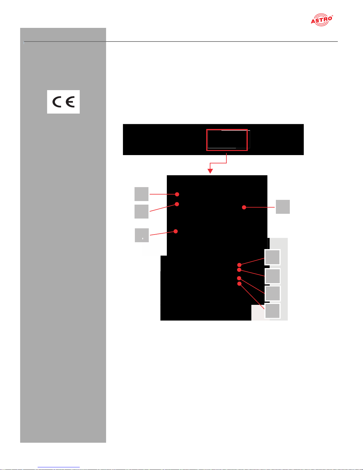
The delivery is comprised of the following parts:
U 144 DVB-S/S2 in IP streamer, including a display module and backplane
Operating manual
The U 144 plug-in module and the U 100 base unit feature a CE marking. This confirms that the products conform to the relevant EC directives and adhere to the requirements specified therein.
Figure 1, top:
U 144, installed in the U 100 base unit
(fitted with three plug-in modules)
Figure 1, middle:
U 144, front panel
[1] Screw for the front panel
[2] Display for management IP addresses,
data IP addresses, status messages, etc.
[3] Status display
[4] Control and data knob, menu switch
Figure I, bottom:
U 194, front panel after removal
[5] Release button, CI-slot 1
[6] Release button, CI-slot 2
[7] Release button, CI-slot 3
[8] Release button, CI-slot 4
Figure 1: U 144
1
2
3
5
6
7
8
4
Page 8

Device description
Oerating manual U 144 - Version 08-2016Apage 8
NOTE: Turning the data knob [4] (fig. 2, above) allows you to navigate through the
individual menu items in the U 144 display. Press the data knob to switch on the display.
The ASTRO logo will be the first display to appear following activation.
Turning the data knob clockwise allows to you access the individual displays:
Log messages: The last messages entered in the log book are displayed.
Interface settings: IP addresses of the network interface.
Software versions: The version of the plug-in module software currently installed is displayed.
Active alarms: The current error messages are displayed.
DVB-S2 module 1: The status of the four channels set is displayed.
CAM modules 1 - 4 The respective reception channel forwarded to the CAM module is displayed.
.
The different text colours refer to:
Red: Error (the corresponding display in the web interface log book is: “error”)
Yellow: Warning (the corresponding display in the web interface log book is: “warning”)
Purple: Critical error (the corresponding display in the web interface log book is: “critical / alert /
emergency”)
Light blue: Info (the corresponding display in the web interface log book is: “info”)
Light green: Notice (the corresponding display in the web interface log book is: “notice”)
Page 9
page 9
Connecting and installing the module
Oerating manual U 144 - Version 08-2016A
Connecting and installing the module
NOTE: The instructions for the base unit U 100 include a description of how to prepare
the base unit for installation.
Observe that you need to insert an SD memory card into the module prior to installation in the
base unit (see figure at left).
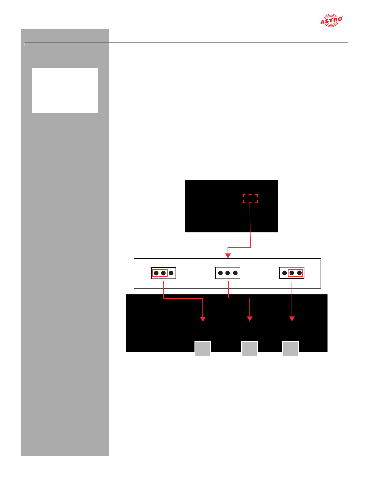
Coding and installing the backplane
A backplane is included with every U 1xx signal converter. This is used to establish a mechanical
connection between the signal converter and the base unit. Both the mains HF connections and the
network connections are connected to this
backplane. There is usually a temperature-controlled fan for cooling the signal converter on the
backplane. This can be replaced while the device is operating.
To ensure the position of the backplane, and therefore the position of the respective signal converter
in the U 100 base unit, is correct, you must plug a corresponding jumper into the circuit board on the
backplane. Proceed as described in the following.
[1] Left slot
[2] Middle slot
[3] Right slot
Figure 2: Coding the backplane by plugging in the jumper
1 2
3
Page 10
Connecting and installing the module
Oerating manual U 144 - Version 08-2016Apage 10
To prepare the backplane for installation, proceed as follows:
Plug the jumper into the installation position provided in accordance with figure 3
(page 8).
NOTE: A jumper which has not been correctly plugged into the corresponding installa-
tion position will result in incorrect LED displays on the front of the U 100 base unit (see section
“Device description”). Furthermore, the correct position cannot be displayed on the web
browser user interface.
[1, 2] Phillips-head screws
[3] Cable for signal supply
[4] Cable for power supply
You can now install the backplane in the base unit. To do so, proceed as follows:
Figure 3: Installing the backplane in the base unit
TASK
1. When the U 100 base unit is in its delivery state, the three installation slots for the backplanes are
covered by dummy plates (see figure 3, above). Start by removing the Phillips-head screws [1] and
[2] from the dummy plate at the required installation position (left, middle or right) and remove the
dummy plate.
2. You can now see the two connection cables for the selected slot (power supply and signal cable).
Connect the cables to the backplane as shown in figure 3 (above).
3. Now carefully insert the backplane into the slot of the U 100. Make sure the cables are not jammed.
You can push the backplane into the housing by applying light pressure.
R
BSULT:
The backplane is now connected and installed. Once installed, it should correspond to the figure at the
left.
1
2
3
4
Page 11
page 11
Connecting and installing the module
Oerating manual U 144 - Version 08-2016A
Inserting CI cards
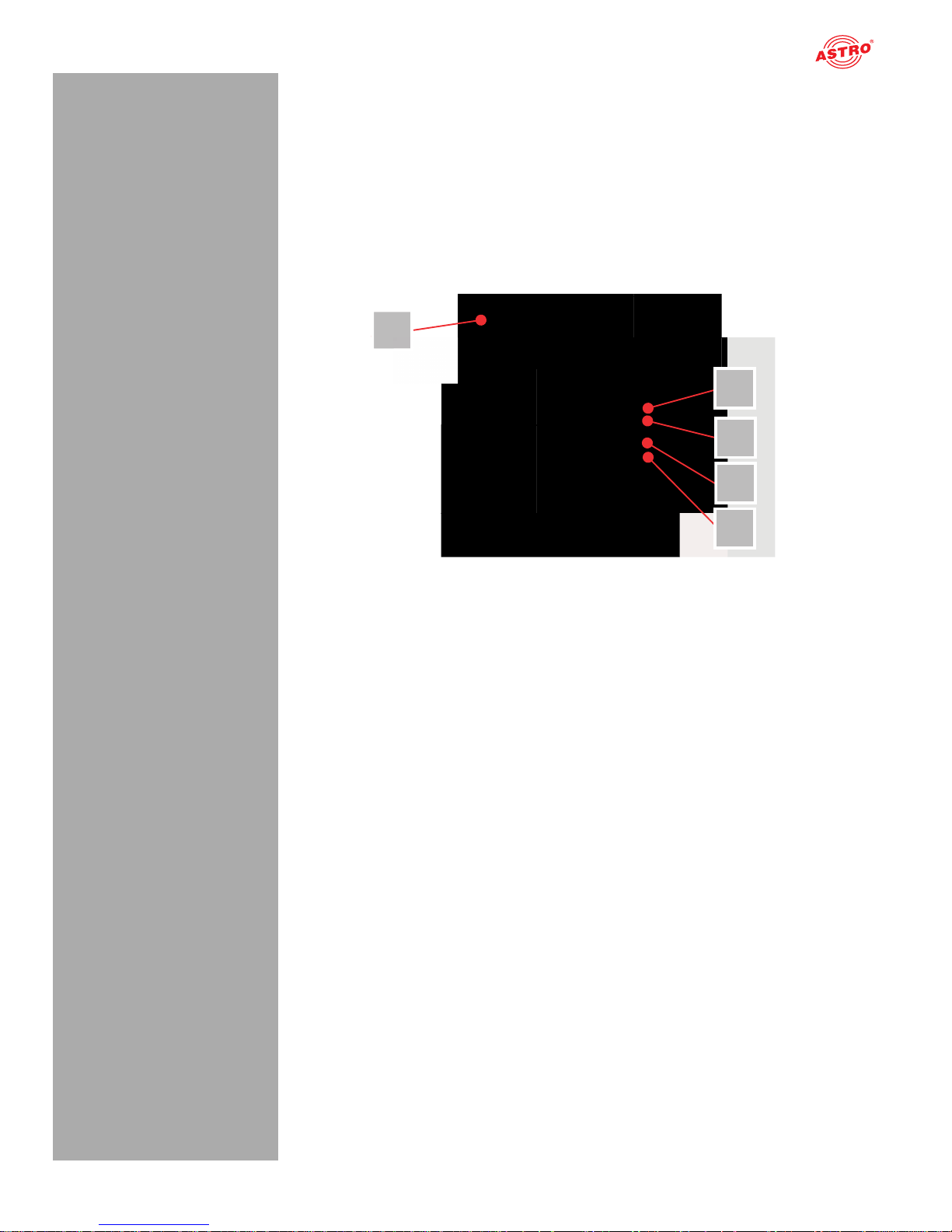
NOTE: CI cards can also be inserted and removed while the module is operating.
Before you can insert the CI cards, you must undo the screw connection [1] on the front panel of the U
194 (see fig. 5, below) and remove the front panel together with the display. The four CI slots and the
release buttons for ejecting the CI modules are visible.
Start by pushing each CI card into a CI module, and then push each module into one of the four CI slots
in the U 194.
To remove a CI module, press the corresponding eject button and remove the module.
[1] Screw for the front panel
[5] Release button, CI-slot 3
[6] Release button, CI-slot 4
[7] Release button, CI-slot 3
[8] Release button, CI-slot 4
Figure 4: CI slots
11
5
6
7
8
Page 12
Quick start - starting operation of the U 144
Oerating manual U 144 - Version 08-2016Apage 12
Quick start - starting operation of the U 144
Connecting the U 144 to a PC or laptop
To be able to configure the U 144, you now need to connect the network sockets (Management A or
Management B) on the backplane of the device (see figure at left) to your PC or laptop using a
network cable.
Once you have connected the base unit to the power supply, the U 144 will switch on automatically.
Once it has booted (approx. 90 seconds), the ASTRO logo initially appears in the display.
Turn the knob to the right of the display clockwise until the menu item “Interface settings” is displayed.
The two management IP addresses (Management A and Management B) for the device now appear
in the upper lines.
Make a note of the address of the management connection which you are using for your PC or laptop
to ensure you can enter this in the address line of your web browser later on.
NOTE: Please note that your PC or laptop must be in the same sub-network as the
U 144! The sub-network mask of the U 144 is set to 255.255.255.0 upon delivery. The PC or
laptop which is connected must therefore be assigned an IP address 192.168.1.x.
You can now start the configuration using the web browser user interface.
General information on the structure of the web browser interface
The configuration interface is divided into the following sub-areas:
Figure 5: Structure of the web browser interface
Status line (header) [1]: displays general information on the module.
SW: Software status
HW: Hardware version
Up: Runtime since the system was booted
Time: Date and time
Name, location, contact: corresponds to the settings which were made in the “User settings”
configuration area
Navigation menu [2]: displays the individual configuration areas which can be selected by
clicking the mouse. A detailed description of these areas can be found on the following pages of
this chapter.
Content area [3]: The respective configuration form – depending on the menu item selected – is
displayed here.
NOTE: The browser display is not updated automatically. Use the corresponding button
in the menu of your browser to update the display.
1
2
3
Page 13
page 13
Quick start - starting operation of the U 144
Oerating manual U 144 - Version 08-2016A
Logging in
To log in, enter the IP address of the U 144, which appears in the device display, in the address line of
the browser. The menu page “Status” will then appear. Select the item “Log in” from the navigation
menu at the left. The input mask for the log in should then appear (see figure 6, below). In delivery state,
you must use the following log-in data:
User name: “user” or “admin” (input without inverted commas)
Password: astro
Figure 6: Log in
After logging in, the start page of the U 144 with all relevant system information will appear. The navigation menu and the log-in status display will appear at the left.
Only one user can be logged into the user interface of the U 144 at a time. The current user is displayed
in the column at the left, below the menu.
The device status is indicated by a green or red circle. If a green circle is displayed, the device is operational. If the circle is red, then a fault has occurred.
A list of current errors is available under the menu item “Active alarms”.
NOTE: For reasons of security, you should change the access data valid upon delivery
(user name and password) to prevent unauthorised access!
The procedure is described in the section “Changing user data”.
Changing the IP address
NOTE: If you wish to change the IP address, then the settings on the PC must be changed
accordingly.
Start by changing the IP addresses for the management and the data port. To do so, click on the item
“Main” in the menu at the left. You will now see the following table in the content area:
Figure 7: Changing the IP address
You can enter the IP addresses for management ports A and B as well as for data ports A and B in the
“Address” line. Make sure that you activate the ports being used by activating the corresponding radio
button in the line “Active”.
To save your changes, click on the “Submit” button below the last table.
More information on configuring the IP address can be found in the section “Configuring IP interfaces,
IP management and base unit”.
Page 14

Quick start - starting operation of the U 144
Oerating manual U 144 - Version 08-2016Apage 14
The signal flow in the U 144
The overview on page 11 shows the possible signal paths for the U 144. The specific
signal flow can be divided into the following sub-areas:
One DVB-S2 signal from a satellite which can be preset can be fed in using each of the four F
sockets.
For each of the two front ends in the U 144, four reception channels (Ch 1.1 - 1.4) can be config-
ured. A preferred transponder can be selected from one of the four respective DVB-S2 reception
signals for the reception channel using a drop-down menu in the web user interface.
The signals from the four reception channels are forwarded via a multiplexer (CAM Mux) to CAM
modules 1 to 4 (the overview shows, as an example, the signal from reception channel 1 to CAM
1 and the signal from reception channel 3 to CAM 2; see the red line connecting them).
The signals from the reception channels are forwarded via a multiplexer (TX Mux) to one of the 8
IP transmitters (TX 1 - TX 8) in total (the overview shows, as an example, the signal from
Ch 1.2 to TX 5, the signal from Ch 1.3 to TX 7 and the signal from Ch 2.2 to TX 8; see the red line
connecting them).
Each of the output signals from the 8 IP transmitters can be forwarded to data port A and/or data
port B respectively.
Page 15
Quick start - starting operation of the U 144
page 15
Oerating manual U 144 - Version 08-2016A
Figure 8: The signal flow in the U 144
IP TX
1
2
3
4
5
6
7
8
TX Mux
Data A
Ethernet
Ethernet
Data B
Testgenerator
CAM 1 CAM 2
CAM 3 CAM 4
DVB-S2 RX
1.1
1.2
1.3
1.4
CAM Mux
Testgenerator
RF 2
RF 1
F-jack
F-jack
... 4 x; Input switch via software dropdown-list
RF 4
RF 3
F-jack
F-jack
Page 16
Quick start - starting operation of the U 144
Oerating manual U 144 - Version 08-2016Apage 16
Configuring DVB-S2 satellite receivers
Now start configuring a signal path in the U 144. Start by clicking on the item “Input settings” in the
menu in the web browser interface to have the reception settings for the four SAT inputs displayed.
You will now see the following table:
Figure 9: Selecting a reception signal
Select the required satellite (e.g. ASTRA, Eutelsat, etc.) from the “Satellite” drop-down menu. Select
the required polarisation level from the drop-down menu in the “Polarisation/Band” column.
Select a supply voltage for the LNB from the “Voltage” drop-down menu.
If you wish to use a 22 kHz pulse control, activate the radio button “on” in the 22 kHz Tone column.
To save your changes, click on the “Submit” button below the table.
Now click on the “Transponder” item in the main menu at the left to allocate, as an example, a transponder to the first reception channel (Ch 1.1).
Figure 10: Transponder settings
Select the preferred transponder for channel 1.1 from the drop-down menu.
To save your changes, click on the “Submit” button below the table.
Page 17
page 17
Quick start - starting operation of the U 144
Oerating manual U 144 - Version 08-2016A
Checking the transponder status
Now click on the menu item “Trsp. 1.1” in the menu at the left. You will now see the following overview:
Figure 10: Displaying the transponder status
The message “OK” should now appear in the “Status” line in the “Transponder 1.1 Setti ngs” table.
Now check the most important parameters in the table which follows, “Channel Status”.
Ensure that you check the values in the “Quality”, “Tuner Level” and “C/N” lines here.
Page 18
Quick start - starting operation of the U 144
Oerating manual U 144 - Version 08-2016Apage 18
Setting the signal routing to the CAM modules
Now insert the required CI module into the first slot of the U 164 if you have not already done so. Proceed as described in the section “Connecting and installing the module”.
Click on the item “CAM Mux” in the web browser interface menu. You will now see the following table:
Figure 11: Signal routing to the CAM modules
In the switch matrix, click on the radio button which connects the receiver DVB-S/S2 RX 1.1 to CAM
module 1.
To save your changes, click on the “Submit” button below the table.
More information on signal routing can be found in the section “Configuring signal paths using the
switch matrix”.
Now click on the item “CAM 1” in the menu at the left. (You may have to press the refresh button in your
browser several times to update the page.) You will now see the following table:
Figure 12: CAM settings
A list of the individual services which the module CAM 1 is receiving appears in the “Status” table. You
can select the service for decryption in the “Decryption Settings” table. To add a service, click on the
plus symbol in the right-hand column.
More information on decryption settings can be found in the section “Settin g the decrypti on”.
When decryption is successful, a text which is highlighted in green appears in the status column (example: see figure at left).
Page 19

page 19
Quick start - starting operation of the U 144
Oerating manual U 144 - Version 08-2016A
Setting the signal routing to the IP transmitters
You can now connect the reception signal to an IP transmitter. To do so, click on the item “TX 1..8
(MPTS)” in the web browser interface menu for configuration of one of the MPTS channels. You will
now see the following table:
Figure 13: Signal routing to the IP transmitters
In column „Source“ select a source from the dropdown list.
To save your changes, click on the “Submit” button below the table.
Configuring the IP transmitter
To complete the process, you should now configure and activate the IP transmitter. To do so, click on
the item “IP TX 1” in the web browser interface menu. You will now see the following table:
Figure 14: Configuring the IP transmitter
Enter the IP address and port of a reception device (e.g. for one of the signal converters from the U 1xx
series) in the line “Destination IP Port”.
In the table at the top, click on the radio button “on” to activate signal transmission to one of the data
ports A or B.
To save your changes, click on the “Submit” button below the table.
More information on setting the IP transmitters can be found in the section “IP TX menu”.
Page 20

Quick start - starting operation of the U 144
Oerating manual U 144 - Version 08-2016Apage 20
Checking the data transmission rate
Now click on the item “Statistics” in the menu at the left. You will now see the following overview:
Figure 15: IP transmitter statistics
A value > 0 should now appear for the data transmission rate in the line “Transmit” in the “Ethernet
bandwidth” table.
A corresponding value should appear in the line “Total transmit frames generated from IP TX 1” in the
“Ethernet frames” table.
More information about the values in the “Statistics” overview can be found in the section “Statistics
menu”.
Once you have successfully completed all the steps described, then the most important settings required to decrypt a data stream have been entered in the device.
To ensure error statuses entered in the log book are easy to follow, you should configure a time source.
This can be done under the menu item “Main” in the
“IP Management Settings” table (also see the section “Main Menu”).
Page 21

page 21
“Status” menu
Oerating manual U 144 - Version 08-2016A
“Status” menu
To have the current settings for the U 144 displayed, click on the Status item in the menu at the left.
You can now see the overview shown in figure 18:
Figure 16: Status display
The following tables are displayed:
Ethernet status
Configuration data and status of the Ethernet port
Figure 17: Status display - Ethernet
Page 22

“Status” menu
Oerating manual U 144 - Version 08-2016Apage 22
The values for the following parameters are d isplayed and configured here respectively in accordance
with the four connections on the backplane of the U 144 (Data A, Data B, Management A and Management B, see section “Device description”).
MAC: MAC address (display value)
Address: IP address (configurable)
Netmask: Net mask (configurable)
Gateway: Gateway IP address (configurable)
Mode: Ethernet mode (display value)
Transmit: Data transmission rate (display value)
Receive: Data reception rate (display value)
Status display of the IP transmitters:
Figure 19: Status display - IP TX channels
The values set for the following parameters are displayed in the table “IP TX Settings” for the four IP
transmitters – for port A and B respectively:
TX IP socket: Destination IP address/port
Encapsulation: Data encapsulation
FEC: Forward error correction
TSID/ONID: Transport stream ID / original network ID
Alias: Alias name
Details on the parameters can be found in the section “Menu IPTX”.
Page 23

page 23
“Status” menu
Oerating manual U 144 - Version 08-2016A
Status display on temperature, internal voltages and the power module:
Figure 20: Status display - Miscellaneous
The following, general parameters are displayed in the “Miscellaneous” table:
Temperature: Temperature display in °C for the mainboard, as well as DVB-S2 1 - 4 and 5 - 8.
Supply 1.2 V: 1.2 V supply voltage
Supply 1.8 V: 1.8 V supply voltage
Supply 2.5 V: 2.5 V supply voltage
Supply 3.3 V: 3.3 V supply voltage
Supply 5.2 V: 5.2 V supply voltage
Supply 13 V: 13 V supply voltage (mainboard only)
Fan: Fan rotation speed
Supply 1.0 V: 1.0 V supply voltage
Page 24

“Status” menu
Oerating manual U 144 - Version 08-2016Apage 24
Memory status:
Figure 21: Status display - System resources
Information on the internal resources of the operating system can be viewed in the “System resources”
table. No settings can be made here.
Page 25

page 25
“Main” menu
Oerating manual U 144 - Version 08-2016A
“Main” menu
This section explains how to enter general settings for the interfaces and the management of the U 168,
as well as for the U 100 base unit.
Click on the item “Main” in the menu at the left.
Setting the IP interfaces
You can configure IP interfaces and activate or deactivate them using the upper table (“IP interface settings”). The connection type is automatically identified and displayed by the U 168 (in this case: 1
GBit/s, full duplex).
NOTE: In order to make changes in this table, you must be logged in as the adminis-
trator.
Figure 22: Configuring IP interfaces
The following parameters are displayed, and can be configured:
MAC: MAC address of the respective interface
Active: Activate the radio button “on” to activate the interface. Activate the radio button “off” to
deactivate the interface.
Mode: Connection type (identified automatically)
Address: IP address
Subnet: Netmask
Broadcast: Broadcast address (calculated)
Gateway: Gateway IP (if available; otherwise, set this to 0.0.0.0)
NOTE: When programming the IP addresses, make sure the addresses have not already
been allocated within your network. Address conflicts result in network malfunctions. (Please
set unused parameters to 0.0.0.0.)
To save your changes, click on the “Submit” button below the last table.
Configuring management settings
You can configure the following management settings in the second table (“IP management settings”):
Figure 23: Configuring management settings
Page 26

“Main” menu
Oerating manual U 144 - Version 08-2016Apage 26
DNS: Enter a DNS server, if required, in the input fields.
SNTP server: You can enter one or two time servers here (SNTP protocol).
Time Source: “SNTP server” is set here as the default option.
To save your changes, click on the “Submit” button below the last table.
Configuring the base unit
You can enter settings for the U 100 base unit in the third table (“U 100 Rack settings”).
Figure 24: Configuring the U 100 base unit
The following parameters are displayed, and can be configured:
Base Address: Enter an address for the base unit being used here. If the
U 168 is managed using the U 100-C controller and several U 100 base units are being used, then
each base unit must be allocated an address of its own.
This setting only has to be entered for one module per base unit.
Slot Address: In accordance with the coding of the backplane of the U 144 performed previ-
ously (see section “Installing and connecting”), the address corresponding to the slot in the base
unit is displayed here.
Power Modules: Select the number of power modules being monitored from the drop-down
menu
To save your changes, click on the “Submit” button below the last table.
Page 27

page 27
“Main” menu
Oerating manual U 144 - Version 08-2016A
Saving and loading configurations / default and reboot
Figure 25: Saving and loading configurations
Changes to the configuration of the U 144 are written to the device by clicking the “Submit” button, and
are activated immediately. If you wish to save the current status to a separate memory, click on the
“Save 2nd” button (below the tables). This current status is then saved to the SD card in the U 168. By
clicking on the “Load 2nd” button, you can query this status again. How to save the configuration onto
the local computer or FTP server is explained in the section “Software update and configuration files”.
When you click the “Force Save” button, all settings are saved immediately. The time settings for automatically saving changes are then overridden.
Click on the “Default” button if you wish to restore the default settings.
ATTENTION: If you click the “Default” button, all settings except for the user and network
settings for the data and management ports are reset to the delivery state.
Click on the “Reboot” button to restart the unit with the last settings saved.
Page 28

“Input Settings” menu
Oerating manual U 144 - Version 08-2016Apage 28
“Input Settings” menu
To have the reception settings for the four SAT inputs of the U 144 displayed, click on the item “Input
settings” in the menu at the left.
LNB and DiSEqC settings
Settings for the supply unit used can be entered in the upper “Configuration” table.
Figure 26: “Configuration” table
The following parameters can be configured here:
LNC Type: Select the LNB type being used from the drop-down menu (Universal or Quattro
switch). If you use an LNB with a different LO frequency, select the item “LO = manual input”.
Voltage Vertical: Select the LNB voltage for vertical polarisation (this is used when the
“Voltage” parameter in the “Input Settings” table is set to “auto”).
Voltage Horizontal: Select the LNB voltage for horizontal polarisation (this is used when the
“Voltage” parameter in the “Input Settings” table is set to “auto”).
DiSEqC: If you are using a reception unit with a DiSEqC controller, activate the corresponding
radio button for the version supported here. If no DiSEqC
controller is being used, activate the radio button “off”.
If you change the activation or deactivation status of inputs or outputs in one of the two tables, then
click on the “Submit” button below the last table to save your changes. Click on “Reset form” to restore
the original settings.
Satellite settings
You can enter settings for selecting the satellite used for reception in the “Input Settings” table.
Figure 27: “Input Settings” table
Page 29

page 29
“Input Settings” menu
Oerating manual U 144 - Version 08-2016A
You can configure the following parameters for the four respective SAT inputs here:
Satellite: Select the required satellite (e.g. ASTRA, Eutelsat, etc.) from the drop-down menu
here.
Polarisation/Band: Select the required polarisation level from the drop-down menu.
Voltage: Select the required supply voltage.
22 kHz Tone: Select whether a 22 kHz pulse conversion should be activated. To do so, activate
the corresponding radio button. When you activate “Auto”, the 22 kHz tone is automatically activated for the high band.
Sensor: Measured LNB feed voltage/current
LNA Gain: amplification of low noise amplifier
If you change the activation or deactivation status of inputs or outputs in one of the two tables, then click
on the “Submit” button below the last table to save your changes. Click on “Reset form” to restore the
original settings.
Satellite settings
You can enter settings for selecting the satellite used for reception in the “Input Settings” table.
Figure 28: “Satellite DiSEqC Settings” table
You can enter DiSEqC settings for the individual satellites here. You can select the following parameters individually using the respective drop-down menu:
Port group 0 (Committed): Select one of the options “A”, “B”, “C” or “D” from the drop-down
menu here.
Port group 1 (Uncommitted): Select a value between 0 and 15 from the drop-down menu.
Port group 2 (Expansion): Select a value between 0 and 15 from the drop-down menu.
Port group 3 (Expansion): Select a value between 0 and 15 from the drop-down menu.
If you change the activation or deactivation status of inputs or outputs in one of the two tables, then click
on the “Submit” button below the last table to save your changes. Click on “Reset form” to restore the
original settings.
Page 30

“SAT RX” menu
Oerating manual U 144 - Version 08-2016Apage 30
“SAT RX” menu
To select the preferred transponder for the respective reception channels (Trsp. 1.1 - 1.4 and
Trsp. 2.1 - 2.4), click on the item “Transponder” in the menu at the left.
Selecting a transponder for a reception channel
You can select a transponder for each of the four reception channels in the “Transponder Settings” table.
Figure 29: “Transponder Settings” table
Select the preferred transponder from the drop-down menu in the “Transponder [Freq. - Input - TS-ID
- ON-ID]” column.
The items in the list are grouped according to the satellites selected in the “Input Settings” table.
If you change the activation or deactivation status of inputs or outputs in one of the two tables, then
click on the “Submit” button below the last table to save your changes. Click on “Reset form” to restore
the original settings.
Page 31

page 31
„Service Filter“ menu
Oerating manual U 144 - Version 08-2016A
„Service Filter“ menu
For transport streams TS 1.1 - TS 1.4 a service filter can be configured each to delete services from
the transport stream. Click on one of the items „TS 1.1 - TS 1.4“ in the Service Filter menu on the left
to show up the configuration tables.
Adjusting the setup for a service filter
In the first table „Service Filter Setup“ you can activate or deactiva te the service filter function for the
selected service filter by clicking on radio button „on“ or „off“.
Figure 30: Table „Service Filter Setup“
When the filter is activated, you can choose an appropriate bit rate in section „General Parameters“ by
typing the desired value into the input field. Please note, that the lowest possible bit rate depends on
the number of services that the transport stream contains. If the chosen bit rate is too low, some of the
services may not be transmitted properly.
If PIDs without referencing are desired to be deleted from the transport stream, click on the radio button
„drop“ or choose „pass“, if these PIDs are desired to remain in the transport stream.
In row „Filter Type“ you can choose if the services selected in the next table „Service Selection“ are
being deleted from the transport stream (radio button „drop“) or if only the selected services will remain
in the transport stream.
After making changes within the table, click on the „Submit“ button below the last table to store your
changes.Click on the „Reset Form“ button to restore the original settings.
Selecting services
In table „Service Selection“ you can choose services by selecting the desired service from the drop
down list in column „Select“. The click on the plus symbol to add the service.
Figure 31: Table „Service Selection“
Services, that are added to the selection are marked with a minus symbol in column „Action“. To delete
a previously selected service, simply click on the minus symbol of that service.
Page 32

„Service Filter“ menu
Oerating manual U 144 - Version 08-2016Apage 32
When handling longer service lists you can simply add all services to the list (click button „Add All“) or
delete all selected services at once (click button „Remove All“). Click the „Reset Form“ button to restore
the original settings.
In the next table „Status“ you can see an overview of all services with their curent status („drop“ or
„pass“).
Figure 32: Table „Status“
Page 33

page 33
“RX 1.1 - RX 1.4“ menu
Oerating manual U 144 - Version 08-2016A
“RX 1.1 - RX 1.4“ menu
To configure the transponders manually, start by selecting the item “Transponder” in the menu at the
left. Then select the option “manual” in the transponder drop-down menu in the “Transponder Settings”
table.
Now click on one of the menu items “Trsp. 1.1 - 1.4” in the menu at the left. You will see the following
table in the content area at the top:
Figure 30: “Transponder X.X Settings” table
The following settings can also be entered individually:
Input: To activate or deactivate the channel, select the corresponding radio button.
Transponder: Select the preferred reception system from the drop-down menu.
Manual Settings: Select the preferred reception frequency from the drop-down menu. If you
select the item “manual” from the list, you can enter the required value, in kHz, in the “manual freq.”
input field.
Frequency: Transponder frequency
Symbol Rate: Transponder symbol rate
TS-ID: Transport current ID
ON-ID: Original network ID
Click on the “Submit” button below the last table to save the changes.
Click on “Reset form” to restore the original settings.
In der next table „SAT RX Status“ you will find an overview of the reception parametes of the reception
channels chosen in the menu.
Figure 31: SAT RX X.X Status“
Page 34

“RX 1.1 - RX 1.4“ menu
Oerating manual U 144 - Version 08-2016Apage 34
Alias: labeling of the received transponder
Input: selection of the physical RF input (1-4)
Status: status of transponder
Standard: broadcast standard (DVB-S or DVB-S2)
Tuned IF-Frequency: intermediate frequency (in kHz)
TS-ID / ON-ID: transport stream ID / original network ID
Demod. Power: demodulation (in dBm)
Input Power: input sensitivity (in µV)
C/N: signal/noise ratio (in dB)
C/N Margin: limitation of signal/noise ratio (in dB)
BER: Bit Error Rate
Symbol Rate: symbol rate
BER: Bit Error Rate
Puncture Rate: puncturing rate
Modulation: modulation process
Rolloff: rolloff
Spectrum: spectrum
Page 35

page 35
“CAM Mux” menu
Oerating manual U 144 - Version 08-2016A
“CAM Mux” menu
You can configure the receiver routing to the four CAM modules using this menu item.
NOTE: An overview of the possible signal paths can be found in the “Quick start –
starting operation of the U 144” section.
Start by clicking on the menu item “CAM Mux” in the menu at the left. You will now see the following
table:
Figure 32: Output switch matrix “CAM Mux Settings”
You can forward the respective output signal from a reception channel to one of the CAM modules by
clicking on the corresponding radio button.
Furthermore, the output signal from each CAM module can be forwarded on to one of the other CAM
modules.
If no input signal is available, you can also forward the signal from the test generator (see “Test generator” section) to the respective CAM modules.
The transport stream ID, the network ID and the alias name for each source are displayed respectively
in the upper part of the table.
Click on the “Submit” button below the table to save the changes.
Click on “Reset form” to restore the original settings.
NOTE: The “Quick start – starting operation of the U 144” section includes a configu-
ration example.
Page 36

“CAM 1 - CAM 4” menu
Oerating manual U 144 - Version 08-2016Apage 36
“CAM 1 - CAM 4” menu
This section tells you how to make the decryption settings for the four CAM modules.
The procedure is described in the following.
To have the input screen for the module configuration displayed, click on one of the items “CAM1”,
“CAM2”, “CAM3” or “CAM4” in the menu at the left.
CAM module information
The respective name of the module as well as the current status is displayed in the upper table. If the
module is functioning properly, the message “running” appears. If a CAM module has not been installed, then the message reads “no CAM installed”. Other error messages are “CAM error temperature
too high” and “voltage error”.
Figure 32: CAM module information
Click on the “+” symbol in the left column to have an overview of the CA systems displayed.
If you click on the “Menu” button in the right column, the MM menu for the module opens.
Entering decryption settings
The second table allows you to add the service for decryption and – if preferred – to limit the decryption
to individual elements.
Figure 33: Selecting services for decryption
To add a service, start by selecting the service in the “Select” column, or enter the SIDs manually in
the input fields. Click on the “+” symbol in the right column. The service will now be added.
You can set different SIDs for the redundant sources of reception.
Details on the redundancy concept can be found in the section “IP RX menu”.
Depending on the active source, either Primary, Secondary or Tertiary is flagged as active.
.
Page 37

page 37
“CAM 1 - CAM 4” menu
Oerating manual U 144 - Version 08-2016A
NOTE: If you wish to delete a service from the list, then click on the red symbol in the
column at the right.
If you wish to select individual elementary streams, click on the pencil symbol to activate the service.
You can select whether the full service (“all”) or only individual elements (“selective”) should be decrypt-
ed in the “Elements” column. Click on the corresponding radio button to do so. If you select the option
“selective”, another table is expanded in which the individual elementary streams can be selected.
Figure 34: Selecting specific service elements
You can choose between the options “PID”, “Content” and “Stream Type” in the “Select by” column.
.
The “PID” options allows selection according to the elementary stream PID. Enter the required PID in
the respective input field manually (for the “Secondary” and “Tertiary” fields, see the section “RP PX”
menu.
The “Content” option allows selection according to the content of the elementary streams. A drop-down
menu with the following options appears in the “Value(s)” column:
Video: All video elementary streams are decrypted.
Audio: All audio elementary streams are decrypted.
Teletext: The elementary streams for all languages are decrypted.
Subtitling: When you select this option, the elementary streams for the subtitles are
decrypted.
Two input fields for language selection appear to the right of the drop-down menu, in which you can
enter the preferred language or an alternative language as an abbreviation.
The “Stream Type” option allows selection of the elementary streams according to DVB stream type.
Your changes are applied as soon as either the Plus button or the Tick button is clicked.
Click on “Reset form” to restore the original settings.
Page 38

“CAM 1 - CAM 4” menu
Oerating manual U 144 - Version 08-2016Apage 38
Status display
An overview of the decryption status is displayed in the third table (see figure 32,
below). The respective SID appears in the left column, with the middle column showing the selected
service and the current status of the decrypted PIDs appearing in the right column.
If no decryption occurs, then “no processing” appears.
Figure 35: Decryption status display
Services marked in bold type include at least one encrypted service.
Click on the “+” symbol in the left column to have the detailed settings for decryption displayed.
Figure 36: Status details display
The advanced view shows all the settings made in the “Decryption Settings” table (decrypted PIDs,
type, selected content, language). Furthermore, it shows whether the content is encrypted or unencrypted (“scrambled” or “free”).
The “Output” column shows whether the content of the output signal is unencrypted for the respective
PID. The “Status” column shows whether the PID is being decrypted (“descrambling” or “no processing”) or whether errors have occurred.
Page 39

page 39
“IP TX” menu
Oerating manual U 144 - Version 08-2016A
“IP TX” menu
To transmit a single service as an IP transport stream (SPTS) you can activate up to 504 SPTS channels. The configuration of the SPTS channels can be done via the menues IPTX 9...
Figure 37: “IP TX channel settings” table
Within the table „Modify IP TX Channels“ you can comfortably add or delete a desired number of channels in the SPTS list.
To add channels type in the desired number of channels into the input field „Number“ in row „Add SPTS
Channels“ and click on the plus symbol in column „Action“.
To delete a range of existing channels type in the desired channels in row „Remove SPTS Channels“
in „X-Y“ manner (e. g. 10-14 or the like). Then click on the minus symbol in column „Action“.
NOTE: Up to 504 SPTS channels can be used.
NOTE: It is also possible to add or delete channels via the individual menu of each SPTS
channel (TX 9..) - however you can add or delete only one single channel in one individual
procedure (see chapter „TX 9..).
Page 40

“TX 1..8 (MPTS)” menu
Oerating manual U 144 - Version 08-2016Apage 40
“TX 1..8 (MPTS)” menu
To configure the 8 MPTS channels, start by clicking, in the menu at the left, on the item “TX 1..8
(MPTS)”. The following table will then appear in the content area at the top:
Figure 38: Table 1 “IP TX settings (MPTS)”
Here you can select the desired program source for each channel in column „Source“ fom a dropdown
list. Each channel can be routed to one of the outputs A or B respectively to to both channels by clicking
the radiobutton „On“. Type in the IP port into the corresponding input fields.
Click on the „Submit“ button below the last table to store changes.
Click on the „Reset Form“ button to restore the original settings.
To configure one of the 8 MPTS channels click on one of the items TX1“, „TX 2“, „TX 3“ ... „TX 8“ in the
left column. You will then see the following table:
Figure 39: Table 1 „IP TX1 Channel Settings“
You can activate or deactivate forwarding of the selected IP output to ports A and B respectively by
clicking on the corresponding radio button. The MAC address is displayed for ports A and B respectively (“Destination MAC”).
You can enter one value for ports A and B respectively for the following parameters:
Transmit IP: Port: Enter the transmit IP address here.
Destination IP: Port: Enter the transmit IP address of a reception device here.
TOS/TTL: You can enter a value for the “Type of service” here (which is used for prioritising the
IP data packets). Enter a value for the validity period here (“Time to Live”).
VLAN (Set 0 to disable): Enter the address of a virtual local network here.
Page 41

page 41
“TX 1..8 (MPTS)” menu
Oerating manual U 144 - Version 08-2016A
Another table is shown in the following in which settings valid for data ports A and B can be entered.
Figure 40: Table 2 “IP TX1 channel settings”
TS Packets per Frame: The number of transport stream packets per frame; select a value
between 1 and 7 from the drop-down menu.
Protocol Encapsulation: Select either “RTP/UDP/IP” or “UDP/IP” as the protocol by clicking
the corresponding radio button.
FEC: Forward error correction
Select the number of columns from the first drop-down menu (“off” or a value between 1 and 20).
Select the number of rows from the second drop-down menu (“off” or a value between 4 and 20).
Select one of the two options, “Columns and rows” (Col + Rows) and “Column only” (Col only) from
the third drop-down menu.
Select one of the options “Plain”, or “Annex A” or “Annex B” respectively, from the fourth
drop-down menu.
Click on the “Submit” button below the last table to save the changes.
Click on “Reset form” to restore the original settings.
Page 42

Menü „ TX 9.. (SPTS)“
Oerating manual U 144 - Version 08-2016Apage 42
Menü „ TX 9.. (SPTS)“
The configuration of the SPTS channels is done - depending on the number of activated channels - via
one ore more menus „TX XX...YY“ with XX and YY > 8; e. g. „TX 9...24“. Click on the item „TX 9..24“.
in the main menu on the left. You will now see the following table:
Figure 41: Table 1 „IP TX Channel Settings (SPTS) 9..24“
In column „Source“ you can select the desired program source from a dropdown list. Each channel can
be routed to one of the outputs A or B respectively to to both channels by clicking the radiobutton „On“.
Type in the IP port into the corresponding input fields.
If desired you can delete the channels from the list by clicking on the minus symbol in column „Action“.
Click on the “Submit” button below the last table to save the changes.
Click on “Reset form” to restore the original settings.
To configure an SPTS channel in detail click on one of the items TX9“, „TX 10“, „TX 11“ ... „TX 24“ in
the left column. You will now see the following table:
Figure 42: Table 1 „IP TX Channel Settings“
Here you can activate or deactivate the routing of the selected IP output to ports A and B by clicking
on the corresponding radiobutton. For ports A and B the MAC address is displayed („Destination
MAC“).
For the following parameters you can type in a value for ports A and B:
Transmit IP: Port: Type in the transmission IP address.
Destination IP: Port: Type in the IP address of a reception unit.
TOS / TTL: Here you can type in a value for the „Type of Service“ (for priority of IP data pack-
ages). / Type in a value for the desired period of validity („Time to Live“)
VLAN (Set 0 to disable): Type in the address of a virtual local network.
NOTE: You can edit further SPTS channels via additional menus TX XX...YY in the
main menu on the left.
Page 43

page 43
“User Settings” menu
Oerating manual U 144 - Version 08-2016A
“User Settings” menu
Click on the menu item “User Settings” in the main menu at the left to have the corresponding input
mask displayed. The following input mask now appears:
Figure 43: User administration
You can create up to four users for the user interface of the U 168. The following three users have been
created as the default setting:
admin
user
controller
Users logged in as administrator can change all of the settings in the user interface. A number of settings are not accessible for other user groups (e.g. “IP Interface Settings” table in the “Main” menu).
The password for all three users is “astro”.
To change the access data for a user account, or to create a new one, enter the preferred user name
in the input field User name. Then enter the preferred password in the input field New Password, and
confirm it by typing it in the input field Retype New password again.
NOTE: A password must contain at least 5 characters. You can increase the minimum
requirements for passwords using the “Enforced Password Policy” option (see below).
To delete a user account, activate the corresponding checkbox Delete for the respective account in
the right column of the table.
The following settings can also be entered:
Timeout: You can enter a time for the automatic logout, in minutes, in this input field. If no more
inputs are made in the user interface, then automatic logout will occur once the time entered here
has elapsed.
The time remaining until automatic logout is displayed under the main menu, in the left column of
the user interface.
Name, Location, Contact: You can save a name for the system, the location and the contact
data for a person in these input fields. They are displayed in the status line.
Enforced Password Policy: Activate the checkbox when a password should have a
minimum of 8 characters, and include at least one lower-case letter, one upper-case letter, one
number and one special character.
Disallow anonymous access: Activate the checkbox when access to the content area
(tables) should only be possible after logging in.
Page 44

“User Settings” menu
Oerating manual U 144 - Version 08-2016Apage 44
IMPORTANT: All changes will only be applied after you have clicked on the “Submit”
button below the input mask. Click on the “Reset Form” button to delete the input values again.
Another table follows in which you can enter information for a RADIUS server. A licence is also required
for the RADIUS server function.
Figure 44: RADIUS administration
The following items of information can be entered individually:
RADIUS Server Address
RADIUS Server Port
RADIUS Shared Secret
RADIUS Server Retries
RADIUS Server Timeout
Enable RADIUS Log-in
NOTE: Users who have been configured on the device will be deactivated when a
RADIUS server is configured.
The RADIUS server must be configured accordingly. Users with the service type “Administrative” are the device administrators.
When you click the checkbox “Enable Radius login”, the RADIUS function is activated if the
RADIUS server is able to be reached. If this is not the case, the RADIUS function remains inactive, and the message “RADIUS logins have not been enabled because the connection check
failed” appears.
You can create a white list for all incoming IP data in a further table. In this case, only IP data will be
processed which come from a source entered in the white list.
Figure 45: White list administration
The following parameters can be specified for four IP sources respectively:
IP address
Netmask
Page 45

page 45
“SSL Settings” menu
Oerating manual U 144 - Version 08-2016A
“SSL Settings” menu
NOTE: A licence is required to use the SSL functions.
To enter SSL settings, click on the item “SSL Settings” in the main menu at the left.
There is a checkbox in the upper table “SSL Settings” which displays the redirection of HTTP requests
to the secure protocol HTTPS. After input of the licence, the checkbox is activated.
Figure 46: “SSL settings” table
In the following table, “Generate a CSR for this device”, individual items of information about the device
can be entered (“Certificate Signing Request”: address, organisation, etc.).
Figure 47: “Generate a CSR for this device” table
By clicking the “Download CSR” button, you can create a “Certificate Signing Request” with which your
CA can issue a certificate for the device. The input field “Private key in use” shows you whether the
device's own key, or the key which was entered and saved, is being used.
There is a third table, “Key and certificate settings”, below this.
Figure 48: “Key and certificate settings” table
“
Page 46

“SSL Settings” menu
Oerating manual U 144 - Version 08-2016Apage 46
This table allows you to:
Upload a device key (click on the “Search” button and select the preferred file; then click on the
“Upload key” button)
Delete an existing device key (click the “Clear key” button)
Upload a device certificate (click on the “Search” button and select the preferred file; then click on
the “Upload certificate” button)
Delete an existing device certificate (click the “Clear certificate” button)
Regenerate a device key and device certificate (click the “Regenerate” button)
The device administers two keys/pairs of certificates: “generated” and “user”. The following figure
shows which certificate and which key are used.
Figure 49: Using the certificates/keys
yes
yes
yes
User has deposited
certicate?
User key exists and ts
to certicate?
Use user key and
certicate
Use user certicate and
generated key
Use generated
crticate and key
Does user certicate
t to generated key?
no
no
no
Page 47

page 47
“Licensing” menu
Oerating manual U 144 - Version 08-2016A
“Licensing” menu
A number of functions of the U 168 (e.g. the TS Analyzer) can only be used after being enabled by
means of a licence key.
The licence key with the respective function can be purchased from ASTRO. You will receive a licence
key with which you can activate the functions usin g the web browser interface.
The format of the licence key is a text document (e.g. Lic001772000222.txt).
To activate the functions, start by clicking on the “Licensing” item in the menu at the left. The following
input mask now appears:
Figure 50: Enabling licences using the licence key
Now enter the licence key sent to you in the input field. The key or keys can be entered in the input
mask using “Copy & Paste”. Then click on the “Submit” button to transmit the text to the device. If the
licence is valid, this is confirmed with the message “License is valid”. An error message is displayed for
an invalid licence.
To order additional licences, the MAC address of the device must be specified.
You will find the MAC address on the web browser interface in the “Licensing” submenu (HWID). After
the MAC address has been submitted, the licence keys are generated by ASTRO are sent by e-mail or
on a CD.
Page 48

“Update/config.” menu
Oerating manual U 144 - Version 08-2016Apage 48
“Update/config.” menu
The menu item “Update/config.” allows you to update the firmware version of your device and upload
and download a variety of configuration data.
Firmware update from a local memory location
You will require an update archive for updating the device firmware. This can be downloaded from the
ASTRO firmware server (address: “http://astro-firmware.de/Headend-Firmware/u1xx”). The file name
of the archive required ends in “.up”. The name is comprised of the type designation of the device (U
168) and a four-digit version number.
Once the update archive has been downloaded, start by selecting the item “Update/config.” in the user
interface menu. The “Software update” table then appears in the content area at the top.
Figure 51: Firmware update
Now click on the “Search” button and select the path to the memory location of the update archive
downloaded beforehand.
Then click on the “Update and Reboot” button to start the update process. Please wait for the process
to be completed, and for the device to reboot.
Available Update Archives
The table table „Available Update Archives“ shows an overview update-archives already stored in the
module (up to ten). Users can have access to older software versions (Installation or deleting).
Figure 52: Firmware Update
Uploading and downloading configuration files
Figure 53: Loading/saving configuration files
Configuration files can be uploaded and downloaded.
To upload files, use the “Search” button to select the preferred file.
Then click on the “Upload” button to start the uploading process.
Page 49

page 49
“Update/config.” menu
Oerating manual U 144 - Version 08-2016A
The following files are available for download:
System settings (XML format)
Simply click on the corresponding file link to download the file.
Downloading configuration/status files
Figure 54: Loading status files
The following files are available for download:
Module info (XML format)
IP configuration (XML format)
System status (XML format)
System measurements (XML format)
Simply click on the corresponding file link to download the file.
Loading/saving firmware and configurations using (T)FTP
You can update firmware using a (T)FTP server using the table “Firmware update and configuration via
server” and load or save configuration files.
Figure 55: Loading/saving firmware updates and configurations using (T)FTP
To carry out the preferred action, start by selecting an action from the drop-down menu in the “Mode”
line. The action can only be carried out when the server path specified does actually exist. Furthermore,
any firewalls that have been installed must be configured in a way that allows (T)FTP communication.
Page 50

“Update/config.” menu
Oerating manual U 144 - Version 08-2016Apage 50
The following actions can be selected individually:
“Load config from server” action: A configuration stored on the (T)FTP server is transmitted to
the U 168 and can be activated immediately. The IP settings for the data and management interfaces on the device are not changed. The file “settings.xml” are written onto the U 168.
“Save config to server” action: The current configuration of the U 168 is written to the (T)FTP
server. The configuration includes the following files:
- “ip.xml” (IP settings for the data and management interfaces)
- “settings.xml” (all other settings, e.g. IP receiver and modulator settings)
- “user.xml” (user data)
“Update firmware from server” action: If you select this action, you must specify the preferred
software version under Version (a 4-character maximum applies). One the update is successful,
the message “Firmware update OK. Please reboot to use the new firmware version” appears.
“Load firmware from server” action: If you select this action, you must specify the preferred soft-
ware version under Version (a 4-character maximum applies). The software selected is written
to the SD memory card, but will not be unpacked.
“Unpack *.up archive” action: If you select this action, the update archive is unpacked and saved
to the SD memory card (specify the version number).
“Update firmware from SD card” action: If you select this action, the specified update archive on
the SD memory card is unpacked and programmed into the module (enter the version number).
“Overwrite backup firmware” action: The device software is saved in two partitions. The soft-
ware saved in the first partition is used for operating the module, while the second partition is used
to keep a backup copy ready for the event that the update process fails. As long as both partitions
are different, the information “Backup differs” will be displayed in the menu “Active Alarm Table”.
The current software is copied to the backup partition when this action is carried out.
Once you have selected an action, you can add any information still missing from the remaining lines
of the table:
(T)FTP Server address: Address of the server
Protocol: Activate the radio button “FTP” if you wish to use the more comprehensive FTP
protocol. Activate the radio button “TFTP” if you wish to use the more basic TFTP protocol.
FTP User name: This depends on the settings for the FTP server used (for astro-firmware.de
e.g. “anonymous”).
FTP Password: This depends on the settings for the FTP server used (for astro-firmware.de e.g.
“astro”).
Path: Path to the location where data are saved, or from where the data can be loaded. The path
must be specified in relation to the root directory of the FTP server, and must always begin with a
“/” and end with a “/” as well (enter without quotation marks).
Version: Enter the version number of the software which you wish to download or save here.
NOTE: If the update is carried out using the TFTP protocol, then filling in the input
fields “FTP User name” and “FTP Password” is not necessary.
Page 51

page 51
“System Log” menu
Oerating manual U 144 - Version 08-2016A
“System Log” menu
To have the system log displayed, click on “System log” in the menu at the left. The following overview
will now appear:
Figure 56: System log
You can check or configure the following parameters individually:
System log settings
Figure 57: Filter settings for the system log display
You can activate or deactivate filters for displaying the log entries here. To have messages
from the corresponding category displayed, activate the checkbox allocated to the category.
NOTE: You can connect to higher-level management systems using the “Syslog” and
“SNMP” parameters.
Page 52

“System Log” menu
Oerating manual U 144 - Version 08-2016Apage 52
Management Information Base (MIB)
The SNMP MIBs available are stored on the device and can be downloaded by using the download link
below the table “System Log Settings”.
System log
Figure 58: Logfiles
Click on the “Refresh” button to update the system log display. The entries in the system log are sorted
chronologically according to the time at which the event occurred.
If you do not wish for the existing entries to be displayed after a refresh, activate the checkbox “Checkbox to clear log on refresh”. Once the checkbox has been activated, after a refresh, the process of deleting the old log entries is listed as the first entry (specified the user account and the current time upon
deletion).
You can also download the following logfiles:
System log (CSV format)
Debug log (CSV format)
NOTE: You can also download a complete archive of log files plus the complete device
configuration by clicking on the link „To retrieve an archive of SUPPORT FILES click
here:“.You will need the device configuration in case of support inquiries. The name of the file
is put together by the name of the device and the last four numbers of the MAC address (e. g.
U1xx_0218f1_support-files.tar).
Downloading log files
Figure 59: Downloading log files
A maximum of 2,500 lines is displayed in the “Log files” table. The complete log file can be downloaded
from the “Download Log Files” table by clicking on the file name XX.csv.
Page 53

page 53
“Alarm severities” menu
Oerating manual U 144 - Version 08-2016A
“Alarm severities” menu
You can change the alarm settings for diverse parameters or deactivate the alarm display for a parameter, when preferred. To do so, click on the item “Alarm Severities” in the menu at the left. A set of tables
for different parameter groups then appears:
Figure 60: Alarm Severities
The preset options for the alarm messages are identified by a green frame. Retaining these settings is
recommended.
Page 54

“Active alarms” menu
Oerating manual U 144 - Version 08-2016Apage 54
“Active alarms” menu
To have the “Active Alarm” table displayed, click on the corresponding item in the menu at the left. The
following table now appears:
Figure 61: Active alarm table
The table provides information about error messages currently active. The “Message” column shows
the error message in plain text.
NOTE: You can also access the “Active Alarm Table” by clicking the red point in the
status line in the upper section of the user interface.
Page 55

page 55
“Statistics” menu
Oerating manual U 144 - Version 08-2016A
“Statistics” menu
To retrieve data transmission statistics for the U 168, click on the “Statistics” item in the menu at the
left. All statistics relevant to the operation of the device and which can be used for analysis are displayed here. The following tables are displayed individually:
Ethernet bandwidth
Figure 62: Ethernet bandwidth
The transmission rates for sending (transmit) and reception (receive) are specified for the respective
interfaces Management A, Management B, Data A and Data B.
Ethernet frames
Figure 63: Ethernet frames
The following parameters are displayed for the interfaces Data A and Data B, in this order:
The number of IP frames transmitted to the processor is specified in the first three lines of the
table.
Number of defective frames.
Number of frames which could not be allocated.
Number of frames which could not be allocated due to exceeding the total buffer depth.
The number of frames transmitted per transport stream in total or per second is displayed in the
following lines for each IP transmitter.
Page 56

“Statistics” menu
Oerating manual U 144 - Version 08-2016Apage 56
Ethernet TX
Figure 64: Ethernet TX
In reference to forward error correction, the smallest number of free FEC buffers measured at all is displayed in the first line.
The total number of FEC buffers is displayed in the second line.
Page 57

page 57
“Network” menu
Oerating manual U 144 - Version 08-2016A
“Network” menu
To have the network settings displayed, click on “Network” in the menu at the left. The following overview will now appear:
Figure 65: Network settings
The detailed interface statistic properties which are displayed are for information purposes only, and
are used to describe the network. They could be useful for customer service in the event of a fault.
“Devices” menu
To have an overview of the local data memory in the device displayed, click on the item “Devices” in
the menu at the left. Among other things, the total memory capacity, the capacity of the unused
memory, and the files saved are displayed.
Page 58

Troubleshooting
Oerating manual U 144 - Version 08-2016Apage 58
Troubleshooting
If the device is not functioning correctly, please perform the following checks:
Check whether the device is connected to the required grid voltage (230 V~, 50 Hz for the U 100
base unit, and 48 V for the U 100-48 base unit).
Check whether the signal cable is connected correctly, and that there are no breaks or short
circuits in the connectors.
If the problem cannot be resolved, pl ease contact the ASTRO customer service.
Maintenance and repair
The device must not be opened other than for repair purposes. Repairs may only be carried out at the
factory or at workshops, or by persons, authorised by ASTRO Strobel GmbH.
Read carefully: EN 60728-11 Safety requirements: No service work during thunderstorms.
NOTE: In the event of repairs, the DIN VDE regulations 0701 - 0702, where applicable,
must be observed, and priority must be given to the relevant data requirements in DIN EN
60950-1. You must disconnect the power plug before opening the device!
Service tasks
The following tasks, which involve the removal of screw connections, can be performed by appropriately instructed service personnel: Removal and installation of signal converters
(e.g. U 144) and power modules, even when the U 100 is operating.
Replacing power modules
After removing the screws from the cover of the power module chamber (ASTRO logo), the power
modules can be pulled forwards by hand using the mounting tab. When installing power modules, do
not touch the fan or fan grille and only use the mounting tab affixed to the power module.
When the tasks are complete, the cover of the power module chamber must be replaced. Continuous
operation of the device is not permitted without this cover.
ATTENTION: Never reach into the power module division of the U 100-230 base unit, or
insert objects into it.
NOTE: The U 100-230 base unit must only be operated with the original power
module(s)!
Replacing converter modules
Converter modules can be pulled out to the front after removing the safety screw in the fro nt covers
(see section “Connecting and installing the module”)
Page 59

page 59
Technical data
Oerating manual U 144 - Version 08-2016A
Technical data
Type U 144
Order number 380 144
EAN-Code
4026187170745
Number of DVB-S2 input signals
4
Number of DVB-S2 transponders
4
Number of IP output streams
4 + 4 MPTS, 504 SPTS (SPTS license afforded)
Interfaces
Management 2 x 100 Base-T Ethernet (RJ 45)
Data
2 x 1000 Base-T Ethernet (RJ 45)
Protocols
IEEE802.3 Ethernet, RTP, ARP, IPv4, TCP/UDP, HTTP, SNTP, IGMPv3
Transportstream Encapsulation
Protocols UDP, UDP / RTP, 1-7 packets, FEC
Packet length
Bytes 188 / 204
DVB-S demodulator
DVB-S modulation QPSK; 8PSK
Input frequency range
[MHz] 950 - 2150
Input level
[dBμV] 40 - 80
SAT-IF input
[Ω] 75, F-jack
Reflection loss
[dB] ≥ 10
Input symbol rate
[MS/s] max. 45,0 (depends on DVB-S2 Modulation)
DVB-S Roll-off-factors
0,20;0,25;0,35
DVB-S LDPC
1/2; 1/3; ¼; 2/3; 2/5; 3/5; 4/5; 5/6; 8/9; 9/10 (depends on DVB-S2 Modulation)
Viterbi decoding
(according DVB standard)
1/2; 2/3; 3/4; 5/6; 7/8; automatically / manually
DiSEqC Control
CI interfaces
CI slots 4 x (front access)
Supported modules
excerpt (others on
request)
Alphacrypt, Aston Conax, Dreamcrypt, Entavio CAM, GkWare BISS CAM, Homecast CAM,
ICECrypt, Ideto Access, Kid CAM, Mascom Cryptoworks, Matrix CAM, Mediaguard Canal Digitaal,
Nagravision, Oasis CAM, PCMCIA CAm, Premiere, Worldcam, TechniCam Beta2, Technicrypt,
Connectors 4 x PCMCIA
RF inputs
Connectors Ω 75, 4 x F-jack
Common data
Current consumption at 48 V mA 530
Power consumption at 36 - 60 V
W 25
Input voltage
V 36 - 60
Dimensions
1 HU, 19 inch
Ambient temperature
°C 0 … +45
Page 60

Oerating manual U 144 - Version 08-2016A
82 313 400 02EN
© 2016 ASTRO
Subject to change.
Change management and copyright:
This document contains information protected by copyright. It is prohibited to
photocopy, duplicate, translate or store on data storage media this document,
either partially or in full, without prior agreement of the ASTRO company.
These operating instructions have been written by:
ASTRO Strobel Kommunikationssysteme GmbH
Olefant 1-3, D-51427 Bergisch Gladbach (Bensberg)
Tel.: 02204/405-0, Fax: 02204/405-10
eMail: kontakt@astro.kom.de
Internet: www.astro-kom.de
All the information contained in this document has been checked in good faith.
The ASTRO company cannot be held liable for any damage or injury arising in
connection with the use of these operating instructions.
 Loading...