

Page 1

Portable signal generator programming software
SP-8848
Instruction Manual
Ver.2.6
Page 2

Page 3

Portable signal generator
programming software
SP-8848
Instruction Manual
2007.2
Ver.2.6
ASTRODESIGN,Inc
Page 4

Page 5

CCOONNTTEENNTTS
Chapter 1 About the SP-8848 .........................................................................................................................................1
1.1. General....................................................................................................................................................................1
1.2. Features...................................................................................................................................................................1
1.2.1. Software program compatible with Windows ....................................................................................................1
1.2.2. Simple data management functions with a high degree of freedom..................................................................1
1.3. Software installation.................................................................................................................................................1
1.3.1. Installing the SP-8848.......................................................................................................................................1
1.3.2. Installing the USB driver ...................................................................................................................................3
1.3.3. Uninstallation method .......................................................................................................................................3
1.3.4. Directories and files ..........................................................................................................................................4
1.3.5. Other files .........................................................................................................................................................5
1.3.6. Registration of Registry.....................................................................................................................................6
1.3.7. Usage as Multiple Users...................................................................................................................................6
S
Chapter 2
2.1. General....................................................................................................................................................................9
2.2. Starting up VGBase..................................................................................................................................................9
2.3. Closing VGBase..................................................................................................................................................... 11
2.4. Configuration settings ............................................................................................................................................11
2.4.1. Startup method................................................................................................................................................11
2.4.2. Window screen and description......................................................................................................................11
2.5. Creating and editing the program data...................................................................................................................16
2.5.1. Startup method................................................................................................................................................16
2.5.2. Window screens and description ....................................................................................................................16
2.6. Creating and editing the user characters ...............................................................................................................58
2.6.1. Startup method................................................................................................................................................58
2.6.2. Window screen and description......................................................................................................................58
2.6.3. Operation methods .........................................................................................................................................59
2.7. Creating and editing the group data.......................................................................................................................61
2.7.1. Startup method................................................................................................................................................61
2.7.2. Window screen and description......................................................................................................................61
Operation........................................................................................................................................................9
2.7.3. Operation methods .........................................................................................................................................62
2.8. Creating and editing the auto display data............................................................................................................. 64
2.8.1. Startup method................................................................................................................................................64
2.8.2. Window screen and description......................................................................................................................64
2.8.3. Operation methods .........................................................................................................................................65
2.9. Converting the image data.....................................................................................................................................67
2.9.1. Startup method................................................................................................................................................67
i
Page 6

2.9.2. Window screen and description......................................................................................................................67
2.9.3. Operation methods .........................................................................................................................................68
2.10. Creating and editing the optional patterns............................................................................................................ 69
2.10.1. Startup method..............................................................................................................................................69
2.10.2. Window screen and description.................................................................................................................... 69
2.10.3. Operation methods .......................................................................................................................................72
2.10.4. Convert to 256-color VBM file....................................................................................................................... 74
2.11. Monitoring and changing the IP/Gateway address............................................................................................... 76
2.11.1. Startup method..............................................................................................................................................76
2.11.2. Window screen and description .................................................................................................................... 76
2.11.3. Operation methods........................................................................................................................................77
2.12. Selecting and editing the layout data files............................................................................................................ 78
2.12.1. Startup method..............................................................................................................................................78
2.12.2. Window screen and description (Layout Edit)...............................................................................................79
2.12.3. Operation methods (Layout Edit)..................................................................................................................85
2.13. Setting the port number and IP address...............................................................................................................87
2.13.1. Startup method..............................................................................................................................................87
2.13.2. Window screen and description.................................................................................................................... 87
2.13.3. Operation methods .......................................................................................................................................88
2.13.4. General IP address classes..........................................................................................................................88
2.14. Color difference coefficient data editing program.................................................................................................89
2.14.1. Startup method..............................................................................................................................................89
2.14.2. Window screen and description.................................................................................................................... 89
2.14.3. Operation methods .......................................................................................................................................90
2.14.4. Menus...........................................................................................................................................................91
2.15. Creating and editing the DDC data ......................................................................................................................92
2.15.1. Startup method..............................................................................................................................................92
2.15.2. Window screen and description.................................................................................................................... 92
2.15.3. peration methods..........................................................................................................................................94
2.15.4. Menus...........................................................................................................................................................96
2.15.5. Block operations ...........................................................................................................................................97
2.16. Cursor tool program.............................................................................................................................................98
2.16.1. Startup method..............................................................................................................................................98
2.16.2. Window screen and description.................................................................................................................... 98
2.16.3. Operation method....................................................................................................................................... 100
2.16.4. Menus.........................................................................................................................................................101
2.17. All data copy tool................................................................................................................................................102
2.17.1. Startup method............................................................................................................................................102
2.17.2. WINDOW SCREENS AND DESCRIPTION................................................................................................102
2.17.3. OPERATION...............................................................................................................................................103
ii
Page 7

2.18. ClosedCaption/V-chip data transmission tool..................................................................................................... 105
2.18.1.Startup method.............................................................................................................................................105
2.18.2. Window screen displays and descriptions .................................................................................................. 105
2.18.3. Operation method....................................................................................................................................... 113
Chapter 3
3.1. 10bit Image data ..................................................................................................................................................115
Chapter 4
10bit Image data.........................................................................................................................................115
Error message reference............................................................................................................................117
iii
Page 8
Forew Word
Thank you for purchasing the programmable video signal generator.
This manual provides details on how to use the SP-8848 software program to edit, create, send and receive data
used for the programmable video signal generator (hereafter abbreviated to "VG"). (The figures and diagrams
referred to in this manual show what applies when the VG-848 has been connected, and there may be
differences when connections are made with another VG. Refer to the help provided for each editing program.
The basic operating methods are the same no matter which model VG has been connected.)
This manual describes how to use the SP-8848. For details on specific setting items, settings or other such
aspects, refer to the SP-8848 help or the instruction manual of the VG concerned.
After reading through this manual, keep it in a safe place for future reference.
SAFETY PRECAUTIONS
WARNING
Concerning foreign matter
● Do not spill liquids onto the product or drop inflammable objects or metal parts onto it. Use under these
conditions may cause a fire, electrical shock or malfunctioning.
CAUTION
Concerning the installation and operating locations
● Install this product in a stable place.
● Before installing the product, be absolutely sure to turn off the power of the computer and unplug its power
cable.
Concerning impact
● This is a precision piece of equipment and, as such, subjecting it to impact may cause malfunctioning. Take
special care when moving the product.
iv
Page 9
About the SP-8848
1
1
1.1. General
The SP-8848 is an application software program for operating the VG-848, and it is designed to run in a Windows
environment. It enables the statuses of the VG-848 to be captured and its settings to be changed. It can also create
data and execute the data which has been created.
All operations are conducted at the personal computer, and the data created can be stored in the computer as files.
1.2. Features
1.2.1. Software program compatible with Windows
This program enables data to be edited and executed in a Windows environment.
1.2.2. Simple data management functions with a high degree of freedom
Timing data and pattern data can be organized separately in their own files. Data management can easily be exercised
by such features as the list display, sort function and naming function.
1.3. Software installation
This section describes how to install the files which are used for operating the SP-8848 in a Windows environment.
These instructions apply to the installation which involves the use of the following disk.
SP-8488 installation CD, Windows edition
1.3.1. Installing the SP-8848
(1) Place the SP-8848 installation CD in the CD drive, and in Windows select [Start] → [Settings] → [Control Panel] →
[Add/Remove Programs] → [Install]. The installer now starts up, and the setup begins.
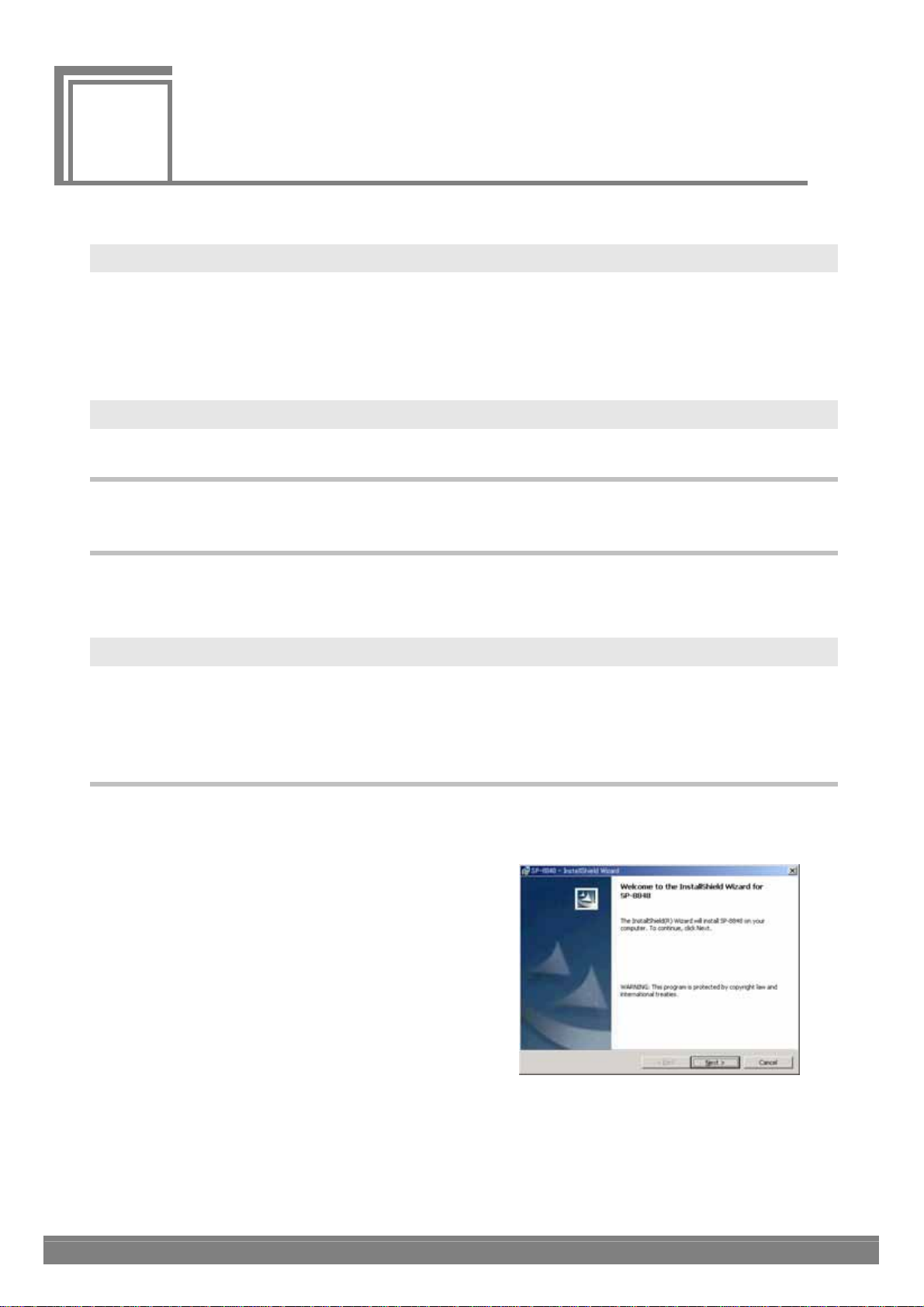
(2) The "Welcome" dialog screen is the first to appear. When the
[Next] button is clicked, the setup advances to the next step;
conversely, when the [Back] button is clicked, it returns to the
previous step. The setup is aborted by pressing the [Cancel]
button.
Click the [Next] button.
1
Page 10
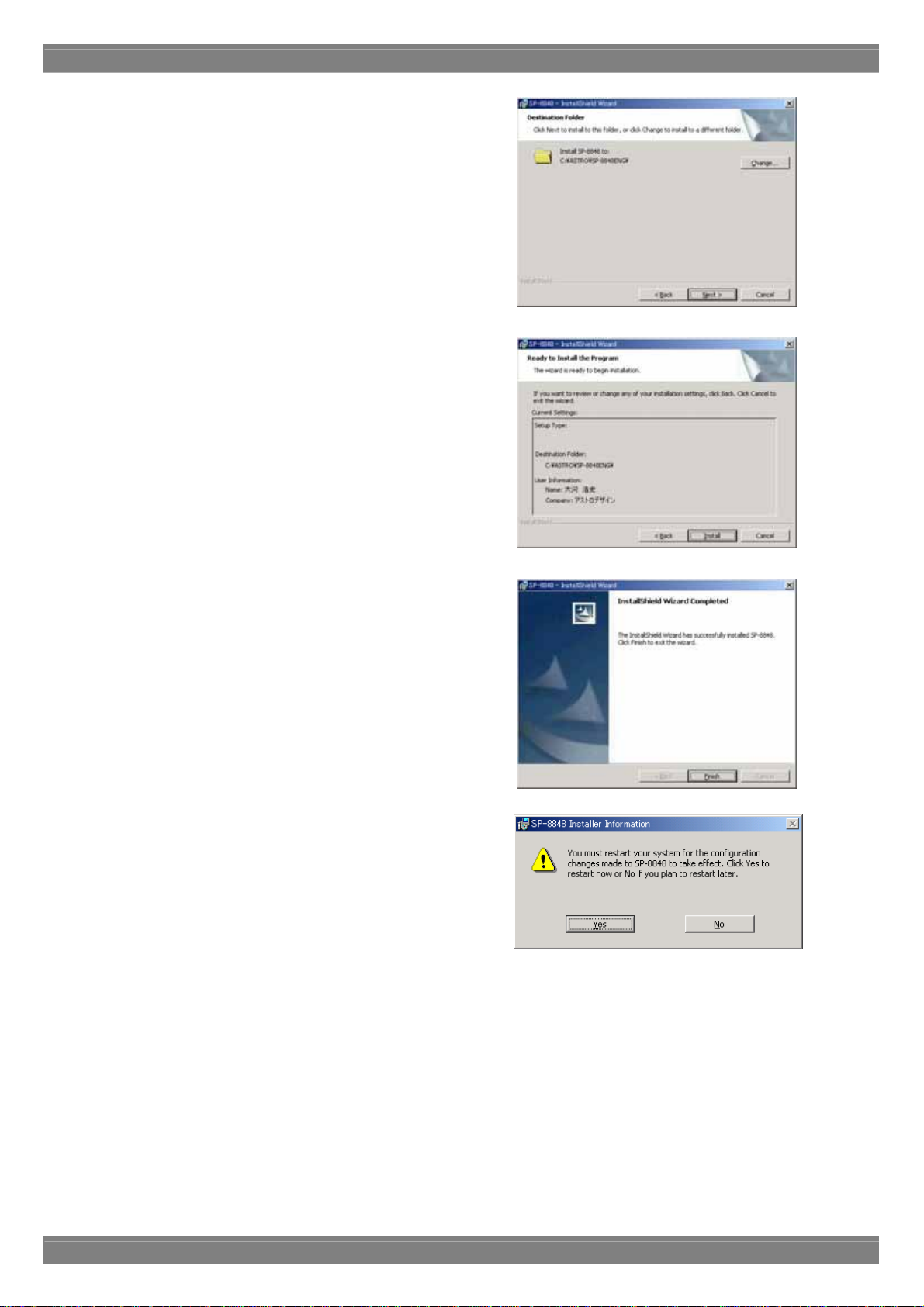
(3) On the "Select installation destination" dialog screen, select the
directory into which the SP-8848 is to be copied. As the default, the
"ASTRO¥SP-8848" directory is created in the C: drive root
directory, and the files are copied into it. The copy destination
directory can be changed to any directory specified by the user.
Click the [Browse] button and set the directory.
(4) Select the [Install] button. The file installation dialog screen now
appears, and installation begins.
(5) The setup is now completed. Press the [Finish] button.
(6) The user is now prompted to restart the PC. Be absolutely sure
to select [Yes].
(7) The installation is now completed. In Windows, select [Start] → [Programs] → [SP-8848] → [Guide Help] and read
through the guide help. Then select [Start] → [Programs] → [SP-8848] → [VGBase] to start up [VGBase].
2
Page 11
Chapter 1 About the SP-8848
1.3.2. Installing the USB driver
(1) When the system is connected with the VG for the first time, it recognizes the VG, and the [Add New Hardware
Wizard] dialog box appears. Select the [Next] button.
(2) Select [Search for optimal driver for device in use (recommended)] as the search method, and select the
[Next] button.
(3) Place the SP-8848 installation CD in the CD drive, check [Specify search location], specify CD drive
and select the [Next] button.
(4) Check that "VgUsb.sys" has been found, and then select the [Next] button. Installation now begins.
(5) For the remaining steps, follow the on-screen directions.
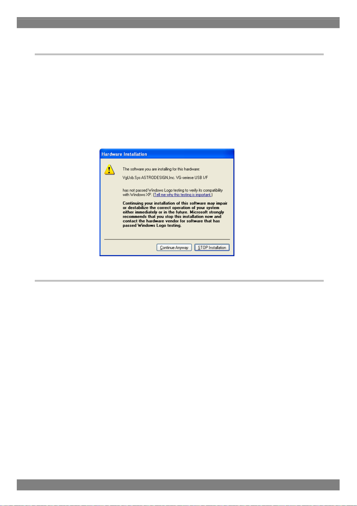
*When installing the driver in Windows XP, the following dialog box appears referring to the fact that Microsoft
has not officially certified its use. Press the [Continue] button.
1.3.3. Uninstallation method
In Windows, select [Start] → [Settings] → [Control Panel] → [Add/Remove Programs], and delete the software by
following the on-screen directions.
During this process, the user will be asked whether to delete "VGPIO.vxd" which has been installed in the Windows
system directory. Leave it if it is required. However, if the software is to be re-installed, the files and registry settings
must be deleted by uninstalling them before proceeding. The data files in the VGInt directory and UserChar directory
are read-only files and, as such, they are not deleted by uninstallation. Delete them separately. Similarly, if the USB
driver has been installed, it will not be deleted by uninstallation either, so delete it separately.
3
Page 12
1.3.4. Directories and files
The directory and files listed below are created by the installation of the software.
Specified directory (default: C:¥ASTRO¥SP-8848)
Data (data files used by the data editing programs)
(*.lot)
Sample.lot
AutoDispt
(*.adp)
Sample.adp
Group
(*.grp)
Sample1.grp,Sample2.grp
Image
(*.vbm)
usagi.vbm
XGA.vbm
SXGA.vbm
UXGA.vbm
1080_10bit.vbm
(*.bmp)
usagi.bmp
XGA.bmp
SXGA.bmp
UXGA.bmp
OptPtn
(*.mc)
g1_test.mc/g8_test.mc/window.mc/ptn_test.mc/256_col.mc/CbarGray.mc/IMG1.m
c/Crosst90.mc/CheckWin.mc/10_step.mc/cs_cr_ch.mc/cs_cr_gr.mc/DispAdj.mc/G
rayCirc.mc/RGBW_bar.mc/smpte271.mc/
(*.mo)
g1_test.mo/g8_test.mo/window.mo/ptn_test.mo/256_col.mo/CbarGray.mo/IMG1.
mo/Crosst90.mo/CheckWin.mo/10_step.mo/cs_cr_ch.mo/cs_cr_gr.mo/DispAdj.mo
/GrayCirc.mo/RGBW_bar.mo/smpte271.mo
Program
(*.prg)
SVGA.prg/CGA.prg/EGA.prg/PGA.prg/XGA.prg/UXGA.prg/VGA1.prg/VGA2.pr
g/VGA3.prg/XGA.prg
Temp
UserChar
(*.uch)
VGIntF0.uch - VGIntF7.uch
VGInt
(*.prg)
VGInt850.prg - VGInt999.prg
4
Page 13

Chapter 1 About the SP-8848
Exe (executable files of SP-8848)
(*.exe)
ADEdit.exe/CharEdit.exe/CnfgEdit.exe/GrpEdit.exe/LpEdit.exe/OptEdit.exe/PrgEdit.
exe/
VbmCvt.exe/VGBase.exe/VGManage.exe/CDCEdit.exe/CurTool.exe/Monitor.exe/VersionUp.e
xe/
(*.dll)
CmdDll.dll/GuiCmd.dll/ADDll.dll/CharFile.dll/CVSBMP.dll/GrpSetDll.dll/Layout.dl
l/LimitDll.dll/OptPtnFile.dll/PrgFiles.dll/RegDll.dll/TransDll.dll/TransUsb.dll/DDCE
dit.dll/DDCFile.dll/CDCFile.dll/ImgCom3.dll/imged32.dll/ImgEtc3.dll/ImgFile3.dll/I
mgTiff3.dll/ImgDsp3.dll/IpDlg.dll/
(*.msg)
SP_VG.msg/SPErr.msg/VGErr.msg/
OptDoc (text describing how to create the optional patterns)
make_OPT.txt
Help (help files)
(*.hlp)
ADEdit.hlp/GrpEdit.hlp/PrgEdit.hlp/CnfgEdit.hlp/CharEdit.hlp/VbmCvt.hlp/VGBase
.hlp/LpEdit.hlp/OptEdit.hlp/make_opt.hlp/VgManage.hlp/Vgerrmsg.hlp/Guide.hlp/D
DCEdit.hlp/CDCEdit.hlp/CurTool.hlp/VerUP.hlp/
(*.CNT)
ADEdit.CNT/GrpEdit.CNT/PrgEdit.CNT/CnfgEdit.CNT/CharEdit.CNT/VbmCvt.CN
T/VGBase.CNT/OptEdit.CNT/make_opt.CNT/VgManage.CNT/Guide.CNT/DDCEdi
t.CNT/CDCEdit.CNT/CurTool.CNT/VerUP.CNT/
1.3.5. Other files
File copied into the [¥Windows¥System] directory by the software installation
VGPIO.VXD
File copied into the [¥Windows¥System32¥Driver] directory by the USB driver installation
VGUSB.SYS
File copied into the [¥Windows¥Inf] directory by the USB driver installation
VGUGB.INF
5
Page 14
1.3.6. Registration of Registry
The data is registered in the registry as below.
HKEY_LOCAL_MACHINE
¥Software¥Astrodesign¥SP8848¥
By starting up SP-8848, the data is copied from the above registry to the below registry.
HKEY_CURRENT_USER
¥Software¥Astrodesign¥SP8848¥
When uninstalling it, the data after ¥SP8848 in “HKEY_LOCAL_MACHINE” is deleted, however, the data after
¥SP8848 in “HKEY_CURRENT_USER” is not deleted. If the data after ¥SP8848 in “HKEY_CURRENT_USER”needs
to be deleted, it should be done manually.
* Please be careful when you delete registry data manually. If the data in the wrong place is deleted, the
Window OS may not start up.
* ASTRODESIGN does not take any responsibility to any result (including direct result and indirect result) after
user deletes the registry data manually.
1.3.7. Usage as Multiple Users
When using SP-8848 by “Multiple Users”, please install it as below.
(1) Install SP-8848 as “Administrator”. Some files and registries can not be installed if “Administrator” is not selected.
(2) Re-log-in with the other user name.
(3) Start up SP-8848. Then, it can be used as it is.
* If SP-8848 version is before 4.01, please follow the below instruction.
(1) Install SP-8848 as “Administrator”. Some files and registries can not be installed if “Administrator” is not selected.
(2) Re-log-in with the other user name.
If it is installed as Administrator, Exe file and short cut can be seen with Power Users, however, registry has to be
re-installed because it is set by user.
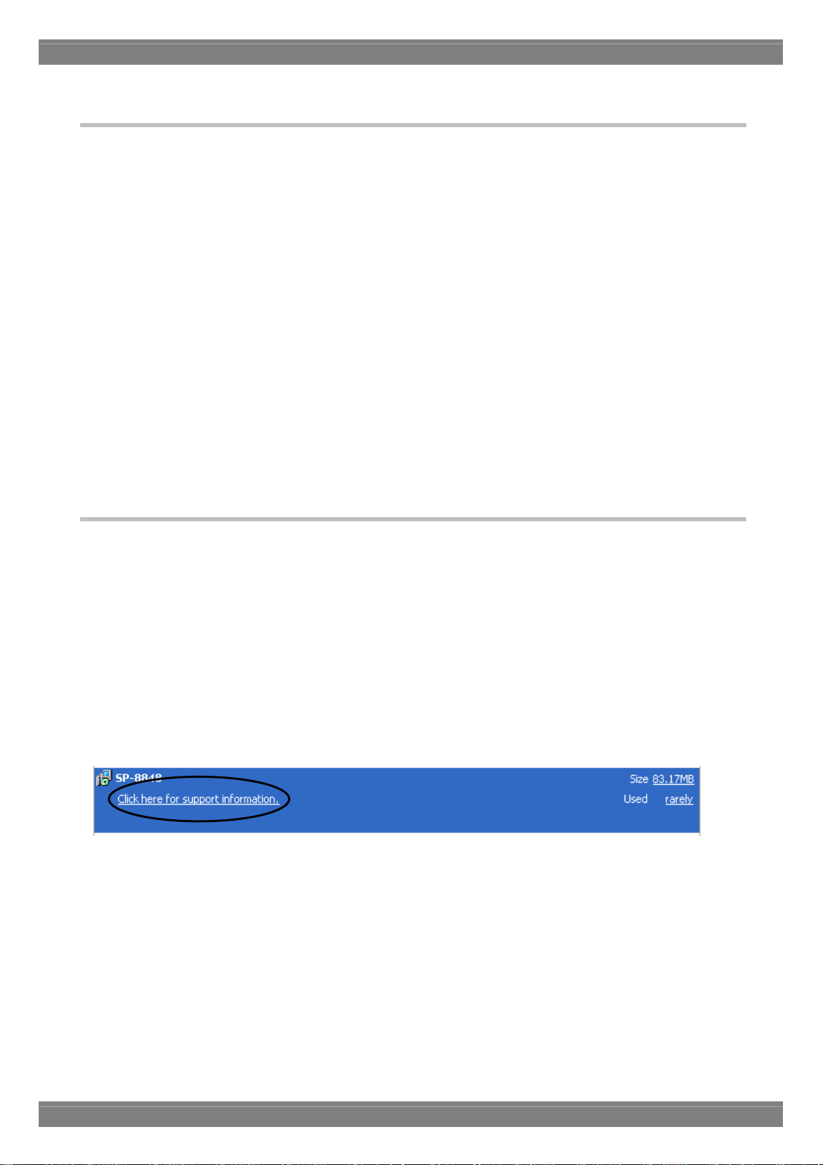
(3) Select SP-8848 in the [START] – [SET] – [Control Panel] – [Add and delete Application] .
Then, click the below figure.
6
Page 15
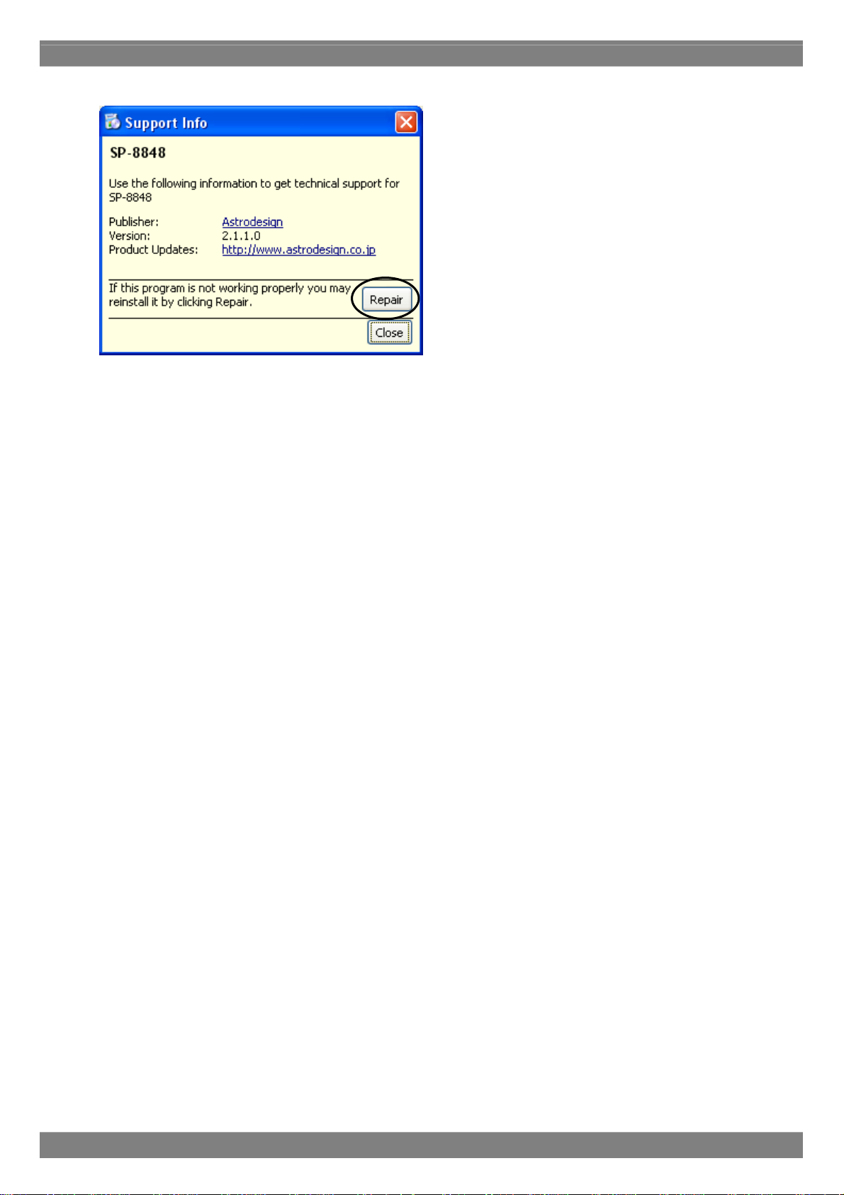
The below screen is shown.
(4) By pressing “Repair” button, SP-8848 is re-installed.
(5) When repair work is done, SP-8848 can be used.
Chapter 1 About the SP-8848
7
Page 16

8
Page 17
Operation
2
2
2.1. General
The basic operations consist of starting up "VGBase," creating and editing data, sending the data to and receiving it
from the VG, and storing the created data in the memory. The layout data used by "VGBase" is grouped together in sets,
and the data, data numbers, codes, etc. sent to the VG are retained in the memory. (For details on how to create and
edit the sets of data, refer to the help sections in the editing programs concerned.)
*Each setting screen is a thing at the time of VG-848 connection. Setting
screens may differ at the time of connection with other VG(s).
2.2. Starting up VGBase
Procedure for starting up "VGBase"
(1) Select [Start] → [Programs] → [SP-8848] → [VGBase].
*When connecting with VG-848, 849, 835, 859 and 830, SP reads the version number of
VG when SP starts. If the version is before 2.00, the message appears.
When message appears, upgrade the firmware of VG first.
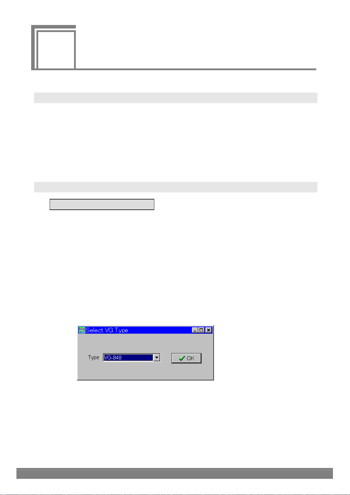
(2) The "Select VG Type" dialog box for setting the VG type now appears. Select the VG Type from the options given in
the [Type] combo box, and click the [OK] button. (Once the VG Type is selected, the selection is stored in the memory,
and the dialog box will no longer be displayed when the software program is next started up.) Before the "Select VG
Type" dialog box appears, a "Warning" message (Com Port Open Error) may be displayed. This means that
communication with the VG has not been established: after starting up "VGBase," perform the configuration settings.
(See "Configuration settings" in Section 3-3.)
9
Page 18
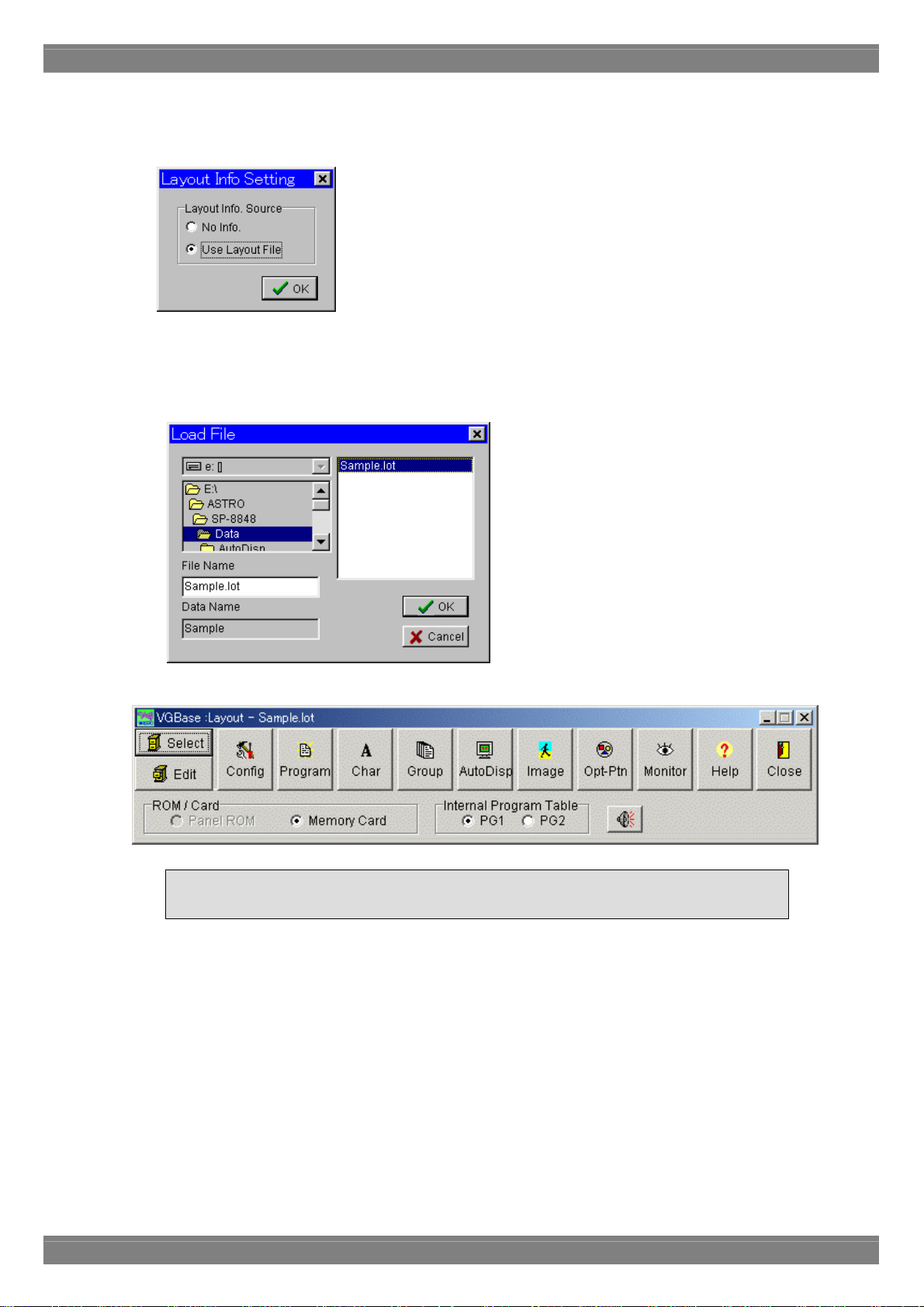
(3) The "Layout Info Setting" (layout data setting) dialog box for setting the data at startup appears. If layout data is to be
used, select [Use Layout File], and click the [OK] button. Otherwise, select [No Info], and click the [OK] button. If the
no data layout will be used, "VGBase" is started up here.
(4) When the layout data is going to be used, the "Load File" file selection dialog box appears. (It does not appear when
the layout data is not going to be used.) Select the "Sample.lot" file in the Data directory (default:
"C:¥Astro¥SP-8848¥Data"), and click the [OK] button. (When a new file is to be created, enter its filename in the [File
Name] box.)
(5) The sample layout data is now loaded into "VGBase" and "VGBase" is started up.
In order to perform the interface and other settings, the configuration settings must be
performed once when the VG is started up. (See "Configuration settings" in Section 3-3.)
10
Page 19
Chapter 2 Operation
2.3. Closing VGBase
Procedure for closing "VGBase"
Click the [Close] button.
2.4. Configuration settings
Procedure for changing the VG execution mode and other configuration settings
2.4.1. Startup method
Click the [Config] button of "VGBase." This starts up the "Configuration Editor" program which performs the
configuration settings.
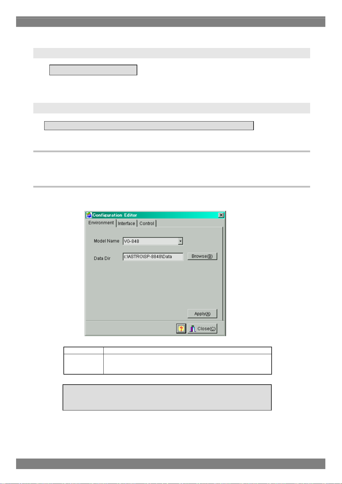
2.4.2. Window screen and description
■ Environment page
The directory containing the data files can be set on this page.
Model Name The VG model name is indicated here.
Data Dir The directory in which the data is stored is set here. Under normal
All the settings must match the communication parameters which are set for the
VG unit. As such, special care is required when setting or changing the items on
circumstances, no changes should be made to the directory since it
requires a specific structure.
11
Page 20
b
Click [Apply] so that the configuration settings will take effect and the actual changes will be made. When this button is
clicked on the [Interface] page, the commands are sent to the VG unit and the settings are changed only if
communication is enabled. If communication is disabled, only the configuration data managed by the PC will be
updated.
Click [Close] to close the configuration setting program.
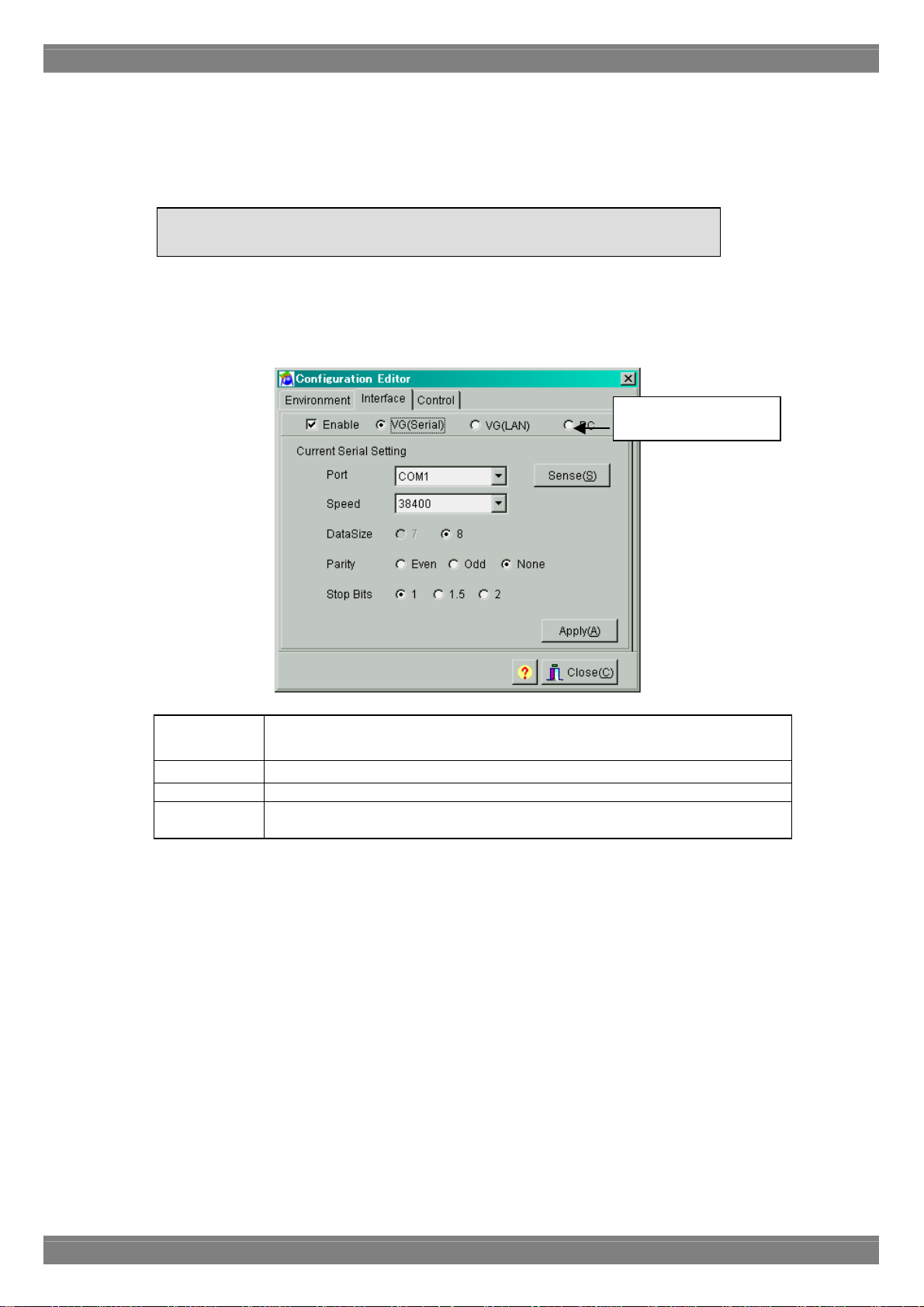
■ Interface page
The parameters for communication with the VG unit can be set on this page.
Bear in mind that even when the settings have been changed, these changes will
e lost if the software is closed without clicking the [Apply] button first.
Select the communication
method here.
Selecting the communication method
Enable This setting enables communication and allows "VG (Serial)," "VG (LAN)" or
"PC" to be set. The setting items differ depending on the VG model.
VG (Serial) This setting selects the RS-232C port to be used as the communication method.
VG (LAN) This setting selects the LAN to be used as the communication method.
PC This setting selects access to the memory card, which is connected directly to the
PC and on which is written the data, as the communication method.
12
Page 21
Chapter 2 Operation
When VG (Serial) has been selected as the communication method:
Port The port number is selected here.
[Sense] button This is used to detect the setting speed of the VG automatically.
Speed 9600, 19200, 38400, 57600 or 115200 is selected as the transfer rate
setting here.
Data Size This setting selects the communication data size (fixed at 8 bits).
Parity Even, Odd or None is selected as the parity setting here.
Stop Bits 1, 1.5 or 2 bits are selected as the Stop Bits setting here.
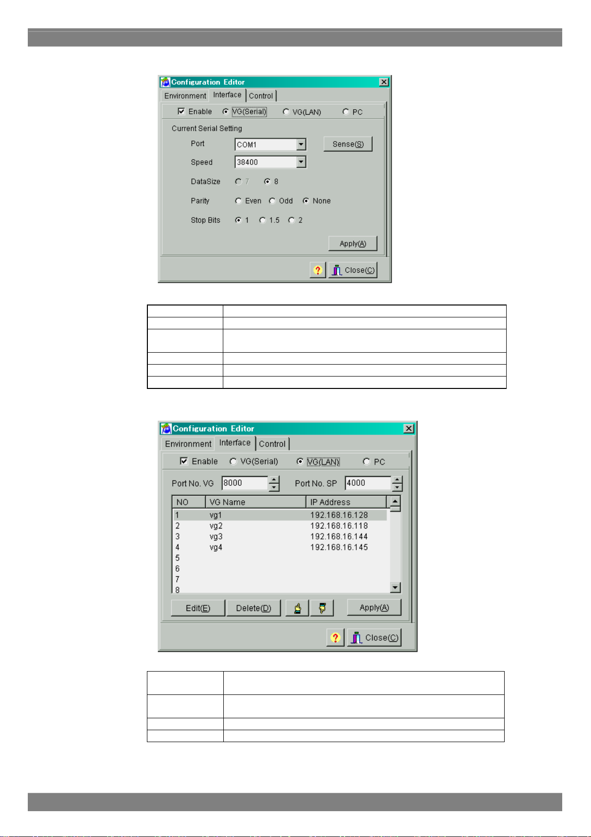
When VG (LAN) has been selected as the communication method:
Port No. VG The VG port number is selected here. The default setting is 8000.
(*1)
Port No. SP The SP port number is selected here. The default setting is 4000.
(*1)
[Edit] button This is used to display the IP address setting dialog box.
[Delete] button This is used to delete the VG selected on the list.
13
Page 22
*1: As a general rule, use the default value for the port number. If it cannot be used due to the network
connected, change to a different port number for use.
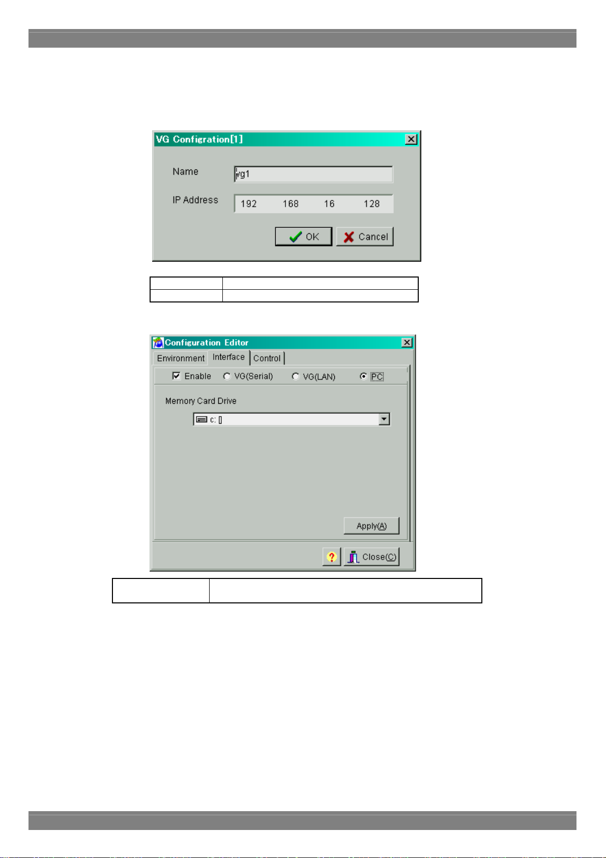
When the [Edit] button is pressed, a setting dialog box such as the one shown below appears.
Name The VG name is displayed here.
IP Address The IP address is displayed here.
When PC has been selected as the communication method:
Memory Card Drive The drive to which the memory card (*) is connected is selected
here when PC has been selected as the communication method.
*Use the Compact Flash (CF) card provided with the VG-848 as a standard accessory for the memory card.
14
Page 23
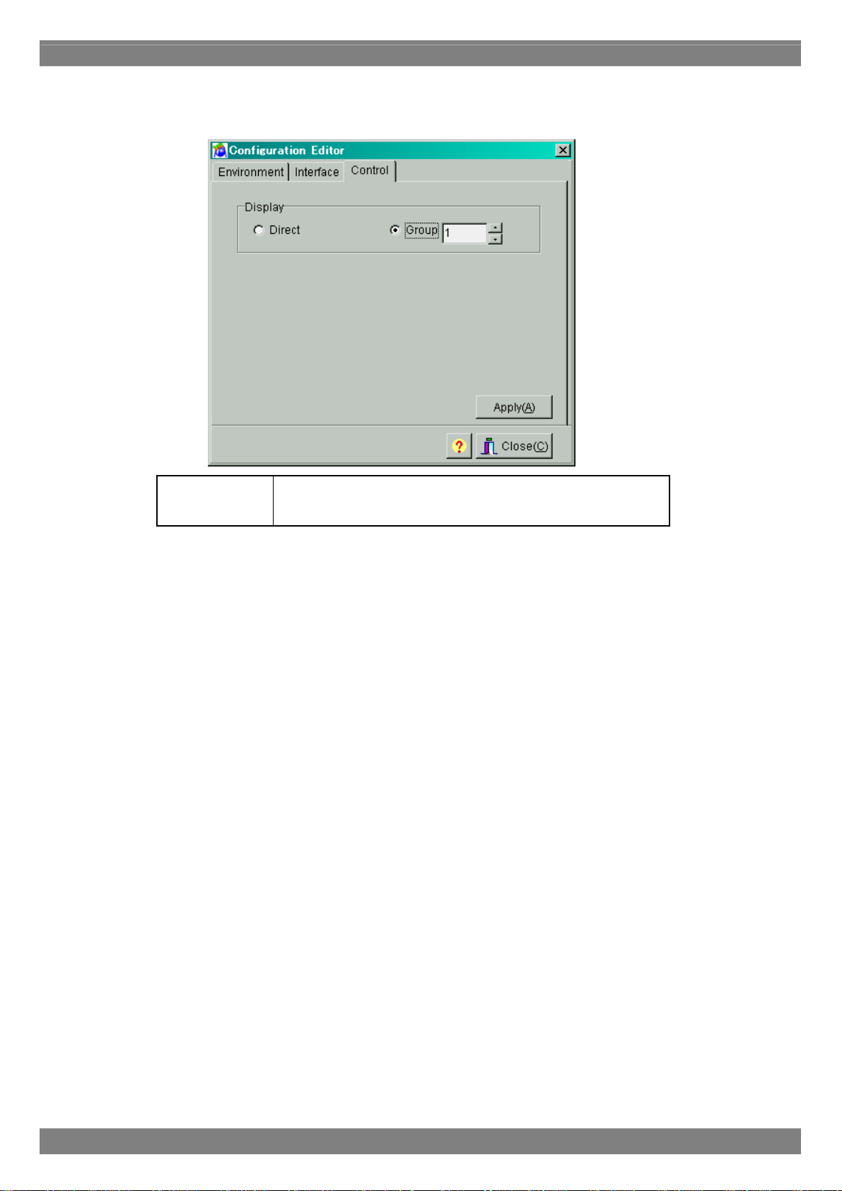
■ Control page
The display mode settings of the VG can be changed on this page.
Display
Chapter 2 Operation
"Direct Display" or "Group Display" can be selected here as the
display mode. When the "Group Display" mode has been selected,
the "Group" number must be specified.
15
Page 24
2.5. Creating and editing the program data
2.5.1. Startup method
Click the [Program] button of "VGBase" to start up the "Program Editor." When the editor starts up, the timing data
setting screen appears as the default display.
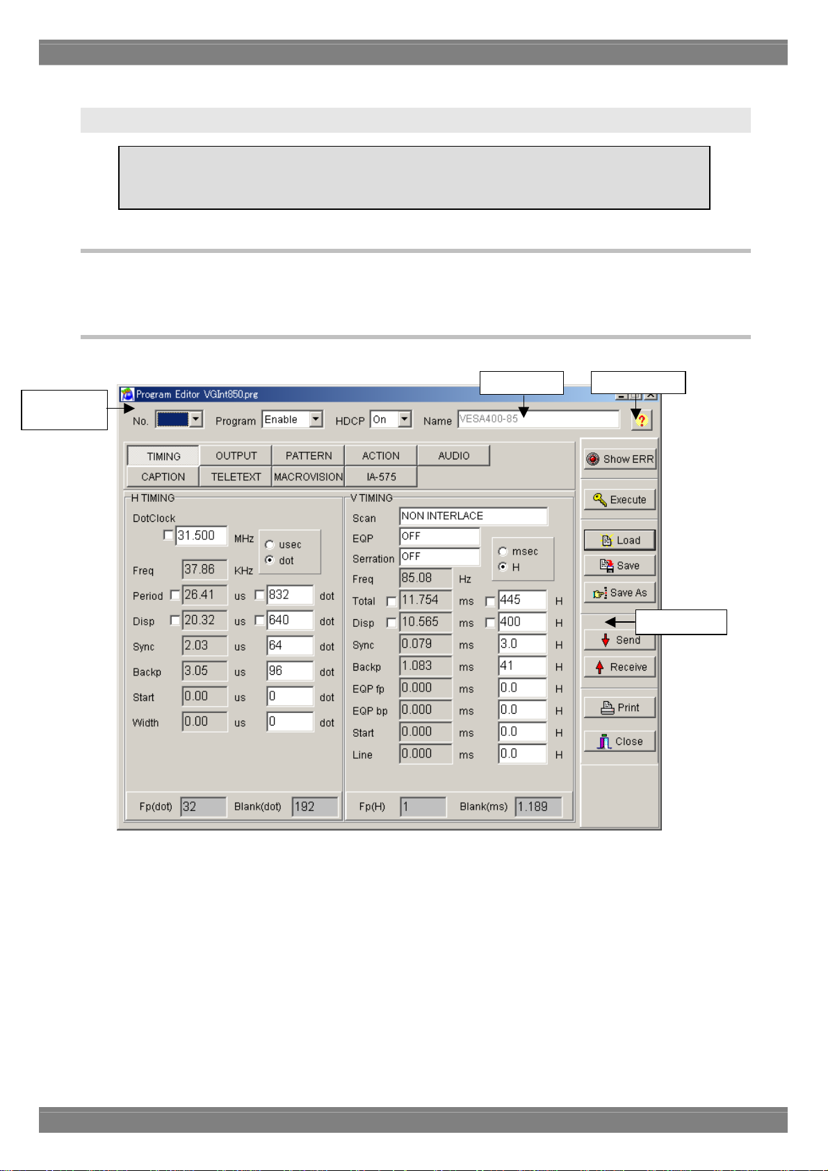
2.5.2. Window screens and description
■ Common setting screen
Program data
number
This section describes how the VG program data is set. Program data can be created, edited,
sent to the VG, registered on the panel ROM or memory card, executed and received from the
VG.
Filename
Help display
Program number
The number of the program data registered in the VG is displayed here.
Enable
Whether the program is to be sent to the VG and executed is set here.
Filename
The name of the file currently opened is displayed here.
Tool buttons
16
Page 25
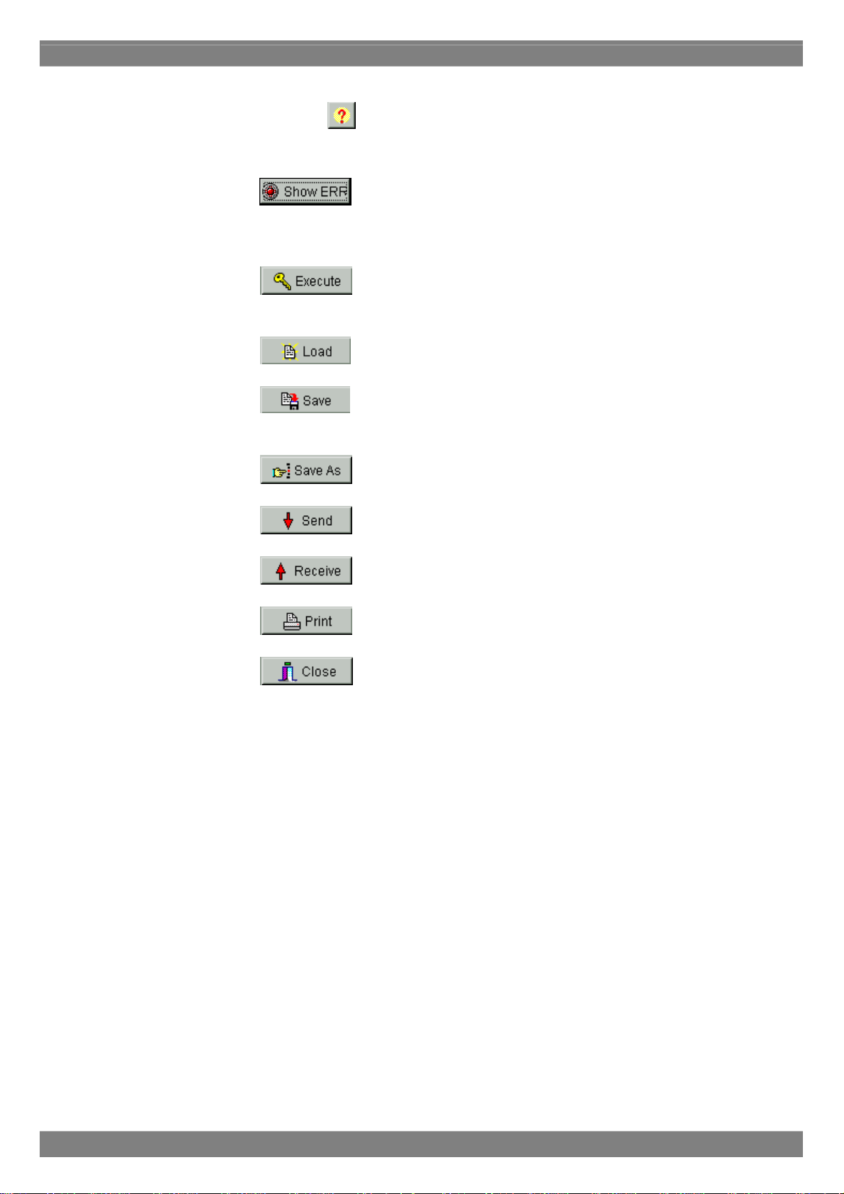
Help
Chapter 2 Operation
Help details are displayed by pressing the
Tool buttons
Show Err: When the
data which has been set. If a value outside the setting range has been input, which data contains
the error is indicated on the error description display screen.
Execute: When the
without its being registered in the VG.
Load: When the
Save: When the
existing data in that file is overwritten.
Save As: When the
Send: When the
button.
button is clicked, the error window is displayed. Check the values of the
button is clicked, the program data now being edited is executed
button is clicked, the program data is loaded.
[Save] button is clicked, the program data is saved in the file and any
button is clicked, the program data is saved in the file.
button is clicked, the program data now being edited is sent to the VG.
Receive: When the
Print: When the
Close: When the button is clicked, the program whose data has been edited is closed.
button is clicked, the program data is received from the VG.
button is clicked, the program data is printed.
17
Page 26
Basic operations
①Loading a file
Before creating new data, proceed with "Creating and editing the program data" in (2) on the next page.
1) Press the [Load] button to open the "Load File" file selection dialog box.
2) Select the filename.
3) Select the type of the program data ([Timing], [Output], [Pattern] or [Action]) to be loaded, and press the [OK]
button. Only the selected data is now loaded. The data which has not been selected is not updated.
4) The data of the selected file is displayed in the program data editing program.
If the layout has been set
The number of the program data registered in the layout is displayed at [No.].
If the layout has not been set
[No.] is cleared.
(*)When [Internal Program] has been checked
Load the file containing the program data registered in the ROM inside the VG. However, NTSC, PAL, SECAM,
1080i, 1080p, 1035i and 720p signals are standard signals and, as such, they cannot be edited using this software.
Filename Program data No.
VGInt850.prg 850
: :
VGInt999.prg 999
When, while loading the data of an old mo del, the data of setting items featured with the VG-848
but not with the old model has been lo aded into the SP-8848, default values (0 or the minimum
value) will be entered into those items. For details, refer to the SP-8848 help or the instruction
manual of the VG concerned.
②Creating and editing the program data
To set the timing data (horizontal timing, vertical timing):
→ Click the [TIMING] button.
To set the output conditions (analog output, digital output):
→ Click τηε [OUTPUT] or [ANALOG OUTPUT] or [DIGITAL OUTPUT] button.
To set the pattern data (selecting the display pattern, setting the pattern data):
→ Click τηε [PATTERN] button.
To set the action data:
→ Click the [ACTION] button.
To set the audio data:
→ Click the [AUDIO] button.
(*) A setting with an error is displayed in red. A list of setting errors can be viewed by pressing [Show ERR].
With some VG models, changes have been made to the screens, setting items, setting value ranges, etc.
For details, refer to the SP-8848 help or the instruction manual of the VG concerned.
18
Page 27
Chapter 2 Operation
③Saving the file
After changing the program data, click the [Save] button or [Save As] button to save the data in the file.
When the [Save] button is clicked:
The data is saved in the file and any existing data in that file is overwritten.
When the [Save As] button is clicked:
1) The "Save File" file selection dialog box appears.
2) Input the filename, and select the [OK] button. The displayed data is now saved in the new file.
④Sending the program data
1) Select the [Send] button. The "Send to VG" number selection dialog box appears.
2) Set the number (0 to 849) of the program data.
Data number
0 After the data is sent, it is executed immediately
without being registered.
1 849
3) Click the [OK] button. The data is now sent to the VG. (The number of the data sent now replaces the previous
number appearing in [No.].)
(*) The name of the program data can be set by inputting it into [Program Name] of the [NAME] program data name
setting tab on the pattern data setting screen.
⑤Receiving the program data
1) Select the [Receive] button. The "Receive from VG" number selection dialog box appears.
2) Set the number (1 to 999) of the program data.
3) Select the data (Timing, Output, Pattern or Action) to be received, and click the [OK] button. Only the data selected
is loaded. Unselected data is not updated.
4) The data is received from the VG. (The number of the data received now replaces the previous number appearing
in [No.].)
⑥Printing the program data
1) Click the [Print] button to print the data prepared.
2) The "Print" dialog box appears. Set the margins here.
3) Click the [OK] button. The displayed data is now printed.
4) To change the printer which has been set, click the [Set Printer...] button.
5) The printer setting dialog box appears. Perform the printer settings. For details on how the items on this dialog box
are set, refer to the instruction manual for Windows or for the printer which will be used.
Program data can be received using an old VG model but except VG-828 it cannot be sent to one.
[with Execute] checked After the data is sent, it is registered and executed
immediately.
[with Execute] unchecked After the data is sent, it is not executed but only
registered.
19
Page 28
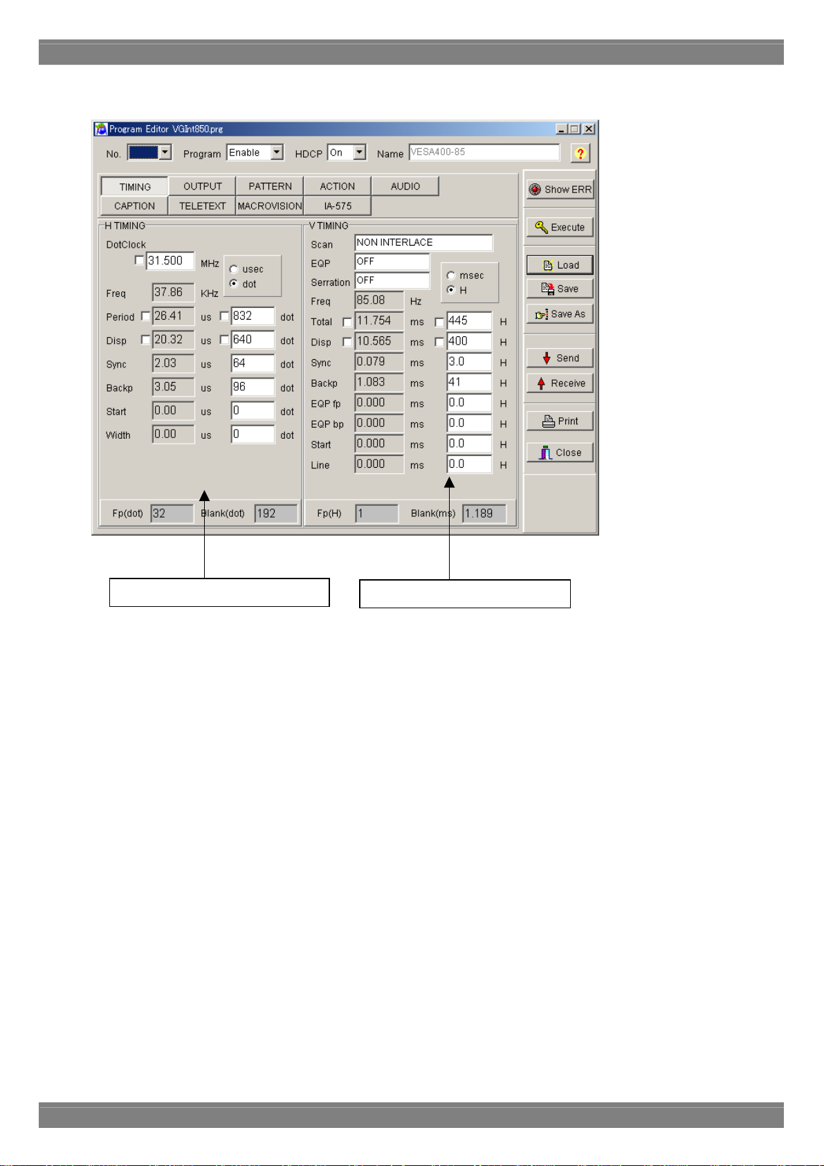
■ Timing data setting screen
[Setting the data]
● Align the mouse cursor with the data to be changed, and click the mouse. The data can now be keyed in.
[Setting the input mode]
● Select microseconds (usec), dots or kHz as the units for the horizontal timing (H TIMING) data and milliseconds
[Setting the fixed mode]
● A fixed mode is provided for DotClock, Period and Disp of the horizontal timing (H T IMING) data and Total and Disp
Horizontal timing data setting
(msec), H or Hz as the units for the vertical timing (V TIMING) data. The check box enabling th e unit to be input
changes.
of the vertical timing (V TIMING) data so that these data items will not be changed when other data items (such as
DotClock and Period) have been changed. Check the fixed mode if changes are not going to be made to these data
items.
Vertical timing data setting screen
20
Page 29
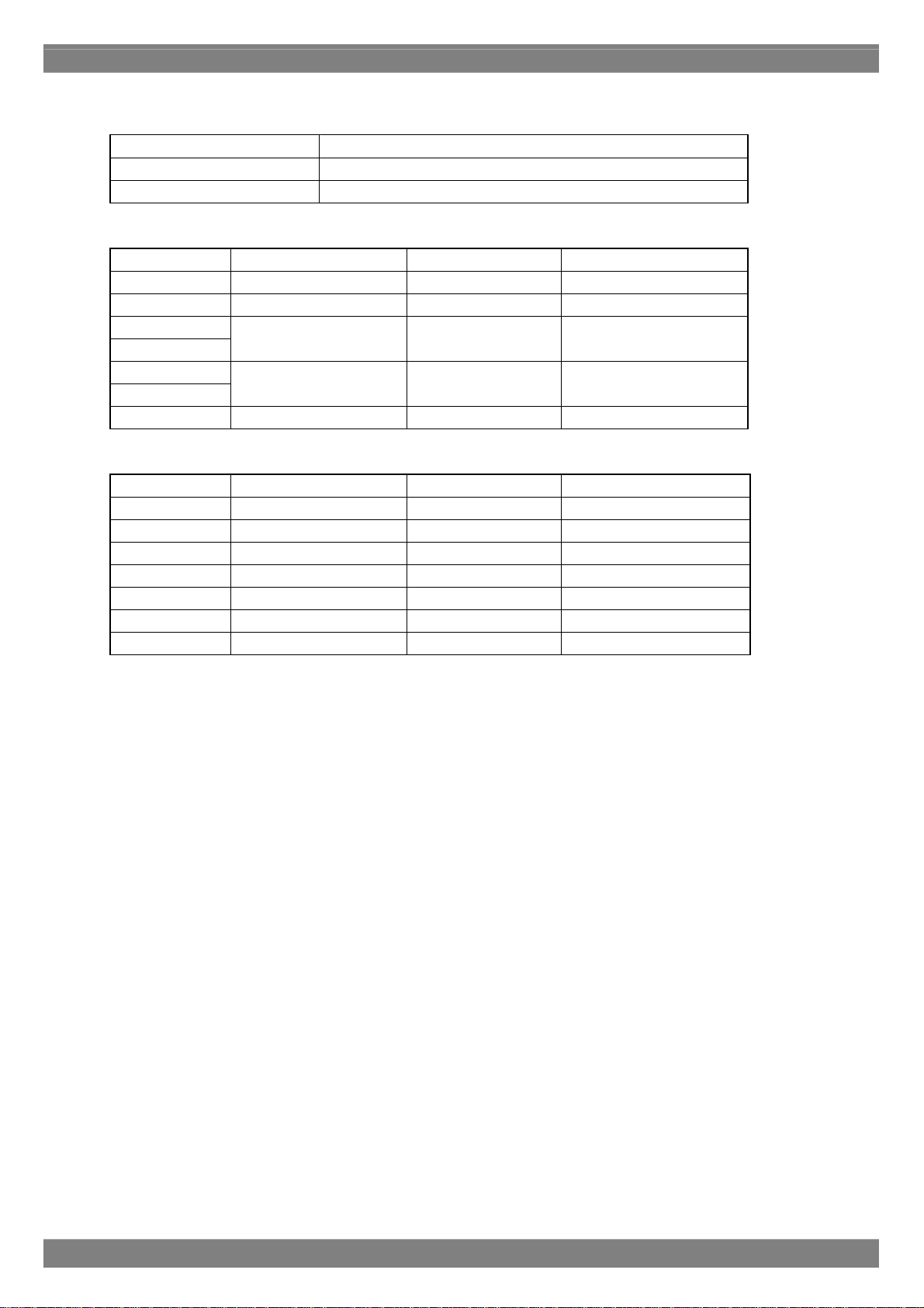
Timing data settings
[Frequencies]
Dot clock frequency 5.000 to 300.000 MHz
Horizontal sync frequency 10.000 to 300.000 kHz
Vertical sync frequency 15.600 to 200.000 Hz
[Horizontal timing data]
H Period
H Disp
H Sync
H Backp
H Frontp
HD start
HD width
0.000 to 99.999µsec
0.000 to 99.999µsec
0.000 to 99.999µsec
0.000 to 99.999µsec
0.000 to 99.999µsec
128 to 8192 dot 1-dot increments
48 to 4096 dot 1-dot increments
0 to 4096 dot 1-dot increments
0 to 4096 dot 1-dot increments
0 to 4096 dot 1-dot increments
H Blanking Calculated automatically 1-dot increments
[Vertical timing data]
V Total 0.000 to 99.999msec 4.0 to 8192 H 1H increments
V Disp 0.000 to 99.999msec 1.0 to 4093 H 1H increments
V Backp 0.000 to 99.999msec 0.0 to 4000 H 1H increments
V Sync 0.000 to 99.999msec 1.0 to 99 H 1H increments
EQP fp 0.000 to 99.999msec 0.0 to 99 H 1H increments
EQP bp 0.000 to 99.999msec 0.0 to 99 H 1H increments
Start 0.000 to 99.999msec 0.0 to 4095 H 1H increments
Line 0.000 to 99.999msec 0.0 to 4095 H 1H increments
Chapter 2 Operation
21
Page 30
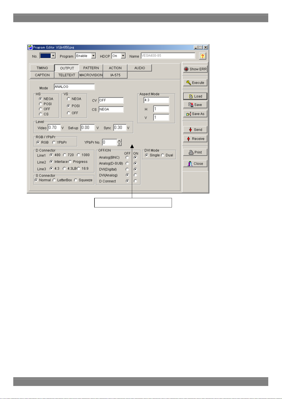
■ Output condition data setting screen
Output condition data setting screen
[Setting the data]
● Select the applicable radio buttons.
● Where an edit box is provided, align the mouse cursor with the data to be change d, and click the mouse. The dat a
can now be keyed in.
22
Page 31

Output condition data settings
Mode ANALOG, Tri-Sync (1080) ,Tri-Sync (720) ,NTSC ,PAL ,SECAM is selected here.
HS "NEGA," "POSI" or "OFF" is selected here as the HS polarity setting.
VS "NEGA," "POSI" or "OFF" is selected here as the VS polarity setting.
CV "OFF," "R," "G," "RG," "B," "RB," "GB" or "RGB" is selected here as the CV setting.
CS "NEGA," "POSI" or "OFF" is selected here as the CS polarity setting.
VIDEO LEVEL A voltage level from 0.3 to 1.0V is set here as the video level.
SET UP A voltage level from 0 to 0.25V is set here as the setup level.
SYNC LEVEL A voltage level from 0 to 0.06V is set here as the sync level.
PbPr No. A number from 0 to 9 is set here as the color difference table number.
RGB/Y,B-Y,R-Y Either "RGB" or "Y,B-Y,R-Y" is set here as the color difference setting.
DVI Mode Either "Single" or "Dual" is selected here as the DVI output setting.
D Conector(Line1) "480," "720" or "1080" is selected here as the Line1 setting.
D Conector(Line2) "Interlace" or "Progress(ive)" is selected here as the Line2 setting.
D Conector(Line3) "4:3," "4:3LB" or "16:9" is selected here as the Line3 setting.
S Conector "Normal," "Letter Box" or "Squeeze" is selected here as the S Connector output.
Analog(BNC) "ON" or "OFF" is selected here as the Analog (BNC) setting.
Analog(D-SUB) "ON" or "OFF" is selected here as the Analog (D-SUB) setting.
DVI(Digital) "ON" or "OFF" is selected here as the DVI (Digital) setting.
DVI(Analog) "ON" or "OFF" is selected here as the DVI (Analog) setting.
D Conect "ON" or "OFF" is selected here as the D Connect setting.
Chapter 2 Operation
23
Page 32

n
■ Pattern data setting screen
Buttons for selecting
the patterns
Character patter
settings
Buttons for setting the
respective patterns
Selecting the patterns
Select the pattern to be displayed while the VG is running.
Select "Multi Pattern" or "Single Pattern" as the Mode setting. ("Multi Pattern" is the default.) NAME, R, G, B and INV
can be set at the same time for any of the patterns.
● When "Multi Pattern" is selected : The OPT1 and OPT2 patterns cannot be set at the same time. A multiple number
of the other patterns can be set at the same time.
● When "Single Pattern" is selected : A multiple number of patterns cannot be set at the same time.
24
Page 33

Pattern selection
CHARA Character
CROSS Crosshatch
DOTS Dots
CIRCLE
CURSOR
NAME Program data name
COLOR Color bar
GRAY Gray scale
BURST Burst
WINDOW Window
OPTI1
OPT2 Optional pattern 2
R Red output
G Green output
B Blue output
INV Inversion
Pattern settings
CHARA: Character pattern
This button is used to set the character pattern.
Chapter 2 Operation
Circle
Center marker
Edge marker
Diagonal line
Cursor
Optional pattern 1
Code The character code is set here.
Format The format of the character pattern which has been set is selected here.
Font The font size is selected here.
Cell size The horizontal cell size (H) and vertical cell size (V) are selected here.
25
Page 34

CROSS: Crosshatch pattern
This button is used to set the crosshatch pattern.
The crosshatch pattern is always displayed after the screen center has been calculated. The screen center can be
calculated when the number of display dots and number of display lines are odd numbers. However, when they are
even numbers, the actual screen center will be one dot to the right and one line below the center. An error results when
0 is set for both H and V.
Mode Specification as a number of lines (line) or dot intervals (dot) is selected here as
the mode setting.
Format The save start point (From Center or From Top Left) is selected here.
Interval The number of lines (when "line" has been selected) or the dot interval (when
"dot" has been selected) of the crosshatch pattern is set here.
Width The width of the drawn lines is set here.
26
Page 35

Chapter 2 Operation
DOTS: Dot pattern
This button is used to set the dot pattern.
The dot pattern is always displayed after the screen center has been calculated. The screen center can be calculated
when the number of display dots and number of display lines are odd numbers. However, when they are even numbers,
the actual screen center will be one dot to the right and one line below the center. An error results when 0 is set for both
H and V.
Mode Specification as a number of lines (line) or dot intervals (dot) is selected here
as the mode setting.
Format The save start point (From Center or From Top Left) is selected here.
Interval The number of lines (when "line" has been selected) or the dot interval (when
"dot" has been selected) of the dot pattern is set here.
Dot size The dot size is set here.
Dot type The type of dots is set here.
27
Page 36

CIRCLE: Circle pattern
This button is used to set the circle pattern.
The number of circles, etc. can be set.
Format This is selected on the basis of the data which has been set.
Aspect The aspect ratio of the monitor is set here. The ratio is considered
to be 1:1 when 0 is used for H or V setting.
28
Page 37

CURSOR: Cursor pattern
This button is used to set the cursor pattern.
Chapter 2 Operation
Format The shape of the cursor is selected here.
Flicker The flicker setting is selected here.
Position (PosDisp) The method of displaying the cursor position is selected here.
Step The cursor movement step is selected here.
Color The RGB values of the cursor are selected here.
Background Color The RGB values of the background color are selected here.
29
Page 38

COLOR: Color bar pattern
This button is used to set the color bar pattern.
The color bar pattern is always drawn in accordance with the interval provided and from the top left corner toward the
screen center. This interval setting is used for both color bar and gray scale.
Mode The interval setting increment (specified as a percentage or dot number) is
selected here.
Interval The horizontal (H) width and vertical (V) width are selected here.
Direction The layout direction is selected here.
Chapter 5 Repeat
The color values from 0 to repeat are set here when level values are to be used
repeatedly.
Color The RGB values are set here.
30
Page 39

Chapter 2 Operation
GRAY: Gray scale pattern
This button is used to set the gray scale pattern.
When the analog mode or Tri-Sync has been selected as the output condition "Mode" setting, "Level" can be set; when
the TTL mode has been selected, "Color" can be set.
The gray scale pattern is always drawn in accordance with the interval provided and from the top left corner toward the
screen center.
Mode The interval setting increment is selected here.
Direction The layout direction is selected here.
Repeat The color values from 0 to repeat are set here when level values are to be used
repeatedly.
Interval The interval between the shades of gray is set here.
When the analog mode or Tri-Sync has been selected as the output condition "Mode" setting:
Level : The gray display levels are set here.
When the TTL mode has been selected as the output condition "Mode" setting:
Color : The halftone levels are set here.
* 8bit or 10bit can be selected in VG-835. The level can be set between 0 to 255 in 8 bit mode, 0 to 1023 in 10
bit mode.
* 8bit , 10bit and 12bit can be selected in VG-835-A. Th e level can be set between 0 to 255 in 8 bit mode, 0 to
1023 in 10 bit mode, 0 to 4095 in 12 bit mode.
31
Page 40

BURST: Burst pattern
This button is used to set the burst pattern.
Format The drawing start point is selected here.
Step The increment for the thickness of the vertical lines is selected here.
Interval The number of vertical lines of the same thickness which are to be displayed
is selected here.
32
Page 41

Chapter 2 Operation
WINDOW: Window pattern
This button is used to select the window pattern.
When the analog mode or Tri-Sync has been selected as the output condition "Mode" setting, "Analog Color" can be
set; when the TTL mode has been selected, "TTL Color" can be set.
Mode The size setting increment (specified as a percentage or dot number) is selected
here.
Size The horizontal size (H) and vertical size (V) are selected here.
Format The window already set is selected here.
Flicker The scroll speed is selected here.
* The "Flicker Level" button becomes effective if it is set in 4Level and
16Level. Then, each set screen is d isplayed.
Flicker Level
button
When the analog mode or Tri-Sync has been selected as the output condition "Mode" setting:
Analog RGB : The window colors are set here.
When the TTL mode has been selected as the output condition "Mode" setting:
TTL Color : The Video and halftone values are set here.
* 8bit or 10bit can be selected in VG-835 and VG-857. The level can be set between 0 to 255 in 8 bit mode, 0 to
1023 in 10 bit mode.
* 8bit , 10bit and 12bit can be selected in VG-835-A , VG-849C and VG-859C. The level can be set between 0 to
255 in 8 bit mode, 0 to 1023 in 10 bit mode, 0 to 4095 in 12 bit mode.
Setting screen of Window 4Level Flicker and Window 16 Level Flicker is displayed.
33
Page 42

WINDOW: Window 4Level Flicker
Set the value of Window 4 Level Flicker. Window level can be set 4-level. Each level can output in the setting time (V
unit).
Time The flicker time is set. 0 to 255 v
Level The flicker level is set. 0 to 255
Close The Window 4Level Flicker setting screen is ended, and it returns to the Window
setting screen.
* 8bit or 10bit can be selected in VG-835. The level can be set between 0 to 255 in 8 bit mode, 0 to 1023 in 10
bit mode.
* 8bit , 10bit and 12bit can be selected in VG-835-A. Th e level can be set between 0 to 255 in 8 bit mode, 0 to
1023 in 10 bit mode, 0 to 4095 in 12 bit mode.
34
Page 43

Chapter 2 Operation
WINDOW: Window 16Level Flicker
Set the value of Window 16Level Flicker. Window level can be set 16-level. Each level can output in the setting time
(V unit).
Time The flicker time is set. 0 to 255 v
Level The flicker level is set. 0 to 255
Close The Window 16Level Flicker setting screen is ended, and it returns to the Window
setting screen.
* 8bit or 10bit can be selected in VG-835. The level can be set between 0 to 255 in 8 bit mode, 0 to 1023 in 10
bit mode.
* 8bit , 10bit and 12bit can be selected in VG-835-A. Th e level can be set between 0 to 255 in 8 bit mode, 0 to
1023 in 10 bit mode, 0 to 4095 in 12 bit mode.
35
Page 44

OPT: Optional pattern
This is used to set the optional patterns.
When an optional pattern is set, no other patterns can be superimposed onto it.
Option 1 (OPT1) The hexadecimal code of the optional pattern is set here.
Option 2 (OPT2) The hexadecimal code of the optional pattern is set here.
36
Page 45

Chapter 2 Operation
NAME: Program data name
This is used to display the name of the program data displayed.
A new program data name can be set by inputting the name into "Program Name" of the program data name setting tab
on the pattern data setting screen and saving it or sending it to the VG. The same procedure is adopted for changing a
name.
37
Page 46

GRAPHIC: Graphic color
This is used to set the graphic colors.
When the analog mode or Tri-Sync has been selected as the output condition "Mode" setting, "Analog Color" can be
set; when the TTL mode has been selected, "TTL Color" can be set.
When the analog mode or Tri-Sync has been selected as the output condition "Mode" setting:
Analog color : The RGB values are set here.
When the TTL mode has been selected as the output condition "Mode" setting:
TTL Color : The TTL color values are set here.
Background ON or OFF is selected here.
Background Color The RGB values of the background color are set here.
* 8bit or 10bit can be selected in VG-835. The level can be set between 0 to 255 in 8 bit mode, 0 to 1023 in 10
bit mode.
* 8bit , 10bit and 12bit can be selected in VG-835-A. Th e level can be set between 0 to 255 in 8 bit mode, 0 to
1023 in 10 bit mode, 0 to 4095 in 12 bit mode.
38
Page 47

■ Action data setting screen
Chapter 2 Operation
Pull-down scroll
Action data setting screen
Action data setting screen
Click the check box to the left of the action data type to be set to check it. The setting items for each type can now be
selected.
Pull-down scroll
Scrolling can be simulated by employing the 2-3 pull-down function and other scroll functions.
2-3 pull down function
This is a conversion method for ensuring the coordination of 30 fps/60-field NTSC signals with 24 fps films when
converting regular movies and other film sources into video signals. The first frame of the film is converted into the
equivalent of 2 fields and the second frame into the equivalent of 3 fields, and the resulting 5-field format for every 2 film
frames is repeated so that 24 frames are converted into 60 fields. DVD players which support a progressive output
capability can detect this 2-3 pull-down processing information and reproduce the 24 original frames. However, a TV
monitor which supports the progressive system must be used for playback.
39
Page 48

Pattern pull-down scroll setting screen
Interval2 The interval from 0 to 999V is set here.
Interval3 The interval from 0 to 999V is set here.
Interval4 The interval from 0 to 999V is set here.
Pattern
H‐Step2
H‐Step3
H‐Step4
V‐Step2
V‐Step3
V‐Step4
The number of steps from 0 to 4095 dots is set here.
The number of steps from 0 to 4095 dots is set here.
The number of steps from 0 to 4095 dots is set here.
The number of steps from 0 to 4095 dots is set here.
The number of steps from 0 to 4095 dots is set here.
The number of steps from 0 to 4095 dots is set here.
Window
Step2 The number of steps from 0 to 255 dots is set here.
Step3 The number of steps from 0 to 255 dots is set here.
Step4 The number of steps from 0 to 255 dots is set here.
40
Page 49

Setting ranges
Action interval Action Interval 1 to 999 V
Interval2 0 to 999 V
Interval3 0 to 999 V
Interval4 0 to 999 V
Character flicker
Window flicker ON/OFF
Pattern scroll
Window scroll
Palette scroll PalNo.1 0 to 255
PalNo.2 0 to 255
Step -128 to 127
ON/OFF
Character Scroll
Graphic Scroll Left, Right, Up, Down, LeftUp,
HRepeat 1 to 15
VRepeat 1 to 15
HStep 1 to 4096 dots
VStep 1 to 4096 dots
HStep2 0 to 4096 dot
VStep2 0 to 4096 dot
HStep3 0 to 4096 dot
VStep3 0 to 4096 dot
HStep4 0 to 4096 dot
VStep4 0 to 4096 dot
Left, Right, Up, Down, LeftUp,
Step 1 to 255 dot
Step2 0 to 255 dot
Step3 0 to 255 dot
Step4 0 to 255 dot
Left, Right, Up, Down, LeftUp,
RightUp, RightDown, Moving
RightUp, RightDown, Moving
RightUp, RightDown, Moving
Chapter 2 Operation
41
Page 50

■ Audio data setting screen
Sweep Mode settings
Frequency settings
Level settings
Sweep Mode
"Sweep OFF," "Frequency," "LEVEL(L)" or "LEVEL(R)" is selected as the Sweep Mode setting.
Frequency
The frequency is set in the LEFT and RIGHT fields.
Any frequency from 100 to 20,000 Hz can be set in each field.
The settings are performed in 100 Hz increments.
Level
The level is set in the LEFT and RIGHT fields.
Any level from 0 to 2000 mV can be set in each field.
The settings are performed in 50 mV increments.
42
Page 51

⑥
⑨
■ HDMI data setting screen
※AsettingscreenisathingatthetimeofVG-849selection.
①
②
④
⑦
Chapter 2 Operation
③
⑤
⑧
43
Page 52

No. Item name Details
① HDMIMode
Video ・VideoFomat
②
Audio ・AudioSource
③
④ YPbPrMatrix
⑤ SyncPolarity
⑥ Repetition
InfoFrame Setting
⑦
button
ACP Setting button
⑧
AFD Setting button
⑨
Set HDMI output mode. Select from OFF, HDMI, HDMI1.1, DVI, or AUTO.
Select the video format. Select from RGB, Y444, Y422_16, Y422_20, or
Y422_24.
・VideoLevel
Set the format of the video level. Select from Full range, Limited range, or USER.
If “USER” is selected, it is possible to input setting range by video format.
RGB, Y444, Y422_16 = 0 to 255
Y422_20 = 0 to 1023
Y422_24 = 0 to 4095
Select the output signal of the HDMI standard. Select from OFF, TOSLINK,
COAX, ANALOG or INTERNAL.
・AudioSampleFreq
Set the frequency. Select from 32kHz,44.1kHz,48kHz,88.2kHz,96kHz,176.4kHz,or
192kHz.
・AudioWidth
Set the audio bit width. Select from 16bit, 20bit or 24bit.
・AudioInternalSweep
Set the internal Sweep. Select from OFF or Freq.
・AudioInternalL-RLevel
Set the audio output level. The max value differs by the setting of AudioWidth
item.
16bit : 7FFF
20bit : 7FFFF
24bit : 7FFFFF
・AudioInternalL-RFreq
Set the output frequency. The max value differs by the setting of
AudioSampleFreq item.
32kHz:10kHz
44.1kHz:22.05kHz
48kHz:24kHz
Set the value of YPbPr. Input the appropriate number.
Display NEGA and POSI that is set in the part of “OUTPUT”.
Set the value of the Repetition. Set among 1 to 10.
InfoFramesettingscreenisdisplayed.
ACPsettingscreenisdisplayed.
AFDsettingscreenisdisplayed.
44
Page 53

■ InfoFrame data setting screen
※AsettingscreenisathingatthetimeofVG-849selection.
①
Chapter 2 Operation
②
③
④
45
Page 54

No.
①
②
③
Item name Details
AVI
SPD
Audio
ON/OFF
Select ON or OFF of InfoFrameAVI.
Type
Display the type of InfoFrameAVI.
Version
Set the version of InfoFrameAVI. Select either 1 or 2.
ScanInfo
Set the ScanInfo. Select from NoData, Overscanned, or Underscanned.
BarInfo
Set about the BarInfo. Select from NotValied, Vert, Horiz or Vert&Horiz.
Scaling
Set about the Scaling. Select from unknown, Vert, Horiz or Vert&Horiz.
ActiveFormatInfo
Set about the ActiveFormatInfo. Select either NoData or Valid.
RGB/YCbCr
Set either RGB or YcbCr. Select from RGB, YCbCr422 or YCbCr444.
ActiveAspectRatio
Set the active aspect ratio. Select from Same, 4:3, 16:9 or 14:9.
PictureAspectRatio
Set the picture aspect ratio. Select NoData, 4:3 or 16:9.
Colorimetry
Set about the Colorimetry. Select from NoData, SMPTE, or ITU709.
VideoCode
Set the VideoCode. Select between 0 and 34
Repetition
Set about the Repetition. Select between 1 and 10.
End of Top Bar
Set the Top Bar. Select between 1 and 65535.
Start of Bottom Bar
Set the Bottom Bar. Select between 1 and 65535.
End of Left Bar
Set the Left Bar. Select between 1 and 65535.
Start of Right Bar
Set the Right Bar. Select between 1 and 65535.
ON/OFF
Select ON or OFF of InfoFrameSPD.
Type
Display the type of InfoFrameSPD.
Version
Set the version of InfoFrameSPD. One version is fixed.
VendorName
Set the VendorName. Input using ASCII letters.
ProductDescript
Set the ProductDescript. Input using ASCII letters.
SourceDevice
Set the SourceDevice. Select from unknown, DigiSTB, DVD, DVHS, HDD, DVC,
DSC, CD, Game or PC.
ON/OFF
Select ON or OFF of InfoFrameAudio.
Type
Display the type of InfoFrameAudio.
Version
Set the version of InfoFrameAudio. One version is fixed.
Channel Count
Set the channel counting. Select from Refer, 2ch, 3ch, 4ch, 5ch, 6ch, 7ch or 8ch.
CodingType
Set the coding type. Select from Refer, IEC60958, AC3, MPEG1, MP3, MPEG2,
AAC, DTS or ATRAC.
SampleSize
Set the sampling size. Select from Refertostream, 16bit, 20bit or 24bit.
SampleFreq
Set the sampling frequency. Select from Refertostream, 32kHz, 44.1kHz, 48kHz,
88.2kHz, 96kHz, 176.4kHz or 192kHz.
Channel/Speaker Allocation
Set the speaker channel. Set between 0 and 31.
46
Page 55

④
Chapter 2 Operation
LevelShift
Set the level shift. Set between 0 and 15.
Down-mixInhibit
Select “Permitted” or “Prohibited” of using DownMix.
MPEG
ON/OFF
Select ON or OFF of InfoFrameMPEG.
Type
Display the Type of InfoFrameMPEG.
Version
Set the version of InfoFrameMPEG. One version is fixed.
BitRate
Set the BitRate within the range of 0 to 4294967295.
(4294M967K295Hz)
Frame
Set about the Frame. Select from unknown, I Picture, B Picture or P Picture.
FieldRepeat
Set about FieldRepeat. Select either New or Repeated.
47
Page 56

■ ACP data setting screen
※AsettingscreenisathingatthetimeofVG-849selection.
No.
①
①
Item name Details
ACP Packet
ON/OFF
Select ON or OFF of ACP.
ACP Type
ACP type setup. Please make a selection from Generic Audio, IEC60958, DVD
Audio, or Reserved for SACD.
DVD-Audio Type Dependent Generation
DVD-Audio Type Dependent Generation setup. Only one way to choose.
Copy Permission
Copy Permission setup. Please make a selection from 0, 1, 2, or 3.
* When ACP Type is set to DVD Audio, it can be selected.
Copy Number
Copy Number setup. Please make a selection from 0, 1, 2, 3, 4, 5, 6, or 7.
* When Copy Permission is set to 2, it can be selected.
Quality
Quality setup. Please make a selection from 0, 1, 2, or 3.
* When Copy Permission is set to two, it can be selected.
Transaction
Transaction setup. Please make a selection from 0 or 1.
* When Copy Permission is set to two, it can be selected.
Count_A
Count_A setup. Please make a selection from 0 to 255.
Count_S
Count_S setup. Please make a selection from 0 to 255.
Count_U
②
③
48
Page 57

②
③
Chapter 2 Operation
Count_U setup. Please make a selection from 0 to 255.
Q_A
Q_A setup. Please make a selection from 0 or 1.
Q_S
Q_S setup. Please make a selection from 0 or 1.
Q_U
Q_U setup. Please make a selection from 0 or 1.
Move_A
Move_A setup. Please make a selection from 0 or 1.
Move_S
Move_S setup. Please make a selection from 0 or 1.
Move_U
Move_U setup. Please make a selection from 0 or 1.
ISRC 1
ISRC 2 Select ON or OFF of ISRC2.
ON/OFF
Select ON or OFF of ISRC1.
ISRC Cont
ISRC Cont setup. Please make a selection from either 0 or 1.
ISRC Valid
ISRC Valid setup. Please make a selection from either 0 or 1.
ISRC Status
ISRC Status setup. Please make a selection from Starting, Intermediate, or Ending.
Validity Information
Validity Information setup. Please make a selection from No Validity, ISRC,
UPC/EAN, or UPC/EAN&ISRC.
Catalogue Code(UPC/EAN #1-#13)
Catalogue Code setup. Please setup using only 13 characters.
Country Code(ISRC #1-#2)
Country Code setup. Please setup using only 2 alphanumeric characters.
First owner Code(ISRC #3-#5)
First owner Code setup. Please setup using 3 alphanumeric characters.
Year of Recording Code(ISRC #6-#7)
Year of Recording Code setup. Please setup using 2 characters.
Recording (item) Code(ISRC #8-#12)
Recording (item) Code setup. Please setup using 5 characters.
49
Page 58

■ CEC data setting screen
※AsettingscreenisathingatthetimeofVG-849selection.
①
No.
①
②
③
④
Item name Details
CEC Mode setting
VG Logical Address
Transmission
command is set
Receiving command
is set.
Set CEC Mode.
Select among “Monitor”, “Sending” and “Respond”.
VG Logical Address
From which device the command is transmitted is set. Set the value from 0 to F.
* VG Logical Address and TX Initiator are adjusted each other. When either
value is changed, the other set value is changed.
TX Initiator
From which device the command is transmitted is set. Set the value from 0 to F.
* VG Logical Address and TX Initiator are adjusted each other. When either
value is changed, the other set value is changed.
TX Destination
To which device the command is transmitted is set. Set the value from 0 to F.
Op Code
Set Op Code of the command. Set the value from 00 to FF.
ParameterNum
Set the number of Parameter. Set the value from 0 to 14.
Parameter
Set the number of Parameter. Set the value from 00 to FF in each Parameter.
RX Initiator
From which device the command is transmitted is set. Set the value from 0 to F.
RX Destination
To which device the command is transmitted is set. Set the value from 0 to F.
Op Code
Set Op Code of the command. Set the value from 00 to FF.
ParameterNum
Set the number of Parameter. Set the value from 0 to 14.
Parameter
Set the number of Parameter. Set the value from 00 to FF in each Parameter.
② ③
④
50
Page 59

■ ADF data setting screen
※AsettingscreenisathingatthetimeofVG-849selection.
Chapter 2 Operation
The "EIA/CEA-861B standard" aspect ratio evaluation pattern can be set as optional pattern 1F. T he detailed settings
of optional pattern 1F are shown below.
Aspect Mode
For setting the actual aspect ratio.
AFD Aspect
For setting CodeFrame of the AFD which is defined by the EIA/CEA-861B standard.
AFD Type
For setting the number of the AFD which is defined by the EIA/CEA-861B standard.
AFD Color
For setting the color used for the circle of the optional pattern 1F.
AFD BG
For setting the color of the background used for the circle of the optional pattern 1F.
AFD Bar
For setting the color of the SideBar and LetterBox of the optional pattern 1F.
51
Page 60

■ ClosedCaption/V-chip data setting screen
ClosedCaption
V-chip
V-chip
V-chip data is set up. Please refer to a "2.18. ClosedCaption/V-chip data transmission tool" for details.
ClosedCaption
Caption data is set up. Please refer to a "2.18. ClosedCaption/V-chip data transmission tool" for details.
52
Page 61

■ Teletext data setting screen
Chapter 2 Operation
Execute
Page
Execute
Select ON or OFF for the output
Line
Set the teletext data transmission mode.
・4line : Four lines are set as the mode for transmitting the teletext data.
Display lines : Field1 = 20, 21. Filed2 = 333, 334
・8line : Eight lines are set as the mode for transmitting the teletext data.
Display lines : Field1 = 13, 14, 20, 21. Field2 = 326, 327, 333, 334
Line
53
Page 62

Page
This is used to set the pages for each of the channels. The contents of a page are as being shown below.
If a page with any other number is set, only the page number will be displayed.
Page Contents
100 Index Page
101 Test Page
102 Newsflash
103 Subtitle
200 Character Set(English)
201 Character Set (German)
202 Character Set (Swedish/Finnish/Hungarian)
203 Character Set (Italian)
204 Character Set (French)
205 Character Set (Portuguese/Spanish)
206 Character Set (Czech/Slovak)
301 Colours
302 White Flat
505 Clock Cracker
515 Multi Page
555 Test Pattern1
560 Test Pattern2
580 Test Pattern3
54
Page 63

■ Macrovision data setting screen
Macrovision Mode
Chapter 2 Operation
Mode
The output mode of a Macrovision is set up. The modes which can be set up for every setting timing differ.
55
Page 64

The mode which can be set up for every timing.
Timing Mode
NTSC-M
NTSC-J
PAL
PAL-N
PAL-Nc
SECAM
OFF
DVD/STB Type 1
DVD/STB Type 2
DVD/STB Type 3
VHS USA
VHS US obs.
OFF
DVD/STB Type 1
DVD/STB Type 2
DVD/STB Type 3
VHS Japan 1
VHS Japan 2
OFF NTSC-443
DVD/STB
OFF PAL-60
DVD/STB
OFF PAL-M
DVD/STB
OFF
DVD/STB
VHS
OFF
DVD/STB
VHS
OFF
DVD/STB
VHS
OFF
DVD/STB
VHS
56
Page 65

■ IA-575 data setting screen
Chapter 2 Operation
Timing setting ScartOutput setting
ScartOutput
Pattern setting
The IA-575 can switch its output signals to VBS output, Y/C output or RGB output signals.
Timing
When a timing system other than one supported by the IA-575 has been selected, it is possible to specify the timing
system which are to be output from the IA-575.
Pattern
When a timing system other than one supported by the IA-575 has been selected, it is possible to specify the pattern
which are to be output from the IA-575.
57
Page 66

2.6. Creating and editing the user characters
2.6.1. Startup method
2.6.2. Window screen and description
This section describes how the VG's user characters (hereafter referred to as the "characters")
are set. The VG characters can be created and edited, edited characters can be sent to the VG
and registered on the panel ROM or memory card, and characters from the VG can be received.
Click the [Char] button of "VGBase" to start up the "Character Editor."
No.
①
②
③
④
⑤
⑥
⑦
①
②
③
④
Item name Details
Code
Zoom
All Clear
Cell Size
Mouse Position
Undo
Editing area
The codes of the characters registered in the VG appear here.
These buttons are used to enlarge or reduce what is displayed inside the editing
area.
: This is used to enlarge what is displayed inside the editing area.
: This is used to reduce what is displayed inside the editing area.
This button is used to clear the entire character in the editing area.
The editing area cell size can be set here. Either select the size from Auto of the
radio button or set a customized size.
The position of the mouse inside the editing area appears here.
This button is used to undo the last operation.
Position the mouse cursor in the editing area. If the right button is now clicked,
the mouse cursor position is filled in with black; if the left button is clicked, it is
filled in with white. This position corresponds to one dot of the character font. In
this way, characters can be created visually.
⑥
⑤
⑦
58
Page 67

Chapter 2 Operation
2.6.3. Operation methods
(1)Loading the file
Before creating new characters, proceed with "Creating and editing the character data" in 2) below.
1) Press the [Load] button to open the "Load File" file selection dialog box.
2) Select the file. When [Display Image] is checked, the selected file is previewed.
3) Click the [OK] button. The character of the selected file is now displayed in the editing area.
If the layout has been set
The character code registered in the layout is displayed at [Code].
If the layout has not been set
[Code] is cleared.
(2)Creating and editing the character data
1) If the grid section of the editing area is clicked with the right button of the mouse, it is set to ON; if it is clicked with
the left button, it is set to OFF. (One grid section in the editing area corresponds to one dot of the character font. In
the editing area, the ON state is indicated in black and the OFF state in white.)
2) To set a multiple number of consecutive dots, drag the mouse and all the dots of the character along the line of
movement will be set to ON if the right button of the mouse is clicked and to OFF if the left button is clicked.
3) To clear the entire character created in the editing area, click the [All Clear] button.
4) To undo the last operation, click the [Undo] button.
(*) The numbers shown by [Cell Size] serve as a general guideline when editing by changing the line color of the set
position.
(*) The position of the cursor in the editing area is indicated at [Mouse Position].
(3)Loading the Windows font data
The font data already installed in Windows is converted into the character format and loaded.
1) Click the [Win Font] button. The "Select Windows Font" font selection dialog box appears.
2) Specify the text to be loaded in [Text].
3) To change the text font, size or style, click the [Set Font...] button.
4) To change the position or size of the text display, use [Start Position] or [Size].
5) To specify alignment of the text position, use [Align].
6) Click the [OK] button. The specified text is now displayed in the editing area.
(4)Saving the file
The displayed data is saved in the file.
Click the [Save] button. → The data is saved in the selected file and any existing data in that file is overwritten.
Click the [Save As] button. → The data is saved in a new file.
(*) If [Display Image] is checked, the selected file is previewed.
59
Page 68

(5)Sending the characters
1) Click the [Send] button. The "Send to VG" code selection dialog box appears.
2) Set the character code (0xE0 to OxEF in hexadecimal format).
3) Click the [OK] button. The character is now sent to the VG and registered. (The code shown at [Code] now
changes to that of the sent character.)
(6)Receiving the characters
1) Click the [Receive] button. The "Receive from VG" code selection dialog box appears.
2) Set the character code (0xE0 to OxEF in hexadecimal format).
3) Click the [OK] button. The reception of the character is now started.
4) The received character is displayed in the editing area. (The code shown at [Code] now changes to that of the
received character.)
Characters can be received from old VG model but they cannot be sent to one.
(7)Printing the characters
1) Click the [Print] button to print the characters which have been created.
2) The "Print" dialog box appears. Set the margins here.
3) Click the [OK] button. The displayed character is now printed.
4) To change the printer which has been set, click the [Set Printer...] button.
5) The printer setting dialog box appears. Proceed with the printer settings. For details on how the items on this dialog
box are set, refer to the instruction manual for Windows or for the printer which will be used.
60
Page 69

④
2.7. Creating and editing the group data
This section describes how the VG's group data is set. The VG group data can be created and
edited, edited group data can be sent to the VG and registered on the panel ROM or memory
card, and group data from the VG can be received. Different program display screens are
displayed depending on the VG model which is connected.
2.7.1. Startup method
Click the [Group] button of "VGBase" to start up the "Group Editor."
2.7.2. Window screen and description
①
⑦
⑤
②
③
⑥
Chapter 2 Operation
61
Page 70

No.
①
②
③
④
Item name Details
No
Neme
Edit
Group
The number of the group data registered in the VG appears here.
The name of the group data registered in the VG appears here.
When this button is clicked, the "Program Layout Editor" program data
registration dialog box appears.
The loaded program data is displayed here.
⑤
⑥
⑦
Cell editing buttons
Program in Layout
Set
● ↑, ↓: The [up] button and [down] button enable the group data to be
scrolled up and down.
● [Insert]: This button makes it possible to scroll down all the lines below the
one selected and insert a blank line.
● [Delete]: This button is used to delete lines. The group data below a
deleted line moves up to fill the gap left.
● [Clear], [All Clear]: These buttons are used to delete the group data.
The program data registered in the layout is displayed here.
This button is used to register the data, which is displayed on the program data
list, onto the group data list.
2.7.3. Operation methods
(1)Loading the file
Before creating new group data, proceed with "Creating and editing the group data" in 2) below. The group data is
loaded from one of the files which have been saved.
1) Press the [Load] button to open the "Load from File" file selection dialog box.
2) Select the file, and click the [OK] button.
3) The data of the selected file is now displayed on the [Group] group data list.
If the layout has been set
The number of the group data registered in the layout is displayed at [No.].
If the layout has not been set
[No.] is cleared.
(2)Creating and editing the group data
1) When the "Group Editor" is started up, the program registered in the layout is displayed on the [Program in Layout]
program data list.
2) Select the program data to be registered from [Program in Layout].
3) Select the line to be set from among the lines on the [Group] group data list, and click the [<-] (left arrow) button.
The program data number ([No.]) and program name ([Prg Name]) are set and displayed on the line selected in
[Group]. (When a multiple number of programs has been selected, lines for the data to be registered are added
below the line selected on the group data list.)
4) Change the group data which has been set in [Group].
To move the group data up or down, click the [up] or [down] button.
To delete the group data, click the [Clear] button or [All Clear] button.
Use the [Delete] button to delete a line, after which the group data below the deleted line moves up to fill the
gap left.
(*) If no data files in the layout have been loaded, no programs are displayed in [Program in Layout]. Input and set only
the program data numbers. As above, select the line in [Program in Layout], and click the [<-] button. Only the program
data number is now set. Alternatively, using the mouse, click the [No.] field of the group data list where the program data
number is to be input. The number can be keyed in.
62
Page 71

Chapter 2 Operation
(3)Saving the file
The displayed data is saved in the file.
Click the [Save] button. → The data is saved in the selected file and any existing data in that file is overwritten.
Click the [Save As] button. → The data is saved in a new file.
(*) The group data name can be set by inputting it into [Name] of the "Group Editor." This name is stored in the file
when a panel ROM is used but it will not be sent to the VG.
(4)Sending the group data
1) Click the [Send] button. The "Send to VG" code selection dialog box appears.
2) Set the group number (1 to 99).
3) Click the [OK] button. The group data is now sent to the VG and registered. (The number of the data sent now
replaces the previous number appearing in [No.].)
4) The group data name can be set by inputting it into [Name] on the group data setting tab of the group data setting
window. This name is stored in the file when a panel ROM is used but it will not be sent to the VG.
(5)Receiving the group data
1) Click the [Receive] button. The "Receive from VG" number selection dialog box appears.
2) Set the group number (1 to 99).
3) Click the [OK] button. The reception of the group data is now started. (The number of the received group data now
replaces the previous number appearing in [No.].)
(*) When program data is received from the panel ROM (HN58C65P only), it has a 2-digit number.
Group data can be received using an old VG model but it cannot be sent to one.
(6)Printing the group data
1) Click the [Print] button to print the group data which has been created.
2) The "Print" dialog box appears. Set the margins here.
3) Click the [OK] button. The displayed data is now printed.
4) To change the printer which has been set, click the [Set Printer...] button.
5) The printer setting dialog box appears. Proceed with the printer settings. For details on how the items on this dialog
box are set, refer to the instruction manual for Windows or for the printer which will be used.
(7)Registering the program
The program data files in the directory are registered on the layout data list. (If layout data files have not been loaded,
they cannot be registered.)
1) Click the [Edit] button.
2) The "Program Layout Editor" program data registration dialog box appears. For details on the registration method,
refer to "Selecting and editing the layout data files" in Section 3-11.
63
Page 72

2.8. Creating and editing the auto display data
This section describes how the VG's auto display data is set. The VG auto display data can be
created and edited, edited auto display data can be sent to the VG and registered on the panel
ROM or memory card, and auto display data from the VG can be received.
2.8.1. Startup method
Click the [Auto Disp] button of "VGBase" to start up the "Auto Display Editor."
2.8.2. Window screen and description
No.
① Neme
② AutoDisplay
③ AllClear/Clear
④ Interval
⑤ Edit
⑥ PrograminLayout
Item name Details
④
③
②
The name of the auto display data is set here.
The auto display data which has been set is displayed here.
These buttons are used to clear the program data on the auto display data
list.
The interval of the auto display data is set here.
When this button is clicked, the "Program Layout Editor" program data
registration dialog box appears.
The program data registered in the layout is displayed here.
①
⑤
⑦
⑥
64
⑦ Set
This button is used to register the selected program data on the [Auto
Display] line selected.
Page 73

Chapter 2 Operation
2.8.3. Operation methods
(1)Loading the file
Before creating new auto display data, proceed with "Creating and editing the auto display data" in (2) below.
The auto display data is loaded from a file in which it was saved.
1) Click the [Load] button. The "Load File" file selection dialog box now appears.
2) Select the file, and click the [OK] button. The auto display data of the selected file is now displayed on the [Auto
Display] auto display data list.
(2)Creating and editing the auto display data
1) Select the program data to be set from the [Program in Layout] program data list.
2) Before proceeding any further, select the line on the [Auto Display] auto display data list to be set for registering the
data.
3) Click the [←] button, and register the selected program data on the [Auto Display] line selected.
To clear the auto display data, click the [Clear] button or [All Clear] button.
4) Set the number of interval seconds in [Interval].
(*) If no data files in the layout have been loaded, no programs are displayed in [Program in Layout]. Input and set
only the program data numbers. As above, select the line in [Program in Layout], and click the [←] button. Only the
program data number is now set. Alternatively, use the mouse to click the [No.] field of the auto display data list
where the program data number is to be input. The number can now be keyed in.
(*) In registering the auto display data, set the program data for both [Start] and [End]. Set the program data from the
top without leaving any gaps. (In other words, do not enter a setting for [Start] or [End] only or leave any blank lines
between data settings.)
(3)Saving the file
The displayed data is saved in the file.
Click the [Save] button. ⇒ The data is saved in the selected file and any existing data in that file is overwritten.
Click the [Save As] button. ⇒ The data is saved in a new file.
(*) The auto display data name can be set by inputting it into [Name] of the "Auto Display Editor." This name is stored
in the file but it will not be sent to the VG.
(4)Sending the auto display data
When the [Send] button is clicked, the sending of the auto display data is started. The name which was input in
[Name] is stored in the file but it will not be sent to the VG.
(5)Receiving the auto display data
Click the [Receive] button. The auto display data is now received. [Name] is cleared since the name of the auto
display data is not registered in the VG.
(*) When auto display data is received from the panel ROM (HN58C65P only), it has a 2-digit number.
Auto display data can be received using an old VG model but they cannot be sent to one.
65
Page 74

(6)Printing the auto display data
1) Click the [Print] button.
2) The "Print" dialog box appears. Set the margins here.
3) Click the [OK] button. The displayed data is now printed.
4) To change the printer which has been set, click the [Set Printer...] button.
5) The printer setting dialog box appears. Proceed with the printer settings. For details on how the items on this dialog
box are set, refer to the instruction manual for Windows or for the printer which will be used.
(7)Registering the program
The program data files in the data directory are registered on the layout data list. If layout data files have not been
loaded, they cannot be registered.
1) Click the [Edit] button.
2) The "Program Layout Editor" program data registration dialog box appears. For details on the registration method,
refer to "Selecting and editing the layout data files" in Section 3-11.
66
Page 75

2.9. Converting the image data
This section describes how the VG's image data is set. BMP data or JPG data can be
converted into VBM data for use by the VG, VBM data can be sent to the VG and registered
on the memory card, VBM data from the VG can be received, and this data can be saved as
VBM files.
2.9.1. Startup method
Click the [Image] button of "VGBase" to start up the "Image Converter."
2.9.2. Window screen and description
No. Item name Details
①
②
③
④
⑤
⑥
No The number of the image data registered in the VG appears here.
Name The name of the image data displayed appears here.
Image display window The image data is displayed here.
Image type The displayed data image type is shown here.
Image size The displayed data size is shown here.
Number of image colors The number of colors of the displayed data is shown here.
③
⑥ ⑤ ④
Chapter 2 Operation
② ①
67
Page 76

2.9.3. Operation methods
(1)Loading the image file
BMP files, JPG files and VBM files are loaded and displayed.
1) Click the [Load] button.
2) The "Load Image File" file selection dialog box is opened. Select the file type (BMP, JPG or VBM data), and select
the file. If [Display Image] is checked, the selected file is previewed.
3) Click the [OK] button to load the selected image file.
If the layout has been set
In the case of a VBM file, the number of the VBM data registered in the layout is displayed at [No.]. In the case
of any other type of file, [No.] is cleared.
If the layout has not been set
[No.] is cleared.
(2)Saving a VBM file
The displayed data is saved as a VBM file. It cannot be saved as a BMP or JPG file.
1) Click the [Save As] button.
2) The "Save VBM File" file selection dialog box appears.
3) Input the filename, and click the [OK] button. The displayed VBM data is now saved in a new file.
(*) The image data name can be set by inputting it into [Name].
(3)Sending the VBM data
The displayed data is converted into VBM data and sent to the VG.
1) Click the [Send] button. The "Send to VG" number selection dialog box appears.
2) Set the number (1 to 64) or optional code (0x80 to OxBF). (Both of these are supported. When data is set in either
the number or the code, the corresponding data will be set in the other.) (The number of the sent VBM data now
replaces the previous number appearing in [No.].)
3) Click the [OK] button. The VBM data is now sent to the VG and registered.
(*) The image data name can be set by inputting it into [Name] on the VBM display screen.
(4)Receiving the VBM data
The VBM data is received from the VG and displayed.
1) Click the [Receive] button. The "Receive from VG" number selection dialog box appears.
2) Set the number (1 to 64) or optional code (0x80 to OxBF). (Both of these are supported. When data is set in either
the number of the code, the corresponding data will be set in the other.) Click the [OK] button.
3) The VBM data is received and displayed. (The number of the received VBM data sent now replaces the previous
number appearing in [No.].)
VBM data can be received using an old VG model but they cannot be sent
to one.
(5)Printing the image data
1) Click the [Print] button.
2) The "Print" dialog box appears. Set the margins here.
3) Click the [OK] button. The displayed data is now printed.
4) To change the printer which has been set, click the [Set Printer...] button.
5) The printer setting dialog box appears. Proceed with the printer settings. For details on how the items on this dialog
box are set, refer to the instruction manual for Windows or for the printer which will be used.
68
Page 77

2.10. Creating and editing the optional patterns
This section describes how the VG user-created optional patterns (hereafter abbreviated to
"optional patterns") are set. The VG optional patterns can be created and edited, edited
optional pattern source codes can be compiled, optional pattern data can be sent to the VG
and registered on the memory card, and optional patterns from the VG can be received.
2.10.1. Startup method
Click the [Opt-Ptn] button of "VGBase" to start up the "Option Pattern Editor."
2.10.2. Window screen and description
■ Compilation screen
①
③
④
②
Chapter 2 Operation
69
Page 78

No. Item name Details
①
②
③
④
Code The code registered in the layout data appears here.
Name The name of the displayed optional pattern appears here.
Editing screen The source codes of the optional patterns are created, changed and
displayed on this screen.
Compiling screen Messages appear here during the compiling process.
■ Simulation Window
Caution
・Resolution Input screen
By pressing “Exec” button, the Resolution Input screen is displayed.
No. Item Description
①
②
③
④
If user option pattern data has different planes, such as 1-bit, 8-bit and Window plane, it takes
certain amount of time to display Simulation Window.
①
②
④
③
Resolution Input the resolution of the pattern that is simulated. Simulation
screen is displayed according to the input resolution.
Dot Clock value Set the Dot Clock value when using the function “vs_InqStat”.
Set by the unit of kHz.
LUT value for VG-861, 862
and 863
OK button Simulation screen is displayed
Set LUT value of opt_setcolor_default as the LUT value for VG-861,
862 and 863.
* Please do not use it usually.
70
Page 79

④ ③
・Simulation screen
No. Item Description
①
②
③
④
⑤
Plane switching Simulated pattern can be displayed by each plane, such as 8-bit, Window,
1-bit and Mix.
Output screen Simulated pattern is displayed.
Compile screen Message for compiling is displayed.
VBM data-izing button The pattern that is displayed in the output screen is made to be a file of
256-color VBM data
Close Close the Simulation screen.
Chapter 2 Operation
①
②
⑤
71
Page 80

2.10.3. Operation methods
(1)Loading the file
Before creating new optional pattern data, proceed with "Creating and editing the optional patterns" in (2) below. The
source code is loaded from a file which has already been saved.
1) Click the [Load] button.
2) The "Load File" file selection dialog box is opened. Select the file, and click the [OK] button.
3) The source code of the selected file is now displayed in the editing area.
If the layout data has been set
The code registered in the layout is displayed at [Code].
If the layout data has not been set
[Code] is cleared.
(2)Creating and editing the optional patterns
1) Load the source code into the editing area. For details on creating these codes, refer to "make_opt.txt" or to the
"Help for creating optional patterns" (OptionPatternRef.Help).
2) Click the [Compile] button to start compiling.
3) When "Compile OK." appears on the compiling screen, it means that the compiling has been successfully
completed. The optional pattern language, which is an intermediate language, is now created from the source
code.
4) To execute a simulation on the window screen, click the [Exec] button. A simulated image of the compiled optional
pattern data is now displayed on the "Execute Image" simulation window. Check the operation.
(3)Saving the file
The displayed source code is saved in the file.
Click the [Save] button. ⇒ The data is saved in the selected file and any existing data in that file is overwritten.
Click the [Save As] button. ⇒ The data is saved in a new file.
(4)Sending the optional pattern
1) Click the [Send] button. The "Send to VG" code selection dialog box appears.
2) Set the optional pattern code (0x40 to Ox7F in hexadecimal format).
3) Click the [OK] button. The data is now sent to the VG and registered. (The code shown at [Code] now changes to
that of the sent character.)
(*) When [Set File Name] is checked, the dialog box for selecting the data to be sent is opened after the [OK] button
has been clicked. By selecting the data, it is possible to send optional pattern data regardless of the optional
pattern being edited.
(5)Receiving the optional patterns
1) Click the [Receive] button. The "Receive from VG" code selection dialog box now appears.
2) Set the optional pattern code (0x40 to Ox7F in hexadecimal format).
3) In [Write File Name], input the name of the file in which the optional pattern data is to be written.
4) Click the [OK] button. The reception of the character is now started.(The code shown at [Code] now changes to
that of the received character.)
(*) The received optional patterns cannot be displayed in the editing area since they are in the form of the optional
pattern language which is an intermediate language. Neither can they be edited.
Characters can be received using an old VG model but they cannot be sent to one.
72
Page 81

Chapter 2 Operation
(6)Printing the optional patterns
1) Click the [Print] button.
2) The "Print" printer setting dialog box appears. Set the margins here.
3) Click the [OK] button. The displayed optional pattern source code is now printed.
4) To change the printer environment which has been set, click the [Set Printer...] button.
5) The printer setting dialog box appears. Proceed with the printer settings. For details on how the items on this dialog
box are set, refer to the instruction manual for Windows or for the printer which will be used.
(7)Changing the font
Take the following steps to change the font. When the [Font] button is clicked, the font change dialog box appears.
The resulting settings are saved and used on the next and subsequent occasions.
Only the font displayed in the editing area and the font for printing are affected by the settings.
73
Page 82

2.10.4. Convert to 256-color VBM file
User option pattern is converted to 256-color VBM file.
(1)Write a source code in the edit area. Click [Compile] button, then confirm the message “Compile OK” on the
Compile screen is displayed and compile is completed. By doing this, option pattern language that is a “middle
language” is made from source code.
(2)Click[Exec]button. Display the screen of compiled Option pattern data on the Simulation window “Execute Image”.
If compile fails, black screen is displayed.
(3)After confirming the pattern is displayed on the simulation screen, click [To VBM] button. The file saving screen like
below is displayed.
(4) When pressing OK button in the file saving screen, user option data becomes a file as 256-color VBM data. It takes
a certain amount of time to make a VBM file.
①
④
⑦
No. Item
①
②
③
④
⑤
⑥
⑦
⑧
⑨
⑩
Drive name of saving destination
Directory of saving destination
VBM file list
Saving VBM file name
Old comments
Image display / no display
New comments
VBM image display
VBM file information
VBM file saving OK/Cancel
③
②
⑤
⑥
⑨
⑧
⑩
Addendum
Default is an image folder.
74
Page 83

Chapter 2 Operation
■ Caution when making 256-color VBM file
The display color of VBM file is 256-color only. When displaying 8-bit plane (256-color), 1-bit plane (one color) and
Window plane (one color) simultaneously, the display color is supposed to be 258-color. In this case, upper two-color
of 8-bit plane is assigned to 1-bit plane and Window plane.
(1) 8-bit, 1-bit and Window plane are displayed simultaneously.
Palette No. Setting color
0
1
2
3
.
.
.
253
254 1-bit plane color
255 Window plane color
(2) 8-bit and 1-bit plane are displayed simultaneously.
Palette No. Setting color
0
1
2
3
.
.
.
254
255 1-bit plane color
(3) 8-bit and Window plane are displayed simultaneously.
Palette No. Setting color
0
1
2
3
.
.
.
254
255 Window plane color
8-bit plane palette
8-bit plane palette
8-bit plane palette
75
Page 84

2.11. Monitoring and changing the IP/Gateway address
This section describes how to monitor the statuses of the VGs which have been connected
using a LAN communication setup. It also explains how to change the IP addresses of the
connected VGs.
2.11.1. Startup method
Click the [Monitor] button of "VGBase" to start up the "Monitor."
2.11.2. Window screen and description
Monitoring screen
The statuses of the connected VGs are displayed here.
IP Charge
When this is clicked, the "IP change" dialog box appears.
Monitoring
screen
IP Change
76
Page 85

Chapter 2 Operation
2.11.3. Operation methods
(1)Monitoring
The statuses of the connected VGs can be monitored by observing the icon displays at the far left of the screen and
checking what appear in the [State] column.
There are three VG statuses: "Normal" (indicating that the VG is functioning normally), "VG Error." (indicating that
trouble has occurred in the VG) and "Network Error." (indicating that trouble has occurred in the network).
(2)Changing an IP address
1) Click the [IP Change] button.
2) The "IP change" dialog box appears.
3) To change an IP address, check the [New IP Address] check box, and input the new IP address into the text box.
4) When the [OK] button is pressed, the process for changing the IP address is executed.
77
Page 86

2.12. Selecting and editing the layout data files
This section explains how to select and edit the layout data files used by "VGBase."
2.12.1. Startup method
(1)Layout Info Setting
Click the [Select] button of "VGBase" to start up the "Layout Info Setting."
Select "No Info" when no layout da ta fi les a re goi ng to be u sed a nd [U se Lay out Fi le ] w hen they a re go ing to b e u sed .
When [No Info] is selected, operation returns to "VGBase" straight away. In this case, the layout data cannot be
edited. When [Use Layout File] is selected, the "Load File" file selection dialog box is displayed.
Select the layout data file to be used, and select [OK]. (To create a new file, set the filename in the [File Name] box.)
Operation now returns to "VGBase."
(2)Layout Edit
Click the [Edit] button of "VGBase," and start up the "Layout Edit."
78
Page 87

2.12.2. Window screen and description (Layout Edit)
■ Program tab
No. Item Details
①
②
③
④
⑤
Layout Name The name of the layout data is displayed here.
Layout data list The program data which has been registered is displayed here.
Data folder The folder of the registered program data is selected. The folder that can
Data file list The data created by the editing program is displayed here.
Set Click this to register the data from the data file list into the layout data list.
②
①
⑤
be selected by set VG is different.
Chapter 2 Operation
③
④
79
Page 88

About the data folder
The folder of the registered program data is selected. The folder that can be selected by set VG is different.
■ Character
VG folder
VG-848 Program VGInt VGInt2_848
VG-849 Program VGInt VGInt2_849 VGInt3_849
VG-858 Program VGInt VGInt2_848
VG-859 Program VGInt VGInt2_849 VGInt3_849
VG-830 Program VGInt VGInt2_848
VG-835 Program VGInt VGInt2_835
VG-835-A Program VGInt VGInt2_835
VG-857 Program VGInt VGInt2_835
Other VG Program
①
④
③
②
No. Item Details
①
②
③
④
Layout Name * See same item in program tab section.
Layout data list * See same item in program tab section.
Data file list * See same item in program tab section.
Set * See same item in program tab section.
80
Page 89

■ Group tab
No. Item Details
①
②
③
④
Chapter 2 Operation
①
④
③
②
Layout Name * See same item in program tab section.
Layout data list * See same item in program tab section.
Data file list * See same item in program tab section.
Set * See same item in program tab section.
81
Page 90

■ AutoDisplay tab
No. Item Details
①
②
③
④
①
②
④
③
Layout Name * See same item in program tab section.
Layout data list * See same item in program tab section.
Data file list * See same item in program tab section.
Set * See same item in program tab section.
82
Page 91

■ Image tab
No. Item Details
①
②
③
④
Chapter 2 Operation
①
④
③
②
Layout Name * See same item in program tab section.
Layout data list * See same item in program tab section.
Data file list * See same item in program tab section.
Set * See same item in program tab section.
83
Page 92

■ Opt-Ptn tab
②
No. Item Details
①
②
③
④
Layout Name * See same item in program tab section.
Layout data list * See same item in program tab section.
Data file list * See same item in program tab section.
Set * See same item in program tab section.
①
④
③
84
Page 93

Chapter 2 Operation
2.12.3. Operation methods (Layout Edit)
■ Editing the layout data
1) Click the tab ([AutoDisplay], [Image], [Opt-Ptn], [Program], [Character] or [Group]) corresponding to the type of data
which is to be registered as the layout data. The [Selectable File List] of the data file which corresponds to the
selected tab is displayed.
2) Select the data to be registered from the [Selectable File List].
3) Place the cursor at the cell of the position where the data is to be registered in the layout data list.
4) When the [
these steps to create the layout data. Use the respective editing programs to create the data files on the data file list.
■ Saving the layout data
The displayed layout data is saved in the file.
Click the [Save] button. ⇒The data is saved in the selected file and any existing data in that file is overwritten.
Click the [Save As] button. ⇒ The data is saved in a new file.
(*) When the data is to be used temporarily:
When the edited layout data is to be tested or when the layout data is to be used temporarily in the editing programs
started up from "VGBase," simply select the Close button and close the editing screen. If an attempt is made to close
"VGBase" without saving the data, a message which warns the operator of the loss of the post-edited layout data will
appear. At this time, save the data again.
←
] button is clicked, the data is registered from the [Selectable File List] into the layout data list. Repeat
■ Sending the data
1) Click the [Send] button. The "Transfer Data" data selection dialog box appears.
2) Select the data to be sent. Before sending it, check the data. (It takes time for all the data to be sent. To test sending
the data quickly, check [Character Data] or [Auto Display Data], and send it.)
3) Click the [OK] button.
4) The selected data is sent to the VG.
(*) The data is sent on the basis of the layout data information. Data numbers and code data which have not been set in
the layout data will not be sent. This means that the sent data will be registered and updated by the VG, but the
statuses of the data numbers and code data which are not sent will remain unchanged from the pre-transmission
statuses.
85
Page 94

■ Receiving the data
1) Click the [Receive] button. The "Transfer Data" data selection dialog box appears.
2) Select the data to be received. Before receiving it, check the data. (It takes time for all the data to be received. To test
receiving the data quickly, check [Character Data] or [Auto Display Data], and receive it.)
3) Click the [OK] button.
4) The progress display starts, and the selected data is received from the VG.
5) The layout data list is updated in accordance with the data which has been received.
(*) Bear in mind that since the layout data will be overwritten in accordance with the data which has been received,
some of the layout data being edited will be rewritten.
(*) Before receiving the data, check whether or not the data has been registered in the VG, and receive only data which
has been registered. The layout data is updated only on the basis of the numbers of the data registered in the VG.
Layout data with the numbers of the data not registered in the VG will not be updated, and their pre-reception
contents will remain unchanged. Therefore, to create new layout data by data reception, the first step to be taken is to
specify a new file by performing the steps for selecting a layout data file or clear the layout data being edited.
(*) Precaution when groups are to be received separately
Groups are managed in the VG by program data numbers, and these numbers are received also when the data is
received from the VG. If layout data has been used, steps are taken to ensure that the program data numbers
correspond to the program files on the basis of the layout data information. A correct correspondence will be
established if the layout data of a program matches what has been registered in a program inside the VG. If they do
not match, the program name and program file will not be found, and data will not be saved in the file. This means that
the program data number and program name will not be displayed even when the group contents are checked using
the group editing program. To ensure that this problem does not occur, before receiving groups, either receive a
program or select the layout data setting which does not call for the layout data to be used.
86
Page 95

2.13. Setting the port number and IP address
This section describes how to set the port number and IP address for the individual VGs
which are connected serially.
2.13.1. Startup method
Select [Start] → [Programs] → [SP-8848] → [IPAddressSet].
2.13.2. Window screen and description
①
②
No. Item Details
①
②
③
④
Port No. The number of the VG's port is set here.
Serial settings ● Com port: The port number is selected here.
● Speed: The transfer (baud) rate is set here.
● Data Size: The communication data size is set here.
● Parity: "Even," "Odd" or "None" is selected as the parity here.
● Stop Bits: "1," "1.5" or "2" is selected as the stop bits.
IP address The IP address of the VG is set here.
Send Set Internet Protocol address is transmitted to VG.
③
④
Chapter 2 Operation
87
Page 96

2.13.3. Operation methods
■ Setting the port number and IP addresses
1) Select the serial settings in each of the text boxes under [Serial Setting].
2) Input the port number which is to be set in the [Port No] text box. Set the same port number for all the VGs connected
by LAN communication.
3) Input the IP address to be set in the [IP Address] text box. Set a different IP address for each VG.
4) Press the [Send] button. The port number and IP addresses are sent to the VGs.
2.13.4. General IP address classes
IP addresses fall into two categories, ones (global addresses) which are allocated to computers connected to the
Internet and ones (private addresses) which are used by LANs, etc.
Depending on the IP address, the following conventions apply to the private addresses used for LANs.
Class A
10.0.0.0 to 10.255.255.255
The number used for the 3-digit number in the first block is always "10," and it is followed by combinations of numbers
from 0 to 255. Use of this class of IP address enables up to 16 million computers to be connected by a single network.
Class B
172.16.0.0 to 172.31.255.255
The number used for the 3-digit number in the first block is always "172," and numbers from 16 to 31 are used for the
3-digit number in the second block. Use of this class of IP address enables up to 65,534 computers to be connected by
a single network.
Class C
192.168.0.0 to 192.168.255.255
The numbers used for the 3-digit number in the first two blocks are always "192.168," and numbers from 0 to 255 are
used for the 3-digit number in the third block. Numbers "0," "1" and "255" are not normally allocated as the 3-digit
number in the fourth block.
Use of this class of IP address enables up to 256 computers to be connected by a single network.
The IP addresses in class C are used to configure a LAN in an environment such as a small-scale office.
*IP address Class D also exists, but since the addresses in this class are special IP addresses used for multi-cast
communication, they should not be used.
88
Page 97

Chapter 2 Operation
2.14. Color difference coefficient data editing program
This section describes how to use the editing program to set the color difference coefficient
data of the VG. The program enables the color difference coefficient data of the VG to be
edited in Windows, the edited color difference coefficient data to be sent to the VG, and
color difference coefficient data from the VG to be received.
2.14.1. Startup method
Select [Start] → [Programs] → [SP-8848] → [CDCEdit].
2.14.2. Window screen and description
①
②
④
No. Item Details
①
②
③
④
Toolbar ● Load: Click this to load the color difference coefficient data.
● Save: Click this to save the color difference coefficient data in a file
and overwrite any existing data in that file in the process.
● Save As: Click this to save the color difference coefficient data in a
new file.
● Send: Click this to send the color difference coefficient data which is
being edited to the VG.
● Receive: Click this to receive the color difference coefficient data from
the VG.
● Print: Click this to print the color difference coefficient data.
Teble No The number of the color difference coefficient data table which has been
sent to or received from the VG appears here.
Name The name of the displayed color difference coefficient data appears here.
Editing area This is the part of the screen where the color difference coefficient data is
created, changed and displayed.
③
89
Page 98

2.14.3. Operation methods
(1)Loading the file
The color difference coefficient data is loaded from a file in which it was saved.
1) Click [Open] on the [File] menu. The file selection dialog box now appears.
2) Select the file, and press the [OK] button.
3) The data of the selected file is now displayed.
(2)Creating and editing the color difference coefficient data
The color difference coefficient data is edited.
1) Input the data in a range from 0.0000 to 1.0000.
2) Input the name of the data in "Name." This name can consist of a maximum of 20 characters.
(3)Saving the file
The displayed data is saved in a file.
When [Save] on the [File] menu is selected, the data is saved in the selected file and any existing data in that file is
overwritten.
When [Save As] on the [File] menu is selected:
1) The file selection dialog box appears.
2) Input the filename, and press the [OK] button. The displayed data is now saved in the new file.
(4)Sending the color difference coefficient data
The color difference coefficient data is saved in the VG.
1) Click [Send] on the [VG] menu. The send dialog box appears.
2) Set the number of the data table.
3) Select the [OK] button. The color difference coefficient data is now sent to the VG. (The table number of the data
sent now replaces the previous number appearing in [Table No.].)
(5)Receiving the color difference coefficient data
The color difference coefficient data from the VG is loaded.
1) Click [Receive] on the [VG] menu. The receive dialog box appears.
2) Set the number of the data table.
3) Select the [OK] button. The reception of the color difference coefficient data now starts. (The table number of the
data received now replaces the previous number appearing in [Table No.].)
(6)Printing the color difference coefficient data
The displayed color difference coefficient data is printed.
1) Click [Print] on the [File] menu.
2) The print dialog box appears. Set the block numbers to be printed and the margins here.
3) Press the [OK] button. The displayed color difference coefficient data is now printed.
4) To change the printer which has been set, click the [Set Printer...] button.
5) The printer setting dialog box appears.
90
Page 99

2.14.4. Menus
■ [File] menu
Load This is used to load data from the files.
Save This is used to save data in the files.
Save As This is used to save the data under a different filename.
Print This is used to print the displayed data.
Close This is used to close the program.
■ [VG] menu
Send to VG This is used to send the color difference coefficient data being edited to the
Receive from VG This is used to receive the color difference coefficient data from the VG.
■ [Help] menu
Contents T his displays the help information.
Index This displays a list of the help topics which can be searched.
About This displays the version information.
Chapter 2 Operation
VG.
91
Page 100

2.15. Creating and editing the DDC data
This section describes the program used to set DDC data of the programmable video signal
generator (hereafter abbreviated to "VG"). The program enables the DDC data of a
DDC-compatible monitor to be send, received and edited in Windows.
2.15.1. Startup method
Select [Start] → [Programs] → [SP-8848] → [DDCEdit].
2.15.2. Window screen and description
①
③
⑤
②
④
⑥
92
 Loading...