

Page 1
(800-401-1441
LS10 and LS20 Series
Hot Melt Units
Manual Number: 19600-121
Revision: E
(800-401-1441
Page 2

(800-401-1441
Page 3

LS10 and LS20 Series
Hot Melt Units
Manual Number: 19600-121
Revision: D
Date: 02/17/10
Copyright 2010 Astro Packaging
(800-401-1441
Page 4

(800-401-1441
Copyright 2010 Astro Packaging
Page 5

Table of Contents
1 Safety Precautions for Hot Melt Applicator Equipment ....................................................................... 1
1.1 Intended Use.................................................................................................................................... 1
1.2 Personal Safety................................................................................................................................ 1
1.3 Electrical Safety .............................................................................................................................. 2
1.4 Emergency Power Disconnect........................................................................................................ 2
1.5 Follow Directions ............................................................................................................................ 2
1.6 Safety Symbols and Signal Words................................................................................................. 2
2 Introduction............................................................................................................................................. 4
2.1 Description....................................................................................................................................... 4
2.2 Features............................................................................................................................................ 5
3 Specifications .......................................................................................................................................... 6
3.1 Electrical .......................................................................................................................................... 6
3.2 Physical ............................................................................................................................................ 6
3.3 Operating......................................................................................................................................... 6
3.4 Environmental................................................................................................................................. 6
3.5 Motor Speed, Adhesive Pressure, and Flow Rate ........................................................................ 7
3.6 Dimensions....................................................................................................................................... 7
4 Installation .............................................................................................................................................. 8
4.1 Setup................................................................................................................................................. 8
4.2 Component Installation.................................................................................................................. 9
4.2.1 Manual (Handgun) Systems....................................................................................................... 9
4.2.2 Automatic Systems .................................................................................................................... 9
4.3 Electrical Circuits and Wiring..................................................................................................... 10
4.3.1 Electrical Schematic................................................................................................................. 10
4.3.2 Power Requirements ................................................................................................................ 10
4.3.3 Electrical Connections ............................................................................................................. 10
4.3.4 Power-in Wiring....................................................................................................................... 11
4.3.5 Valve Group Control Circuits for Automatic Systems ............................................................ 11
4.3.6 VAC Valve Firing Voltage ...................................................................................................... 12
4.3.7 VDC Valve Firing Voltage ...................................................................................................... 12
4.3.8 Foot Switch Trigger for Semi-automatic Systems................................................................... 12
4.3.9 External Control of Pump Motor for Automatic Systems ....................................................... 13
5 Operation............................................................................................................................................... 14
5.1 Controls and Indicators................................................................................................................ 14
[1] System Power Switch/Circuit-Breaker and Indicator Light........................................................ 14
[2] Overtemperature Indicator Light................................................................................................. 14
[3] Tank Thermometer...................................................................................................................... 14
© Copyright 2010 Astro Packaging LS10 and LS20 19600-121 i
Page 6

[4] Tank Heating Indicator Light...................................................................................................... 14
[5] Pump Motor ON/OFF Breaker Switch........................................................................................ 14
[6] Pump Warm-Up Thermostat (Not Shown) ................................................................................. 14
5.2 Start-up .......................................................................................................................................... 16
5.3 Adjustments................................................................................................................................... 17
5.3.1 Temperature Adjustments........................................................................................................ 17
5.3.2 Flow Adjustments .................................................................................................................... 18
6 Maintenance.......................................................................................................................................... 19
6.1 Preventive Maintenance ............................................................................................................... 20
7 Troubleshooting .................................................................................................................................... 21
8 Repair and Replacement....................................................................................................................... 23
8.1 Hose Replacement......................................................................................................................... 23
8.2 Hose Controller Replacement...................................................................................................... 25
8.3 Tank Heater Replacement ........................................................................................................... 26
8.4 Tank Controller Replacement ..................................................................................................... 27
8.5 Hose Manifold Filter Block Replacement or Cleaning.............................................................. 28
8.6 Pump Filter Installation, Servicing, and Replacement.............................................................. 29
8.7 Pump Motor and Pump Shaft Assembly Replacement ............................................................. 30
9 Parts List................................................................................................................................................ 32
9.1 Control Panel - Front View.......................................................................................................... 32
9.2 Electrical Enclosure and Chassis Base........................................................................................ 33
9.3 Motor Group and Pump Shaft Assembly ................................................................................... 34
9.4 Pump Warm-up and Tank Overtemperature Thermostats ..................................................... 35
9.5 V1 Pump, Flow Control Valve, and Hose Manifold Filter........................................................ 36
9.6 Accessories ..................................................................................................................................... 38
Appendix A: Component Resistance Tables ........................................................................................... 39
Table 1. Tank Heater Resistance....................................................................................................... 39
Table 2. Motor Resistance.................................................................................................................. 39
Table 3. RTD Sensor Resistance........................................................................................................ 40
Table 4. Potentiometer/Variable Resistor......................................................................................... 40
Table 5. Valve Coil Resistance........................................................................................................... 40
Table 6. Heater Resistance for Common Applicators ..................................................................... 41
Table 7. Heater Resistance for Common Hoses (in Ohms)............................................................. 42
ii LS10 and LS20 19600-121 Copyright 2010 Astro Packaging
Page 7
1 Safety Precautions for Hot Melt Applicator Equipment
This manual contains important safety information and
instructions. Failure to comply with these instructions can result in
death, injury or permanent damage to this equipment and will void
the warranty.
1.1 Intended Use
This equipment is designed for use with standard adhesive and
sealant materials with flash points above 232 °C (450 °F). Use of
flammable material or material not compatible with the
specifications of this equipment can cause injury to operator and
damage to equipment.
The manufacturer has designed this equipment for safe operation.
Specified models are in compliance with EN 60204-1:1997.
However, heated thermoplastics and other hot melt materials are
dangerous and care must be exercised to ensure operational safety.
Handling must be in accordance with hot melt manufacturer
specifications. Never exceed the maximum application temperature
recommended by the adhesive manufacturer.
Dispose of hot melt properly. Refer to the Materials Safety Data
Sheet (MSDS) of the hot melt for recommended disposal methods.
1.2 Personal Safety
Wear Safety Goggles
Wear Heat-Resistant
Safety Gloves
Wear Protective Clothing
Wear the following protection when working on or around this
equipment:
Always wear heat resistant gloves rated to 205 °C (400 °F) and
allow all system temperatures to stabilize below 193 °C (380 °F)
before servicing. Properly ventilate equipment according to MSDS
of equipment.
Trained operators and service technicians should be aware of
exposed surfaces of the unit that cannot be practically safeguarded.
These exposed surfaces may be hot and take time to cool after the
unit has been operating.
Keep parts of the body away from rotating parts. Do not wear
loose articles of clothing when operating or servicing units with
rotating parts. Remove wristwatches, rings, necklaces, or other
jewelry and cover or pin up long hair before performing any work
on or with the unit.
Trained operators may perform only external equipment
adjustments. Trained service technicians must perform internal
adjustments and service.
© Copyright 2010 Astro Packaging LS10 and LS20 19600-121 1
Page 8
1.3 Electrical Safety
Determine voltage of this equipment before installation and
confirm compatibility with available power. Equipment must be
connected to a properly grounded circuit and installed in
accordance with all applicable electrical codes. Ground fault
protection must be provided in supply circuitry at site installation.
Models designed to EN60204-1: 1997 require power cords be
approved to a harmonized (HAR) standard and rated for 70 °C
(158 °F). A HAR approved Type B plug and strain relief for power
cord is required to meet standard IEC 309. Power conducting wires
must be nominal 5.3 mm2 (10 AWG) maximum and nominal
2.1 mm2 (14 AWG) minimum.
1.4 Emergency Power Disconnect
In the event of a malfunction, turn off power to the equipment at
the power off switch and remove source power to the system at the
nearest main disconnect.
1.5 Follow Directions
Read the product manual thoroughly before installation, operation
or maintenance. Failure to do so can result in a serious accident or
equipment malfunction. The manufacturer will not be held
liable for injuries or damage caused by misuse of this
equipment.
1.6 Safety Symbols and Signal Words
The following safety symbols and signal words are used
throughout the manual and on the product to alert the reader and
operator to personal safety hazards or to identify conditions that
may result in equipment or property damage.
!
!
!
DANGER: Indicates a hazard, which, if not
avoided, will result in serious injury, including
death, or equipment and property damage.
WARNING: Indicates a hazard, which, if not
avoided, can result in serious injury, or equipment
and property damage.
CAUTION: Indicates a hazard, which, if not
avoided, can result in minor injury, or equipment
and property damage.
2 LS10 and LS20 19600-121 Copyright 2010 Astro Packaging
Page 9
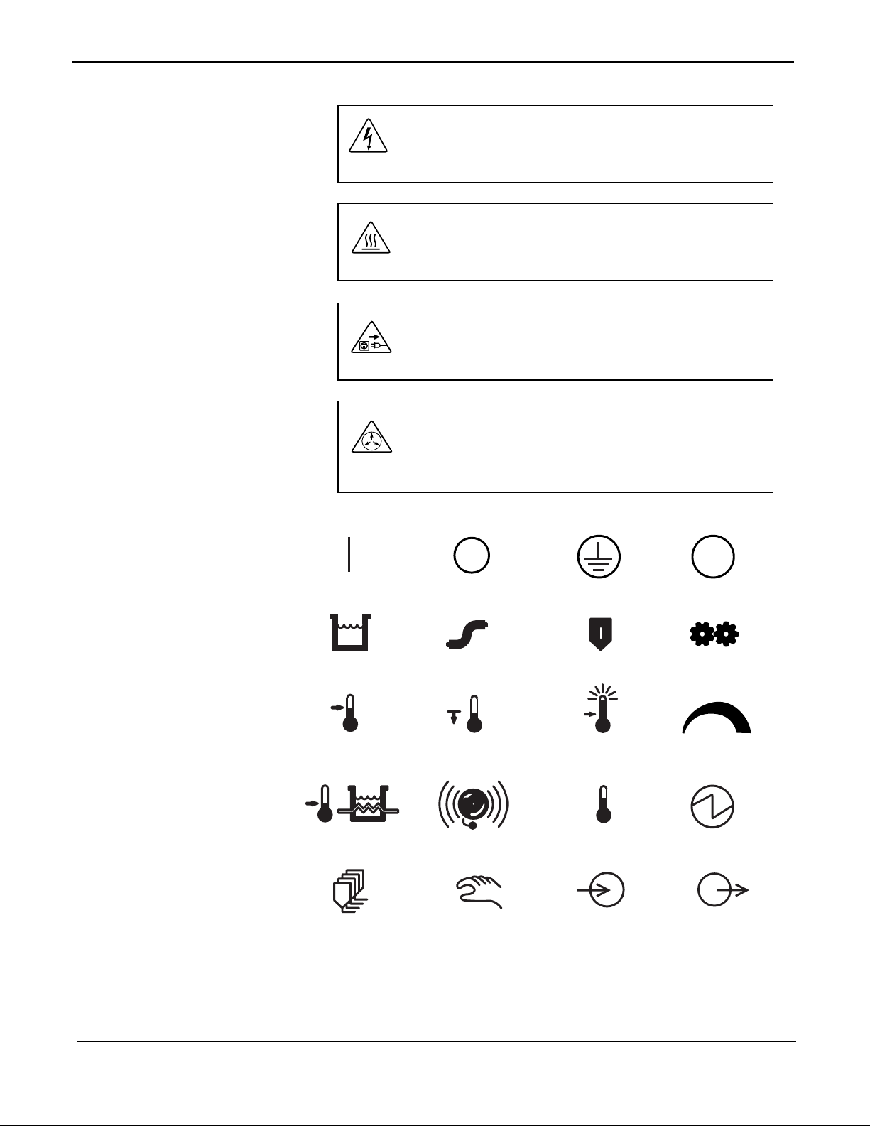
Specific Symbols and Signal Words
DANGER: High Voltage. Can cause serious
injury, including death. Disconnect electrical
power at external source before servicing
WARNING: Hot Surface. Can cause serious
injury and burns. Wear heat resistant clothing,
gloves and safety goggles.
WARNING: Disconnect electrical power at
external source. Failure to do so can cause
electrical shock.
WARNING: High Pressure. System contents
under pressure. Can cause serious injury and burns
or equipment and property damage. Relieve
pressure before servicing.
Other Product Symbols
On
Tank
Set Temp
Tank Heater
Valve Group
Heated Hose
Standby Temp
Off
Alarm
Manual Task
Ground
Applicator
Overtemp
Actual Temp
Input
PE
Protective Earth
Pump Motor
-
Adhesive Flow
Source Power
Output
+
The manufacturer reserves the right to make design changes for
product improvement. This manual may not reflect all details of
these improvements.
© Copyright 2010 Astro Packaging LS10 and LS20 19600-121 3
Page 10
2 Introduction
2.1 Description
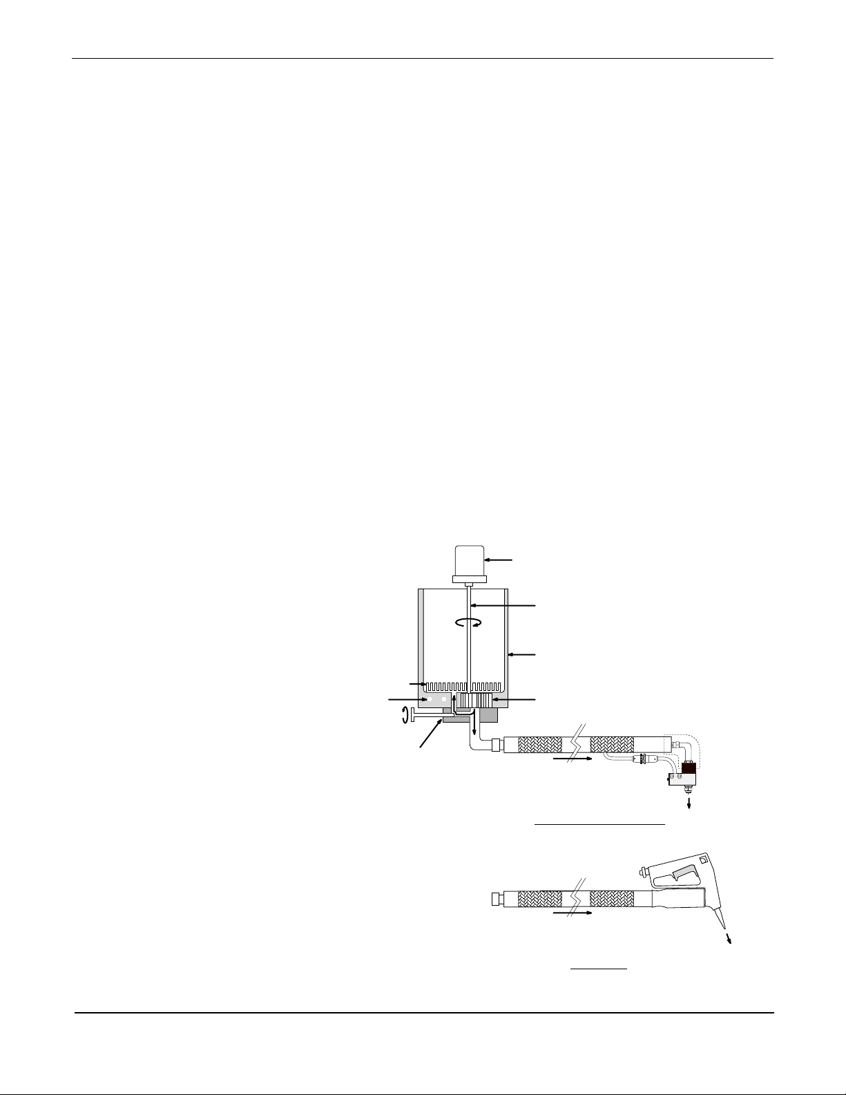
The Astro Packaging LS Series Hot Melt Unit is a light to medium
duty machine used for melting and pumping a variety of hot melt
materials. The melt unit consists of a heated melt tank and a motordriven, positive displacement gear pump.
This all-electric melt unit accepts granular, pillow, pellet or block
forms of adhesive. The LS Melt Unit is equipped with a flow
control valve for fluid pressure and flow regulation. The melt unit
is available in 10 and 20 lb tank capacities and supports 1 or 2
automatic or manual applicators and hoses.
The tank temperature ranges from ambient temperature to 205 °C
(400 °F), adjustable by a bimetallic tank temperature controller. An
internal melt grid transfers heat efficiently from the tank heaters to
the hot melt material. The melt grid is standard on the 20 lb melt
unit and an optional feature on the 10 lb tank.
Electrical power to the melt unit is controlled by a circuit breaker
located on the front panel. The electrical panel contains a terminal
block to make connections to the power-in supply circuit. See
Section 4.3: Electrical Circuits and Wiring.
Melt Grid
(Option on 10 lb)
Tank Heaters
Flow Control &
Hose Manifold Block
Drive Motor
Melt Unit
Drive Shaft
Heated Tank Reservoir
(Teflon Coated)
Positive Displacement
Gear Pump
Heated Delivery Hose
AUTOMATIC APPLICATOR
0970000
Heated Delivery Hose
HANDGUN
4 LS10 and LS20 19600-121 Copyright 2010 Astro Packaging
Page 11

2.2 Features
• System power circuit breaker protects the entire system from
overload.
• A tank-mounted overtemperature thermostat turns the tank
heaters off in the event of a tank controller failure.
• A circuit breaker protects the pump motor by turning the motor
off should a stall or overload condition occur.
• A pump warmup thermostat protects the pump-drive
mechanism by preventing motor/pump operation below 121 °C
(250 °F).
• Head firing with LS automatic melt units can be from direct
signal input or any AC or DC model of ET Series Pattern
Controllers.
• An optional filter block is available for applications requiring
adhesive filtering.
• AC power cords are supplied with 100 VAC and 115 VAC
units only.
• A “Little Squirt” is a 10-pound one or two hose manual
handgun configuration of the LS Series.
© Copyright 2010 Astro Packaging LS10 and LS20 19600-121 5
Page 12

3 Specifications
3.1 Electrical
3.2 Physical
Voltage ------------------------------ 100, 115, 200 or 230 VAC (±10%)
single phase
Power Requirements -------------- LS10: 900 W (melt unit only: hoses/
---------------------------------------- LS20: 1400 W applicators not included)
Frequency--------------------------- 50/60 Hz
Main Circuit Breaker Rating----- All VAC: 15 A
Pump Motor Circuit -------------- 200/230 VAC: 0.5 A
Breaker Rating --------------------- 100/115 VAC: 1 A
Tank Overtemperature Thermostat
---------------------------------------- 205 °C (400 °F) (standard, other ratings
available)
Pump Warmup Thermostat------- 121 °C (250 °F) (standard, other ratings
---------------------------------------- available)
Tank Capacity---------------------- LS10: 4.5 kg (10 lb)
---------------------------------------- LS20: 9.1 kg (20 lb)
Hose Capacity---------------------- 2 manual hoses or 2 automatic hoses
Shipping Weight ------------------- LS10: 29.1 kg (64 lb)
---------------------------------------- LS20: 35.4 kg (78 lb)
Storage Temperature -------------- 0–60 °C (32–140 °F)
Pump Size -------------------------- V1-450: 7.4 CCD (0.450 CID)
---------------------------------------- V1-675: 11.1 CCD (0.675 CID)
Melt Grid --------------------------- LS10: optional
---------------------------------------- LS20: standard
3.3 Operating
Warmup Time---------------------- 30–45 minutes
Viscosity ---------------------------- Maximum 25,000 centipoise (cps)
Melt Rate --------------------------- LS10: 3.6 kg/hr (8 lb/hr) - without melt
grid
---------------------------------------- LS20: 9.1 kg/hr (20 lb/hr) - with melt
grid
Temperature Range---------------- 38 °C – 232 °C (100 °F – 450 °F)
3.4 Environmental
Ambient Air Temperature -------- 5–40 °C (41–104 °F)
Altitude------------------------------ Sea level up to 2 km (1.24 miles)
Humidity ---------------------------- 30–95 R.H. (%)
6 LS10 and LS20 19600-121 Copyright 2010 Astro Packaging
Page 13
3.5 Motor Speed, Adhesive Pressure, and Flow Rate
Frequency 50-60 Hz
Motor Speed 44/min (rpm)
Recommended Adhesive
Pressure Range*
V4-675 Pump 6.89–20.68 bar
689.48–2,068.43 kPa
100–300 psi
Maximum Flow Rate*
V1-675 Pump 25 kg/hr 21 kg/hr
55 lb/hr 45 lb/hr
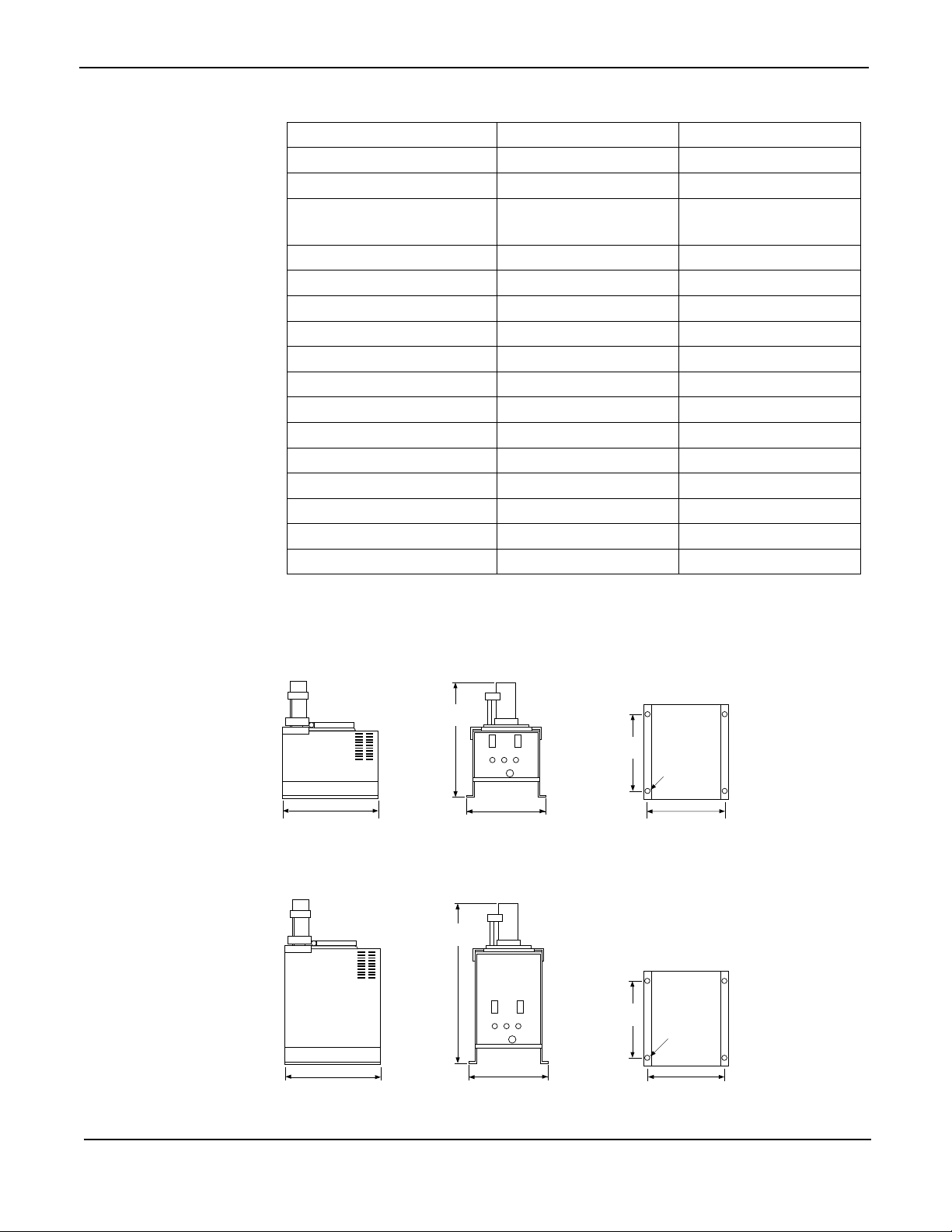
3.6 Dimensions
*Based on standard, packaging grade hot melts at 1000 cps. Varies with
adhesive and tank temperature. Consult factory representative for nonstandard requirements.
508 mm
(20 in.)
269.7 mm
355.6 mm (14 in.)
LS10 Hot Melt Unit
698.5 mm
(27.5 in.)
342.9 mm (13.5 in.)
(10.62 in.)
269.7 mm
(10.62 in.)
6.3 mm
(0.25 in.) dia.
317.5 mm (12.5 in.)
6.3 mm
(0.25 in.) dia.
0960149a
0970014
355.6 mm 14 in.)
342.9 mm 13.5 in.)
317.5 mm (12.5 in.)
LS20 Hot Melt Unit
© Copyright 2010 Astro Packaging LS10 and LS20 19600-121 7
Page 14

4 Installation
4.1 Setup
1. Remove all packaging material around melt unit.
2. Carefully lift melt unit out of box.
3. Unpack the binder containing product manuals, electrical
schematic, warranty information and flow control valve hex
wrench. Retain binder for future reference.
4. Unscrew 4 screws from plywood board base; remove and
discard plywood.
5. Carefully uncoil hoses from around melt unit and remove
protective wrap from applicators. Inspect all packing material
for separately wrapped items.
6. Position melt unit for easy access to control panel and
convenient servicing.
7. Level mounting surface to prevent warping of melt unit and to
avoid misalignment of the pump and motor shaft.
8. Using the base mounting holes, bolt melt unit down to a
durable mounting surface in accordance with dimensions in
illustrations in Section 3.6 to prevent accidental upset and
possible injury.
9. Tighten all screws before startup and after melt unit
experiences excessive vibration.
8 LS10 and LS20 19600-121 Copyright 2010 Astro Packaging
Page 15

4.2 Component Installation
4.2.1 Manual (Handgun) Systems
All standard components are normally installed on the melt unit at
the factory with no user installation required. If not installed, refer
to Hose Replacement. Refer to handgun product manual for
complete information on installation and service of the
handgun/hose assembly.
4.2.2 Automatic Systems
Hoses
Hoses are normally installed on an automatic melt unit at the
factory with no user installation required. If not installed, refer to
Hose Replacement. Refer to heated supply hoses product manual
for complete installation and service information.
Automatic Applicators (Heads)
Automatic applicators may be attached to hoses or packaged
separately. If not installed, proceed as follows:
1. With system power off, attach hose output electrical connector
to applicator. Heat fluid fittings on applicator and output end
of hose by attaching the electrical connector and applying
power for 3–5 minutes or until hose fitting will rotate.
2. Connect output end of the hose to adhesive input fitting on the
applicator.
3. When system reaches operating temperature, retighten all
adhesive connections. Check for leaks.
Refer to applicator product manual for installation and service
information.
Pattern Controllers, Head Drivers and Optional External
Components
Pattern controllers, head drivers and other external components
normally need to be connected to melt unit during installation.
Refer to electrical schematic, located in manual binder or back of
melt unit, for appropriate wire connections to the melt unit. Refer
to individual component product manual for complete installation
and service information.
© Copyright 2010 Astro Packaging LS10 and LS20 19600-121 9
Page 16

4.3 Electrical Circuits and Wiring
4.3.1 Electrical Schematic
Consult the electrical schematic provided with the melt unit for all
wire connections and component interconnections. Schematics are
shipped with each system and are found in the binder with the
product manuals. A copy of the schematic should remain with the
melt unit at all times.
4.3.2 Power Requirements
!
The LS Melt Unit uses single phase 100,115, 200, or 230 VAC
power sources, each with earth ground for safety. Refer to
illustration below for terminal block configuration. The standard
230 VAC melt units are wired for 2-wire single phase power. An
identification plate is attached to each melt unit on the outside rear
door of the tank housing. This plate specifies the exact voltage of
the melt unit and frequency of the pump motor. Pump motor
voltage, frequency and current are specified on the motor data
plate located on the motor. For safe and proper installation, refer to
the identification plate before applying electrical power to the melt
unit.
CAUTION: Power conducting wires must be rated
for intended current and 75 °C (167 °F).
4.3.3 Electrical Connections
Standard 230 VAC Single Phase, 2 Wire
L1
115
115 VAC Single Phase
L1
115
100 VAC Single Phase
L1
100
200 VAC Single Phase, 2 Wire
L1
100
L2 Ground
230
115
Neutral Ground
115
Neutral Ground
100
L2 Ground
200
100
0960358a
10 LS10 and LS20 19600-121 Copyright 2010 Astro Packaging
Page 17

4.3.4 Power-in Wiring
100–115 VAC
The melt unit comes equipped with an 2.44 m (8 ft) power cord,
unless it is a conduit model.
200–230 VAC
1. Inspect melt unit identification plate and inside electrical panel
to verify actual capacity and type of 230 VAC power plug
required for the system (2- or 3-wire).
2. Open front control panel.
3. Install appropriate power-in 16 AWG wires in the terminal
blocks provided. For automatic systems only, also configure
and install applicator program wires and jumpers. Refer to
Terminal Block Configuration diagram. Liquidtight conduit
and fittings are recommended when routing wires to electrical
terminal blocks. Holes in the chassis are provided for these
installations.
4. Close the front control panel after electrical hookup.
4.3.5 Valve Group Control Circuits for Automatic
Systems
An automatic applicator, or valve, contains one or more adhesive
valves which are activated by a solenoid. A valve group is a
number of valves powered by the same source which activate at
the same time. There are several options to activate electric valves
and valve groups:
Two Types of Valves and Firing Circuits
Automatic applicators are specified by solenoid voltage and valve
type. Valves must match the VAC or VDC firing voltage. Multiple
valve applicators may have more than one firing circuit within a
single applicator.
© Copyright 2010 Astro Packaging LS10 and LS20 19600-121 11
Page 18

4.3.6 VAC Valve Firing Voltage
Firing Voltage
Source
Melt unit any VAC
External customer
External customer
External customer
* Timer adaptor relay isolates melt unit power from an external
power source
Trigger Signal
Source
trigger
VAC trigger
VAC trigger
VDC trigger
Optional Timer
Adaptor Relay *
no relay present
no relay not present
AC relay present
DC relay present
Pattern Control
Jumpers
4.3.7 VDC Valve Firing Voltage
Firing Voltage
Source
DC Head
Driver
Trigger Signal
Source
any 3–32
VDC trigger
Head Driver
Required
DC Head Driver not present
Pattern Control
Jumpers
4.3.8 Foot Switch Trigger for Semi-automatic Systems
A manually operated foot switch allows operator to control
adhesive deposition through automatic applicators while keeping
hands free. The foot switch assembly may be factory installed or
added later. See Section 9.7: Accessories.
12 LS10 and LS20 19600-121 Copyright 2010 Astro Packaging
Page 19

4.3.9 External Control of Pump Motor for Automatic
Systems
The pump motor circuit may be connected to a parent machine or
other control device to enable the parent machine to control the hot
melt system pump. This extends pump life and provides added
safety when the melt unit is used in conjunction with other
machinery.
1. Using melt unit electrical schematic, locate parent machine
interface jumper.
2. Remove parent machine interface jumper.
3. Wire contacts from external device to the melt unit main
terminal block where the parent machine interface jumper was
located.
© Copyright 2010 Astro Packaging LS10 and LS20 19600-121 13
Page 20

5 Operation
5.1 Controls and Indicators
DANGER: Disconnect power before opening front
!
panel. Hazardous voltage can shock, burn, or cause
death.
Please read and see illustration opposite before operating melt unit.
[1] System Power Switch/Circuit-Breaker and Indicator Light
A magnetic type breaker opens the circuit when current exceeds 15
A. The system power switch illuminates white when in ON
position.
[2] Overtemperature Indicator Light
Illuminates red and ceases power to the tank heaters when melt
tank temperature exceeds thermostat rating. In the event of an
overtemperature condition, turn down tank temperature with
control or replace control if defective. See Section 7: Troubleshooting.
[3] Tank Thermometer
Indicates temperature of hot melt material in the melt tank. The
hose temperature adjustment, located behind front panel, indicates
the set temperature of the material in the hose.
[4] Tank Heating Indicator Light
Illuminates amber when tank heaters are powered and assists user
in making temperature adjustments to tank temperature controller.
[5] Pump Motor ON/OFF Breaker Switch
Turns off pump motor during system warmup or system
maintenance. A circuit breaker in the pump motor circuit protects
motor during a stall or overload condition.
[6] Pump Warm-Up Thermostat (Not Shown)
This close-on-rise thermostat prevents the motor from running
before system reaches operating temperature.
14 LS10 and LS20 19600-121 Copyright 2010 Astro Packaging
Page 21

APPLICATOR
POWER
1
5
2
0960130b
PUMP
ON
OFF
HEATING
TANK
OVERTEMP
TEMPERATURE
34
© Copyright 2010 Astro Packaging LS10 and LS20 19600-121 15
Page 22

5.2 Start-up
1. Become familiar with Section 5.1: Controls and Indicators.
2. Install melt unit as specified in Section 4.
3. Fill tank with hot melt material to 38 mm (1.5 in.) from top.
4. Turn unit on and allow 30 minutes warmup time.
5. Align the motor, if necessary. Motor alignment is necessary on
receipt of a new unit or after transportation; when replacing
the motor, pump-shaft, bearing block, or pump; or when the
motor is noisy.
a. Loosen the screws holding the motor.
b. Warm up melt unit and run the motor. This causes the
motor to center itself.
c. With motor running, tighten screws in a crisscross pattern.
6. Set hose and tank temperature to desired settings. Lower
settings will increase the material pot life.
7. Set the tank temperature as low as possible for each
application. Certain materials degrade over time due to
oxidation.
8. To prevent stalling the motor, adjust flow control valve to
minimum flow requirement.
16 LS10 and LS20 19600-121 Copyright 2010 Astro Packaging
Page 23

5.3 Adjustments
5.3.1 Temperature Adjustments
Hose Temperature Controller
Temperature graduations on hose controllers reflect approximate
hose temperature.
1. For precise readings, measure inside hose temperature with a
pyrometer and bead probe. Hose temperature should be the
minimum temperature required for application to prevent
degradation of material in the hose and maximize hose life.
2. To raise hose temperature, turn knob [2] in illustration below
clockwise to desired temperature.
3. To lower hose temperature, turn knob [2] counterclockwise to
desired temperature.
4. Refer to Temperature Check in Maintenance section of the
Astro Packaging Heated Hose Manual.
Tank Temperature Controller
1. To prevent hot melt degradation, set melt tank temperature to
the minimum temperature specified by the hot melt
manufacturer.
2. To raise melt tank temperature, turn tank temperature
controller adjustment shaft [1] in illustration below clockwise
with screwdriver.
3. To lower melt tank temperature, turn adjustment shaft [1]
counter-clockwise with screwdriver. The melt tank
temperature controller ranges 260 °C (500 °F) in one 320°
rotation of the adjustment shaft.
4. Verify temperature on tank thermometer.
5. Allow melt tank temperature to stabilize 30 minutes before
adjusting further. See Section 3: Specifications for melt tank
temperature range.
2
1
© Copyright 2010 Astro Packaging LS10 and LS20 19600-121 17
Page 24

5.3.2 Flow Adjustments
WARNING: High Pressure. System contents under
pressure. Can cause serious injury and burns or
equipment and property damage. Relieve pressure
before servicing.
CAUTION: For maximum performance and motor
!
life, do not allow pump motor to stall. A prolonged
stall condition will cause motor to go into thermal
overload.
Flow Control Valve
An adjustable pressure regulating device is mounted on the pump
under the melt unit chassis. See illustration below.
1. Adjust flow control from the lower right side of melt unit
using the hex wrench supplied with unit.
2. To increase pressure, turn hex wrench clockwise.
3. To decrease pressure, turn hex wrench counterclockwise.
4. To achieve minimum pressure and lowest flow rate, turn hex
wrench fully counterclockwise.
5. Gradually turn hex wrench clockwise until desired pressure
and flow rate is reached.
Increase
Decrease
0960141a
Hex
wrench
18 LS10 and LS20 19600-121 Copyright 2010 Astro Packaging
Page 25

6 Maintenance
WARNING: Hot melt materials can cause severe burns
!
resulting in disfigurement or blindness. Take the
following precautions before beginning any
maintenance:
• Wear protective clothing, safety goggles, and safety
gloves.
• Turn pump motor switch off position. Depressurize
applicator(s) by triggering.
• Unless stated otherwise, always allow melt unit to
cool before beginning any maintenance.
• Disconnect hose electrical connector when hose
fittings are disconnected and power is off.
CAUTION: To prevent damage to components (hose
!
fittings, etc.), heat part(s) being serviced to
approximately 121 °C (250 °F) prior to dismantling,
assembling, or adjusting. Heat parts by applying power
to the unit using a hand held hot air gun or placing parts
on a hot plate. Failure to do this will result in stripped
threads and ruining both parts and tools.
CAUTION: To avoid arcing of electrical contacts and
!
possible failure of components, do not connect
electrical connectors when the hose power switch is on.
© Copyright 2010 Astro Packaging LS10 and LS20 19600-121 19
Page 26

6.1 Preventive Maintenance
Procedure Daily Monthly As
Required*
Check for foreign material in
tank.
Wipe off excess hot melt from
cover.
Check for leaks. X
Purge tank and hoses. X X
Inspect hoses. ** X
Check tank temperature. *** X
Clean applicator nozzles. X
* Extra maintenance required for continuous duty machines.
** Verify hose is properly supported so it is not stressed during
use. Minimum bend radius is 8 in. when hot.
Check temperatures.
Adjust temperature according to Hose Temperature Controller
section. On multi-hose systems, a temperature difference
between hoses is quickly noted by touching outer insulation of
each hose.
*** Verify system is not operating in overtemperature mode by
observing Overtemperature Indicator Light.
Determine tank temperature and adjust as explained in Tank
Temperature Controller section.
X
X
20 LS10 and LS20 19600-121 Copyright 2010 Astro Packaging
Page 27

7 Troubleshooting
Problem Solutions
Tank does not heat
Tank heats slowly
Tank overtemperature
Applicator and hose heat slowly
1. Turn on main power breaker switch. If switch light
fails to illuminate, replace switch.
2. Inspect power-in connections for proper fit.
3. Check for faulty wires.
4. Inspect power wires or power plug at main power
source.
5. Check supply voltage to melt unit with voltmeter.
The voltage of each component must equal the
supply voltage or system damage will occur.
6. Check incoming control voltage to terminal blocks.
7. Check tank controller for proper operation.
8. Check wire connections against electrical schematic
to ensure melt unit is properly wired.
9. If problem still exists, replace tank heaters as
specified under Tank Heater Replacement.
1. Check status of components with a voltmeter
(system powered) or ohmmeter (system unpowered,
wires disconnected).
2. Adjust tank temperature controller. Inadequate tank
heat can affect performance.
3. If problem still exists, replace tank heaters as
specified under Tank Heater Replacement.
1. Check tank temperature when overtemp indicator is
lit. If too high, turn tank controller counterclockwise
to reduce temperature. If light is on at acceptable or
low temperature, switch is faulty or rated at a low
temperature. Replace overtemperature switch.
1. Adjust hose and applicator temperature controllers.
Inadequate heat can affect performance.
2. Verify hose electrical connector is properly
connected.
3. Check supply voltage to hose controller with volt
meter.
4. If problem persists, refer to Hose Controller
Replacement.
© Copyright 2010 Astro Packaging LS10 and LS20 19600-121 21
Page 28

Problem Solutions
Applicator and hose fail to heat
Adhesive output too high
Adhesive output too low
1. Check incoming hose power connector to see if
properly installed. Connector wire pins may be
misaligned or loose.
2. If no change, disconnect incoming hose power
connector and check hose heater resistance with
ohmmeter. If hose heater fails, replace hose. See
Slautterback Heated Hose Manual.
3. Determine if applicator is heating by using a
pyrometer or temperature sensing device. Do not
touch applicator by hand to determine temperature.
Refer to the handgun manual.
1. Decrease system fluid pressure with flow control
valve. If no change, remove nozzle and replace with
a smaller orifice nozzle.
2. Decrease hose temperature by 4–10 °C (25–50 °F).
If no change, consult your hot melt material vendor
regarding application.
1. Increase system fluid pressure without stalling the
motor by adjusting flow control valve. If no change,
remove nozzle and replace with a larger orifice
nozzle
2. Clean applicator nozzle.
3. Purge system.
4. Increase hose temperature by 4–10 °C (25–50 °F). If
no change, consult your hot melt material vendor
regarding application.
5. Hot melt formulations tend to be a factor in
previously listed problems. Refer to Start-up for
cautions.
• If troubleshooting attempts fail, please contact your distributor.
22 LS10 and LS20 19600-121 Copyright 2010 Astro Packaging
Page 29

8 Repair and Replacement
See Parts List, in Section 9, for all replacement parts listed in this
section.
8.1 Hose Replacement
a. Removal
1. Switch system power off, and allow hot melt in tank to
2. Switch system on for 5 minutes to allow fittings to warm or
3. Switch system power off, and disconnect melt unit electrical
4. Per illustration below, disconnect hose electrical connector [2]
CAUTION: For safe and proper hose replacement,
!
verify that all material in melt tank has completely
solidified.
completely solidify.
heat fitting with a hand-held hot air gun.
power from external source.
by tilting melt unit back until underside is accessible. Support
the melt unit with block on back of housing so hot melt does
not spill. Do not turn melt unit upside down.
5. Remove screws from hose mounting block [1].
6. Loosen hose JIC fitting [5] and remove hose from the
fitting [4] on the flow control block [3].
5
4
3
1
2
© Copyright 2010 Astro Packaging LS10 and LS20 19600-121 23
Page 30

b. Replacement
1. Switch off system power and disconnect melt unit electrical
power from external source.
2. Never flex a hose when cold. Hoses have a minimum bend
radius of 20.32 cm (8 in.) when hot. Further flexing will cause
permanent damage.
3. Per illustration below, heat hose JIC fittings [5] before
adjusting or damage may result. New or clean hose fittings
may not require heating.
4. Install hoses on melt unit by tilting melt unit back until
underside is accessible. Support melt unit with block on back
of housing so hot melt does not spill. Do not turn melt unit
upside down.
5. Support hose to prevent excessive flexing. Do not support
hose in a way which may add to its thermal insulating
characteristics or overheating will result. Failure to properly
support the hose will result in premature failure.
6. Install hose as follows:
a. Loosely connect the hose JIC swivel fitting [5] to
fitting [4] on the flow control block or hose manifold [3].
b. Fasten hose support block [1] to chassis.
c. Tighten JIC swivel fitting [5].
d. Attach hose electrical connector [2].
e. Tuck electrical connector under melt unit.
f. Position and support hose before using.
g. After heating, tighten JIC swivel fitting [5].
5
4
1
2
3
24 LS10 and LS20 19600-121 Copyright 2010 Astro Packaging
Page 31

8.2 Hose Controller Replacement
1. Turn off system power and allow hot melt in tank to
completely solidify.
2. Turn system power back on for five minutes to allow fittings to
warm up, or heat fittings with a hand-held hot air gun.
3. Turn off system power and disconnect melt unit electrical
power.
4. Tilt melt unit backward.
5. Loosen hose JIC fitting and remove hose from fitting on flow
control valve.
6. Remove thermostat bulb from hose end; take care not to kink
capillary tube.
7. Open front control panel.
8. Disconnect controller wires.
9. Remove screws fastening controller to electrical panel.
10. Install new controller.
a. Insert thermostat bulb into hose end.
b. Coil capillary tube so it hangs in a suitable position under
chassis.
11. Reconnect hose to JIC as specified in Section 4.2: Component
Installation.
12. Reconnect melt unit power, turn on power switch, and adjust
controller as specified in Section 5.3.1.
© Copyright 2010 Astro Packaging LS10 and LS20 19600-121 25
Page 32

8.3 Tank Heater Replacement
1. Before considering replacement, check each heater with amp
2. To measure heater resistance, switch off system power and
3. Per illustration below, open control panel and remove tank
4. Determine resistance of each individual heater [2]. Refer to
5. If heater requires replacement, disconnect wires of defective
6. Pull heater out of bore using pliers. If heater does not come
7. Apply a coating of heat release and transfer agent to new
probe (system power on) or ohmmeter (system power off,
wires disconnected). Refer to electrical schematic, located in
back of melt unit.
disconnect electrical power from external source.
access panel [1].
Appendix A for Component Resistance Tables.
heater.
out easily, drive out using a 6.35 mm (0.25 in.) diameter rod
inserted in knockout holes in back of tank base.
heater and slide it into tank heater bore from the front.
8. Route heater lead wires through electrical panel, and reconnect
heater wires in original locations. See electrical schematic
included with melt unit.
9. Replace tank access panel.
10. Close and fasten control panel.
1
2
26 LS10 and LS20 19600-121 Copyright 2010 Astro Packaging
Page 33

8.4 Tank Controller Replacement
1. Disconnect melt unit electrical power.
2. Open front control panel.
3. Remove tank access panel at bottom of electrical panel.
4. Remove wires connected to thermostat. Tank thermostat
controller is the elongated thermostat mounted horizontally on
the tank base plate.
5. Remove screws holding tank thermostat to tank.
6. Apply even coating of heat sink compound to base of the new
thermostat.
7. Attach replacement thermostat to the tank assembly using the
mounting clip and screws. Reconnect wires.
8. Replace tank access plate.
!
WARNING: Failure to replace the access plate will
result in an electrical hazard and possible heat damage
to electrical components.
9. Close front control panel.
(800-401-1441
© Copyright 2010 Astro Packaging LS10 and LS20 19600-121 27
Page 34

8.5 Hose Manifold Filter Block Replacement or Cleaning
The hose manifold filter block is an optional component that is
required when a pump filter is used.
1. If possible, pump out all adhesive in melt unit before
disconnecting power. If not possible, disconnect power and
allow hot melt in tank to solidify.
2. Switch on system power for 5 minutes to warm fittings.
3. Switch off system power and disconnect electrical power at
external source.
4. Disconnect hose electrical connector and tilt melt unit
backwards. Support the melt unit with block on back of
housing so hot melt does not spill. Do not turn melt unit
upside down.
5. Per illustration below, loosen JIC fittings [5] and remove
hose(s) from fitting(s) [6] on hose manifold [3].
6. Remove screws [4] from hose manifold filter block [3].
7. Ease hose manifold [3] from flow control block [1]. Two
screws remain (3 for reverse mounting) holding flow control
block [1] and pump to tank base plate.
8. Clean hose manifold [3] thoroughly, especially flow control
block mating surface, or replace with a spare hose manifold.
9. Refit hose manifold [3] with hardware. After lubricating with
a silicone-based grease such as DC 5, replace o-rings [2].
10. Switch on system power, and allow melt unit to reach
operating temperature.
11. Reconnect hose as specified in Hose Replacement.
1
2
3
6
5
4
0950175
28 LS10 and LS20 19600-121 Copyright 2010 Astro Packaging
Page 35

y
8.6 Pump Filter Installation, Servicing, and Replacement
A pump filter is an optional accessory for use when adhesive
filtering is desired. The pump filter is installed in the hose
manifold filter block. See illustration below for installation and
servicing the filter element.
WARNING: Contents at high temperature and
pressure. Remove pressure before opening filter or
drain valve to prevent accidental discharge of system
pressure. Do not touch hot surfaces. Failure to follow
these instructions ma
1. Bring melt unit to operating temperature.
2. Switch off pump motor.
3. Activate applicator several times to relieve all pressure in the
system.
4. Place a disposable container below filter access area to catch
all adhesive spillage or run off.
5. Slowly remove plug [1] with o-ring [2] to release any residual
pressure trapped in hose manifold filter block [6]. A 9/16 in.
hex wrench is required.
result in severe burns.
6. Remove spring [3], spring retainer [4], and filter [5]. Clean all
parts.
7. Carefully switch pump motor on for approximately 1 to 2
seconds causing a small amount of adhesive to flush the filter
chamber. Clean filter chamber of all foreign material. Repeat
if necessary.
8. Insert spring retainer [4] and spring [3] into clean filter [5].
Place clean filter assembly into manifold filter block [6].
9. Inspect o-ring [2], and replace if damaged.
10. Install plug [1] with o-ring [2] securely into hose manifold
filter block [6].
5
6
4
3
2
1
© Copyright 2010 Astro Packaging LS10 and LS20 19600-121 29
Page 36

8.7 Pump Motor and Pump Shaft Assembly Replacement
1. Disconnect electrical power and allow melt unit to cool to
121 °C (250 °F).
2. Per illustration below, open motor junction box cover [1],
disconnect wiring and liquidtite fitting [2].
3. Remove screws [4] holding motor mounting plate to melt unit.
4. Lift motor assembly off melt unit.
5. Inspect motor shaft coupler [3] for wear. Replace if necessary.
6. If not replacing shaft assembly, skip to Step 8. If replacing
pump shaft assembly or individual shaft assembly parts,
remove bronze spider [6], coupler and key [11 and 12],
washer [7], retaining ring [10], and shaft [8], and shaft
retainer [9].
7. Install new shaft assembly or individual components as
needed.
8. Remove screws [5] holding pump motor to motor mounting
plate [13].
9. Install new pump motor on motor mounting plate.
10. Check pump shaft alignment on pump in tank.
11. Align motor coupling [3] with pump shaft in tank and lower
onto shaft.
12. Align motor mounting plate to melt unit with mounting
screws [4].
13. Verify that pump shaft seats properly with pump, and verify
that coupler clearance [14] of 0.8 mm ±0.3 mm (0.030 in.
±0.010 in.) exists.
14. Replace liquidtite fitting and wires [2].
15. Reconnect wires according to electrical schematic, located in
back of melt unit. Refer to melt unit identification plate to
determine exact voltage.
16. Turn on melt unit and allow melt unit to heat to normal
operating temperature. Turn on pump motor.
17. Tighten screws [4] in a crisscross pattern while motor is
operating to align pump shaft.
18. If replacing complete motor group, also replace pump motor
switch on front panel and motor capacitor inside electrical
enclosure.
30 LS10 and LS20 19600-121 Copyright 2010 Astro Packaging
Page 37

1
2
14
3
4
13
4
5
6
7
0950178
11, 12
10
8
9
© Copyright 2010 Astro Packaging LS10 and LS20 19600-121 31
Page 38

9 Parts List
9.1 Control Panel - Front View
Item Description (Quantity) Part Number
1 Circuit breaker/switch, main 15 A 115 VAC 12015-1
1 Circuit breaker/switch, main 15 A 230 VAC 12015-3
2 Lamp, round red (overtemperature indicator) 12030-1
3 Thermometer 11029
4 Thermometer, spring 14488-1
5 Lamp, round amber (tank heating indicator) 12030-10
6 Circuit breaker/switch, pump motor, 1 A (100/115 VAC unit) 12055-1
6 Circuit breaker/switch, pump motor, 0.5 A (200/230 VAC unit) 12055-3
APPLICATOR
POWER
1
6
2
0960130c
PUMP
ON
OFF
HEATING
TANK
OVERTEMP
TEMPERATURE
3, 45
32 LS10 and LS20 19600-121 Copyright 2010 Astro Packaging
Page 39

9.2 Electrical Enclosure and Chassis Base
Item Description (Quantity) Part Number
1 Tank heater kit, 115 VAC, 400 W (2 heaters for 10 lb. unit) 79005
1 Tank heater kit, 230 VAC, 400 W (2 heaters for 10 lb. unit) 79005-1
1 Tank heater kit, 100 VAC, 400 W (2 heaters for 10 lb. unit) 79005-2
1 Tank heater kit, 200 VAC, 400 W (2 heaters for 10 lb. unit) 79005-3
1 Tank heater kit, 230 VAC, 600 W (2 heaters for 20 lb. unit) 79044
1 Tank heater kit, 115 VAC, 600 W (2 heaters for 20 lb. unit) 79044-1
1 Tank heater kit, 100 VAC, 600 W (2 heaters for 20 lb. unit) 79044-2
1 Tank heater kit, 200 VAC, 600 W (2 heaters for 20 lb. unit) 79044-3
2 Tank controller, kit 38–232 °C (100–450 °F) 79006
3 Panel, access 70350-1
4 Connector 9-pin, for solid capillary controlled melt units 12115-9
5 Flange, 9-pin connector, panel mount 12115-10
6 Female electrical pins 12116
7 Hose controller, kit 38–93 °C (100–200 °F) 79125-1
7 Hose controller, kit 93–149 °C (200–300 °F) 79125-2
7 Hose controller, kit 149–204 °C (300–400 °F) 79125-3
7 Hose controller, kit 177–232 °C (350–450 °F) 79125-4
7
1
1
6
2
3
4
5
© Copyright 2010 Astro Packaging LS10 and LS20 19600-121 33
Page 40

9.3 Motor Group and Pump Shaft Assembly
Item Description (Quantity) Part Number
2 Motor assembly, 44/36 rpm, 50/60 Hz, 100/115 VAC 73012-32
3 Capacitor, 3 µf, 370 VAC, flat pack 12045-3
4 Circuit breaker/switch, pump motor, 1 A (100/115 VAC unit) 12055-1
4 Circuit breaker/switch, pump motor, 0.5 A (200/230 VAC unit) 12055-3
5 Key, motor coupler to pump shaft 14475-18
6 Coupler, HF&FS, 1/2 in. w/ keyway 70460-2
7 Spacer, AL. 10 x .50 x 1.25 LG 14471-6
8 Washer, lock 14451-FA
9 Screw, socket head cap 10-32 x 1.75 LG 14431-FDO
10 Screw, set flat point, 1/4 - 28 x 3/16 14401-HDB
11 Pump shaft assembly, 10 lb. melt unit 73726-21
11 Pump shaft assembly, 20 lb. melt unit 73726-22
12 Washer, rat trap 14528-4
13 Retaining ring 14502-12
14 Shaft, pump with keyway, 10 lb. melt unit 70461-3
14 Shaft, pump with keyway, 20 lb. melt unit 70461-4
15 Retaining spring pump shaft 70028
Retainer seal for pump shaft 70028-1
Kit, gearbox repair, 44/36 rpm motor 79295-01
Wire nuts (medium low temperature) 12277-2
* Motor group includes Motor Assembly, Capacitor, Pump “ON/OFF” breaker, and hardware.
2
3
4
5
10
6
7
8
9
11
12
13
14
15
34 LS10 and LS20 19600-121 Copyright 2010 Astro Packaging
Page 41

9.4 Pump Warm-up and Tank Overtemperature Thermostats
Item Description (Quantity) Part Number
LS10, LS20 Pump Warm-up Thermostat Kit
1 37.78 °C (100 °F) 79068-100
1 93.33 °C (200 °F) 79068-200
1 107.22 °C (225 °F) 79068-225
1 129.44 °C (265 °F) 79068-265
1 148.89 °C (300 °F) 79068-300
1 176.67 °C (350 °F) 79068-350
LS10 Overtemperature Thermostat Kit
2 65.56 °C (150 °F) 79126-150
2 93.33 °C (200 °F) 79126-200
2 148.89 °C (300 °F) 79126-300
2 204.44 °C (400 °F) 79126-400
2 232.22 °C (450 °F) 79126-450
LS20 Overtemperature Thermostat Kit
2 65.56 °C (150 °F) 79127-150
2 93.33 °C (200 °F) 79127-200
2 148.89 °C (300 °F) 79127-300
2 204.44 °C (400 °F) 79127-400
2 232.22 °C (450 °F) 79127-450
0960370
2
1
1
2
© Copyright 2010 Astro Packaging LS10 and LS20 19600-121 35
Page 42

9.5 V4 Pump, Flow Control Valve, and Hose Manifold Filter
Item Description (Quantity) Part Number
1 Pump seal kit, all V4 pumps 79081
2 Pump Kit, V4-675, 0.675 CID flange thickness = 15.9 mm (0.625 in.) 79290-2
3 Washer, lock, 0.25 in. 14451-GA
4 Screw, socket head cap 1/4-20 x 2.5 in. (for V4-675) 14431-GDQ
5 Flow control valve replacement kit, 1 hose 79025-4
5 Flow control valve replacement kit, 2 hose 79082-4
5 Flow control valve replacement kit, for units with filter block 75011-010
6 Flow control valve repair kit, 2 hose 79082-2
7 Flow control valve replacement 79082-8
8 Spring, flow control valve 14489-10
9 Damper, flow control valve 70392-1
10 Plug, 1/4 NPTF, flush, steel 11603-4D
11 Hex wrench 1/4 in. 11050-1/4
12 Pump filter kit, 50 mesh 79064
13 Plug, socket head No. 12, with o-ring 10456, for filter chamber 11604-12
14 O-ring for 11604-12, viton, 0.116 in. W x 0.924 in. 10456
15 Filter block, kit, 1 hose (for rear entry only), optional 79133-01
15 Filter block, kit, 2 hose (for rear exit only), optional 79133-02
16 Plug, 3/8 NPTF, steel 11603-6A
17 Fitting, male, 1/4 in. NPT to No. 6 JIC, straight 11408-64A
18 Screw, socket head cap 1/4-20 x 2.50 in. (both pumps) 14431-GDR
19 Screw, socket head cap 1/4-20 x 3.75 in. (for V1-450) 14431-GDV
19 Screw, socket head cap 1/4-20 x 4.25 in. (for V1-675 14431-GDY
20 Hose manifold filter block 70122
21 O-ring, viton, 0.86 in. ID x 0.070 in. for hose manifold filter block 10420
36 LS10 and LS20 19600-121 Copyright 2010 Astro Packaging
Page 43

© Copyright 2010 Astro Packaging LS10 and LS20 19600-121 37
Page 44

9.6 Accessories
Item Description (Quantity) Part Number
Melt Grid, for LS10
(included as standard equipment on LS20)
79033-1
Kit, Gun Hanger 79023
Filter Block Assembly - 1 hose
Filter Block Assembly - 2 hoses
Kit, Pump Inlet Screen
Kit, Pump Filter
(use with pump Filter Block Assembly
(used with a melt grid)
Kit, Reverse 1 Hose Mounting
Kit, Reverse 2 Hose Mounting
(recommended for adhesive filtering)
(recommended for adhesive filtering)
) 79064
(Filter Block Assembly not included
(Filter Block Assembly not included
79133-01
79133-02
79282-01
) 79135-10
) 79135-11
Kit, Knob Assembly FCV, V1 Retrofit to existing units 79287-01
1 B
oom 99786-B
2 Base 99786-A
3
Hose Hammock
73464-9
4 Tension Balancer, Hose, 5 Lb RF-8
5 Hose Boom & Balancer Assembly 99786
Power Cord Assembly, 115 VAC 73712-12
Kit, Hose Mole (use for in place cleaning of hoses) 79281-01
Kit, Tank Thermometer 79014
1
4
3
2
5
38 LS10 and LS20 19600-121 Copyright 2010 Astro Packaging
Page 45

Appendix A: Component Resistance Tables
Minimum and maximum resistance (R) of common melt unit components, hoses, and applicators.
Unless otherwise specified, resistance values are measured at 20° + 5° C (68° + 10° F).
Table 1. Tank Heater Resistance
Spare Kit Voltage Heater Ohms*
79005 115 12532 32.4–37.8
79005-1 230 12538 136.8–158.4
79044 230 12546-1 91–106
79044-1 115 12456-2 23–26
79088-30 230 12600 55–63.3
79088-50 230 12600 55–63.3
79088-100 230 12610 91.5–100.5
*Resistance shown is for one heater only. Spare kit may include more than one heater.
Table 2. Motor Resistance
Melt Unit Model Motor Label Spare Motor Group RPM Hz Voltage Ohms
SS10G, Mark II 73714-24 73714-24 38/31 50/60 100–115 6
SS10G, Mark II 73714-24 73714-24 38/31 50/60 200–230 16
LS/SQ10 & 20 73795-01 73714-20 44/36 50/60 100–115 25–28
LS/SQ10 & 20 73795-02 73714-21 44/36 50/60 200–230 102–105
KS10 & 20 73795-01 73714-25 44/36 50/60 100–115 25–28
KS10 & 20 73795-02 73714-26 44/36 50/60 200–230 102–105
KB/FS10 & 20 73794-01 73714-41/-43 86/72 50/60 100–115 6–9
73794-02 73714-42/-44 86/72 50/60 200–230 16–20
73794-06 73714-45/-46 72 50 200–230 16–20
KB/FS30–100 73794-02 73278-42 86/72 50/60 200–230 16–20
73794-06 73278-45/-46 72 50 200–230 16–20
73207-03 73278-98 170 60 200–230 8–10
73207-04 73278-97 140 50 200–230 19
73012-20 73278-70 340 60 200–230 8–10
73012-82 73278-71 280 50 200–230 16
LS/KS10e & 20e 73789-05 79301-01/-03 47 50 200–230 45–50
KB10e & 20e 73794-07 79301-02/-04 70 50 200–230 60–65
Model 115C 73789-05 79301-01/-03 47 50 200–230 45–50
© Copyright 2010 Astro Packaging LS10 and LS20 19600-121 39
Page 46

Table 3. RTD Sensor Resistance
Temperature Ohms
0 °C (32 °F) 100
38 °C (100 °F) 115
66 °C (150 °F) 126
93 °C (200 °F) 136
121°C (250 °F) 147
149 °C (300 °F) 158
177 °C (350 °F) 168
204 °C (400 °F) 178
Same RTD sensor is used in tank, hose and applicator.
Table 5. Valve Coil Resistance
E100XT Style Coil E900 Style Coil
Voltage Ohms Voltage Ohms
100 39–42 100 64–75
115 45–48 115 77–89
200 156–157 200 239–281
230 172–201 230 285–335
40 LS10 and LS20 19600-121 Copyright 2010 Astro Packaging
Page 47

Table 6. Heater Resistance for Common Applicators
Model Voltage Heater
Quantity
Automatic Applicators
E100XT 230 2 120 240 216–264
E100 230 1 150 150 369–399
E901 230 1 150 150 369–399
E902 230 2 150 300 182–211
E904 230 2 150 300 182–211
M101 230 2 150 300 182–211
M102 230 4 150 600 91–106
M104 230 4 150 600 91–106
Manual Applicators
L4/SW4 230 1 80 80 664–720
L1 115 1 50 50 247–314
L4/SW4 115 1 80 80 170–190
*For applicators with more than 1 heater, resistance shown is for heaters in parallel.
Heater
Wattage
Total
Wattage
Ohms*
© Copyright 2010 Astro Packaging LS10 and LS20 19600-121 41
Page 48

Table 7. Heater Resistance for Common Hoses (in Ohms)
HC Style Automatic Hoses
Part No. (VAC) 4 ft 6 ft 8 ft 10 ft 12 ft 14 ft 16 ft
Capillary Sensor
25132 (115 VAC) 153–159 105–109 80–83 65–67 54–56 47–49 41–43
26288 (230 VAC) 560–583 385–401 294–306 237–247 199–207 171–178 150–157
RTD Sensor
26701 (115 VAC) 127–140 86–96 66–72 53–58 44–49 39–41 33–37
26703 (230 VAC) 510–563 347–384 264–291 212–235 178–196 153–169 134–148
Handgun Hoses
Part No. (VAC) 8 ft 12 ft 16 ft
L1 Hose, Capillary Sensor
26257 (115 VAC) 80–83 54–56 41–42
26276 (230 VAC) 293–305 199–207 150–156
L1 Hose, RTD Sensor
26499 (115 VAC) 73–80 49–54 36–40
26500 (230 VAC) 298–306 199–204 149
L4 Hose, Capillary Sensor
21260 (115 VAC) 71–74 48–50 36–38
21262 (230 VAC) 283–294 192–200 145–152
L4 Hose, RTD Sensor
21285 (115VAC) 75–79 45–52 37–39
21287 (230VAC) 298–315 199–209 149–157
SW4 Hose, RTD Sensor
21261 (115 VAC) 75–79 49–52 37–39
21263 (230 VAC) 298–314 199–209 149–157
42 LS10 and LS20 19600-121 Copyright 2010 Astro Packaging
Page 49

(800-401-1441
A. Astro Packaging warrants its products, when operated and maintained in accordance with
Astro Packaging recommended procedures, are free of defects in material and workmanship during the periods
indicated below commencing with the date the product is placed in service.
Product Warranty Period
1. Tank heater (including entire tank when 5 years or 10,000 hours of use,
heater is cast into tank) whichever occurs first
2. Melt unit (unless specified below); pattern 1 years or 2,000 hours of use,
controller; head driver whichever occurs first
3. Stationary hose; automatic electric head; JR™ 1 year or 2,000 hours of use,
Series Hot Melt System or melt unit; standard pail whichever occurs first
unloader; standard accessory purchased with a system
4. Manual hose; handgun; Mini Squirt III; any butyl 6 months or 1,000 hours of use,
system; any PUR system (including hose, gun whichever occurs first
or head used with PUR); any spare or replacement
component; pneumatic head; industrial heated hose;
T100 Temperature Controller; nozzle; nozzle bar
5. Rebuilt equipment 90 days or 500 hours of use,
whichever occurs first
B. The sole liability of Astro Packaging and exclusive remedy extended to any Astro Packaging customer shall be limited
to replacing or repairing, at the option of Astro Packaging, any product returned under the terms of this warranty.
Labor and related expenses incurred to install replacement or repaired parts are not covered by this warranty.
C. Astro Packaging is not responsible for repair or replacement of any product that has been subject to abuse,
misuse, alteration, accident, or negligent use, nor for repairs made by an unauthorized person or with parts
other than those provided by Astro Packaging.
D. Astro Packaging assumes no responsibility for the performance of adhesives or other materials used with its
products.
E. The warranty for a product repaired or replaced under this warranty shall continue in effect for the remainder of
the original warranty period, or for ninety (90) days following the day of shipment by Astro Packaging of the
repaired or replaced product, whichever period is longer.
No warranty is made with respect to custom products or products developed, designed and manufactured to
F.
customer specifications, except as specifically stated in writing by Astro Packaging.
G. Astro Packaging is responsible only for payment of shipping charges for delivery of a repaired or replaced product,
via the least expensive means of transport, to customer or an authorized Sales and Service Center in the
Continental United States only. Payment for shipment to Astro Packaging or an authorized Sales and Service
Center for evaluation, repair or replacement is the responsibility of the customer.
H. For service under this warranty, contact the Factory Authorized Representative from which the product was
purchased.
THIS WARRANTY IS IN LIEU OF ANY OTHER WARRANTY EXPRESSED OR IMPLIED, INCLUDING THE
WARRANTY OF MERCHANTABILITY AND FITNESS FOR THE PARTICULAR PURPOSE.
Complete Reverse Side and Retain for Your Records
Astro Packaging 3845 E. Miraloma Ave, Suite A, Anaheim, CA 92806 1-800-642-7876 phone 714-572-1943 fax
1 of 2
Page 50

Equipment Record
Record the information below on all equipment received and retain for your records.
(
Systems, melt units, hoses, guns, heads, pattern controllers, drivers, etc)
Products were purchased from:___________________________________________
Astro Packaging
Product Model/Description__________________________ Serial No._____________
Product Part Number______________________________ Order No._____________
Date Received____________ Start-Up Date____________ Invoice No.____________
Product Model/Description__________________________ Serial No._____________
Product Part Number______________________________ Order No._____________
Date Received____________ Start-Up Date____________ Invoice No.____________
Product Model/Description__________________________ Serial No._____________
Product Part Number______________________________ Order No._____________
Date Received____________ Start-Up Date____________ Invoice No.____________
Product Model/Description__________________________ Serial No._____________
Product Part Number______________________________ Order No._____________
Date Received____________ Start-Up Date____________ Invoice No.____________
Product Model/Description__________________________ Serial No._____________
Product Part Number______________________________ Order No._____________
Date Received____________ Start-Up Date____________ Invoice No.____________
Product Model/Description__________________________ Serial No._____________
Product Part Number______________________________ Order No._____________
Date Received____________ Start-Up Date____________ Invoice No.____________
Product Model/Description__________________________ Serial No._____________
Product Part Number______________________________ Order No._____________
Date Received_____________ Start-Up Date___________ Invoice No.____________
Astro Packaging 3845 E. Miraloma Ave, Suite A, Anaheim, CA 92806 1-800-642-7876 phone 714-572-1943 fax
2 of 2
 Loading...