

Page 1

High-Definition View Finder
DF-3512-A
Instruction Manual
Ver. 1.04
Astrodesign Inc.
Page 2
Safety Precautions (Always Observe)
2
Safety Precautions (Always Observe)
Always observe the following precautions. Failure to do so can result in fires, electric shock, serious injury or death, and damage to property.
Warning Indications and Their Meanings
This manual uses the following warning indications. Before reading this manual, make sure that you understand the meaning of these indications.
Warning
Failure to heed this warning can
result in fires, electric shock, serious
injury or death.
Caution symbols
Symbols for
forbidden actions
Caution
Failure to heed this caution can result in
personal injury due to electric shock or
other accidents, and damage to the
product and other property in the vicinity.
Symbols for required
actions
About Handling the Product
Forbidden
Do not throw or subject to strong shocks
Doing so can result in cracks, overheating, and fire.
Do not use where there is a risk of fire or
explosions
Doing so can result in fires.
Do not allow water or foreign objects
inside the product
Doing so can result in fires and electric shock.
If water or foreign objects should get inside,
immediately turn the product off and contact your
dealer or an Astrodesign sales representative.
Do not
disassemble
Do not disassemble, repair, or modify
Doing so can result in fires and electric shock.
Warning
Symbols
Fire
Electric
shock
High
temperatures
Finger injury
hazard
Forbidden
Do not
disassemble
Required
actions
Warning
Fire
Electric
shock
Page 3
Safety Precautions (Always Observe)
3
About Handling the Product
Forbidden
Do not place any objects on top of the
product
Doing so can result in a failure.
Do not leave the lens section of the view
finder in locations where it is subject to
strong light, such as sunlight
Sunlight could be focused through the lens in the
device and cause fires.
Do not look into the eyepiece if the lens is
pointing at the sun or a bright light source
Doing so can result in damage to your eyes.
Do not use in the following environments
Doing so can result in a failure.
•Locations in which the surrounding temperature is
outside the range of 0 to 40℃*1
•Locations in which the surrounding humidity is
outside the range of 30 to 80% RH
• Locations near air conditioning equipment in
which there are sudden temperature changes or
condensation
• Locations subject to direct sunlight*2
•Locations with corrosive gases or very dirty
locations
• Locations in which strong magnetic fields are
generated
• Locations in which the product may be splashed
with water, oil, chemicals, etc.
•Locations in which vibration is transferred through
the floor
*1: If the surface temperature of the OLED panel
exceeds 65℃, a screen whiteout may occur.
*2: If the product is exposed to direct ultraviolet
rays for a long time, the display quality may
degrade. For example, the polarizing plate
may become brown and the contrast may
drop.
About the organic electroluminescence panel
*Due the nature of OLED displays, the screen may have
a few defective pixels (always lit or never lit). This is
normal and not a malfunction.
If the Unit Malfunctions or Trouble Occurs
Stop using the product, turn off the power switch, unplug the DC power cable, and contact your local dealer or an Astrodesign sales representative.
Caution
Page 4
Before Operation
About This Manual/Conventions/Supplied Items 4
Before Operation
Introduction
Thank you for purchasing the DF-3512-A High-Definition View Finder.
This Instruction Manual (called "this manual" below) explains how to use the DF-3512-A High-Definition View Finder and provides information that you
should know before use. Be sure to read this manual and use the DF-3512-A correctly.
Keep this manual in a safe place for later reference.
Conventions
For conciseness, this manual uses the following shorter descriptions for some terms.
Item
Term used in this manual
DF-3512-A
This product
Supplied Items
Your package should include the following items. If any item is missing or damaged, contact your local dealer or an Astrodesign sales representative.
Item
Number
DF-3512-A (main unit)
1
Camera connection cable
1
DF-3512-A Instruction Manual (this manual)
1
• Always use the items supplied in the package. Use of accessories other than the supplied items may damage the product.
Page 5

Contents
5
Contents
Safety Precautions (Always Observe) .............................. 2
Before Operation .................................................................... 4
Introduction ........................................................................ 4
Conventions ....................................................................... 4
Supplied Items ................................................................... 4
Contents .................................................................................. 5
Chapter 1 About the Product ................................................. 6
1.1 Product Features.......................................................... 6
1.2 Names and Functions of Parts ................................... 6
Chapter 2 Preparations and Basic Operations .................... 8
2.1 Attaching to a Camera ................................................. 8
2.2 Adjusting the Screen ................................................... 8
Chapter 3 Changing the Screen Display and Settings ...... 10
3.1 Displaying the Menu Screen ..................................... 10
3.2 Basic Operations on the Menu Screen ..................... 10
3.3 Settings Menu List ..................................................... 11
Chapter 4 Useful Functions ................................................. 16
4.1 Assigning Menu Items to Buttons [1] to [3] for the
Operation Section ..................................................... 16
4.2 Removing and Installing the Eyepiece ..................... 16
Chapter 5 Troubleshooting .................................................. 17
5.1 When the Product is Not Operating Normally ......... 17
5.2 Error List ..................................................................... 17
5.3 If the Unit Malfunctions or Trouble Occurs .............. 17
Chapter 6 Product Specifications ....................................... 18
6.1 DC-IN (DC power input) terminal .............................. 18
6.2 Input Format ............................................................... 19
6.3 Input Signals .............................................................. 19
6.4 Display Method........................................................... 20
6.5 General Specifications .............................................. 20
6.6 External Diagram........................................................ 21
Page 6
Chapter 1 About the Product
1.1 Product Features/
1.2 Names and Functions of Parts
6
Chapter 1 About the Product
This chapter explains the features of the product and the names and functions of its parts.
1.1 Product Features
This product is a full high-vision electronic view finder for ultra
high-resolution cameras (4K/8K cameras etc.) and hi-vision cameras.
The product has the following features.
• Supports high speed 4K cameras from Vision
Research
The DF-3512-A can be attached to high speed 4K cameras from
Vision Research.
• Supports multiple formats
This product supports a variety of video formats including 60i, 24sF,
50i etc.
• High-definition/High-response OLED panel
This product uses a highly-responsive 1920 x 1080 OLED panel
capable of displaying full HD resolution images.
• Focus function
Allows you to set camera focus functions such as enlarge, mark,
peaking, etc.
• Shortcut function
Allows you to assign frequently used menu functions to three
buttons on the operation panel.
1.2 Names and Functions of Parts
The product's names and functions are as follows.
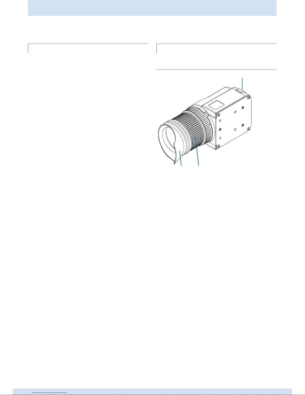
1.2.1 Overview
① Tally lamp
Switches on when a camera's tally signal is being input. For the
lamps on/off settings, see "Tally Settings" in "3.3 Settings Menu
List".
② Visibility adjustment ring
Adjusts the image to the photographer's visibility. For details, see
"2.2.2 Adjusting the visibility".
③ Eye cup
Blocks out exterior light.
①
③ ②
Page 7
Chapter 1 About the Product
7
1.2 Names and Functions of Parts
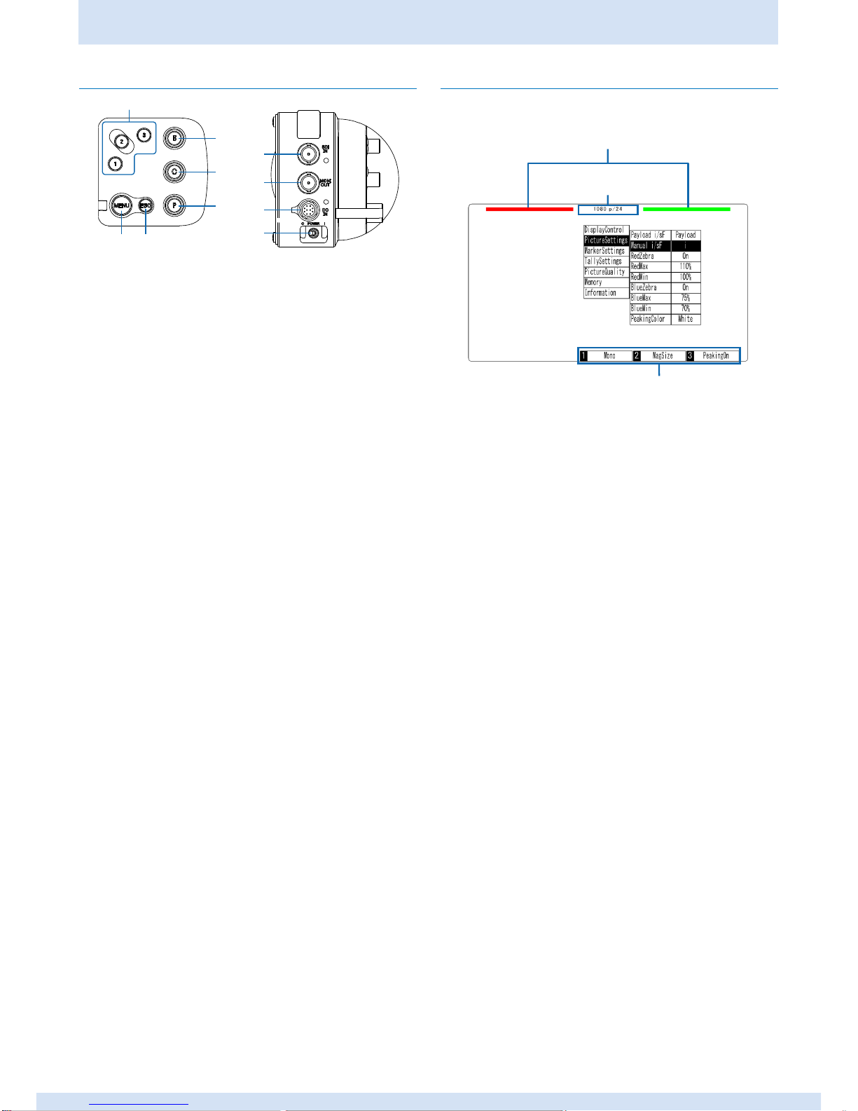
1.2.2 Operation section
① MENU encoder
Displays the menu screen and used to make menu settings. For
details, see "3.2 Basic Operations on the Menu Screen".
② Buttons [1] to [3]
Performs the menu function assigned to each button. For details,
see "4.1 Assigning Menu Items to Buttons [1] to [3] for the Function
Section".
③ ESC button
Closes the menu screen and used to make menu settings.
④ Volume for brightness adjustment
Adjusts the brightness of the displayed image. For details, see
"2.2.2 Adjusting the screen".
⑤ Volume for contrast adjustment
Adjusts the contrast of the displayed image. For details, see "2.2.2
Adjusting the screen".
⑥ Volume for peaking adjustment
Adjusts the peaking strength. For details, see "2.2.2 Adjusting the
screen".
⑦ SDI IN (connector input) terminal
Connects the cable for a camera (for image signal input).
For details on the connection method, see "2.1 Attaching to a
Camera".
⑧ MONI OUT (monitor output) terminal
Connects the cable for a monitor.
⑨ DC IN (DC power input) terminal
Connects the cable for the DC power supply.
Connects the tally signal (R, G).
⑩ POWER switch
Switches the product on or off.
1.2.3 Display
The following menu screen and indicators appear on the display.
For details on changing the menu screen display and settings, see
"Chapter 3 Changing the Screen Display and Settings".
① Box tally display
When the Tally Display in Tally Settings is set to ON, and the tally R
signal is GND, a red box tally is displayed on the left.
When the Tally Display in Tally Settings is set to ON, and the tally G
signal is GND, a green box tally is displayed on the right.
② Display input signal format
Displays the format of the signal being input. "NO SIGNAL" is
displayed when no video signal is being input. For details, see
"5.2 Error List".
③ Display assigned menu
Displays the menu assigned to buttons [1] to [3]. For details, see
"4.1 Assigning Menu Items to Buttons [1] to [3] for the Function
Section".
②
① ③
⑥
⑤
④
⑨
⑧
⑦
⑩
③
②
①
Page 8

Chapter 2 Preparations and Basic Operations
2.1 Attaching to a Camera/
2.2 Adjusting the Screen
8
Chapter 2 Preparations and Basic
Operations
This chapter explains how to attach this product to a camera and make
adjustments.
2.1 Attaching to a Camera
1 Attach this product to a camera.
For details on attaching, see the documentation supplied with the
camera you are using.
2 Connect the camera to this product with the BNC cable.
Connect the supplied camera connection cable.
• Removing
Disconnect the cables.
2.2 Adjusting the Screen
2.2.1 Adjusting the screen
Adjust the screen brightness, contrast, and peaking using the
adjustment volumes of the operation section.
Volume for brightness adjustment
Turn the knob left or right to adjust the brightness of the displayed
image.
• Adjustment results do not affect the camera's output signal.
Volume for contrast adjustment
Turn the knob left or right to adjust the contrast of the displayed image.
• Adjustment results do not affect the camera's output signal.
Volume for peaking adjustment
Turn the knob left or right to adjust the peaking strength in the image.
• To adjust peaking, you need to turn on Peaking On in Display
Control from the menu beforehand.
MEMO
MEMO
MEMO
BNC cable
(for image signal input)
Supplied camera connection cable
Page 9

Chapter 2 Preparations and Basic Operations
9
2.2 Adjusting the Screen
2.2.2 Adjusting the Visibility
Rotate the visibility adjustment ring to find the optimum image display.
The eyepiece moves in and out as you rotate the ring.
Visibility
adjustment ring
Page 10

Chapter 3 Changing the Screen Display and Settings
3.1 Displaying the Menu Screen/
3.2 Basic Operations on the Menu Screen
10
Chapter 3 Changing the Screen Display and Settings
This chapter explains how to change the screen display and settings. Make settings from the menu screen.
3.1 Displaying the Menu Screen
1 Press MENU encoder of the operation section.
The menu screen is displayed.
•To close the menu screen
1 Press the ESC button.
3.2 Basic Operations on the Menu
Screen
This section describes the basic operations for the menu screen.
1 Display the menu screen.
2 Turn the MENU encoder left or right, and then select the menu item
you want to set.
3 Press the MENU encoder to confirm the setting.
Page 11

Chapter 3 Changing the Screen Display and Settings
11
3.3 Settings Menu List
3.3 Settings Menu List
This section shows the functions that can be configured from the menu screen.
Display Control
Sets the display method except for image display information.
The setting items are as follows.
Setting item 1
Setting item 2
Content (initial value: underlined)
Format
Off, On
Off: Does not display format information for the input signal.
Displays format information
for the input signal.
On: Displays format information for the input signal.
Camera Info.
Off, On
Off: Does not display supplemental output information.
Displays supplemental information
output from the camera.
(*For future use)
On: Displays supplemental output information.
Marker On
Off, On
Off: Does not display any markers.
Switches between showing and
hiding the markers.
On: Displays all the markers.
Flip Screen
Off, On
Off: Does not flip the input image.
Switches between flipping and not
flipping the input image.
On: Flips the input image.
Zebra
Off, On
Off: Does not display a zebra pattern on the input image.
Switches between showing and not
showing the zebra pattern on the
input image.
On: Displays a zebra pattern on the input image.
Mono
Off, On
Off: Displays the input image in color.
Switches between displaying and
not displaying the input image in
monochrome.
On: Displays the input image in monochrome.
Blue Only
Off, On
Off: Displays the input image in color.
Switches between displaying and
not displaying only the blue
components in the input image.
On: Displays only the blue components in the input image.
Peaking On
Off, On
Off: Does not display peaking.
Switches between showing and
hiding peaking.
On: Displays peaking.
Mag Size(*)
Off, x2, x4
Off: Does not magnify the displayed image.
Magnifies the displayed image.
x2: Magnifies the displayed image by two.
x4: Magnifies the displayed image by four.
Mag Position(*)
Center, L-Top, R-Top, L-Bot,
Center: Magnifies the image at the center of the display.
Sets the display position for the
R-Bot
L-Top: Magnifies the image at the top-left of the display.
magnified image.
R-Top: Magnifies the image at the top-right of the display.
L-Bot: Magnifies the image at the bottom-left of the display.
R-Bot: Magnifies the image at the bottom-right of the
display.
(*)
Magnifies the input image by 2 or 4 times.
You can also set the display position for the magnified image.
Continued on next page
4 times
2 times
Page 12

Chapter 3 Changing the Screen Display and Settings
3.3 Settings Menu List
12
From previous page
Picture Settings
Configures settings for image displays on this product.
The setting items are as follows.
Setting item
Setting item 2
Content (initial value: underlined)
Payload i/sF
Payload, Manual
Payload: Set automatically.
Sets automatic or manual for the
input signal display method.
Manual: Set manually.
Manual i/sF
i, sF
i: Displays using the interlace method.
Sets the input image display
method during manual
configuration.
sF: Displays using the segment frame method.
Red Zebra
Off, On
Off: Does not display a red zebra pattern.
Switches between showing and not
showing the red zebra pattern.
(Only available when Zebra is set to
On)
On: Displays a red zebra pattern.
Red Max
110% to -7%
Sets the maximum red zebra
pattern display level.
Red Min
109% to 100% to -8%
Sets the minimum red zebra pattern
display level.
Blue Zebra
Off, On
Off: Does not display a blue zebra pattern.
Switches between showing and not
showing the blue zebra pattern.
(Only available when Zebra is set to
On)
On: Displays a blue zebra pattern.
Blue Max
110% to 75% to -7%
Sets the maximum blue zebra
pattern display level.
Blue Min
109% to 70% to -8%
Sets the minimum blue zebra
pattern display level.
Peaking Color
White, Red, Yellow
White: Displays the peaking in white.
Switches the peaking display color.
Red: Displays the peaking in red.
Yellow: Displays the peaking in yellow.
Continued on next page
Page 13

Chapter 3 Changing the Screen Display and Settings
13
3.3 Settings Menu List
From previous page
Marker Settings
Configures the display settings for the product's markers.
The setting items are as follows.
Setting item
Setting item 2
Content (initial value: underlined)
Marker Color
White, Red, Yellow,
White: Displays the markers in white.
Sets the marker display color.
Black
Red: Displays the markers in red.
Yellow: Displays the markers in yellow.
Black: Displays the markers in black.
Center
Off, On
Off: Does not display the center marker.
Switches between showing and
hiding the center marker. (Only
available when Marker On is set to
On)
On: Displays the center marker.
Frame
Off, On
Off: Does not display the frame marker.
Switches between showing and
hiding the frame marker. (Only
available when Marker On is set to
On)
On: Displays the frame marker.
1.33:1
Off, On
Off: Does not display the 1.33:1 aspect ratio guide marker.
Switches between showing and
hiding the 1.33:1 aspect ratio guide
marker. (Only available when Marker
On is set to On)
On: Displays the 1.33:1 aspect ratio guide marker.
1.88:1
Off, On
Off: Does not display the 1.88:1 aspect ratio guide marker.
Switches between showing and
hiding the 1.88:1 aspect ratio guide
marker. (Only available when Marker
On is set to On)
On: Displays the 1.88:1 aspect ratio guide marker.
2.35:1
Off, On
Off: Does not display the 2.35:1 aspect ratio guide marker.
Switches between showing and
hiding the 2.35:1 aspect ratio guide
marker. (Only available when Marker
On is set to On)
On: Displays the 2.35:1 aspect ratio guide marker.
2.39:1
Off, On
Off: Does not display the 2.39:1 aspect ratio guide marker.
Switches between showing and
hiding the 2.39:1 aspect ratio guide
marker. (Only available when Marker
On is set to On)
On: Displays the 2.39:1 aspect ratio guide marker.
1.85:1
Off, On
Off: Does not display the 1.85:1 aspect ratio guide marker.
Switches between showing and
hiding the 1.85:1 aspect ratio guide
marker. (Only available when Marker
On is set to On)
On: Displays the 1.85:1 aspect ratio guide marker.
Marker Mask
Off, On
Off: Does not use a mask.
Switches between using and not
using a mask for the areas outside
the marker display range. (Only
available when Marker On is set to
On)
On: Uses a mask.
Continued on next page
Page 14

Chapter 3 Changing the Screen Display and Settings
3.3 Settings Menu List
14
From previous page
Tally Settings
Sets the tally lamp.
The setting items are as follows.
Setting item
Setting item 2
Content (initial value: underlined)
Tally Select
Ancillary, Signal
Ancillary: Inputs using Ancillary.
Selects the tally input signal
method.
(*For future use)
Signal: Inputs using Signal.
Tally LED
Off, On
Off: Turns off the tally lamp.
Switches between turning on and
turning off the tally lamp.
On: Turns on the tally lamp.
Tally Display
Off, On
Off: Turns off the BOX tally.
Switches between showing and
hiding the BOX tally in the display
screen.
On: Turns on the BOX tally.
Picture Quality
Sets the picture quality for this product.
The setting items are as follows.
Setting item
Content (initial value: underlined)
Luminance
1 to 3 to 5
Sets the display luminance for the OLED
display.
Temperature
5500K, 6500K, 9300K
Sets the color temperature.
Offset G
-50% to 0% to 50%
Adjusts the luminance. (G components)
Offset B
-50% to 0% to 50%
Adjusts the luminance. (B components)
Offset R
-50% to 0% to 50%
Adjusts the luminance. (R components)
Gain G
0% to 100% to 200%
Adjusts the contrast. (G components)
Gain B
0% to 100% to 200%
Adjusts the contrast. (B components)
Gain R
0% to 100% to 200%
Adjusts the contrast. (R components)
Gamma G
1.60 to 2.20 to 2.80
Sets the gamma. (G components)
Gamma B
1.60 to 2.20 to 2.80
Sets the gamma. (B components)
Gamma R
1.60 to 2.20 to 2.80
Sets the gamma. (R components)
Black Insertion
0%, 10%, 20%, 30%
Sets the ratio of black insertion applied to
the display image.
Continued on next page
Page 15

Chapter 3 Changing the Screen Display and Settings
15
3.3 Settings Menu List
From previous page
Memory
This function allows you to store up to six menu settings, and then load them when needed.
The setting items are as follows.
Setting item
Setting item 2
Content (initial value: underlined)
Load
User1 to User6
Loads the settings registered to that number.
Save
User1 to User6
Select the number to which you want to save the settings.
Delete
User1 to User6
Select the number from which you want to delete the settings.
Boot Select
User1 to User6,
Last Memory
Select the settings loaded when power-up.
Information
Checks the version of this product.
The setting items are as follows.
Setting item
Content (initial value: underlined)
FPGA Ver.
Displays the hardware version.
Firmware Ver.
Displays the software version.
Factory Default
Returns all menu settings to default settings (factory settings).
• When settings have been returned to default settings, they cannot be restored.
Page 16

Chapter 4 Useful Functions
4.1 Assigning Menu Items to Buttons [1] to [3] for the Operation
Section/4.2 Removing and Installing the Eyepiece
16
Chapter 4 Useful Functions
4.1 Assigning Menu Items to Buttons
[1] to [3] for the Operation Section
You can assign functions to buttons [1] to [3] on the menu screen in the
operation section panel.
1 Configure the settings on the menu screen.
2 Press and hold down the button to which you want to assign the
function on the menu screen for at least three seconds.
• The following functions cannot be assigned.
‒ Picture Settings
Red Max
Red Min
Blue Max
Blue Min
‒ Picture Quality
Luminance
Offset (G, B, R)
Gain (G, B, R)
Gamma (G, B, R)
‒ Memory
Load
Save
Delete
Boot Select
‒ Information
FPGA Ver.
Firmware Ver.
Factory Default
4.2 Removing and Installing the
Eyepiece
The following section explains how to remove and attach the
eyepiece.
Removing the eyepiece
1 Press the lock switch on the product, and rotate the eyepiece in the
direction indicated by the arrow.
2 Align the red mark on the side of the product with the ▲ mark on the
eyepiece, and then carefully pull out the eyepiece.
When rotating the eyepiece, make sure you rotate the large section with
the ▲ mark.
Reattaching the eyepiece
1 Align the red mark on the side of the product with the ▲ mark on the
eyepiece.
2 Rotate the eyepiece in the opposite direction to the arrow shown in
step 1 from "Removing the eyepiece".
3 Rotate the eyepiece until the lock switch clicks.
MEMO
MEMO
Lock switch
▲ mark
Page 17

Chapter 5 Troubleshooting
17
5.1 When the Product is Not Operating Normally / 5.2 Error List /
5.3 If the Unit Malfunctions or Trouble Occurs
/////////////
Chapter 5 Troubleshooting
This chapter describes troubleshooting methods to use when the product is not operating normally.
5.1 When the Product is Not
Operating Normally
When the product is not operating normally, refer to the following chart,
and then carry out the appropriate solution.
If the problem is not resolved, contact your local dealer or an
Astrodesign sales representative.
Problem
Check point
Solution
No images
are
displayed.
1) Is the camera
operating?
2) Is the camera
cable connected
correctly?
1) Check that the camera is
operating normally.
2) Check that the camera cable is
connected correctly.
For details on connecting to this
product, see "2.1 Attaching to a
Camera". For details on connecting
to the camera, see the
documentation provided with the
camera.
• Due to the nature of OLEDs, the following effects may occur, but they
are not malfunctions.
‒ Changes in response time, brightness, and color due to the
surrounding temperature
‒ Brightness irregularities, vertical lines, and minute spots can be
seen
‒ Optical characteristics (brightness, display irregularities, etc.)
change depending on the operation time (particularly in low
temperature environments)
‒ Changes in display color depending on the viewing angle can be
seen
‒ Afterimages occur if static patterns are displayed for a long time
5.2 Error List
Error Message
Content
Solution
NO SIGNAL
No display
image signal
is being input.
1) Check that the camera is
operating normally.
2) Check that the camera cable is
connected correctly.
For details on connecting to this
product, see "2.1 Attaching to a
Camera". For details on
connecting to the camera, see the
documentation provided with the
camera.
5.3 If the Unit Malfunctions or Trouble
Occurs
Stop using the product, and contact your local dealer or an Astrodesign
sales representative.
Damaged OLED displays will be repaired or exchanged for a fee, even
during the warranty period.
MEMO
Page 18

Chapter 6 Product Specifications
6.1 DC-IN (DC power input) terminal
18
Chapter 6 Product Specifications
This chapter explains the product specifications.
6.1 DC-IN (DC power input) terminal
DC IN terminal pin arrangement
Pin numbers and names, function list
Pin number
Name
Function
1
GND
Grand terminal
2
TALLY R
Tally input terminal (red)
3
TALLY G
Tally input terminal (green)
4
DC IN
Power supply terminal (DC 9-32V)
* Make sure the cable resistance is 50 or less.
Tally signal
Tally controller
Switch
Cable resistance
Control IC
Low level threshold: 0.8 V
Tally receiving circuit
Page 19

Chapter 6 Product Specifications
19
6.2 Input Format / 6.3 Input Signals
6.2 Input Format
Format
Frame Rate
(Hz)
Active Line
Per Frame
Total Line
Per Frame
Line
Frequency
(kHz)
Samples
Per Active
Line
Samples Per
Total Line
Scanning
*1
*2
1080i/60
1080i/59.94
1080sF/29.97
30/1.001
1080
1125
33.72
1920
2200
i
sF
①
1080i/60
1080sF/30
30
1080
1125
33.75
1920
2200
i
sF
1080p/30
1080p/29.97
30/1.001
1080
1125
33.72
1920
2200
p ① 1080p/30
30
1080
1125
33.75
1920
2200
p
1080sF/25
(1080i/50)
1080sF/25
1080i/50
25
1080
1125
28.13
1920
2640
sF
i
①
1080p/25
1080p/25
25
1080
1125
28.13
1920
2640
p
①
1080sF/24
1080sF/23.98
24/1.001
1080
1125
26.97
1920
2750
sF
①
1080sF/24
24
1080
1125
27.00
1920
2750
sF
1080p/24
1080p/23.98
24/1.001
1080
1125
26.97
1920
2750
p ① 1080p/24
24
1080
1125
27.00
1920
2750
p
720p/60
720p/59.94
60/1.001
720
750
44.96
1280
1650
p ② 720p/60
60
720
750
45.00
1280
1650
p
720p/50
720p/50
50
720
750
36.00
1280
1980
p
②
720p/30
720p/29.97
30/1.001
720
750
22.48
1280
3300
p ② 720p/30
30
720
750
22.50
1280
3300
p
720p/25
720p/25
25
720
750
18.75
1280
3960
p
②
720p/24
720p/23.98
24/1.001
720
750
17.98
1280
4125
p ② 720p/24
24
720
750
18.00
1280
4125
p
*1 Scanning skip signal
i = Interlace
sF = Segmented Frame
p = Progressive
* 2 Standard
① Conforms to SMPTE 274 ② Conforms to SMPTE 296
6.3 Input Signals
SDI input specification
Specification
HD-SDI input
・ Conforms to SMPTE 292
・ Field frequency: Auto tracking of 60.00/59.94[Hz] etc as well as auto tracking of the input format are available
Page 20

Chapter 6 Product Specifications
6.4 Display Method / 6.5 General Specification
20
6.4 Display Method
Item
Specification
Display color
8 bit
Contrast ratio
1000:1 or higher
Brightness
88cd/m2
Resolution
1920 (H) x 1200 (V) Pixels
Frame rate
60 Hz
6.5 General Specifications
Item
Specification
Operating temperature
range
0 to 40℃
Storage temperature
range
-10 to 60℃
Operating humidity range
20 to 80% RH (ambient temperature 0 to 40℃ without condensation)
Storage humidity range
10 to 90% RH (ambient temperature 0 to 40℃ without condensation)
Rated voltage
DC 9-32V
Power consumption (main
unit)
6W (TYP)
External dimensions
77 x 85.5 x 214 mm
Weight
0.8 kg
Page 21

Chapter 6 Product Specifications
21
6.6 External Diagram
6.6 External Diagram
Page 22

DF-3512-A Instruction Manual Ver. 1.04
An incorrectly collated manual or a manual with missing pages will be replaced.
All copyrights pertaining to this product are the property of Astrodesign.
This manual shall not be copied in whole or in part without written permission.
The contents of this manual are subject to change without prior notice due to improvements.
The manufacturer shall not be liable for any effects caused by incorrect operation.
All inquiries concerning this product should be addressed to your dealer or to the manufacturer at
the contact numbers given below.
The products and product names mentioned in this manual are the trademarks and registered
trademarks of the companies concerned.
D0437C 2014.6
 Loading...