

Page 1
ASTRO
CDM-700 Series
(Covers Domestic 115V & European 220V Models)
Conveyor Stacker
USER’S GUIDE/PARTS CATALOG
Page 2

This manual is intended solely for the use and information of Astro Machine Corp., its designated agents,
customers, and their employees. The information in this guide was obtained from several different
sources that are deemed reliable by all industry standards. To the best of our knowledge, that information
is accurate in all respects. However, neither Astro Machine Corp. nor any of its agents or employees shall
be responsible for any inaccuracies contained herein.
All rights reserved. No part of this book may be reproduced or transmitted in any form or by any means, electronic or mechanical, including
photocopying, recording, or any information storage and retrieval system, without permission in writing from the publisher.
Page 3

Power Requirements:
Optional Availability:
115 VAC, 60 Hz, 9.0 AMP
220 VAC, 50/60 Hz, 0.5 AMP
Motor Circuit Breaker:
Fuse:
1 AMP
0.5 AMP
Speed Of Tapes:
0" - 250 feet per minute (variable)
Dimensions:
Width: 15" (38.1 cm)
L
ength: 34.5" (87.6 cm)
Height:
Table Top
Weight: 33 lbs. (15 kg)
WARNING!
ONLY CONNECT CONVEYOR TO A PROPERLY GROUNDED OUTLET!
INTRODUCTION
The CDM-700 Conveyor transports media from the Printer and stacks it. As the first piece of
stock exits the Printer, the motor-driven Conveyor Tapes under the Stacker Wheels move it. The
next piece of stock exits the Printer, overlaps the preceding piece, and is moved along the
Conveyor. After clearing the Stacker Wheels, the stock can be unloaded by hand without having
to stop the Printer.
SPECIFICATIONS*
* MANUFACTURER RESERVES THE RIGHT TO CHANGE
SPECIFICATIONS WITHOUT WRITTEN NOTICE.
SAFETY PRECAUTIONS
THIS EQUIPMENT PRESENTS NO PROBLEM WHEN USED PROPERLY.
OBSERVE SAFETY MEASURES WHEN OPERATING THE CONVEYOR:
READ THIS MANUAL CAREFULLY AND FOLLOW RECOMMENDED PROCEDURES.
¾ KEEP HANDS, HAIR, AND CLOTHING CLEAR OF ROLLERS, TAPES, AND
OTHER MOVING PARTS.
¾ ALWAYS TURN CONVEYOR OFF BEFORE ADJUSTING OR CLEANING.
¾ DISCONNECT POWER CORD WHEN MAKING ANY ADJUSTMENTS OR
PERFORMING ANY MAINTENANCE NOT COVERED IN THIS MANUAL.
FAILURE TO DO SO CREATES RISK OF ELECTRICAL SHOCK!
Page 4

USER GUIDE
CAUTION
CONVEYOR IS DESIGNED TO BE PLUGGED
FOR YOUR SAFETY, DO NOT REMOVE
GROUND PIN FROM LINE CORD.
Assembling Conveyor
1. Unpack Conveyor. Do not discard carton until
Conveyor is assembled.
2. Attach Receiving Tray to Conveyor with two
screws provided.
Positioning Conveyor
1. Place Conveyor on the same sturdy table or
workbench next to the Printer as shown.
2. Center Conveyor relative to Printer’s exit.
Operating Conveyor
Plug Conveyor into a properly grounded wall outlet
using power cord supplied.
INTO A GROUNDED OUTLET.
-1-
Page 5
USER GUIDE
WARNING!
DISCONNECT POWER CORD WHEN CHECKING OR REPLACING FUSE!
FAILURE TO DO SO MAY DAMAGE ELECTRONIC CIRCUIT BOARD.
1. Turn Conveyor and Printer ON.
2. Feed stock through Printer and observe the way it is
received by the Conveyor.
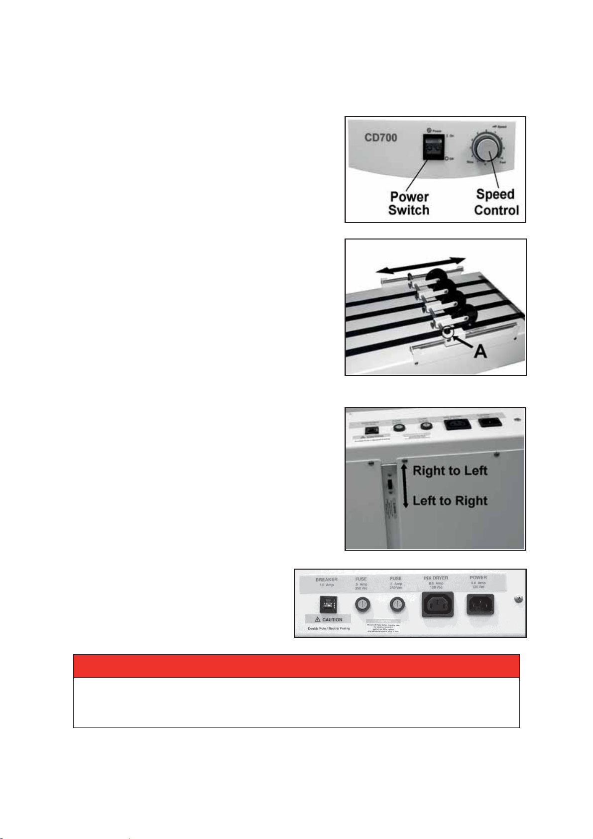
3. Loosen Locking Knob [A] and adjust Stacker
Wheels so lead edge of media just touches Stacking
Rollers as it exits the Printer.
4. Adjust Speed Control to set the amount of overlap
between the pieces. (For less overlap turn Speed
Control clockwise, for more overlap turn Speed
Control counterclockwise.)
Reverse Operation
Conveyor is designed to run from right to left. It can also
operate from left to right. To switch operation direction,
first move Guide Roller Assembly and Stacking Tray to
opposite sides of the Conveyor. Then switch the
Reversing Switch (located under Conveyor) to the
reverse operating position.
Troubleshooting
If Conveyor fails to run, check for jammed
paper between Tapes and Roller. Also, check
Fuse and Motor Circuit Breaker and replace
or reset if necessary. Fuse Holders and Circuit
Breaker located on rear of Conveyor.
ALWAYS REPLACE FUSE WITH THE SAME TYPE.
-2-
Page 6
USER GUIDE
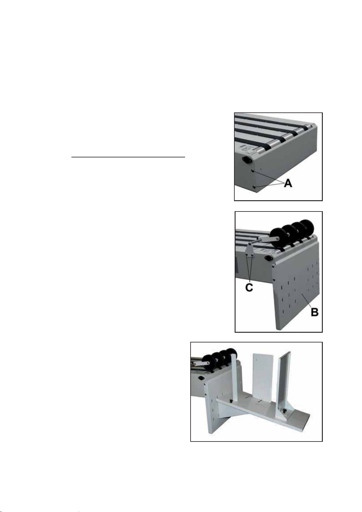
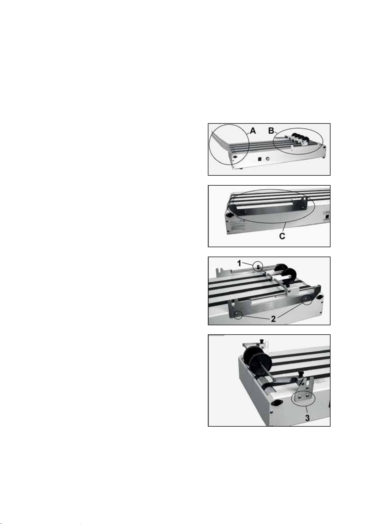
Optional DTM-255/DTM-250 Conveyor Drop Tray Installation
DTM-255 Drop Tray is for Left-to-Right Operation. DTM-250 Drop Tray is for Right-toLeft Operation. Assemble and install Conveyor Drop Tray on exit end of Conveyor:
1. Remove two screws attaching Stacking Tray to
Conveyor and remove Tray.
2. Remove four screws [A] that mount Front Cover
Plate to Conveyor.
DO NOT remove Front Cover Plate.
3. While holding Front Cover Plate in place, install
Drop Tray Support Bracket [B] using four screws
removed in Step 2.
4. Install Media Guide Roller Assembly using four
screws supplied [C]. Mount Media Guide Roller
Assembly as shown with Rollers resting on Exit
Roller of Conveyor.
5. Install Tray Base on Drop Tray
Support Bracket.
Tray adjusts up and down to allow
stacking more or less media.
6. Remove knobs from Guides.
Assemble Guides to Tray Base as
shown. Largest Guide is the Rear Stop
Guide. Second largest Guide is
installed on non-operator's side of
Conveyor and smallest Guide is
installed on operator's side as shown.
-3-
Page 7
USER GUIDE
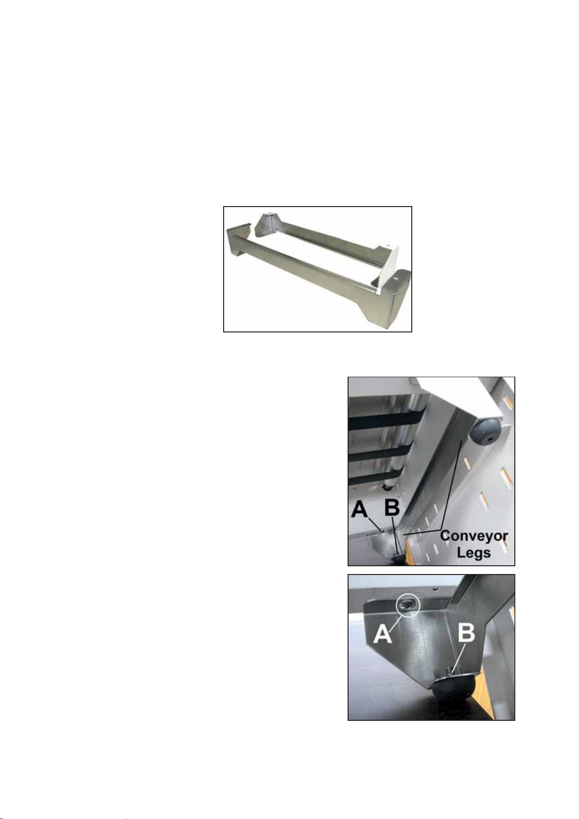
Optional 57E-600-10 Conveyor Leg Kit Installation
(for Use with M-Series Printers)
Install Conveyor Legs on the Conveyor to allow proper alignment with M-Series Printers.
CONTENTS OF KIT:
1. Conveyor Legs (2)
2. Screws (4)
INSTALL CONVEYOR LEGS:
1. Remove (4) Rubber Feet from bottom of Conveyor.
2. Attach Conveyor Legs across the bottom front and
rear of Conveyor using Rubber Foot holes [A] and
four screws included with Kit.
3. Reattach Rubber Feet to Conveyor Legs using
predrilled holes [B] provided.
-4-
Page 8
USER GUIDE
Optional DK-700 Dryer Kit
Dryer Kit Includes: Front Exit Roller Assembly, Guide Roller Support, Front Roller
Support, Rear Roller Support, 2 Dryer Support Shafts, 8 mounting screws
1. Before installing DK-700 Dryer Kit, remove
these parts from the CDM-700 Conveyor.
A. Stacking Tray [A] (2 screws).
B. Guide Assembly [B] (4 screws).
Remove Operator’s Side Bracket first,
then the Rear Support Bracket.
2. Install new Rear Roller Support [C] using
two screws (as shown).
3. Hook Guide Roller Support over the shaft on
Rear Roller Support [1]. Install Front Roller
Support using two screws [2] (as shown).
4. Install Front Exit Roller Assembly by
attaching mounting brackets to Conveyor
Frame (as shown) using two screws on
each side [3].
-5-
Page 9

USER GUIDE
CAUTION
DO NOT OPERATE DRYER IF BELTS ON CONVEYOR ARE NOT TURNING.
DO NOT BLOCK CONVEYOR EXIT WHEN USING DRYER.
5. Remove two Levers [4] and Bearing Washers
[5] from two Dryer Support Shafts [6]. Install
two Shaft Assemblies into holes provided in
Dryer (as shown). Reinstall Levers [4] and
Bearing Washers [5] on Shafts.
NOTE: When installing the two Levers [4],
make sure the cams on the opposite end of the
shaft are in the same position as the cams on
the Levers.
6. Dryer Assembly can now be placed in Support Brackets.
Make sure Bearing Washers are between the Support
Brackets and the cams (as shown).
NOTE: Bearing Washers should go between Support
Brackets and cams.
7. Plug cord supplied with Dryer into Dryer
receptacle, then into receptacle labeled "Dryer"
on the Conveyor. Then plug the Conveyor into
the wall outlet.
8. To operate the Dryer, set the two Levers so
media can pass under the Dryer without
interference. Then turn Dryer power switch ON.
Turn Conveyor ON.
Dryer and Guide Rollers can be adjusted from
side to side (by sliding them on Shaft
Assemblies) to accommodate varying media
sizes and print positioning.
NOTE: Dryer will not operate if Conveyor is not
turned ON.
-6-
Page 10

USER GUIDE
-7-
Page 11

PARTS CATALOG
GROUP 1 – Mechanical
9
GROUP 2 – Electrical
11
GROUP 2A – Motor Drive
13
GROUP 3 – Labels
14
GROUP 4 – Wheel Guide and Bracket Assembly
15
GROUP 5 – DT-255 Drop Tray (R-L) (Optional)
16
GROUP 5A – Rear Wheel Guide & Bracket Assembly
17
GROUP 6 – DK-700 Dryer Kit Parts (Optional)
18
PARTS INDEX
20
Parts Table of Contents
NOTE: When you see a Key number repeated in a listing,
check the voltage of your particular model:
x Voltage: 115V or 220V
-8-
Page 12

PARTS CATALOG
GROUP 1
MECHANICAL
-9-
Page 13

PARTS CATALOG
KEY
PART NO.
DESCRIPTION
QTY.
1.
57-150-08
END CAP, BODY CLOSURE
2
2.
57-100-15
DRIVE ROLLER ASSEMBLY
1
3.
123-0309
BELT, CONVEYOR DELIVERY
4
4.
123-0771
BELT, 120XL037 NEOPRENE CLASS
1
5.
123-1136
SCREW, 8-32 x 1/4 PH TRUSS HD
22
6.
57P-600-02
CONVEYOR BODY WELDMENT (115V)
1
6.
57P-610-02
CONVEYOR BODY WELDMENT (220V)
1
7.
123-0620
FOOT, #7OASHORA
4
8.
57-100-84
MOTOR ASSEMBLY
1
9.
57-150-42
MOTOR BASE
1
10.
123-0100
WASHER, 1/2 x 0.218 x 0.048 THK
4
11.
123-0237
STAR-WASHER, #10 EXTERNAL
4
12.
123-0024
SCREW, 10-32 x 3/8 PH TRUSS HD. MS ZINC
4
13.
123-1135
SCREW, 6-32 x 1/4 PH TRUSS HD.
15
14.
123-0425
NUT, HEX 4-40
2
15.
123-1105
SWITCH, S SERIES SLIDE
1
16.
123-1023
SCREW, 4-40 x 5/16 RH PH
2
17.
57-100-50
BRACKET, TRANSFORMER
1
18.
57-150-43
COVER
1
19.
123-1103
SWITCH
1
20.
57-100-17
IDLER ROLLER
3
KEY
PART NO.
DESCRIPTION
QTY.
21.
123-1104
CIRCUIT BREAKER
1
22.
123-0355
FUSE HOLDER
2
23.
57-500-01
AC OUTLET ASSEMBLY
1
24.
57-500-03
AC INLET ASSEMBLY (115V)
1
24.
57-500-21
FILTER, POWER ENTRY MODULE (220V)
1
25.
57-500-02
TRANSFORMER (115V, 60Hz)
1
25.
57-500-16
TRANSFORMER (220V, 50/60Hz)
1
26.
57-500-13
SPEED CONTROL
1
27.
123-0191
WASHER, PLAIN #6
1
28.
123-1106
RELAY
1
29.
123-1101
KNOB, PURE TOUCH
1
30.
90-103-52
BALL BEARING HOUSING ASSEMBLY
8
31.
123-0275
SCREW, 6-32 x 1/4 OVAL PH. HD.
16
32.
57-601-03
WHEEL BRACKET ASSY. (SEE GROUP 4)
1
33.
01
WHEEL GUIDE & BRACKET ASSEMBLY
(SEE GROUP 4)
1
34.
57P-601-16
RECEIVING TRAY
1
35.
123-0635*
POWER CORD (115V)
1
35.
123-0735*
POWER CORD (220V)
1
36.
57-550-25*
DECAL, POWER ENTRY 115V
1
36.
57-550-30*
DECAL, POWER ENTRY 220V
1
*
DROP TRAY KIT, RIGHT-TO-LEFT
(SEE PAGE 3) (SEE GROUP 6)
1
*
DROP TRAY KIT, LEFT-TO-RIGHT
(SEE PAGE 3) (SEE GROUP 6A)
1
*
57E
-10
CONVEYOR LEG KIT FOR USE WITH M-SERIES
PRINTERS
(SEE PAGE 4)
1
*NOT SHOWN
GROUP 1 – MECHANICAL
57-601-
DT-255
DT-250
-600
-10-
Page 14

PARTS CATALOG
GROUP 2 – ELECTRICAL
-11-
Page 15

PARTS CATALOG
KEY
PART NO.
DESCRIPTION
QTY.
1.
57-500-02
TRANSFORMER (115V, 60Hz)
1
1.
57-500-16
TRANSFORMER (220V, 50-60Hz)
1
2.
57-500-03
AC/INLET ASSEMBLY (115V)
1
2.
57-500-21
FILTER, POWER ENTRY MODULE (220V)
1
3.
57-500-01
AC/OUTLET ASSEMBLY
1
4.
123-0680
FUSE, .5A 250V (3AG) #313.500 (115V)
2
4.
123-1179
FUSE, .3A SLOW BLOW, #313.300 (220V)
2
5.
123-0355
FUSE HOLDER
2
6.
123-1104
CIRCUIT BREAKER
1
7.
57-500-04
SWITCH ASSEMBLY
1
8.
57-500-13
SPEED CONTROL ASSEMBLY
1
9.
57-550-20
INDICATOR PLATE
1
10.
123-1101
KNOB, PURE TOUCH
1
11.
123-1103
SWITCH
1
12.
123-1106
RELAY
1
13.
57-100-84
MOTOR ASSEMBLY, 24 V DC
1
14.
57-500-15
WIRE HARNESS, AC/OUTLET
1
15.
57-500-11
WIRE HARNESS, AC/OUTLET
1
16.
57-500-07
WIRE HARNESS, AC/INTLET
1
17.
57-500-10
WIRE HARNESS, FUSE
1
18.
57-500-08
WIRE HARNESS, FUSE
1
19.
57-500-05
WIRE HARNESS, FUSE
1
20.
57-500-17
WIRE HARNESS, TRANSFORMER-SPEED CONTROL
1
21.
57-500-12
WIRE HARNESS, A/C OUTLET
1
22.
57-500-06
WIRE HARNESS, A/C OUTLET
1
23.
57-500-14
WIRE HARNESS, FUSE
1
24.
57-500-09
WIRE HARNESS ASSEMBLY, MOTOR
1
GROUP 2 – ELECTRICAL
-12-
Page 16

PARTS CATALOG
KEY
PART NO.
DESCRIPTION
QTY.
1.
57-100-16
DRIVE ROLLER
1
2.
123-0036
ROLL PIN
1
3.
57-100-80
PULLEY, 12XLO
1
4.
123-0771
BELT, 120XLO31
1
5.
123-0322
SET SCREW, 8-32 x 1/4
1
6.
57-100-78
MOTOR PULLEY, 28 TEETH
1
7.
123-0017
SCREW, 10-32 x 1/4 PH TRUSS HD.
2
8.
CD-301-06
MOTOR BRACKET
1
9.
57-100-85
MOTOR
1
GROUP 2A – MOTOR DRIVE
-13-
Page 17

PARTS CATALOG
KEY
PART NO.
DESCRIPTION
QTY.
1.
57-550-25
DECAL, POWER ENTRY (115V)
1
1.
57-550-30
DECAL, POWER ENTRY (220V)
1
2.
123-1033
LABEL, CAUTION DISCONNECT POWER
1
3.
123-1115
LABEL, CAUTION/ DOUBLE POLE
1
4.
123-1962
DECAL, DATA PLATE GENERIC
1
5.
123-1121
LABEL, CAUTION REVERSE SWITCH
1
6.
123-2597
LABEL, CAUTION EXPOSED ROLLER
2
GROUP 3 – LABELS
-14-
Page 18

PARTS CATALOG
KEY
PART NO.
DESCRIPTION
QTY.
KEY
PART NO.
DESCRIPTION
QTY.
1.
57P-601-11
WHEEL BRACKET
2 9.
95-105-19
MEDIA GUIDE KNOB ASSEMBLY
4
2.
123-0017
SCREW, 10-32 x 1/4 PH TRUSS HD.
3 10.
57-601-13
FORK
4
3.
57-601-10
ROD
2 11
57P-601-05
WHEEL ASSEMBLY
4
4.
57-150-27
BRACKET
1 11.1
57-150-37
WHEEL ARM WELDMENT
4
5.
57-100-19
THUMBSCREW
1
11.2
57-100-30
WHEEL SHAFT
4
6.
57-601-06
WHEEL GUIDE SHAFT
1
11.3
CD-300-21
STACKER WHEEL
4
7.
57-100-28
SHAFT BRACKET
1
11.4
123-0017
SCREW, 10-32 x 1/4 PH TRUSS HD.
8
8.
123-0695
SPRING PIN, 3/32 x 1/2
1
GROUP 4 – WHEEL GUIDE AND BRACKET ASSEMBLY
-15-
Page 19

PARTS CATALOG
KEY
PART NO.
DESCRIPTION
QTY.
1.
123-0068
WASHER, #10 PLAIN, SS 18-8
3
2.
57P-602-04
DROP TRAY BASE
1
3.
57P-602-01
WHEEL GUIDE AND BRACKET ASSEMBLY (SEE GROUP 6B)
1
4.
29-400-16
NUT
2
5.
29-400-28
KNOB ASSEMBLY, 10-32 x 1/2
2
6.
25P-252-09
DROP TRAY PLATFORM
1
7.
25P-252-17
MEDIA GUIDE
1
8.
25P-252-20
SIDE GUIDE ASSEMBLY
1
9.
25P-252-22
STOPPER ASSEMBLY
1
10.
94-104-06
KNOB, METERING BRACKET
1
GROUP 5 – DT-255 LEFT-TO-RIGHT DROP TRAY (OPTIONAL)
-16-
Page 20

PARTS CATALOG
KEY
PART NO.
DESCRIPTION
QTY.
57P-602-01
WHEEL GUIDE AND BRACKET ASSEMBLY
1
1.
123-0017
SCREW, 10-32 x 1/4 PH TRUSS HD.
2
2.
57-602-10
WHEEL ROD
1
3.
57P-602-11
BRACKET
2
4.
57-601-13
FORK
4
5.
95-105-19
MEDIA GUIDE KNOB ASSEMBLY
4
6.
57P-601-05
WHEEL ASSEMBLY
4
6.1
123-0017
SCREW, 10-32 x 1/4 PH TRUSS HD.
8
6.2
57-100-30
WHEEL SHAFT
4
6.3
57-150-37
WHEEL ARM WELDMENT
4
6.4
CD-300-21
STACKER WHEEL
4
GROUP 5A – DT-255 REAR WHEEL GUIDE AND BRACKET
-17-
Page 21

PARTS CATALOG
GROUP 6 – DK-700 DRYER KIT PARTS (OPTIONAL)
-18-
Page 22

PARTS CATALOG
KEY
PART NO.
DESCRIPTION
QTY.
1.
123-0002
SCREW, 10-32 x 3/8 PH UNDERCUT SS
2
2.
123-0017
SCREW, 10-32 x 1/4 PH TRUSS HD.
10
3.
123-1135
SCREW, 6-32 x 1/4 PH TRUSS HD.
2
4.
123-1136
SCREW, 8-32 x 1/4 PH TRUSS HD.
8
5.
123-1986
BEARING CLIP
4
6.
123-1987
O-RING
4
7.
123-2067
SCREW, 6-32 x 5/16 SOC. HD. CAP
2
8.
123-2078
SCREW, 6-32 SOC. HD.
2
9.
20-100-38
SPACER
4
10.
24-101-11
THUMBSCREW, 10-32
2
11.
32-110-48
SPACER
6
12.
57-100-19
THUMBSCREW
1
13.
57-100-25
WHEEL GUIDE SHAFT
1
14.
57-150-27
BRACKET
1
15.
57P-601-05
WHEEL ASSEMBLY
2
15.1
123-0017
SCREW, 10-32 x 1/4 PH TRUSS HD.
4
15.2
57-100-30
WHEEL SHAFT
2
15.3
57-150-37
WHEEL ARM WELDMENT
2
15.4
CD-300-21
STACKER WHEEL
2
KEY
PART NO.
DESCRIPTION
QTY.
16.
57-601-10
WHEEL ROD
2
17.
57-601-13
FORK
4
18.
57-603-08
FRONT WHEEL BRACKET
1
19.
57-603-09
REAR WHEEL BRACKET
1
20.
57-603-12
HEIGHT ADJUSTMENT ARM
2
21.
57-603-13
HEIGHT ADJUSTMENT WHEEL
2
22.
57-603-15
WHEEL ROD
2
23.
57-603-16
STUD
2
24.
57-603-21
EXIT WHEEL ARM
1
25.
57-603-23
EXIT WHEEL BRACKET, L/H
1
26.
57-603-24
EXIT WHEEL BRACKET, R/H
1
27.
57-603-26
WHEEL ROD
1
28.
95-105-19
MEDIA GUIDE KNOB ASSEMBLY
2
29.
CD-300-21
STACKER WHEEL
2
GROUP 6 – DK-700 DRYER KIT PARTS (OPTIONAL)
-19-
Page 23

PARTS INDEX
PART NO.
GROUP
KEY
123-0002
6
1
123-0017
4
2
123-0017
2A
7
123-0017
5A
1
123-0017
5A
6.1
123-0017
6
2
123-0017
6
15.1
123-0024
1
12
123-0036
2A
2
123-0068
5
1
123-0100
1
10
123-0191
1
27
123-0237
1
11
123-0275
1
31
123-0309
1
3
123-0322
2A
5
123-0355
1
22
123-0355
2
5
123-0425
1
14
123-0620
1
7
123-0635
1
35
123-0680
2
4
123-0695
4
8
123-0735
1
35
123-0771
1
4
123-0771
2A
4
123-1023
1
16
123-1033
3
2
123-1081
1
26
123-1101
1
29
123-1101
2
10
123-1103
1
19
123-1103
2
11
123-1104
1
21
123-1104
2
6
123-1105
1
15
123-1106
1
28
123-1106
2
12
123-1115
3
3
123-1117
3
1
123-1121
3
5
123-1135
1
13
123-1135
6
3
123-1136
1
5
123-1136
6
4
123-1179
2
4
123-1962
3
4
123-1986
6
5
PART NO.
GROUP
KEY
123-1987
6
6
123-2067
6
7
123-2078
6
8
123-2597
3
6
20-100-38
6
9
24-101-11
6
10
25P-252-09
5
6
25P-252-17
5
7
25P-252-20
5
8
25P-252-22
5
9
32-110-48
6
11
29-400-16
5
4
29-400-28
5
5
57-100-15
1
2
57-100-16
2A
1
57-100-17
1
20
57-100-19
4
5
57-100-19
6
12
57-100-25
6
13
57-100-28
4
7
57-100-30
4
9.4
57-100-30
5A
6.2
57-100-30
6
15.2
57-100-50
1
17
57-100-78
2A
6
57-100-80
2A
3
57-100-84
1
8
57-100-84
2
13
57-100-85
2A
9
57-150-08
1
1
57-150-27
4
4
57-150-27
6
14
57-150-37
4
9.3
57-150-37
5A
6.3
57-150-37
6
15.3
57-150-42
1
9
57-150-43
1
18
57-500-01
1
23
57-500-01
2
3
57-500-02
1
25
57-500-02
2
1
57-500-03
1
24
57-500-03
2
2
57-500-04
2
7
57-500-05
2
19
57-500-06
2
22
57-500-07
2
16
57-500-08
2
18
PART NO.
GROUP
KEY
57-500-09
2
24
57-500-10
2
17
57-500-11
2
15
57-500-12
2
21
57-500-13
2
8
57-500-14
2
23
57-500-15
2
14
57-500-16
1
25
57-500-16
2
1
57-500-17
2
20
57-500-21
1
24
57-500-21
2
2
57-550-20
2
9
57-550-25
1
36
57-550-25
3
1
57-550-30
1
36
57-550-30
3
1
57-601-01
1
33
57-601-03
1
32
57-601-06
4
6
57-601-10
4
3
57-601-10
6
16
57-601-13
4
9.2
57-601-13
5A
4
57-601-13
6
17
57-602-10
5A
2
57-603-08
6
18
57-603-09
6
19
57-603-12
6
20
57-603-13
6
21
57-603-15
6
22
57-603-16
6
23
57-603-21
6
24
57-603-23
6
25
57-603-24
6
26
57-603-26
6
27
57E-600-10
1
--
57P-600-02
1
6
57P-601-05
4
11
57P-601-05
5A
6
57P-601-05
6
15
57P-601-11
4
1
57P-601-16
1
34
57P-602-01
5
3
57P-602-01
5A
--
57P-602-04
5
2
57P-602-04
5A
2
57P-610-02
1
6
-20-
Page 24

PARTS INDEX
90-103-52
1
30
94-104-06
5
10
95-105-19
4
9.1
95-105-19
5A
5
95-105-19
6
28
CD-300-21
4
9.5
CD-300-21
5A
6.4
CD-300-21
6
15.4
CD-300-21
6
29
CD-301-06
2A
8
DT-250
1
--
DT-255
1
--
DT-255
5
--
-21-
Page 25

Page 26

Copyright © 2017 Astro Machine Corporation
07
/2017
Part Number: 200-CD700 Rev F
Elk Grove Village, Illinois 600
01/16
 Loading...