

Page 1
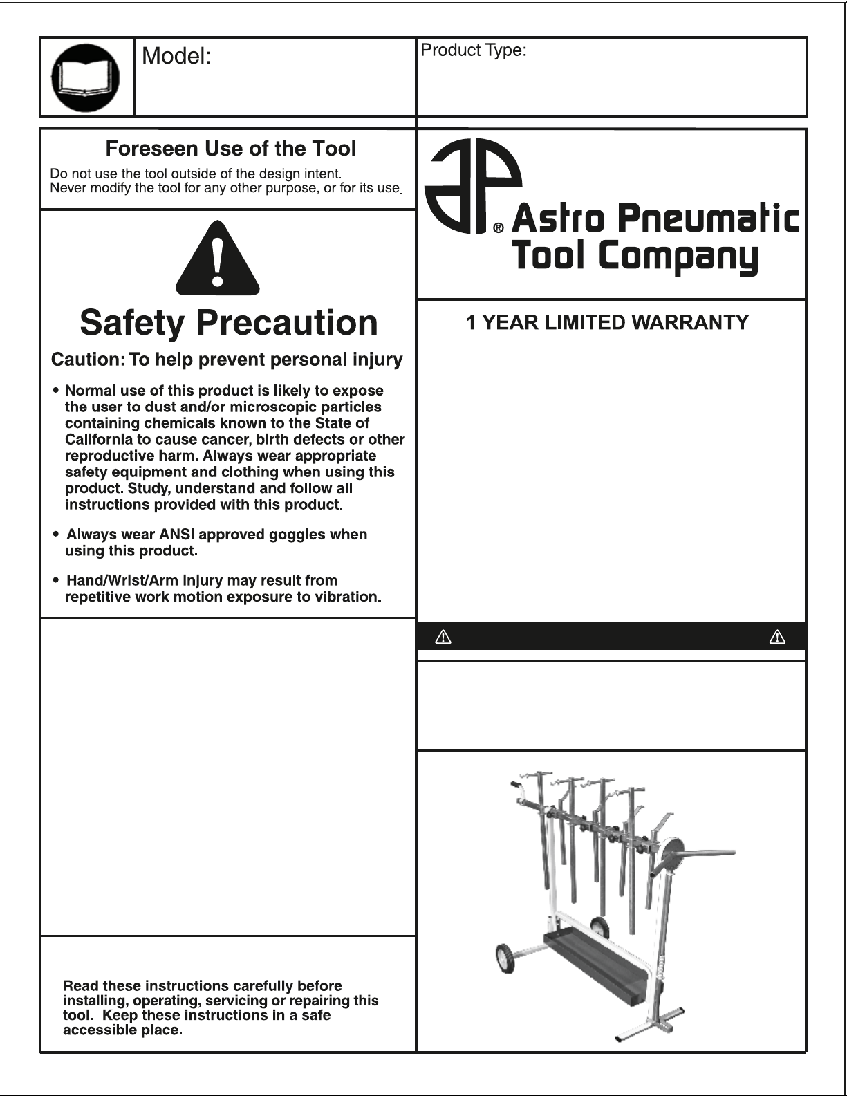
Super Stand
page 1
7300
- Universal Rotating Parts Work Stand
www.astrotools.com
Astro Pneumatic Tool Co. warrants our products to the original user against defective
material or workmanship for a period of 1 year from the date of 1st use. Astro
reserves the right to determine whether the product failed because of defective
material, workmanship or other causes and to charge back for missing parts. Astro
Pneumatic Tool Co., at its discretion, will repair products covered under this warranty
free of charge. The original user is to return the product (with the exceptions listed
below) with the distributor’s name, address, adequate proof of date of purchase or a
copy of warranty card, and a short note explaining the problem. Failures caused by
accident, alteration, or misuse are not covered by this warranty.
Astro Pneumatic Tool Co. or its authorized service representatives must per form all
warrant y repairs. Any repair to the product by unauthorized service representatives
voids this warranty. The rights under this warranty are limited to the original user and
may not be transferred to subsequent owners.
This warranty is in lieu of all other warranties, expressed or implied, including
warranties of merchantability and fitness for a particular purpose. Some states do not
allow the exclusion of limitations of incidental or consequential damages so the above
limitations may not apply to you. All claims must be sent to:
Astro Pneumatic Tool Company
P.O. Box 251935
Los Angeles, CA 90025
Product Information
The Universal Astro Super Stand can
•
handle any panel, fender, door, hood, or
bumper to make repairs and refinishing easy
The Astro Super Stand comes with 8
•
adjustable bars to fit almost any panel
securely
The Astro Super Stands portability allows
•
for fast and easy moving of the part from the
prep. station to the spray booth
The Astro Super Stand's unique design
•
allows for single handed rotation of panels
350 degrees in 16 degree increments
Weight capacity: 200lbs
•
Important
PLEASE DO NOT RETURN ANY PRODUCT TO THE P.O. BOX.
CALL 1-800-221-9705 FOR INSTRUCTIONS.
Unpacking
When unpacking, check the parts diagram and part number
listing on page 3 to make sure all parts are included. If any
parts are missing or damaged, please call your distributor.
Page 2
Super Stand
page 2
7300
- Universal Rotating Parts Work Stand
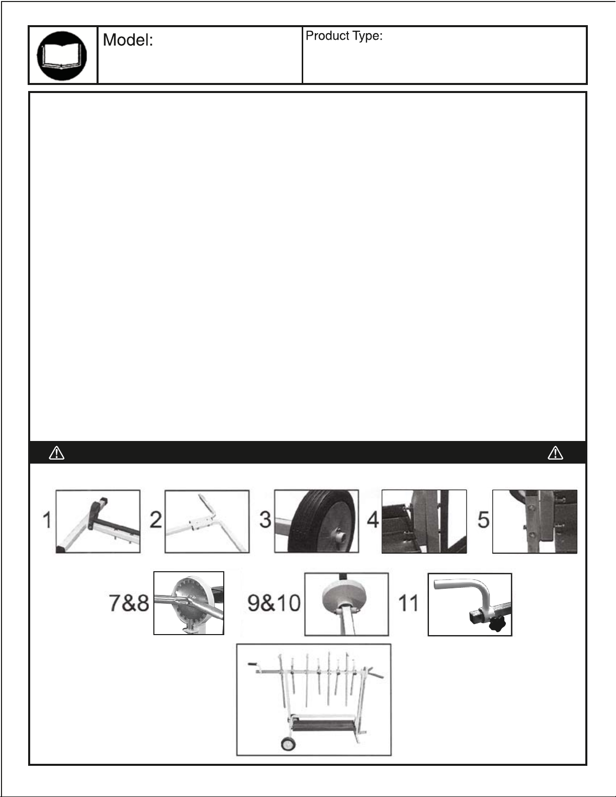
7300 Assembly Instructions
PRIOR TO BEGINNING ASSEMBLY COMPARE PARTS TO PARTS LIST TO ASSURE THAT ALL PARTS ARE INCLUDED.
1) Attach pedal on front brace (#9) with nut (#9E) & bolt (#9D) to the bottom of the front brace.
Completely secure nuts & bolts. Remove temporary bolt at top of front brace and discard.
2) Align the holes on the wheel poles (#12) to the holes of the rear brace (#11). Attach the wheel poles to rear brace
with bolts (#11A), washers (#9C) and nuts (#9B). Completely secure nuts & bolts.
3) Attach wheels (#13) to wheel pole (#12). Position the wheels and large washer (#15) onto the
wheel pole (#12) and secure into place by inserting cotter pin (#14) into predrilled holes in the wheel pole.
Slightly spread ends of cotter pins to assure wheels will not fall off wheel pole.
4) Align the holes on the fixed pole, the holes on the brackets of the tray and the holes on the front brace (#9).
Attach with bolts (#9A), washers (#9C) and nuts (#9B). Do not completely secure.
5) Attach the rear brace (#11) to the fixed pole (#10) and tray (#16) by repeating procedure in step 4.
6) Completely secure nuts & bolts used in steps 4 and 5.
7) Press down pedal and insert the adjustable gear wheel (#5) into the hole at the top of the front brace
(#9) assuring that the predrilled hole on the adjustable gear wheel is facing up.
8) Insert stand pole (#6) onto the adjustable gear wheel (#5).
9) Insert stand pole (#6) through hole of rear brace (#11) and onto stand extension pole (#7).
Secure stand extension pole to stand pole by tightening screw (#7A) on extension.
10) Align the holes of the adjustable gear wheel (#5), stand pole (#6), plastic bushing (#6C), and washer
(#6B) and completely secure with nut (#6D) & bolt (#6A).
11) Handle (#8) to be used for moving stand for storage only.
Do not use to move stand while parts are mounted on stand.
NOTE: When mounting parts onto "Super Stand" select the appropriate suspend arm (#1) or prop arm (#2) for the job.
Do not begin work until you have checked and assured that parts are securely mounted onto "Super Stand"
ALWAYS WEAR ANSI APPROVED SAFETY GLASSES AND CLOTHING WHEN USING THIS UNIT.
Page 3

7300
page 3
Super Stand
- Universal Rotating Parts Work Stand
6B
6D
6C
6A
9B
9C
11A
9C
7A
9C
9C
9C
9B
9A
4
9A, 9B, 9C
9D, 9E
9G
9H
9F
7300-01
7300-02
7300-03
7300-04
7300-05
7300-06
7300-6A
7300-6B
7300-6C
7300-6D
7300-07
Suspend Arm
Prop Arm
Buckle
Knob
Adjustable Gear Wheel
Stand Pole
Stand Bolt
Stand Washer
Plastic Bushing
Stand Nut
Stand Extension Pole
4
4
8
9
1
1
1
2
1
1
1
7300-7A
7300-08
7300-09
7300-9A
7300-9B
7300-9C
7300-9D
7300-9E
7300-9F
7300-9G
7300-9H
Bolt
Handle
Front Brace
3” Bolt
Nut
Washer
Pedal Bolt
Pedal Nut
Pedal
Front Bar
Front Spring
12
1
1
1
4
6
2
2
1
1
1
7300-10
7300-11
7300-11A
7300-12
7300-13
7300-14
7300-15
7300-16
Fixed Pole
Rear Brace
3 1/2” Rear Brace Bolt
Wheel Pole
Wheel
Cotter Pin
Large Washer
Tray
1
1
2
2
2
2
2
1
Page 4

Super Stand
page 4
7300
PART MOUNTING
INSTRUCTIONS FOR
MODEL 7300
Due to the universal nature of this unit and its
capabilities to mount many types of
automobile parts, mounting instructions must
be given in a general manner. When
mounting any part you must first determine
what would be the safest way to secure the
automobile part to the Part Stand.
1)
Begin by examining the specific part that
is being mounted and look for holes on the
partthat will allow the Suspend Arm (part
#1) or Prop Arm (part #2) to be inserted
into.
Hints:
•
Select holes that are as close to the size of
the hook/straight mount for best support.
•
Select holes at the furthest point on the part
being mounted for better support.
•
Suspend Arm and/or Prop Arm can be set
at an angled position for wider range and
support.
•
Suspend Arms and Prop Arms can be used
separately or in conjunction.
•
Suspend Arms have hook on one side and
straight mount on opposite side. Depending
on size of hole selected to mount part,
select which will secure part best.
•
Prop Arms have holes at the end which can
be used to secure part being mounted. If
part being mounted has a lip/tab with hole,
align the hole on the Prop Arm with the hole
on the lip/tab and secure by using a nut &
bolt (not included).
- Universal Rotating Parts Work Stand
MOUNTING SOLUTIONS
BUMPER
DOOR
HOOD
Begin mounting process by deciding length
2)
necessary for Suspend Arm/Prop Arm.
Secure Suspend Arm/Prop Arm into place
by tightening knobs.
Mount part onto Suspend Arm/Prop Arm.
3)
Before proceeding to next step, assure that
part is secure and weight is well distributed
and will not cause stand to tip over.
Next, mount bottom of part to Suspend
4)
Arm/Prop Arm. Follow instructions in step 1.
Assure that part is mounted securely. Test
5)
by slowly rotating part.
FURTHER ASSISTANCE PLEASE
CONTACT YOUR NEAREST DISTRIBUTOR, OR
ASTRO PNEUMATIC TOOL COMPANY AT
IF YOU NEED
(800)221-9705.
CHROME
 Loading...