

Page 1
P126653 01
USC
P./N 126653-01 Rev. E 07/2018
INSTALLATION AND OPERATION
INSTRUCTIONS
Multi-Sided Wood-burning Fireplace
Ce manuel est disponible en francais, simplement
en faire la demande. Numéro de la pièce 126653-02.
PFS
®
MODEL
Windsor STP2
REPORT NO. 09-146
SAVE THIS BOOK
This book is valuable. In addition to instructing you on how to install and maintain your appliance, it also
contains information that will enable you to obtain replacement parts or accessory items when needed. Keep
it with your other important papers.
INSTALLER: Leave this manual with the appliance.
CONSUMER: Retain this manual for future reference.
Installateur : Laissez cette notice avec l’appareil.
Consommateur : Conservez cette notice pour consultation ultérieure.
This Wood-burning fireplace complies with UL127
CAN/ULC-S610-M87 standard as a FACTORY
BUILT FIREPLACE.
Ce foyer au bois est conforme aux UL 127 CAN/ULCS610-M87 norme comme une USINE CONSTRUITE
CHEMINÉE.
This fireplace is approved for use as a Wood-burning fireplace or for use with a vented gas log approved to
ANS Z21.60, Z21.84 standards or for use with a vent-free gas log heater approved to ANS Z21.11.2 standard.
An INNOVATIVE HEARTH PRODUCTS, LLC hood must be installed when using a vent-free log heater (see Accessories, page 18).
FOR CANADA: The authority having jurisdiction
(such as the municipal building department, fire
department, etc.) should be contacted before
installation to determine the need to obtain a permit.
POUR LE CANADA: L’autorité compétente (comme le
service municipal du bâtiment, les pompiers, etc.) doit
être contacté avant l’installation afin de déterminer la
nécessité d’obtenir un permis.
This installation manual will enable you to obtain a safe, efficient and dependable installation of your fireplace
system. Please read and understand these instructions before beginning your installation.
Do not alter or modify the fireplace or its components under any circumstances. Any modification or alteration of
the fireplace system, including but not limited to the fireplace, chimney components and accessories, may void the
warranty, listings and approvals of this system and could result in an unsafe and potentially dangerous installation.
IMPORTANT! TO ASSURE PROPER ALIGNMENT OF GLASS DOORS: INSTALL THIS FIREPLACE IN A SQUARE
AND PLUMB CONDITION, USING SHIMS AS NECESSARY AT SIDES AND/OR BOTTOM.
NOTE: DIAGRAMS AND ILLUSTRATIONS THROUGHOUT THE MANUAL ARE NOT TO SCALE.
Page 2
Thank you for your purchase. We appreciate your
business!
Please carefully read and follow all instructions in this manual. Pay
special attention to all warnings and safety information.
Following these safety, care, and operation instructions will help
ensure many years of dependable and enjoyable service from your
fireplace.
Please read and understand these instructions before installing
or operating.
SAFETY
WARNING
This product can expose you to chemicals including Carbon Black, which is known to the State of
California to cause cancer, and Carbon Monoxide,
which is known to the State of California to cause
birth defects or other reproductive harm. For more
information go to www.P65Warnings.ca.gov.
WARNING: Improper installation, adjustment,
alteration, service or maintenance can cause injury,
property damage or loss of life. Refer to this manual
for assistance or additional information. Consult a
qualified installer or local distributor.
IMPORTANT: Check local codes before installing this
fireplace.
This fireplace model is a Wood-burning fireplace intended and approved for installation in either residential homes or buildings of
standard construction. This fireplace system requires the utilization
of INNOVATIVE HEARTH PRODUCTS, LLC’s (IHP) 8", double-wall,
and snap lock flue pipe system.
Glass doors are optional with this fireplace and come in different
styles. For more information see Glass Doors, page 14). Optional
glass doors in several finishes are available for this fireplace (see
Replacement Parts, page 15 and Accessories on page 16).
Before beginning installation of this fireplace, read these instructions
through completely.
• This IHP fireplace and its components are safe when installed
according to this installation manual. Unless you use IHP components, which have been designed and tested for the fireplace
system, you may cause a fire hazard.
• The IHP warranty will be voided by and IHP disclaims any responsibility for the following actions.
a. Modification of the fireplace or any of the components manufactured by IHP unless otherwise permitted by IHP.
TABLE OF CONTENTS
Safety .............................................................................................2
Product Dimensions ......................................................................4
Fireplace Installation ......................................................................5
Venting Installation ........................................................................7
Optional Gas Line Installation ......................................................13
Operation and Maintenance Guidelines ........................................14
Replacement Parts .......................................................................15
Technical Service .........................................................................15
Important Notices - Canada .........................................................16
Fireplace Accessories ...................................................................17
Installation Accessories ...............................................................17
Draft Smoke Guidelines - Appendix A .........................................19
Warranty ......................................................................................23
b. Use of any component part not manufactured or approved by
IHP in combination with an IHP fireplace system.
c. Installation and/or operation in a manner other than instructed
in this manual.
d. The burning of any other fuel not tested or approved by IHP
in this Wood-burning fireplace.
Proper installation is the most important step in ensuring safe and
continuous operation of the fireplace. Consult the local building codes
as to the particular requirements concerned with the installation of
all factory built fireplaces.
Proper installation is the most important step in ensuring safe and
continuous operation of the fireplace. Although grounding may not
be required by code in your area, it must be electrically grounded in
accordance with local codes or, in the absence of local codes, with
the National Electrical Code, ANSI/NFPA 70-1990.
This fireplace is intended for installation in accordance with the
National Fire Protection Association Standard for Chimneys, Fireplaces, Vents and Solid-Fuel Burning Fireplaces, NFPA 211, and in
accordance with codes such as the BOCA Basic/National Code, the
Standard Mechanical Code, and the Uniform Building Code.
WARNING: Do not install a fireplace insert in this
fireplace unless the manufacturer's instructions with
the insert specifically state this fireplace has been
tested for use with this insert.
FOR YOUR SAFETY
• Do not store or use gasoline or any other flammable
vapors or liquids in the vicinity of this or any other
appliance.
• Due to high temperatures, the appliance should be
located out of traffic and away from furniture and
draperies.
• Do not place clothing or other flammable materials
on or near the appliance.
• Never leave children unattended when a fire is
burning in the fireplace.
2
Astria.us.com
126653-01_E
Page 3
SAFETY Continued
WARNING: Use solid wood or processed solid
fuel fire logs only. Do not poke or stir the logs while
they are burning. Use only firelogs that have been
evaluated for the application in fireplace and refer to
firelog warnings and caution markings on packaging
prior to use.
This fireplace is not intended to be used as a substitute for a furnace to heat an entire home. Use for
supplemental heat only.
Overfiring of a fireplace is a condition where excessive temperatures are reached, beyond the design
capabilities of the appliance. The damage that occurs
from overfiring is not covered under the manufacturer’s
limited warranty.
WARNING: CONTINUED OVERFIRING CAN PERMANENTLY DAMAGE YOUR FIREPLACE SYSTEM.
SOME EXAMPLES OF CONDITIONS THAT COULD
CAUSE OVERFIRING ARE:
• BURNING QUANTITIES OF SCRAP LUMBER, PINE
BRANCHES, PAPER OR CARDBOARD BOXES
WHICH EXCEED THE VOLUME OF THE NORMAL
LOG FIRE.
• BURNING TRASH, CHEMICALS OR CHEMICALLY
TREATED COMBUSTIBLES.
Disposal of Ashes
Ashes should be placed in a metal container with a
tight-fitting lid. The closed container of ashes should
be placed on a noncombustible floor or on the ground,
well away from all combustible materials, pending
final disposal. If the ashes are disposed of by burial
in soil or otherwise locally dispersed, they should be
retained in the closed container until all cinders have
thoroughly cooled.
WHEN USING THE DECORATIVE APPLIANCE, THE
FIREPLACE DAMPER MUST BE SET IN THE FULLY
OPEN POSITION.
Never use gasoline, gasoline-type lantern fuel, kerosene, charcoal lighter fluid, or similar liquids to start
or ’freshen up’ a fire in this fireplace. Keep all such
liquids well away from the fireplace while it is in use.
Use SOLID WOOD only for fuel. It is best to use dry
and well seasoned hardwood. Softwoods tend to burn
very quickly. DO NOT use treated wood, charcoal, coal,
trash, driftwood or woods that have been dipped in tar,
pitch, pine tar, creosote, etc. Wood products made
with synthetic binders, such as plywood, produce abnormally high temperatures and sputtering, smoking
fires. When burning artificial logs, please read and
follow the instructions provided by the manufacturer.
Never burn treated construction lumber or scraps.
These woods burn excessively hot and may contain
chemicals used to treat insects and fungus. When
burned, these chemicals can pose a significant hazard.
IMPORTANT: See appendix A, page 19 for additional
information regarding draft requirements, smoking
causes and troubleshooting.
WARNING: BURNING IMPROPER FUEL (I.E.
CHARCOAL) CAN RESULT IN CARBON MONOXIDE
POISONING, WHICH MAY LEAD TO DEATH!
Carbon Monoxide Poisoning – Early signs of carbon
monoxide poisoning resemble the flu with headaches,
dizziness, or nausea. If you have these signs, get
fresh air at once! Have the appliance inspected by a
qualified service technician. Some people are more
affected by carbon monoxide than others. These
include pregnant women, people with heart or lung
disease or anemia, those under the influence of alcohol, and those at high altitudes.
Ventilation Requirements - Provide adequate air for
combustion. The fresh air requirements of this appliance must be met within the space where it will
be installed.
Smoke Detectors - Since there are always several
potential sources of fire in any home, we recommend
installing smoke detectors. If possible, install the
smoke detector in a hallway adjacent to the room (to
reduce the possibility of occasional false activation
from the heat produced by the appliance). If your local
code requires a smoke detector be installed within the
same room, you must follow the requirements of your
local code. Check with your local building department
for requirements in your area.
126653-01_E
Astria.us.com
3
Page 4
SAFETY Continued
Creosote – Formation and Need for Removal
When wood is burned slowly, it produces tar and other
organic vapors, which combine with expelled moisture
to form creosote. The creosote vapors condense in
the relatively cool chimney flue of a slow-burning
fire. As a result, creosote residue accumulates on
the flue lining. When ignited this creosote makes an
extremely hot fire.
The chimney shall be inspected at least twice a
year during the heating season to determine when a
creosote buildup has occurred. When creosote has
accumulated (1/8" [3 mm] or more) it shall be removed
to reduce the risk of a chimney fire.
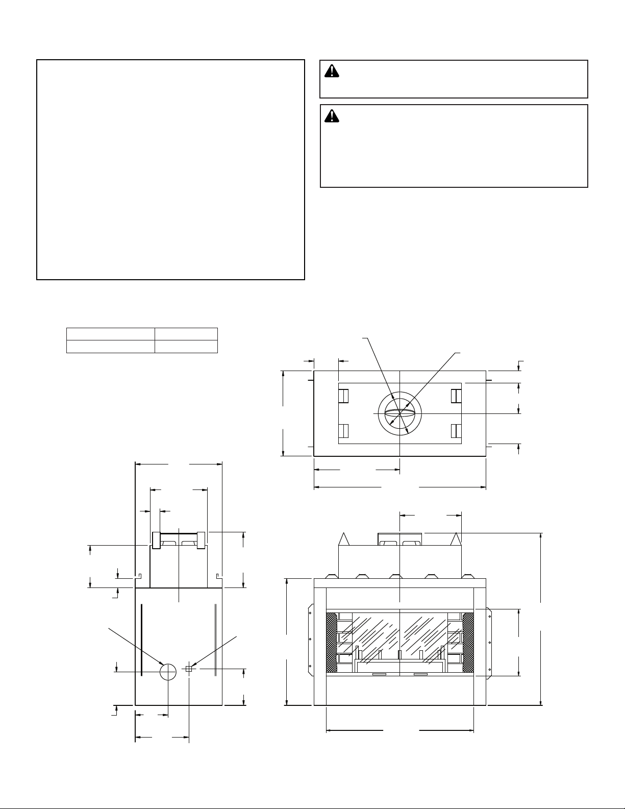
PRODUCT DIMENSIONS
MODEL CATALOG NO.
Windsor STP2 F0703
6"
(153 mm)
WARNING: Always leave glass doors fully opened
or fully closed when operating fireplace.
WARNING: Children and adults should be alerted
to the hazards of high surface temperatures and to
stay away to avoid burns or clothing ignition. Young
children should be carefully supervised when in the
same room as fireplace.
15”
(381 mm)
O.D.
TOP VIEW
12-3/8”
(315 mm)
2-1/2”
(64 mm)
12"
(305 mm)
1-1/2”
(38 mm)
OUTSIDE AIR
LEFT SIDE
VIEW
24"
(610 mm)
19"
(483 mm)
4-1/2”
(115 mm)
16"
(407 mm)
GAS LINE
CONDUIT
11-1/4”
(286 mm)
24"
(610 mm)
37-1/2”
(953 mm)
21-3/8”
(543 mm)
9-1/2”
(242 mm)
42-5/8”
(1083 mm)
15-1/2”
(394 mm)
54"
(1372 mm)
20-1/2”
(521 mm)
10-1/4”
(261 mm)
7"
(178 mm)
12"
(305 mm)
FRONT VIEW
36-1/2”
(927 mm)
Figure 1 - Dimensions
4
Astria.us.com
126653-01_E
Page 5
FIREPLACE INSTALLATION
Spacers on Sides of Fireplace
SELECTING LOCATION
To determine safest and most efficient location for fireplace, you
must take into consideration the following guidelines:
1. The location must allow for proper clearances (see Figure 2).
2. Consider a location where the fireplace will not be affected by
drafts, air conditioning ducts, windows or doors.
3. A location that avoids the cutting of joists or roof rafters will
make installation easier.
4. If an outside air kit is to be installed, accessibility to outside
combustion air must be considered. This can also be achieved
through a vented crawl space in some cases (see Optional
Outside Air Kit on page 7).
5. If gas line is to be installed, consider location of gas supply.
6. Do not connect this fireplace to a chimney system other than
an IHP chimney system.
7. Install in an area providing ventilation and adequate combustion air.
8. Due to high temperatures, do not locate this firebox in high
traffic areas or near furniture or draperies.
9. Provide adequate clearances around air openings into combustion chamber. NEVER obstruct front opening of firebox or flow
of combustion and ventilation air.
10. Do not locate in or near an area where gasoline or other flammable liquids may be stored. The firebox area must be kept clear
and free from these combustible materials.
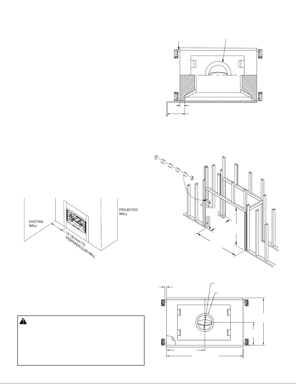
The typical installation for this fireplace is a projected installation
which allows you to extend the fireplace any distance into the room. A
projection may be ideal for a new addition on an existing, finished wall.
Provide Required 1" (2.5 cm)
Clearance
3" (7.6 cm)
12" (30.4 cm) Min. From Perpendicular
Side Wall to Fireplace Opening (Typ.)
2" (5 cm) Min. Clearance
From Pipe to Combustibles
Figure 3 - Firebox Clearances
FRAMING
1. Frame opening for fireplace using dimensions shown in Figures
4, 5 and 6 on pages 5 and 6.
*A header
must be
installed after
fireplace is set
in place
Figure 2 - Common Location of Fireplace
MINIMUM CLEARANCE TO COMBUSTIBLES
Back and sides of fireplace 1" (26 mm) minimum*
Adjacent wall 12" (305 mm) minimum
Chimney outer pipe surfaces 2" (51 mm) minimum
Bottom of fireplace to floor 0" (0 mm) minimum
WARNING: DO NOT PACK REQUIRED AIR SPACES
WITH INSULATION OR OTHER MATERIALS.
Do not obstruct fireplace openings (ie. louvers, etc.)
with any type of facing material. Combustible material must not be in contact with back of front face of
fireplace.
126653-01_E
Astria.us.com
*38 3/4"
(98.43 cm)
(60.96 cm)
44
3
(113.67 cm)
/4"
Figure 4 - Framing Firebox
15" (38.1 cm) DIA. OD
1" (2.5 cm) MIN.
TO COMBUSTIBLES
3
21
/8" (54.29 cm)
5
42
/8" (108.27 cm)
OUTER PIPE
Figure 5 - Framing Clearances
24"
2" (5.1 cm) MIN. CLEARANCE
FROM OUTER PIPE TO COMBUSTIBLES
54"
(137.16 cm)
(60.96 cm)
12"
(30.48 cm)
24"
5
Page 6
FIREPLACE INSTALLATION Continued
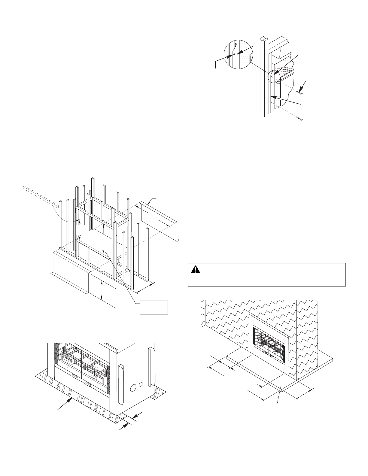
HEARTH EXTENSION
2. If fireplace is to be installed directly on carpeting, tile or any
combustible material other than wood flooring, fireplace must
be installed upon a metal or wood panel extending full width and
depth of fireplace.
3. Set fireplace directly in front of this opening and slide unit back
until nailing flanges touch side framing.
4. Check level of fireplace and shim with sheet metal if necessary.
5. Before securing fireplace to prepared framing, ember protector
(provided) must be placed between hearth extension (not supplied) and under bottom front edge of fireplace to protect against
glowing embers falling through (see Figure 7). If fireplace is to
be installed on a raised platform, a Z-type ember protector (not
supplied) must be fabricated to fit your required platform height
(see Figure 6). The ember protector should extend under fireplace
a minimum of 1 1/2". The ember protector should be made of
galvanized sheet metal (28 gauge minimum) to prevent corrosion.
6. Using screws or nails, secure fireplace to framing through flanges
located on sides of fireplace (see Figure 8).
"Z" Type
Ember Protector
*A header
must be
installed after
fireplace is set
in place
*38
3
(98.43 cm)
/
4
"
54"
(137.16 cm)
Min.
(Not Supplied)
44
3
(113.67 cm)
/
4
"
Min.
Nailing
Flanges
1" Clearance is
Not Required at
Nails or
Screws
Nailing Flanges
Prepared
Framing
Figure 8 - Nailing Flanges
HEARTH EXTENSIONS
A hearth extension projecting a minimum of 16" in front of and a
minimum of 8" beyond each side of fireplace opening is required to
protect combustible floor construction in front of fireplace. Fabricate a hearth extension using a material which meets the following
specifications: a layer of noncombustible, inorganic material having
a thermal conductivity of k = .84 BTU IN/FT2 HR °F (or less) at 1"
thick. For example, if material selected has a k factor of 0.25, such
as glass fiber, the following formula would apply:
0.25 x 1.0" = 0.30" thickness required
0.84
Thermal conductivity "k" of materials can be obtained from manu-
facturer or supplier of noncombustible material.
If hearth extension is to be raised, a “Z” type ember protector must
be used (see Figure 6 and Figure 10, page 7).
As Required by Design as Long
as Ceiling Clearance Is Maintained
24"
(60.96 cm)
Platform Must be
Solid, Flat and
Fully Supported
Figure 6 - Framing Firebox with “Z” Type Ember Protectors
Ember Protector
(Typ. 2 of 2)
1/2" (1.2 cm)
Max.
Figure 7 - Ember Protectors
WARNING: Hearth extension is to be installed
only as shown in Figure 9.
8" MIN.
(20.3cm)
36
1
/
2
" MIN.
(92.7cm)
52
1
/
2
" MIN.
(133.3cm)
NONCOMBUSTIBLE
Figure 9 - Hearth Extension
16" MIN.
(40.6cm)
6
Astria.us.com
126653-01_E
Page 7
FIREPLACE INSTALLATION Continued
)
2" (51 mm) x 4" (102 mm)
Front
Face
1-1/2" (38 mm)
Seal Gaps with
Adhesive
(10.1 cm)
Material Must
Noncombustible
Hearth Extension
8" (204 mm
Max.
1-1/2" (39 mm) Typ.
Noncombustible
Hearth Extension
1
1-
/2" (39 mm) Typ.
Figure 10 - Raised Hearth Extension
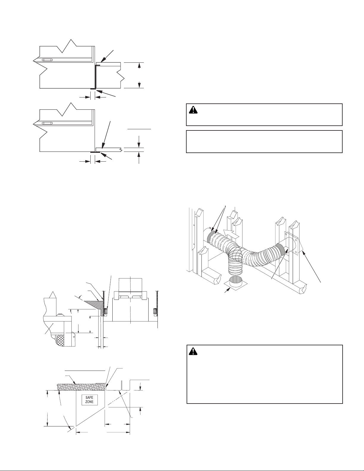
MANTEL CLEARANCES
Woodwork such as wood trims, mantels or any other combustible
material projecting from the front face must not be placed within 9"
of firebox effective opening.
Combustible materials above and projecting more than 1 1/2" from the
firebox front face (see Figure 11) must not be placed less than 12"
from effective opening of the firebox (NFPA 211, Section - Clearance
from Combustible Material).
Mantels or any other combustible material may also come up to the
side edge of the black metal face of the firebox only if the projection
from the front face falls within limits shown in Figure 12.
“Z” Type Ember
Protector
“k” Factor
.84
Ember
Protector
VENTING INSTALLATION
OPTIONAL OUTSIDE AIR KIT (MODELS AK4 OR AK4F)
The installation of an outside air kit should be performed during
the rough framing of the fireplace due to the nature of it’s
location. Outside combustion air is accessed through and exterior
wall (AK4) or a vented crawl space (AK4F). See Figure 13 and
Accessories on page 16.
Avoid installing outside air eyebrow in areas where inlet opening
may be blocked by snow, bushes or other obstacles. It should also
be located beyond the reach of children.
CAUTION: Combustion air inlet ducts shall not
terminate in attic space.
The maximum height for the air vent can not exceed
3 feet below the flue gas outlet of the termination.
For further details on installation of outside air kit, please refer to
instructions included with air kit. For operating instructions, please
refer to your owner’s manual.
Secure to Collars with Metal Tape, Screws
or Straps (Min. of 1/4" x 20" in size)
Air Inlet
Location
Must
Allow For
Bushes or
Snow
Stud
Drywall
Combustible
Materials
33°
6" (153mm)
Nom.
12"
(305 mm)
9"
Min.
(229 mm)
Min.
Fireplace Side View
3" (77 mm) Nom.
Figure 11 - Mantel Clearances to Combustible Materials
Drywall
4"
(Approx.)
33°
Nom.
Top View of Fireplace
6" Nom.
(15.2 cm)
3
4
/8"
Min.
(11.1 cm)
Noncombustible
Mortar or
3
2
/4" Max.
(6.98 cm)
Combustible
Not Overlap
Black Metal
Front Face
Figure 12 - Mantel Clearances to Metal Face
126653-01_E
Vented Crawl Space (Check
Local Codes Before Installing
in a Vented Crawl Space)
CHIMNEY PIPE
be applied by the installer to all chimney pipe
sections but is not required on sections that will
be visible after the installation is complete. Label
must wrap around the circumference of the pipe.
See accessories, page 18 for Kit F2659.
Astria.us.com
Air Inlet
Eyebrow
Vent Hood
Required
for Wall
Installation
Figure 13 - Air Kit Installation
WARNING: Label part number 900599-01 must
7
Page 8
VENTING INSTALLATION Continued
)
The IHP chimney system is a snap-lock, double-wall pipe. It consists
of a stainless steel inner flue pipe(s), a galvanized outer pipe and a
wire spacer. Each section of pipe comes in lengths of 12", 18", 36"
and 48". The actual lineal gain for each is measured after each section
is fully connected. Lineal gain is the actual measurable length of a
part after two or more parts are connected.
LINEAL GAIN
PART NO. DESCRIPTION GAIN
Windsor STP2 See-Through Fireplace 52 3/4"
48-12DM
48-12TM
36-12DM
48-12TM
24-12DM
48-12TM
18-12DM
48-12TM
12-12DM
48-12TM
STL-12D
RLT-12D
Flue Pipe 46 5/8"
Flue Pipe 34 5/8"
Flue Pipe 22 5/8"
Flue Pipe 16 5/8"
Flue Pipe 10 5/8"
Chase Style
Termination
Round Top
Termination
1" to 12"
7
"
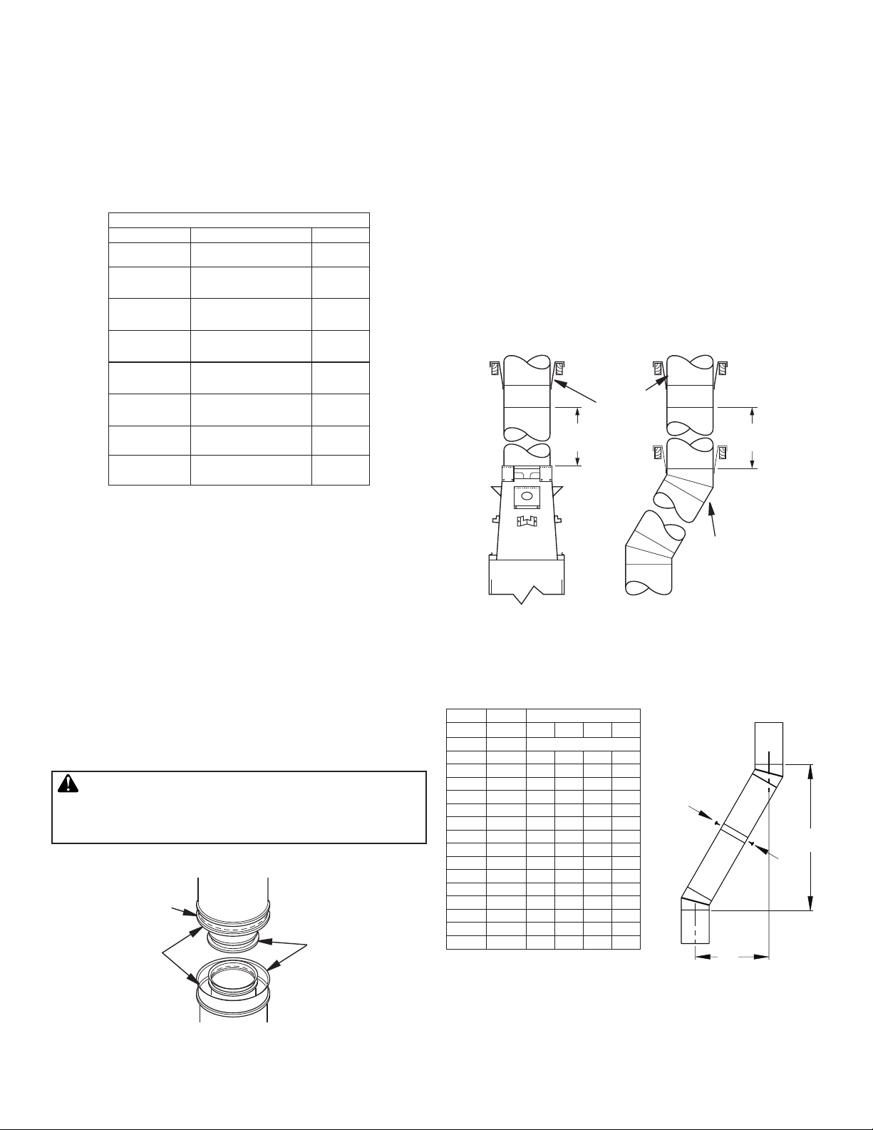
USING ELBOW OFFSETS AND SUPPORTS
Chimney weight above offset rests on return elbow. Straps must be
securely nailed to rafters or joists (see Figure 15).
To achieve desired offset, you may install combinations of 12", 18",
36" and 48" length of double wall pipe (see offset chart and Figure 16).
Maximum length of pipe between supports is 6 feet of angled run. A
maximum of two 6 feet angled run sections per chimney system (see
Figure 18).
SUPPORT SECTIONS
The chimney support section is a 4-strap 12" length of pipe. The height
of a vertical chimney pipe supported ONLY by the fireplace, must not
exceed 20 feet. Chimney heights above 20 feet must be supported.
12S-8DM
Support
20 FT.
(6.096m)
Required
20 FT.
(6.096m
PIPE INSTALLATION
The pipe sections must be assembled independently as the chimney
is installed. When connecting chimney directly to the fireplace, the
inner flue pipe section must be installed first with the lanced side up.
The outer pipe section can then be installed over the flue pipe section
with the hemmed end up. Press down on each pipe section until the
lances securely engage the hem on the fireplace starter. The wire will
assure the proper spacing between the inner and outer pipe sections.
Continue to assemble chimney sections as outlined above, making
sure that both the inner and outer pipe sections are locked together.
When installing double wall snap-lock chimney together, it is important to assure the joint between the chimney sections is locked. Check
by pulling chimney upward after locking. The chimney will not come
apart if properly locked. It is not necessary to add screws to keep the
chimney together (exception, see Figure 17, page 9).
WARNING: The opening in collar around chimney
at top of fireplace must not be obstructed. Never use
blown insulation to fill chimney enclosure.
15" Galvanized
Outer Pipe
12 3/8'' Stainless
Inner Pipe Lanced
Side Up
Hemmed End
Figure 15 - Elbow Offset
OFFSET
RISE CHIMNEY LENGTH
A B 48" 36" 18" 12"
4 3/8" 16 3/8"
9 1/2" 25 1/4"
12 1/2" 30 3/8"
14 3/8" 34"
17 5/8" 39 1/4"
21 1/2" 46"
22 3/4" 48 1/8"
26 3/8" 54 7/8"
26 3/8" 60"
31 3/4" 63 3/4"
34 3/4" 69"
38 5/8" 75 5/8"
39 7/8" 77 7/8"
43 3/4" 84 1/2"
46 3/4" 87 3/4"
48 7/8" 93 3/8"
ELBOW SET ONLY
1
1
1 1
1
1 2
1
1 1
1 1
1 1
2
1 1 1
1 1
2 1
2
OFFSET CHART
Return
Elbow
2
Screws
B
A
Figure 16 - Raise and Offset
Figure 14 - Pipe Connection
8
Astria.us.com
126653-01_E
Page 9

VENTING INSTALLATION Continued
2" (5.1cm)
RETURN
Straps
RETURN
ELBOW
OFFSET
ELBOW
Minimum
Angled Firestop
Ceiling
Support
Return
Elbow
Figure 17 - Chimney Supports
6' MAX
(15.2cm)
OFFSET
ELBOW
RETURN
ELBOW
6' MAX
(15.2cm)
CEILING
SUPPORT
PIPE
V12S-8DM
6' MAX
(15.2cm)
6' MAX
(15.2cm)
ELBOW
6' MAX
(15.2cm)
6' MAX
(15.2cm)
OFFSET
ELBOW
RETURN
ELBOW
Firestop
Spacer
Screws or Staples
(Min. of 8)
Existing
Ceiling Frame
Figure 20 - Firestop Spacer with Attic Space Above Ceiling
IMPORTANT NOTICE
When penetrating a ceiling into an attic, a firestop
thimble (FST10) is required to avoid intrusion by insulation and recommended to negotiate a joist (see
Figure 20a).
Firestop Thimble FST10
Figure 18 - Typical Offset Installations
FIRESTOP SPACERS (FS-10)
Firestop spacers are required at each point where the chimney penetrates
a floor or ceiling joist space. Their purpose is to establish and maintain
the required clearance between the chimney and the combustible materials. When the pipe passes through a framed opening into a living space
above, the firestop must be placed onto the ceiling from below as shown
in Figure 19.
They also provide complete separation from one floor space to another or
attic space as required by most codes. When the double wall pipe passes
through a framed opening into an attic space, the firestop must be placed
into an attic floor as shown in Figure 20.
When penetrating a floor or ceiling at an angle, use firestop spacer number
30 FS-10D (see Replacement Parts, page 15 and Accessories, page 17).
Existing
Ceiling Frame
Firestop Spacer
Screws or Staples
(Min. of 8)
Figure 20a - Firestop Thimble
10' FOOT RULE
All chimney terminations must extend a minimum of 3 feet above the
highest point where it passes through the roof and must be at least 2
feet above roof with a 10 foot horizontal span (see Figure 21).
IMPORTANT: If an exposed portion of chimney is greater than 4 feet
above the roof line, use support wires to keep chimney secure. Support
wires may be attached to outer pipe of chimney with screws, if screws
do not penetrate inner flue pipe.
Figure 19 - Firestop Spacer with Living Space Above Ceiling
126653-01_E
Astria.us.com
Figure 21- 10 Foot Rule
9
Page 10

VENTING INSTALLATION Continued
MINIMUM/MAXIMUM CHIMNEY HEIGHT
The minimum height of the chimney (measured from the base of the
fireplace to the flue gas outlet-end of pipe) is 16 feet for a straight run,
16 feet minimum for a run with 1 elbow set and 25 feet minimum for
a run with 2 elbow sets. (A set consists of one starter elbow and one
return elbow.)
Uncommon circumstances such as neighboring hills, tall trees, or
strong wind areas can cause down drafts in chimney system. In such
cases, going beyond the minimum recommended height would be
preferable to provide a better draw.
The fireplace height approved for any chimney run with this fireplace
system is 40 feet measured from bottom of firebox to flue outlet-end
of pipe (see Figure 22).
WARNING: Do not operate an unvented gas log
set in this fireplace with the chimney removed.
RTL-12D RTL-12D STL-12D
Storm
Collar
Flashing
MINIMUM
HEIGHT
15 FT.
(4.5m)
PENETRATING ROOF
To maintain a 2" clearance to pipe on a roof with a pitch, a rectangular
opening must be cut.
1. Determine center point where pipe will penetrate the roof.
2. Determine center point of the roof. Pitch is the distance the roof
drops over a given span, usually 12". A 6/12 pitch means that the
roof drops 6" for each 12" one measure horizontally down from
roof rafters.
3. Use roof opening chart (Figure 23) to determine correct opening
length and flashing required.
4. Remove shingles around opening measured. Cut out this section.
5. Add next sections of pipe until end penetrates roof line. Check to see
that proper clearances are maintained. Extend chimney by adding
sections of double wall pipe until pipe is minimum of 30" above
highest point of roof cutout. Termination and chimney must extend
a minimum of 36" above highest point where it passes through the
roof (see 10-Foot Rule and Figure 21, page 9.
19" Min.
(48.26cm)
2" Min.
(5.08cm)
2" Min.
(5.08cm)
30" Min.
(76.2cm)
2" Min.
(5.08cm)
Firestop
Spacer
MAXIMUM
HEIGHT
CHASE
TERMINATION
40 FT.
(12m)
Opening
“A”
Pitch Slope Opening "A"
Max.
Used Flashing
Model No.
Flat 0° 19" V6F-10DM
0-6/12 26.6° 23.25" V6F-10DM
6/1212/12
45° 30.75" V12F-10DM
Figure 23 - Roof Opening Measurements
FLASHING INSTALLATION
Determine flashing to be used with roof opening chart. Slide flashing
over pipe until base is flat against roof. Replace as many shingles as
needed to cover exposed area and flashing base. Secure in position
by nailing through shingles (see Figure 24). DO NOT NAIL THROUGH
FLASHING CONE.
10
Figure 22 - Maximum Chimney Height
Astria.us.com
126653-01_E
Page 11

VENTING INSTALLATION Continued
Storm Collar
Overlap
Shingles Top
Flashing Cone
Nail Only Outer
Perimeter of
Flashing
Underlap Shingles at
Bottom
Figure 24 - Flashing Installation
STORM COLLAR INSTALLATION (SC-10)
Place storm collar over pipe and slide down until it is snug against
the open edge of the flashing (see Figures 24 and 25). Apply waterproof caulking to all seams and notches around storm and also at
base around shingles.
Chimney Pipe
and Sides Only
Waterproof Caulk
Stainless Inner
Flue Pipe
Secure
Termination
to Outer
Pipe with 3
Screws
Overlap Shingles
(Top and Sides of
Flashing Base)
Figure 26 - Terminations
CHASE INSTALLATIONS
RLT-12D
Chase
Top
1" Noncombustible
Spacer
Underlap Shingles
1" Space
Apply Waterproof
Caulking
Storm Collar
Flashing
Screen
Storm Collar
Figure 25 - Storm Collar
TERMINATIONS
Standard Installation
The fireplace system must be terminated with the listed round top or
chase terminations. In any case, refer to the installation instructions
supplied with the termination.
Terminations approved for this fireplace are RLT-12D, which can be
used for flashing or chase and STL-12D for chase style termination
only. Figure 26, shows an RLT-12D round top termination.
Follow installation instructions provided with termination being used.
Flashing
CAUTION: Do not seal openings on the rooftop
flashing. Follow the installation instructions provided
with the termination being used.
Instructions for chase installations are included with the chase style
termination chosen. In a multiple chase installation, be sure to provide
adequate distance between terminations to prevent smoke spillage
from one termination to another. Terminations must be separated a
minimum of 24" center to center and stacked at a minimum vertical
height difference of 18" (see Figure 27).
Note: If a decorative shroud is to be installed, contact the manufacturer for specifications.
18"
(458 mm)
Min. Typ.
24"
(610 mm)
Min.
24"
(610 mm)
Min.
126653-01_E
Astria.us.com
Figure 27 - Multiple Chase Installation
11
Page 12

VENTING INSTALLATION Continued
OPTIONAL GAS LINE INSTALLATION
FINISHING FIREPLACE
Combustible materials, such as wallboard, gypsum board, sheet
rock, drywall, plywood, etc. may make direct contact with sides
and top around the fireplace face. It is important that combustible
materials do not overlap the face itself. Brick, glass, tile or other
noncombustible materials may overlap the front face provided they
do not obstruct essential openings like louvered slots or any other
opening. When overlapping with a noncombustible facing material,
use only noncombustible mortar or adhesive.
INSTALLING FIREPLACE FACING.
Any noncombustible material may be used for facing (glass, tile,
brick, etc.) as long as proper clearances are adhered to and fireplace
openings are not obstructed in any way (see Minimum Clearance to
Combustibles, page 5 and Figure 28).
Use only heat resistant, noncombustible mortar or adhesive when
securing facing material to front of fireplace. When placing facing at
upper edge of effective opening of fireplace, provide “L” shaped piece
of metal extending full width of opening (see Figure 28).
Secure with sheet metal screws at a distance high enough from edge
so it doesn't interfere with operation of doors. This assures that facing material will not block openings.
Noncombustible Facing Material
“L” Shaped
Metal Support
Noncombustible
Facing Material
Figure 28 - Fireplace Facing (Your Fireplace May Vary from
Do Not
Block
Opening
Illustration)
WARNING: A qualified service person must con-
nect fireplace to gas supply. Follow all local codes.
A gas line may be installed for the purpose of installing a vented
or vent-free decorative gas appliance available through your local
distributor. Use only gas piping approved by local codes. When
installing a gas line, a shutoff valve designed for installation outside
the appliance is recommended.
The gas pipe is intended for connection to a decorative gas appliance that operates using natural or propane/LP gas only. This
appliance must have an automatic shutoff device and must comply
with the Standard for Decorative Gas Appliances for Installation in
Vented Fireplace, ANSI Z21.60. ONLY UNVENTED GAS LOG SETS
WHICH HAVE BEEN FOUND TO COMPLY WITH THE STANDARD FOR
UNVENTED ROOM HEATERS, ANSI Z21.11.2, ARE TO BE INSTALLED
IN THIS FIREPLACE.
NOTICE: Before you proceed, make sure your gas supply is turned off.
Use only a 1/2" black iron pipe and appropriate fittings.
1. Remove knockout indentation on refractory or firebrick wall
located approximately 2" above the refractory hearth floor. The
knockout indentation must be firmly tapped with any solid object
such as a 1/2" dowel until it is released. Remove fragmented
portions of refractory (see Figure 29).
2. Remove gas line cover plate located on rear of fireplace and pull
out insulation from gas line conduit sleeve. Save insulation for
reuse.
3. Run 1/2" black iron gas line into the firebox through the rear at
11 1/4" from floor and through gas line conduit sleeve (if using
a raised platform, add height). Provide sufficient gas line into
firebox chamber for fitting connection (see Figure 30).
Note: Secure incoming gas line to wood framing to provide rigidity
for threaded end.
4. Repack insulation around gas line and into sleeve opening. Seal
any gaps between gas line and refractory knockout hole with
refractory cement or commercial furnace cement, Install the gas
appliance or cap off gas line if desired.
CAUTION: All gas piping and connections must be
tested for leaks after installation is completed. After
ensuring that gas valve is on, apply soap and water
solution to all connections and joints. Bubbles forming
show a leak. Correct all leaks at once. DO NOT USE
AN OPEN FLAME FOR LEAK TESTING AND DO NOT
OPERATE ANY APPLIANCE IF A LEAK IS DETECTED.
LEAK TESTING SHOULD BE DONE BY A QUALIFIED
SERVICE PERSON.
12
Note: An IHP hood must be installed when using an unvented gas
log set (see Installation Accessories on page 18).
set in this fireplace with chimney removed.
Astria.us.com
WARNING: Do not operate an unvented gas log
126653-01_E
Page 13

OPTIONAL GAS LINE INSTALLATION Continued
OPERATION AND MAINTENANCE GUIDELINES
If you install a decorative gas appliance (vented gas log), decorative
gas appliance must comply with the Standard for Decorative Gas
Appliance for Installation in Solid Fuel Burning Fireplaces, ANSI
Z21.60/CSA 2.26 or Z21.84 and shall also be installed in accordance
with ANSI Z223.1/NFPA 54 National Fuel Gas Codes (USA) and CAN/
CGA-B149.1 National Gas And Propane Installation Code (Canada).
Outside of
Fireplace
Gas Line
Conduit
Insulation
Gas Conduit
Cover
Outside of
Fireplace
Gas Line
Conduit
Repack
Insulation
Figure 29 - Gas Line Knockout
Incoming
1/2" Black
Iron Pipe
Seal
Opening
with
Refractory
Cement
Figure 30 - Gas Line Installation
Side
Firebrick
Finished Side
1/2" Dowel
Refractory
Knockout Plug
Side
Firebrick
Finished
Side
Provide Enough
Threaded End for
Fitting Connection
GLASS DOORS
Bi-fold glass doors are optional with this fireplace. Check with your
local distributor for availability.
To install glass doors, refer to installation instructions that are included with kit. When fireplace is in operation, doors must be fully
open or fully closed position only or a fire hazard may be created
(see Figure or 31).
A fireplace equipped with glass doors operates much differently
than a fireplace with an open front. A fireplace with glass doors has
a limited amount of air for combustion. Excessive heat within the
fireplace can result if too large a fire is built or if combustion air gate
is not completely open.
IMPORTANT: The following tips should be used to assure that both
fireplace and glass door retain their beauty and function properly.
• Both the flue damper and glass doors must be fully opened
before starting a fire. This will provide sufficient combustion
air and maintain safe temperatures in firebox.
• The glass must be allowed to warm slowly and evenly. The tempered glass will withstand a gradual temperature rise to 550° F,
which is more than a normal fire will generate. Such materials
as pitch/wax laden logs, very dry mill end lumber and large
amounts of paper or cardboard boxes. Always keep the fire well
back from the doors and never allow flames to contact the glass.
WARNING: FIREPLACES EQUIPPED WITH DOORS
SHOULD BE OPERATED ONLY WITH DOORS FULLY
OPEN OR DOORS FULLY CLOSED. IF DOORS ARE LEFT
PARTLY OPEN, GAS AND FLAME MAY BE DRAWN OUT
OF THE FIREPLACE OPENING, CREATING RISKS OF
BOTH FIRE AND SMOKE.
WARNING: Discontinue use of the appliance
immediately if doors are damaged and contact a
qualified installer for repair. Only doors certified
with the appliance shall be used.
WARNING: To avoid the risk of damaging fireplace
materials and increasing the risk of spreading a fire,
do not use fireplace to cook or warm food.
WARNING: If the fireplace has been used for Woodburning, firebox and chimney must be cleaned of soot,
creosote and ashes be a qualified chimney cleaner.
Creosote will ignite if heavily heated.
WARNING: When using a decorative vented gas
log, damper must be removed or permanently locked
in fully open position and glass doors must be in fully
open position.
126653-01_E
Astria.us.com
WARNING: Do not slam or strike doors. Damage
can result in a hazardous condition.
Doors Fully Closed
Firebox Front
Firebox Front
Doors Fully Opened
Figure 31 - Bi-Fold Glass Doors
13
Page 14

PUSH UP TO OPEN
OPERATION AND MAINTENANCE GUIDELINES Continued
Cleaning Glass
Clean glass with any commercial glass cleaner or soap and water.
Do not use any abrasive material to clean glass. Do not clean glass
with any cool water if glass is still hot from the fire. To remove doors,
refer to instructions included with glass door kit.
DAMPER MECHANISM
The damper control lever is located inside the fire chamber (see Figure 32). Make sure lever is cool before handling. Pull down to close
and push up to open. Damper must be open when lighting a fire.
Not doing so will cause smoke spillage into the room. When firebox
is not in use, close damper to prevent down drafts to enter room.
GRATE
OUTSIDE AIR
HANDLE
DAMPER CONTROL LEVER
PULL DOWN TO CLOSE
PULL TO CLOSE
PUSH TO OPEN
GRATE
The grate is designed to provide you with the maximum solid fuel
capacity. Do not overload grate or obstruct required air space beneath
it. Doing so may cause smoke spillage and a fire hazard. Always keep
ashes from building up under grate.
WARNING: Risk of fire! Replace grate with IHP
model 11169 (J4671) grate only. This grate has been
designed to keep the operation of your fireplace safe
and efficient.
Never obstruct flow of combustion and ventilation air. Keep front of
fireplace clear of all obstacles and materials.
CHIMNEY
Have your chimney system cleaned and inspected regularly to ensure safe
and efficient operation.
For further operating guidelines, instructions and warranty information, please refer to your homeowner's guide or contact your dealer.
WARNING: Children and adults should be alerted
to the hazards of high surface temperatures and to
stay away from these to avoid burns or clothing ignition. Young children should be carefully supervised
when they are in the same room as fireplace.
Figure 32 - Damper Operation
OUTSIDE AIR MECHANISM
The outside air handle is located at the right hand side of firebox
rear refractory (see Figure 32). Pull to close, push to open. Always
open mechanism when starting a fire. This provides adequate outside
combustion air. Close mechanism when not in use to prevent cold
air from entering room. Periodically check your outside air intake
vent hood for any possible obstructions such as snow, bushes, etc.
14
Astria.us.com
126653-01_E
Page 15

REPLACEMENT PARTS
TECHNICAL SERVICE
See Page 17 Fireplace Accessories section for replacement parts.
Use only parts supplied from the manufacturer.
Normally, all parts should be ordered through your IHP distributor
or dealer. Parts will be shipped at prevailing prices at time of order.
When ordering repair parts, always give the following information:
1. The model number of the fireplace.
2. The serial number of the fireplace.
3. The part number.
4. The description of the part.
5. The quantity required.
6. The installation date of the fireplace.
If you encounter any problems or have any questions concerning the
installation or application of this fireplace, please contact your dealer.
IHP
1769 East Lawrence Street
Russellville, AL 35654
Visit us at Astria.us.com
You may have further questions about installation, operation, or
troubleshooting. Please contact your IHP dealer for any questions
or concerns. When contacting your dealer please have your model
and serial numbers of your fireplace ready. You can also visit our
web site at Astria.us.com.
126653-01_E
Astria.us.com
15
Page 16

IMPORTANT NOTICES - CANADA
Canadian code CAN/ULC-S610-M87 and other pertinent codes
require stainless steel chimney for the installation of this
fireplace. A Cold Air Climate Kit is also required in Canada and
is recommended for cooler regions in the United States. Below,
find a list of approved stainless steel parts.
Chimney Parts List for Canada
Catalog
No.
F0953 12-12HT 12" Section Double Wall Pipe
F0954 18-12HT 18" Section Double Wall Pipe
F0955 24-12HT 24" Section Double Wall Pipe
F0956 36-12HT 36" Section Double Wall Pipe
F0957 48-12HT 48" Section Double Wall Pipe
F0958 30E-12HT 30" Offset and Return
F0959 12S-12HT Chimney Support
F0960 RLT-12HT Round Top w/ Louvers
F0961 AP-12HT Anchor Plate/Collar Assembly
F0951 CAK-12 Cold Air Collar Kit
*When ordered alone, this part cannot ship via parcel delivery
services.
Model No.
8" Hi-Temp
Woodburning Chimney
(Masonry Fireplaces)
IMPORTANT NOTICE
A manufactured shroud which has been approved by
a national testing agency for use with this fireplace
may be used if installed in accordance with the instructions by its manufacturer. A locally fabricated
shroud may be used with IHP Shroud Leg Spacer Kit
(SLK) in accordance with instructions provided with
the shroud.
NOTICE: The firebox canopy (hood) must not be modified or replaced with a canopy that may be provided
with the unvented decorative room heater.
CAUTION: THE STRUCTURAL INTEGRITY OF THE
MANUFACTURED HOME FLOOR, WALL, AND CEILING/ROOF MUST BE MAINTAINED.
WARNING: DO NOT INSTALL IN SLEEPING ROOM OF
MOBILE HOMES.
16
Astria.us.com
126653-01_E
Page 17

CAT NO. MODEL DESCRIPTION
REFRACTORY
FIREPLACE ACCESSORIES
J7026
J7024
J7025
J4671 Grate 3610ST
J5668
J4956
J6928
J6906
Refractory, Side L/R 3610ST (2 Ea.)
Refractory, Bottom 3610ST (2 Ea.)
Refractory, Side Front 3610ST(4 Ea.)
GRATE
SCREEN ASSEMBLY
Screen 19 3/8 X 21
Nut Push-On .765 X .445 X .011 Black
Rod, Screen 36L/R/LS/RS
EMBER PROTECTOR
Protector, Ember EP 36
INSTALLATION ACCESSORIES
BI-FOLD GLASS DOORS
F1025 DBP368ST 36" See Thru WB Bi-Fold Door (1 side) - Black Finish
F1026 DC368ST 36" See Thru WB Bi-Fold Door (1 side) - Platinum Finish
(Not Shown)
(Not Shown)
J0455 DG368ST 36" See-Thru WB Bi-Fold Door (1 side) - Brushed Finish
DOUBLE WALL PIPE
F0932 12-12DM 12" Section Double Wall Pipe Snap Lock
F0933 18-12DM 18" Section Double Wall Pipe Snap Lock
F0934 24-12DM 24" Section Double Wall Pipe Snap Lock
F0935 36-12DM 36" Section Double Wall Pipe Snap Lock
F0936 48-12DM 48" Section Double Wall Pipe Snap Lock
30° OFFSET AND RETURN
F0937 30E-12DM 30 Degree Offset and Return
CHIMNEY SUPPORT
F0938 12S-12DM Chimney Support above 20'
OPTIONAL OUTSIDE AIR KIT FOR FLOOR INSTALLATION
F1091 AK4 Complete Outside Air Kit w/Collars Hood & 3' Flex
OPTIONAL OUTSIDE AIR KIT FOR SIDEWALL INSTALLATION
F1093 AK4F Outside Air Kit Collar, Hood & 3' Flex for Floor Venting
126653-01_E
Astria.us.com
17
Page 18

INSTALLATION ACCESSORIES Continued
900599-01
STORM COLLAR
F0946 SC2-1 Storm Collar (1 ea.)
FIRESTOP SPACER
F0940 FS-10 2" Clearance Firestop Spacer (1ea)
F0941 30FS-10 30° Firestop Spacer (1)
ROOF FLASHING
F0942 V6F-10DM Roof Flashing 0 to 6/12 Pitch
F0943 V12F-10DM Roof Flashing 6/12 to12/12 Pitch
ROUND TOP TERMINATION
F0947 RLT-12D Round Top Termination with Louvered Screen
ECONO TOP TERMINATION
F0948 STL-12D Square TopTermination with Slip Section
ADJUSTABLE HOOD
Required when installing a vent-free gas log in this fireplace.
F1764 GA6050 Black Fireplace Hood
FIRESTOP THIMBLE
F0944 FST10 Firestop Thimble
HIGHT TEMPERATURE TOUCH-UP PAINT
J3943 Kit Touch-Up paint
LABEL-UL127-50PK
F2659
LABEL-UL127-
50PK
UL127 Venting Label - 50 PK
REFRACTORY STAIN KITS
Use the refractory stain kits to give white refractory panels a new look.
Kit includes foam roller handle, paint tray, and one can of stain. Available stain colors are
creamer (ivory), Rust (terra cotta), and Cappuccino (rosy taupe).
WARNING
HOT
•Fire Risk
•Insulation and combustibles must not touch
pipe
•Consult manual for clearance requirements
•Ensure proper connection
(Not Shown)
WARNING
HOT
•Fire Risk
•Insulation and combustibles must not touch
•Consult manual for clearance requirements
•Ensure proper connection
•Fire Risk
•Insulation and combustibles must not touch
pipe
pipe
•Consult manual for clearance requirements
•Ensure proper connection
WARNING
HOT
CappuccinoRustCreamer
H8176 BSK-CR Stain Kit (Rfry) 1 Qt. Creamer
H8177 BSK-RT Stain Kit (Rfry) 1 Qt. Rust
H8178 BSK-CP Stain Kit (Rfry) 1 Qt. Cappuccino
18
Astria.us.com
126653-01_E
Page 19

APPENDIX A
Draft Requirements
Your wood-burning appliance is dependent upon a properly functioning chimney for optimum performance. It is important to match
the wood-burning appliance to the chimney. The chimney has two
functions:
1. It draws combustion air into the appliance (without air, no fuel
will burn) and
2. It exhausts combustion by-products. Your new appliance is what
is known as a “natural draft” appliance.
The appliance depends solely on the natural draft of the chimney
system to draw combustion air into the unit. Draft is the force that
moves air from the appliance up into the chimney. The amount of
draft in your chimney depends on the length of the chimney, local
geography, nearby obstructions and other factors. Too much draft
may cause excessive temperatures in the appliance (overfiring). Slow
or inadequate draft equals poor combustion and possible smoking
problems. The following are some conditions that may contribute
to poor chimney draft:
1. A chimney too large for your appliance.
2. A chimney with not enough height to produce adequate draft.
3. A chimney with excessive height (this may allow exhaust to cool
too much before exiting, which will stall the rate the exhaust exits).
4. Offsets in the venting system are too restrictive (see Chimney
Guidelines).
Inadequate draft will cause the appliance to leak smoke into the room
through the wood-burning appliance and the chimney connector joints.
Excessive draft may cause an uncontrollable burn or a glowing red
appliance or chimney part.
Overfiring Damage - If the appliance or chimney connector glows,
you are overfiring. Other symptoms may include: Cracking, warping
or burning out of components, plated accessories may turn color,
appliance glass may develop a haze, which will not come off with
cleaning.
Overfiring of a appliance is a condition where excessive temperatures are reached, beyond the design capabilities of the appliance.
The damage that occurs from overfiring is not covered under the
manufacturer’s limited warranty.
Also see Troubleshooting on Page 20.
WARNING
Neither the manufacturer nor the seller warrants “smoke
free” operation nor are we responsible for inadequate
system draft caused by mechanical systems, general
construction conditions, inadequate chimney heights,
adverse wind conditions and/or unusual environmental
factors or conditions beyond our control.
take into account all variables within the installation and install the
appliance in such a manner that satisfies the draft requirements of
the appliance. See Chimney Guidelines to assist you in selecting the
proper venting system for your installation.
American National Standards Institute ANSI/NFPA 211, Standard
for Chimneys, Fireplaces, Vents, and Solid Fuel-Burning Appliances - See Draft Section: A chimney or vent shall be so designed
and constructed to develop a flow sufficient to completely remove all
flue and vent gases to the outside atmosphere. The venting system
shall satisfy the draft requirements of the connected appliance in
accordance with the manufacturer’s instructions.
Chimney Guidelines:
• In well insulated and weather tight homes, it may be difficult to
establish a good draft up your chimney. The poor draft is caused
by a shortage of air in the house. In this situation an Outside Air
Kit may need to be installed (See Negative Pressure Warning below and Outside Combustion Air in the Installation and Operation
manual).
Negative Pressure Warning
These appliances are not designed to be operated in a negative
pressure. In very airtight homes with large kitchen exhaust fans,
furnace cold air returns, fresh air exchange systems and any other
air system in close proximity to the heating appliance may create a
negative pressure in the same room as the heating appliance. This can
create dangerous back drafting of the appliance and chimney joints,
drawing combustion by-products into the home. Be sure your home
has adequate makeup air to eliminate negative pressures caused by
the above-mentioned sources. Outside air connected to the appliance
probably will not resolve such a problem as the appliance is not the
source of negative pressure. IHP accepts no liability for damages
resulting from negative pressures described here.
Ventilation Requirements - Provide adequate air for combustion.
The fresh air requirements of this appliance must be met within the
space where it will be installed. Ventilation is essential when using
a solid-fuel-burning appliance. In well insulated and weather tight
homes, it may be difficult to establish a good draft up the chimney
(caused by a shortage of air in the home). The lack of air is caused
by many common household appliances which exhaust air from the
home (such as a furnace, heat pump, air conditioner, clothes dryer,
exhaust fans, fireplaces, and other fuel burning appliances). Also, the
combustion process of this appliance uses oxygen from inside the
dwelling. If the available fresh air delivery in the dwelling is insufficient
to support the demands of these appliances, problems can result
(i.e. excessive negative pressure can develop in the dwelling which
will affect the rate at which this appliance can draft thus resulting
in performance problems or smoking. To correct this problem it
may help to open a window (preferably on the windward side of the
house) or install an outside air kit.
Selecting the Proper Venting System
The appliance is merely one component of a larger system. The
other equally important component is the venting system. This is
necessary for achieving the required flow of combustion air to the fire
chamber and for safely removing unwanted combustion by products
from the appliance.
If the venting system’s design does not promote these ends, the system
may not function properly. Poorly functioning venting systems may
create performance problems as well as be a safety hazard. A draft
test should read greater than .04’ W.C. (inches water column) and
less than .08” W.C. As per NFPA-211 standard, the installer must
126653-01_E
Astria.us.com
19
Page 20

APPENDIX A Continued
Smoking – Causes And Troubleshooting
To reduce the likelihood of smoking when opening the door, open
the combustion air control or damper before opening the door.
Your appliance has been designed and tested to provide smoke free
operation. Occasionally, there may be a small amount of smoking
upon lighting the fire, until the chimney heats up but this should not
continue. If the appliance continues to smoke it is probably for one
of the following reasons:
A. Negative pressure in the house -
As the fire burns, air goes up the chimney. This air must be
replaced through leakage into the house or through the outside
air duct. When operating the appliance, open a nearby window
temporarily to check if there is adequate replacement air supply.
B. Blowers operating (e.g.: range hood) - These blowers draw air
out of the house and may actually cause a negative pressure in
the house. Turn off all blowers and open a nearby window to
determine if this is the cause of the problem.
C. Wet wood - Wet or tarred wood will smoulder and smoke instead
of burning properly.
Your dealer can help you determine if you
have properly seasoned wood for burning.
D. Dirty or blocked chimney - Check to make sure the chimney is
clear and clean.
If dirty call a certified chimney sweep or use a
properly sized chimney brush to clean.
E. Chimney not long enough - The minimum chimney height is
twelve (12) feet (3.7 m) not including the appliance height. The
chimney must extend at least three (3) feet (915 mm) above
its point of contact with the roof and at least two (2) feet (610
mm) higher than any roof or wall within ten (10) feet (3 m) of
it. When installed with offsets, the minimum chimney height
is fifteen (15) feet. Additional height will increase draft and will
decrease the tendency to smoke.
F. Poor chimney draft - With no fire, there should be sufficient draft
to exhaust cigarette smoke introduced under the baffle or flue baffle.
Chimneys installed against an outside wall without protection may
generate back draft problems which will cause start-up problems.
To prevent this, open a nearby window, roll up a piece of paper
and light it. Then, hold it in the upper part of the firebox to warm
up the chimney. Wait until the draft is sufficient, then start the fire.
G. Blower for forced air kit operating (some models) - Make
sure that the blower is in the “off” position when you open the
appliance door for reloading.
Locating The Appliance
The best location to install your appliance is determined by considering the location of windows, doors, and the traffic flow in the room
where the appliance is located, allowing space in front of the unit for
the hearth extension and the mantel, and taking into consideration
the location of the hot air ducts (some models), outside air kit and
chimney.
If possible, you should choose a location where the chimney will pass
through the house without cutting floor or roof joists.
When selecting the location, the chimney outlet position and the
direction of the wind are important factor affecting the chimney performance. To allow a maximum draft and to reduce wind turbulence,
the chimney must:
• Penetrate the highest part of the roof.
• Be installed as far as possible of roof offsets, trees or any other
obstructions that may cause wind turbulence and back drafts in
the chimney.
• The least amount of offsets (elbows) possible. NOTE: A maximum
of 2 offsets is allowed.
Location Recommended
Marginal Location
Wind Direction
Tree
Location
Recommended
Outside Air
Intake
Facing the Wind
Figure 1
Not
Location
Not
Recommended
Prohibited Fuels
These appliances are designed to burn natural well-seasoned wood.
The wood fuel should be air dried seasoned hardwoods, as compared
to softwoods or to green or freshly cut hardwoods. Burning artificial
logs, in some model appliances is allowed (see Installation and Operation manual); please read and follow the instructions provided by
the manufacturer. DO NOT BURN:
• Garbage;
• Lawn clippings or yard waste;
• Materials containing rubber,
including tires;
• Materials containing plastic;
• Waste petroleum products,
paints or paint thinners, or
asphalt products;
• Materials containing asbestos;
• Construction or demolition
debris;
• Railroad ties or pressure-treated wood; woods that
have been dipped in tar, pitch,
pine tar, creosote, etc.
• Manure or animal remains;
• Salt water driftwood or
other previously salt water
saturated materials;
• Unseasoned wood;
• Christmas tree branches;
• Paper products, colored
paper, cardboard, plywood,
or particleboard;
• Gasoline;
• Naphtha;
• Engine Oil;
• Flammable Liquids;
• Solvents;
• Grease; or
• Charcoal or Coal
NOTE: The use of a firewood moisture meter is recommended
to ensure the firewood contains less than 20% moisture.
Seasoning Guide
Softwoods - 6 months to 18 months
Hardwoods - 12 months to 24 months
Logs that are 5” diameter across or larger should be split in half,
three pieces if over 8 inches, and four pieces when over a foot
across. If a tree has been dead for 2 - 4 years it still needs to be
cut, split, and seasoned for 6 to 24 months depending on the wood.
Standard
Cord of
Wood
4 Ft.
(1.2M)
4 Ft. (1.2M)
4'
4'
Figure 2
8 Ft.
8'
(2.4M)
20
Astria.us.com
126653-01_E
Page 21

NOTES
______________________________________________________
______________________________________________________
______________________________________________________
______________________________________________________
______________________________________________________
______________________________________________________
______________________________________________________
______________________________________________________
______________________________________________________
______________________________________________________
______________________________________________________
______________________________________________________
______________________________________________________
______________________________________________________
______________________________________________________
______________________________________________________
______________________________________________________
______________________________________________________
______________________________________________________
______________________________________________________
______________________________________________________
______________________________________________________
______________________________________________________
______________________________________________________
______________________________________________________
______________________________________________________
______________________________________________________
______________________________________________________
______________________________________________________
______________________________________________________
______________________________________________________
______________________________________________________
______________________________________________________
______________________________________________________
______________________________________________________
126653-01_E
Astria.us.com
21
Page 22

NOTES
______________________________________________________
______________________________________________________
______________________________________________________
______________________________________________________
______________________________________________________
______________________________________________________
______________________________________________________
______________________________________________________
______________________________________________________
______________________________________________________
______________________________________________________
______________________________________________________
______________________________________________________
______________________________________________________
______________________________________________________
______________________________________________________
______________________________________________________
______________________________________________________
______________________________________________________
______________________________________________________
______________________________________________________
______________________________________________________
______________________________________________________
______________________________________________________
______________________________________________________
______________________________________________________
______________________________________________________
______________________________________________________
______________________________________________________
______________________________________________________
______________________________________________________
______________________________________________________
______________________________________________________
______________________________________________________
______________________________________________________
22
Astria.us.com
126653-01_E
Page 23

Innovative Hearth Products
®
Astria
Brand Wood-Burning Fireplace
20 Year Limited Warranty
THE WARRANTY
Innovative Hearth Products ("IHP") 20 Year Limited Warranty warrants your Astria® brand wood burning fireplace ("Product") to be free from defects in materials and workmanship at the time of manufacture. The Product body, firebox and ceramic glass carry the 20 Year Limited Warranty. Ceramic glass carries the 20 Year Limited Warranty
against thermal breakage only. After installation, if covered components manufactured by IHP are found to be defective in materials or workmanship during the 20 Year
Limited Warranty period and while the Product remains at the site of the original installation, IHP will, at its option, repair or replace the covered components. If repair or
replacement is not commercially practical, IHP will, at its option, refund the purchase price or wholesale price of the IHP product, whichever is applicable. IHP will also
pay IHP prevailing labor rates, as determined in its sole discretion, incurred in repairing or replacing such components for up to five years. THERE ARE EXCLUSIONS AND
LIMITATIONS to this 20 Year Limited Warranty as described herein.
COVERAGE COMMENCEMENT DATE
Warranty coverage begins on the date of purchase. In the case of new home construction, warranty coverage begins on the date of first occupancy of the dwelling or six
months after the sale of the Product by an independent IHP dealer/distributor, whichever occurs earlier. The warranty shall commence no later than 24 months following the
date of product shipment from IHP, regardless of the installation or occupancy date.
EXCLUSIONS AND LIMITATIONS
This 20 Year Limited Warranty applies only if the Product is installed in the United States or Canada and only if operated and maintained in accordance with the printed
instructions accompanying the Product and in compliance with all applicable installation and building codes and good trade practices.
This warranty is non-transferable and extends to the original owner only. The Product must be purchased through a listed supplier of IHP and proof of purchase must be
provided. The Product body and firebox carry the 20 Year Limited Warranty from the date of installation. Vent components, trim components, paint and applied stains are
excluded from this 20 Year Limited Warranty. The following do not carry a 20 Year Limited Warranty but are warranted as follows:
Air tubes, baffles and brick retainers – Repair or replacement for one year from the date of installation
Cast iron parts – Replacement for one year from date of installation
Electrical components – Repair or replacement for one year from the date of installation
Fireplace screens, refractory and side shields (metal or refractory) – Repair or replacement for two years from date of installation. Excludes hairline cracks.
Fuel grates –These parts are considered consumable accessories and therefore are not warranted, with the exception of defects in material or workmanship which
are covered for 90 days from the date of installation
Gaskets – Replacement for one year from date of installation
Gold & nickel plating – Replacement for two years from date of installation. Excludes tarnishing
Optional glass doors – Repair or replacement for 90 days from the date of installation
Labor coverage – Prevailing IHP labor rates apply for the warranty period of the component.
Parts not otherwise listed carry a 90 day warranty from the date of installation.
Whenever practicable, IHP will provide replacement parts, if available, for a period of 10 years from the last date of manufacture of the Product.
IHP will not be responsible for: (a) damages caused by normal wear and tear, accident, riot, fire, flood or acts of God; (b) damages caused by abuse, negligence, misuse, or
unauthorized alteration or repair of the Product affecting its stability or performance. (The Product must be subject to normal use with approved fuels listed in the Operation
Manual provided with the product. This includes burning such fireplace fuels as wood and natural or propane gas. Fuel products with abnormal burning characteristics,
including but not limited to fuel such as driftwood, coal or plywood and wood products using a binder may burn at excessive temperatures and may cause damage to the
Product or may cause it to function improperly.); (c) damages caused by failing to provide proper maintenance and service in accordance with the instructions provided with
the Product; (d) damages, repairs or inefficiency resulting from faulty installation or application of the Product.
Coverage of this 20 Year Limited Warranty is conditional upon use of an adequate fuel grate on factory-built fireplaces only, when applicable.
IHP is not responsible for inadequate fireplace system draft caused by air conditioning and heating systems, mechanical ventilation systems, or general construction conditions which may generate negative air pressure in the room in which the appliance is installed. Additionally IHP assumes no responsibility for smoking conditions caused by
inadequate chimney height, adjoining trees or buildings, adverse wind conditions or unusual environmental factors and conditions. Certain IHP Products are listed for use with
Security Chimneys International, Ltd. or IHP chimney systems only. Use of chimney components other than that specified in the Product manual will void the Product warranty.
This 20 Year Limited Warranty covers only parts and labor as provided herein. In no case shall IHP be responsible for materials, components or construction which are
not manufactured or supplied by IHP or for the labor necessary to install, repair or remove such materials, components or construction. Additional utility bills incurred due
to any malfunction or defect in equipment are not covered by this 20 Year Limited Warranty. All replacement or repair components will be shipped F.O.B. from the nearest
stocking IHP factory.
LIMITATION ON LIABILITY
It is expressly agreed and understood that IHP’s sole obligation and the purchaser’s exclusive remedy under this warranty, under any other warranty, expressed or implied,
or in contract, tort or otherwise, shall be limited to replacement, repair, or refund, as specified herein.
In no event shall IHP be liable for any incidental or consequential damages caused by defects in the Product, whether such damage occurs or is discovered before or after
replacement or repair, and whether such damage is caused by IHP’s negligence. IHP has not made and does not make any representation or warranty of fitness for a particular
use or purpose, and there is no implied condition of fitness for a particular use or purpose.
IHP makes no expressed warranties except as stated in this 20 Year Limited Warranty. The duration of any implied warranty is limited to the duration of this expressed warranty.
No one is authorized to change this 20 Year Limited Warranty or to create for IHP any other obligation or liability in connection with the Product. Some states and provinces
do not allow the exclusion or limitation of incidental or consequential damages, so the above limitations or exclusions may not apply to you. The provisions of this 20 Year
Limited Warranty are in addition to and not a modification of or subtraction from any statutory warranties and other rights and remedies provided by law.
INVESTIGATION OF CLAIMS AGAINST WARRANTY
IHP reserves the right to investigate any and all claims against this 20 Year Limited Warranty and to decide, in its sole discretion, upon the method of settlement.
To receive the benefits and advantages described in this 20 Year Limited Warranty, the appliance must be installed and repaired by a licensed contractor approved by IHP.
Contact IHP at the address provided herein to obtain a listing of approved dealers/distributors. IHP shall in no event be responsible for any warranty work done by a
contractor that is not approved without first obtaining IHP's prior written consent.
HOW TO REGISTER A CLAIM AGAINST WARRANTY
In order for any claim under this warranty to be valid, you must contact the IHP dealer/distributor from which you purchased the product. If you cannot locate the dealer/
distributor, then you must notify IHP in writing. IHP must be notified of the claimed defect in writing within 90 days of the date of failure. Notices should be directed to the
IHP Warranty Department at 1769 East Lawrence Street; Russellville, AL 35654 or visit our website at WWW.ASTRIA.US.COM.
Printed in U.S.A. © 2013 Innovative Hearth Products
126653-01_E
P/N 900202-00, Rev. B 02/2018
Astria.us.com
Innovative Hearth Products
1769 East Lawrence Street • Russellville, AL 35654
23
Page 24

Astria.us.com
P126653 01
Record the following important information about your fireplace:
Fireplace model number
Fireplace serial number
Date fireplace was Installed
Dealer name
Innovative Hearth Products reserves the right to make changes at any time, without notice, in
design, materials, specifications, prices and also to discontinue colors, styles and products.
Consult your local distributor for fireplace code information.
Printed in U.S.A. © 2014 Innovative Hearth Products LLC
P./N 126653-01 Rev. E 07/2018
1769 East Lawrence Street • Russellville, AL 35654
 Loading...