

Astria Fireplaces BlueRidge18MN, BlueRidge24MP, Acadia24MP, Sequoia18MN, Sequoia18MP Installation And Operation Instructions Manual
...Page 1
Installation and Operation Instructions
PFS
US
AstriaTM Vented Gas Log Appliance
P/N 126891-01 Rev.A 02/2014
P126891-01
Models
®
BlueRidge18MN
BlueRidge18MP
BlueRidge24MN
BlueRidge24MP
Acadia18MN
Acadia18MP
Acadia24MN
Acadia24MP
Sequoia18MN
Sequoia18MP
Sequoia24MN
Sequoia24MP
INSTALLER: Leave this manual with the appliance.
CONSUMER: Retain this manual for future reference.
This appliance may be installed in an aftermarket permanently located, manufactured (mobile) home, where not
prohibited by local codes. This appliance is only for use with the type of gas indicated on the rating plate. This
appliance is not convertible for use with other gases.
f i r e - p a r t s . c o m
WARNING: This appliance is for installation only in
a solid-fuel burning masonry or UL127 factory-built
fireplace, constructed of noncombustible material
and connected to a working flue. (See page 6 for
minimum flue opening.)
WARNING: This is a gas-fired heater. It uses air (oxygen) from the room in which it is installed. Provisions
for adequate combustion and ventilation air must be
provided. Refer to the National Fual Gas Codes, ANSI
Z233.1/NFPA 54, Section 5.3 for Combustion and
Ventilation.
WARNING: If the information in these instructions is not followed exactly, a fire or explosion may result
causing property damage, personal injury or loss of life.
— Do not store or use gasoline or other flammable vapors and liquids in the vicinity of this or any other
appliance.
— WHAT TO DO IF YOU SMELL GAS:
• Do not try to light any appliance.
• Do not touch any electrical switch; do not use any phone in your building.
• Immediately call your gas supplier from a neighbor’s phone. Follow the gas supplier’s instructions.
• If you cannot reach your gas supplier, call the fire department.
— Installation and service must be performed by a qualified installer, service agency or the gas supplier.
Page 2
TABLE OF CONTENTS
f i r e - p a r t s . c o m
Safety .................................................................. 2
Local Codes......................................................... 4
Product Identication ........................................... 4
Unpacking............................................................ 5
General Information ............................................. 5
Installation ........................................................... 5
Operation ........................................................... 10
Inspecting Burners..............................................11
Cleaning and Maintenance ................................ 12
SAFETY
Troubleshooting ................................................. 13
Specications .................................................... 15
Wiring Diagram .................................................. 15
Technical Service............................................... 15
Parts .................................................................. 16
Replacement Parts ............................................ 18
Accessories ....................................................... 18
Warranty ............................................................ 19
WARNING: Improper installation, adjustment, alteration,
service or maintenance can
cause injury or property damage.
Refer to this manual for correct
installation and operational
procedures. For assistance or
additional information consult
a qualified installer, service
agency or the gas supplier.
WARNING: This appliance
is for installation only in a
solid-fuel burning masonry or
UL127 factory-built replace,
constructed of noncombstible
material and connected to a
working ue. (See page 6 for
This appliance may be installed
in an aftermarket,* permanently
located, manufactured (mobile)
home, where not prohibited by
local codes.
This appliance is only for use
with the type of gas indicated on
the rating plate. This appliance
is not convertible for use with
other gases.
* Aftermarket: Completion of sale, not for
purpose of resale, from the manufacturer
State of Massachusetts: The
installation must be made by a
licensed plumber or gas tter
in the Commonwealth of Mas-
sachusetts.
minimum ue opening.
WARNING: This product con-
WARNING: This is a gas-
red heater. It uses air (oxygen)
from the room in which it is installed. Provisions for adequate
tains and/or generates chemicals
known to the State of California
to cause cancer or birth defects
or other reproductive harm.
combustion and ventilation air
must be provided. Refer to the
National Fuel Gas Codes, ANSI
WARNING: Keep ue open
when operating unit.
Z233.1/NFPA 54, Air for Combustion and Ventilation.
IMPORTANT: Read this owner’s
manual carefully and completely
before trying to assemble, operate
or service this log set. Improper
use of this log set can cause serious injury or death from burns,
re, explosion, electrical shock
and carbon monoxide poisoning.
www.Astria.US.com
126891-01A2
Page 3
SAFETY
f i r e - p a r t s . c o m
Continued
DANGER: Carbon monoxide
poisoning may lead to death!
Carbon Monoxide Poisoning: Early signs
of carbon monoxide poisoning resemble the
u, with headaches, dizziness or nausea. If
you have these signs, the log set may not be
working properly. Get fresh air at once! Have
log set serviced. Some people are more affected by carbon monoxide than others. These
include pregnant women, people with heart
or lung disease or anemia, those under the
inuence of alcohol and those at high altitudes.
Natural & LP Gas: Natural & LP gas are
odorless. An odor-making agent is added
to the gas. The odor helps you detect a gas
leak. However, the odor added to the gas
can fade. Gas may be present even though
no odor exists.
Make certain you read and understand all
warnings. Keep this manual for reference. It
is your guide to safe and proper operation of
this log set.
WARNING: Installed decorative glass door enclosures must
be fully opened when operating
this gas appliance.
Due to high temperatures, the
appliance should be located out
of trafc and away from furniture
and draperies.
Do not place clothing or other
ammable material on or near
the appliance. Never place any
objects on the heater.
Log set assembly becomes very
hot when running. Keep children
and adults away from hot surface
to avoid burns or clothing ignition. This log set will remain hot
for a time after shutdown. Allow
WARNING: Any change to
surface to cool before touching.
this log set or its controls can
be dangerous.
WARNING: Do not use a blow-
er insert, heat exchanger insert or
other accessory not approved for
use with this appliance.
WARNING: This appliance is
equipped for either natural gas
or propane/LP gas but not both.
Gas type is indicated on the rating plate. Field conversion is not
permitted.
Carefully supervise young children when they are in the room
with appliance.
You must operate this log set with
a replace screen in place. Make
sure replace screen is closed
before running this log set.
The screen shall have openings
for introduction of combustion
air.
Keep the appliance area clear
and free from combustible
WARNING: Do not allow fans
to blow directly into the replace.
materials, gasoline and other
ammable vapors and liquids.
Avoid any drafts that alter burner
ame patterns.
Children and adults should be
alerted to the hazard of high temperature and should stay away to
avoid burns or clothing ignition.
126891-01A 3
www.Astria.US.com
Page 4
SAFETY
f i r e - p a r t s . c o m
Continued
1. This appliance, as supplied, is only for use
with the type of gas indicated on the rating
plate. This appliance is not convertible for
use with other gases.
2. Do not place propane/LP supply tank(s)
inside the structure. Locate propane/
LP supply tank(s) outdoors (propane/LP
units only).
3. If you smell gas
• shut off gas supply
• do not try to light any appliance
• do not touch any electrical switch; do not
use any phone in your building
• immediately call your gas supplier from
a neighbor’s phone. Follow the gas sup-
plier’s instructions
• if you cannot reach your gas supplier,
call the re department
4. Never install the log set
• in a recreational vehicle
• where curtains, furniture, clothing or other
ammable objects are less than 42" from
the front, top or sides of the log set.
• in high trafc areas
• in windy or drafty areas
5. Before installing in a solid fuel burning replace, the chimney ue and rebox must
be cleaned of soot, creosote, ashes and
loose paint by a qualied chimney cleaner.
Creosote will ignite if highly heated. Inspect
chimney ue for damage. If damaged, repair
ue before operating appliance.
6. If replace has glass doors, never operate
with glass doors closed, If you operate
heater with doors closed, heat buildup
inside replace will cause glass to burst.
Also if replace opening has vents at the
bottom, you must open the vents before
operating appliance.
7. To reduce the creation of soot, follow the
instructions in Cleaning and Maintenance,
page 12.
8. Do not run appliance
• where ammable liquids or vapors are
used or stored
• under dusty conditions
9. Do not burn solid fuel in the replace after
installing the log set. Do not use this log
set to cook food or burn paper or other
objects.
10. Log set becomes very hot when in use.
Keep children and adults away from hot
surface to avoid burns or clothing ignition.
Log set will remain hot for a time after shutdown. Allow surface to cool before touching.
11. Carefully supervise young children when
they are in the room with the log set.
12. Do not use appliance if any part has been
exposed to or under water. Immediately
call a qualied service technician to inspect
the room heater and to replace any part
of the control system and any gas control
which has been under water.
13. Turn log set off and let cool before servic-
ing, installing or repairing. Only a qualied
service person should install, service or
repair log set.
14. Provide adequate clearances around
air openings.
15. The installation of these appliances in
manufactured homes in the U.S. must
conform with the Manufactured Home
Construction and Safety Standard, Title
24 CFR, Part 3280, in the United States,
or when such a standard is not applicable,
Manufactured Home Installations Standard, ANSI/NCSBCS A225.1/NFPA 501A.
LOCAL CODES
Install and use log set with care. Follow all
local codes. In the absence of local codes,
use the latest edition of the National Fuel Gas
Code ANSI Z223.1/NFPA 54*
*Available from:
American National Standards Institute, Inc.
1430 Broadway
New York, NY 10018
National Fire Protection Association, Inc.
Battery march park
Quincy, MA 02269
These gas log sets are certified by PFS
Corporation to Z21.60/CGA 2.26 as a vented
decorative gas log set.
www.Astria.US.com
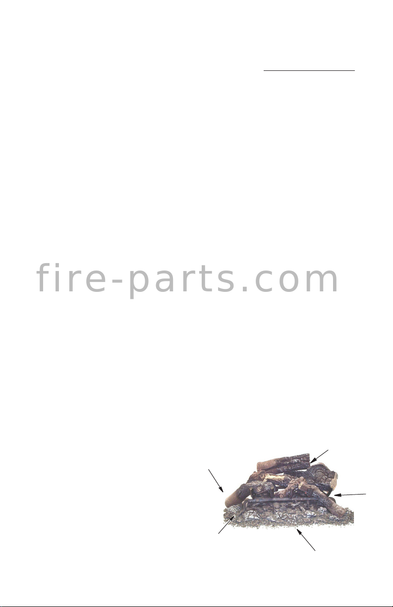
PRODUCT
IDENTIFICATION
Left
Side
Floor
Media Kit
Figure 1 - Product Identication
Log Set
Assembly
Right
Side
Front
126891-01A4
Page 5
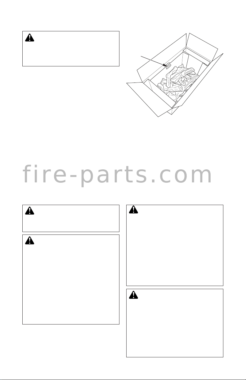
UNPACKING
f i r e - p a r t s . c o m
CAUTION: Do not remove data
plates from grate assembly. Data
plates contain important warranty
and safety information.
1. Remove log set by lifting tray handles. Set
tray on oor.
2. Remove contents from side compartments (see Figure 2).
3. Remove log set from tray by cutting
zip ties.
4. Check heater for any shipping damage.
If heater is damaged call INNOVATIVE
HEARTH PRODUCTS at 1-800-655-2008
for replacement parts before returning to
dealer.
These vented decorative gas log sets incorpo-
rate uni-body constructed ceramic ber logs
and ember bed burner which glow realistically
when the appliance is in operation.
These units are remote controlled-decorative
rated and are equipped with millivolt gas
valves. The remote control allows for ame
height adjustment, timer and on/off control.
GENERAL INFORMATION
INSTALLATION
Carton Tray
with Handles
Figure 1 - Log Set in Packing Box
A spark ignition system (piezo) allows the gas
pilot to be lit without the use of matches or
batteries and permits operation of the heater
during a power outage.
These log sets come with a Floor Media Kit
included. This kit is used to blend the oor and
the log set together for a more natural look.
WARNING: A qualied service person must install heater.
Follow all local codes.
CAUTION: This heater creates
warm air currents. These currents
move heat to wall surfaces next
to heater. Installing heater next
WARNING: Before installing
in a solid fuel burning replace,
the chimney ue and rebox
must be cleaned of soot, creosote, ashes and loose paint by a
qualied chimney cleaner. Creosote will ignite if highly heated. A
to vinyl or cloth wall coverings or
operating heater where impurities
(such as, but not limited to, tobacco smoke, aromatic candles,
cleaning uids, oil or kerosene
lamps, etc.) in the air exist, may
discolor walls or cause odors.
dirty chimney ue may create and
distribute soot within the house.
Inspect chimney ue for damage.
If damaged, repair ue damper
before operating appliance.
WARNING: Special care is
required if you are installing the
unit into a sunken replace. You
must raise the replace oor to
allow access to gas log controls.
This will insure adequate air
ow and guard against sooting.
Raise the replace oor using
noncombustible material.
126891-01A 5
www.Astria.US.com
Page 6
INSTALLATION
f i r e - p a r t s . c o m
Continued
CHECK GAS TYPE
Use the correct gas type (natural or propane/
LP) for your unit. If your gas supply is not
correct, do not instal in replace. Call dealer
where you bought the appliance for proper
type of appliance.
WARNING: This appliance is
equipped for either natural gas
or propane/LP gas but not both.
Gas type is indicated on the rating plate. Field conversion is not
permitted.
FLUE OPENING SPECIFICATIONS
Note: This vented appliance must be installed
only in a solid-fuel burning replace with a
working ue and constructed of noncombustible material. The replace chimney must have
a permanent vent opening to outside of not
less than 29 square inches or as determined
from manufacturer's installation instructions.
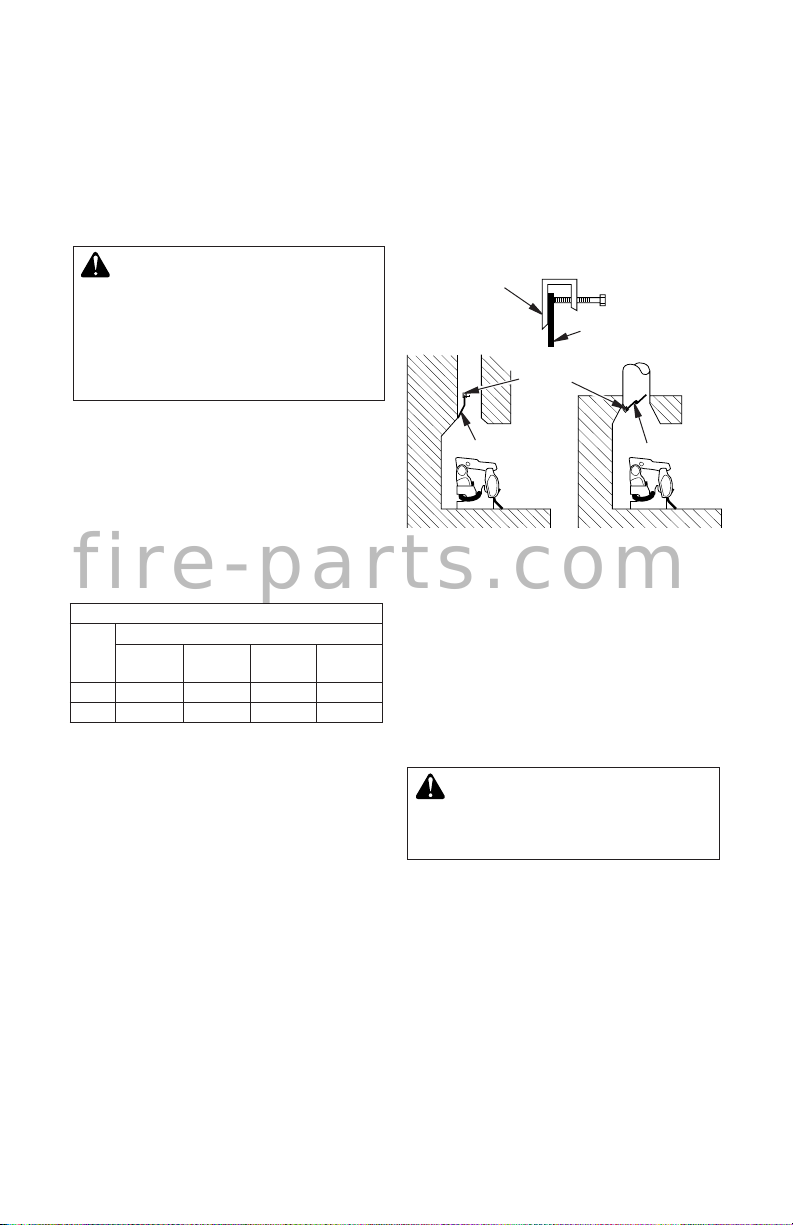
LOG SIZING REQUIREMENTS
MINIMUM FIREBOX SIZE
LOG
HEIGHT DEPTH
SIZE
18" 14" 16" 30" 20"
24" 18" 18" 34" 24"
FRONT
WIDTH
VENTING SPECIFICATIONS FOR
INSTALLATION
The replace chimney ue and vent must
be drafting properly. To check the vent for
proper drafting: Light a tightly rolled newspaper on one end and place it at the inside front
edge of the replace. Observe the smoke and
be sure the vent is properly drawing it up the
chimney. If the smoke spills out into the room,
extinguish the ame and remove any obstruc-
tion until proper venting is achieved.
The chimney ue damper must be xed open
to provide a minimum of 29 square inch ue
opeining at all times during operation of the
log set. A damper clamp can be used to
secure the damper (see Accessories, page
18). See the National Fuel Gas Code ANSI
Z223.1/NFPA 54, Section 6.6 for details about
minimum ue size.
REAR
WIDTH
INSTALLING DAMPER CLAMP
Secure the damper stop clam to the edge of
the damper as shown in Figure 2. If for any
reason this clamp doesn't work on your replace, another suitable clamp or permanent
stop must be installed, or the damper blade
must be cut or removed.
Damper
Clamp
Damper
Damper
Clamp
Damper
Masonry
Fireplace
Figure 2 - Attaching Damper Clamp
Damper
Manufactured
Fireplace
PLACEMENT OF APPLIANCE
Center the appliance in the replace. Make
certain the grate front feet sit inside the front
edge of the replace and that there is adequate clearance around the appliance for
access and operation.
CONNECTING TO GAS SUPPLY
WARNING: A qualied service
person must connect heater to
gas supply. Follow all local codes.
Installation Items Needed
Before installing heater, make sure you have
the items listed below.
• external regulator (propane/LP models
only)
• piping (check local codes)
• sealant (resistant to propane/LP gas)
• equipment shutoff valve
• test gauge connection
• sediment trap
• tee joint
• pipe wrench
www.Astria.US.com
126891-01A6
Page 7
INSTALLATION
f i r e - p a r t s . c o m
Continued
For propane/LP units, the installer must
supply an external regulator. The external
regulator will reduce incoming gas pressure.
You must reduce incoming gas pressure to
between 11 and 14 inches of water column.
If you do not reduce incoming gas pressure,
heater regulator damage could occur. Install
external regulator with the vent pointing down
as shown in Figure 3. Pointing the vent down
protects it from freezing rain or sleet.
WARNING: Connecting
directly to an unregulated propane/LP tank may cause an
explosion.
The appliance gas inlet connection is 3/8"
NPT at the regulator, located at the rear of
the appliance.
IMPORTANT: Hold appliance regulator with a
wrench to prevent movement when connect-
ing to inlet piping.
IMPORTANT: Install equipment shutoff valve in
an accessible location. The equipment shutoff
valve is for turning on or shutting off the gas to
the appliance.
Apply pipe joint sealant lightly to male NPT
threads. This will prevent excess sealant from
going into pipe. Excess sealant in pipe could
result in clogged heater valves.
WARNING: Use pipe joint
sealant that is resistant to liquid
petroleum (LP) gas.
Install a sediment trap (not supplied with log
set) where it is within reach for cleaning. Install
in piping system between fuel supply and
heater. Locate sediment trap where trapped
matter is not likely to freeze. A sediment trap
captures moisture and contaminants. This
keeps them from going into heater controls.
If sediment trap is not installed or is installed
wrong, heater may not run properly.
CAUTION: Use only new,
black iron or steel pipe. Internally-tinned copper tubing may
be used in certain areas. Check
your local codes. Use pipe of
1/2" diameter or greater to allow
proper gas volume to heater. If
pipe is too small, undue loss of
volume will occur.
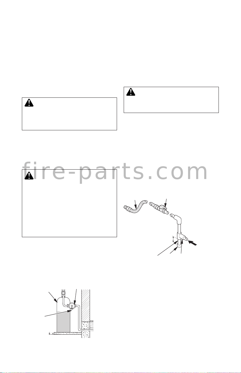
Installation must include an equipment shutoff
valve, union and plugged 1/8" NPT tap. Locate
NPT tap within reach for test gauge hook up.
NPT tap must be upstream from log set (see
Figure 4).
Propane/LP
Supply Tank
Vent
Pointing
Down
Figure 3 - External Regulator with Vent
Pointing Down
126891-01A 7
External
Regulator
www.Astria.US.com
Approved Flexible
Gas Hose (If
allowed by local
codes)
3" Minimum
Pipe Cap Tee
Nipple Joint
Figure 4 - Gas Connection
* Purchase the optional shutoff valve from
your dealer.
** Minimum inlet pressure for purpose of input
adjustment.
Equipment Shutoff Valve
with 1/8" NPT Tap*
Natural
From Gas
Meter (5" W.C.**
to 10.5" W.C.
Pressure)
Propane/LP
From External
Regulator (11"
W.C.** to 14"
W.C. Pressure)
Page 8

INSTALLATION
f i r e - p a r t s . c o m
Continued
CHECKING GAS CONNECTIONS
WARNING: Test all gas piping
and connections for leaks after
installing or servicing. Correct
all leaks at once.
WARNING: Never use an
open ame to check for a leak.
Apply a noncorrosive leak detec-
tion uid to all joints. Bubbles
forming show a leak. Correct all
leaks at once.
PRESSURE TESTING GAS SUPPLY
PIPING SYSTEM
Test Pressures In Excess Of 1/2 PSIG
(3.5 kPa)
1. Disconnect appliance with its appliance
main gas valve (control valve) and equipment shutoff valve from gas supply piping
system. Pressures in excess of 1/2 psig
(3.5 kPa) will damage heater regulator.
2. Cap off open end of gas pipe where equipment shutoff valve was connected.
3. Pressurize supply piping system by either
opening propane/LP supply tank valve
for propane/LP gas or opening main gas
valve located on or near gas meter for
natural gas or using compressed air.
4. Check all joints of gas supply piping system. Apply noncorrosive leak detection
uid to all joints. Bubbles forming show
a leak.
5. Correct all leaks at once.
6. Reconnect heater and equipment shutoff
valve to gas supply. Check reconnected
ttings for leaks.
Test Pressures Equal To or Less Than
1/2 PSIG (3.5 kPa)
1. Close equipment shutoff valve (see Figure 5).
2. Pressurize supply piping system by either
opening propane/LP supply tank valve
for propane/LP gas or opening main gas
valve located on or near gas meter for
natural gas or using compressed air.
3. Check all joints from gas meter to equipment shutoff valve for natural gas or
propane/LP supply to equipment shutoff
valve for propane/LP (see Figure 6 or 7).
Apply noncorrosive leak detection uid to
all joints. Bubbles forming show a leak.
4. Correct all leaks at once.
Equipment
Shutoff
Valve
Figure 5 - Equipment Shutoff Valve
Propane/LP
Supply Tank
Figure 6 - Checking Gas Joints
(Propane/LP Gas Only)
Gas Meter
Figure 7 - Checking Gas Joints
Gas Pressure Check
The appliance regulator controls the burner
pressure which should be checked at the
pressure test point (1/8" NPT plugged tap)
located near the on the control valve identi-
ed OUT for the manifold side and IN for inlet
pressure. Make sure operating pressures
are within the limits shown in Specications,
page 15.
Equipment Shutoff Valve
Equipment Shutoff Valve
(Natural Gas Only)
Open
Closed
Control Valve
Location
Control Valve
Location
www.Astria.US.com
126891-01A8
Page 9

INSTALLATION
f i r e - p a r t s . c o m
Continued
The pressure should be checked with the
unit burning and set to High. Replace test
point plug or tighten test screw after pressure
measurement ensuring no gas leaks.
PLACEMENT OF FLOOR MEDIA
WARNING: Do not add extra
logs or ornaments such as pine
cones or vermiculite. Using
these added items can cause
sooting. Use only the material
included in the kits.
3. Place ber log pieces randomly on lava
rock and ember material around unit (see
Figure 10).
4. Use remaining lava rock to blend the
oor media together. Your nished effect
should resemble Figure 11.
WARNING: Failure to posi-
tion the oor media as shown in
Figures 8 through 11 or failure
to use only parts specically
approved with this appliance
may result in property damage
or personal injury.
WARNING: Do not place lava
rock, embers or ber log pieces on
logs or burners. This may cause
sooting. Place oor media material
only on the replace oor.
1. Place lava rock around base of unit making
sure the burner ports and valve access are
not blocked (see Figure 8). Retain a small
amount of lava rock to be used in step 4.
2. Place ember ake material around front
and sides of unit close to (but NOT on)
the burner (see Figure 9).
Figure 10 - Placing Fiber Log Pieces
Figure 8 - Placing Lava Rock
Figure 9 - Placing Ember Flake Material
126891-01A 9
www.Astria.US.com
Figure 11 - Floor Media Kits Installed
Page 10

OPERATION
f i r e - p a r t s . c o m
The RF Millivolt valve control used on these
appliances allows you to turn the gas log set
on or off; use a timer to automatically operate
the log set; increase or decrease ame height,
fan speed or timing. An easy-to-read display
gives you information about room temperature,
set temperature, ame height level, fan speed
level and a countdown timer, as well as a low
battery indication. Figure 12 shows the location
of the controls and indicators for the transmitter
(remote) and the receiver (valve).
Note: Fan operations are not applicable to
these Hardwood Series.
TRANSMITTER/REMOTE
Display
Mode
Button
Timer
Button
RECEIVER/VALVE
Up Arrow
Down Arrow
Piezo
Manual
Switch
Figure 12 - RF Millivolt Valve Controls
with Transmitter/Remote
FOR YOUR SAFETY
READ BEFORE LIGHTING
WARNING: Keep ue open
when operating unit.
WARNING: If you do not fol-
low these instructions exactly,
a re or explosion may result
causing property damage, personal injury or loss of life.
PilotStat
Knob
LED
A. This appliance has a pilot which must
be lighted with a piezo ignitor. When
lightning the pilot, follow these instruc-
tions exactly.
B. BEFORE LIGHTING smell all around
the appliance area for gas. Be sure to
smell next to the oor because some
gas is heavier than air and will settle
on the oor.
WHAT TO DO IF YOU SMELL GAS
• Do not try to light any appliance.
• Do not touch any electric switch; do
not use any phone in your building.
• Immediately call your gas supplier
from a neighbor’s phone. Follow the
gas supplier’s instructions.
• If you cannot reach your gas supplier,
call the re department.
C. Use only your hand to push in or turn
gas control knob. Never use tools. If
the knob will not push in or turn by
hand, do not try to repair it, call a quali-
ed technician. Force or attempted
repair may result in a re.
D. Do not use this appliance if any part
has been under water. Immediately
call a qualied service technician to
inspect the appliance and to replace
any part of the control system and
any gas control which has been under
water.
LIGHTING
INSTRUCTIONS
NOTICE: During initial operation
the appliance will emit a slight
odor for an hour or two. This is
due to the "burn-in" of the internal paints and lubricants used
in manufacturing. For the rst
few hours, operate the appliance
with doors and windows open to
encourage dissipation of odor.
1. STOP! Read the safety information, beginning in column 1.
2. Make sure equipment shutoff valve is fully
open.
3. Set switch in the Local position.
www.Astria.US.com
126891-01A10
Page 11

OPERATION
f i r e - p a r t s . c o m
Continued
4. Wait ve (5) minutes to clear out any gas.
If you then smell gas STOP! Follow the
safety information, page 10. If you don't
smell gas, go on to the next step.
5. Turn PilotStat knob to PILOT. Push in on
PilotStat knob and press Piezo button
until the pilot is lit.
6. Continue to hold PilotStat knob in until
LED blinks (one brief blink every two
seconds) then release knob.
Note: You will need to hold the knob in for
about one minute.
7. Turn PilotStat knob to ON See Figure 12,
page 10.
WARNING: Moving the Local/Remote switch can cause
the main burner to come on
immediately. Stand away from
the main burner when moving
the local/remote switch to avoid
possible injury.
USING TRANSMITTER/
REMOTE
1. Place 3 AAA batteries in remote. (page 12)
2. Move switch to REMOTE position (see
Figure 12, page 10). Remote comes on
in Manual mode.
3. Press FLAME key on remote within 30
seconds.
4. Make sure LED display turns on for one
second.
5. Press MODE button until mode
shows in display window of transmitter/
remote. Press up or down key to change
set temperature.
6. To set delay timer, press TIMER button
followed by either the up or down key.
7. To change the ame height, press the
MODE button until mode is ON. Press
the FLAME
down arrow key.
8. To change between Fahrenheit and Celsius, press the up and down arrow keys at
the same time and hold for at least three
seconds.
button and press the up or
TO TURN OFF GAS
TO APPLIANCE
Shut Off Main Burner Using Remote
Press MODE button until mode is OFF.
Pilot stays lit.
Shut Off Main Burner Without Remote
Turn PilotStat knob to PILOT. Pilot stays lit.
Shut Off Main Burner and Pilot
Turn PilotStat knob to OFF.
CAUTION: During normal
shutdown of this unit, a ash
may be observed due to the nature of the burner components.
Remain clear of the unit during
the shutdown process.
INSPECTING BURNERS
Check pilot ame pattern and burner ame
patterns often.
Flames from the pilot should always be present when the appliance is in operation (see
Figure 13).
The ame should look similar to those in
Figure 14, page 12. The ames should look
random in appearance with the ember bed
glowing red-orange in color.
Figure 13 - Correct Pilot Flame Pattern
126891-01A 11
www.Astria.US.com
Page 12

INSPECTING BURNERS
f i r e - p a r t s . c o m
Continued
Beech Mountain Log Set Little Leaf Oak Log Set
Black Tupelo Log Set
Figure 14 - Log Sets with Flame Patterns
CLEANING AND MAINTENANCE
If, after a period of use, the ames start to
WARNING: Turn off the appliance and allow to cool before
cleaning.
CAUTION: You must keep
control areas, burners and
circulating air passageways of
replace clean. Inspect these
areas of replace before each
use. Have replace and chimney
(if applicable) inspected yearly
by a qualied service person.
Fireplace may need more fre-
quent cleaning due to excessive
lint from carpeting, bedding
material, etc.
Only limited cleaning will be required under
normal use of this appliance. Dust the front
grate and top of receiver/valve. Do not use
cleaning uids to clean logs or any other part
of the appliance.
exhibit unusual shapes and behavior or the
burner fails to ignite smoothly, then the burner
holes may require some cleaning. If this hap-
pens, we recommend that you contact your
nearest authorized service technician to get
the appliance serviced.
TRANSMITTER
If the battery light is on or the display is blank,
you will need to replace the three AAA batter-
ies in transmitter/remoter. To change batteries
in the transmitter/remote, slide the battery
compartment door off to expose old batteries.
Place new batteries into housing and reattach
door. See Figure 15.
Figure 15 - Bottom of Transmitter,
Showing Battery Compartment and Door
www.Astria.US.com
126891-01A12
Page 13

TROUBLESHOOTING
f i r e - p a r t s . c o m
Note: In normal operation, LED blinks once
every two seconds; also, LED will be on
for one second after every valid command
received by the receiver/valve' these are not
error codes.
Failure codes can occur anytime after the pilot
burner is lit. Failure code timing is 1/4 second
on, 1/2 second off.
Sequence is failure code followed by LED not
blinking for four seconds.
In the event of multiple failure codes, the next
failure code follows the previous failure code
by approximately 3 seconds.
LED Failure Code
(No. of Blinks) Service Action
8 Replace valve.
7 Conrm stepper motor
connection exists.
5 Conrm fan connection
exists and works.
3 Replace thermopiles.
2 Device too hot. Turn on fan
or if applicable, open glass
doors.
1 short blink Normal operation
LED Failure Codes and Service Action
WARNING: Turn off and unplug heater and let cool before servic-
ing. Only a qualied service person should service and repair heater.
IMPORTANT: Valve system troubleshooting should only be accomplished by a qualied service technician.
Note: Before troubleshooting the gas control system, be sure external gas shut off valve
(located at gas supply inlet) is in the "ON" position.
OBSERVED PROBLEM
Spark ignitor will not light pilot
after repeated triggering of
ignitor button
126891-01A 13
POSSIBLE CAUSE REMEDY
1. Defective ignitor (no spark
at electrode)
2. Defective or misaligned
electrode at pilot (spark
at electrode)
3. Gas supply pressure
errant
4. Pilot orice plugged
www.Astria.US.com
1. Check for spark at elec-
trode and pilot; if no spark
and electrode wire is properly connected, replace
ignitor
2. Using a match, light pilot.
If pilot lights, turn off pilot
and trigger the ignitor but-
ton again. If pilot lights,
an improper gas mixture
caused the bad lighting
and a longer purge period
is recommended. If pilot
will not light, check gap at
electrode and pilot - gap
should be 1/8" to have a
strong spark. If gap mea-
sures 1/8", replace pilot
3. Check inlet gas pressure. It
should be within the limits
as marked on the rating
plate
4. Clean or replace pilot orice
Page 14

OBSERVED PROBLEM
f i r e - p a r t s . c o m
Pilot will not stay lit after
carefully following the lighting
instructions
TROUBLESHOOTING
Continued
POSSIBLE CAUSE
1. Defective pilot generator
(thermocouple)
REMEDY
1. Check pilot ame, it must
impinge on thermocouple
(see Figure 13, page 11).
Clean and/or adjust pilot for
maximum ame impinge-
ment on thermocouple.
Ensure that the connection
between the valve and
thermocouple are tight and
secure.
Pilot burning, no gas to burner,
valve knob "ON"
Frequent pilot/burner outage
problem
1. Thermopile may not be
generating sufcient millivoltage.
2. Plugged burner orice
1. Pilot ame may be too low
or blowing (high) causing
the pilot/valve safety to
drop out
1. Check thermopile with millivolt meter. Take reading
at thermopile terminals of
gas valve. It should read
325 millivolts minimum.
Replace faulty thermopile
if reading is below specied
minimum.
2. Check burner orifice for
stoppage and remove
1. Clean and/or adjust pilot
ame for maximum ame
impingement on thermo-
couple (see Figure 13,
page 11)
www.Astria.US.com
126891-01A14
Page 15

f i r e - p a r t s . c o m
SPECIFICATIONS
BlueRidge24MN
Acadia24MN
Sequoia24MN
Btu (Variable) 45,000/67,000 43,000/65,000 41,000/56,000 42,000/51,000
Type Gas Natural Gas Only Propane/LP Only Natural Gas Only
Propane/LP Only
Ignition Piezo Piezo Piezo Piezo
Manifold Pressure 3.5" - 1.6"W.C. 10" - 6.3"W.C. 3.5" - 1.6"W.C. 10" - 6.3"W.C.
Inlet Gas Pressure (in. of water)
Maximum 10.5" W.C. 13" W.C. 10.5" W.C. 13" W.C.
Minimum* 5.0" W.C. 11" W.C. 5.0" W.C. 11" W.C.
Valve Operation RF Millivolt RF Millivolt RF Millivolt RF Millivolt
Orice Size #21 #42 #28 #45
* For purpose of input adjustment
BlueRidge24MP
Acadia24MP
Sequoia24MP
BlueRidge18MN
Acadia18MN
Sequoia18MN
BlueRidge18MP
Acadia18MP
Sequoia18MP
WIRING DIAGRAM
REMOTE CONTROL
(MILLIVOLT)
Pilot
Burner
Outlet
Pressure
Tap
Inlet
Pressure
Tap
Piezo
Pilot Tube
Assembly
Local and
Remote Switch
POWER SUPPLY. PROVIDE DISCONNECT MEANS
AND OVERLOAD PROTECTION AS REQUIRED.
Figure 16 - Millivolt System Wiring Diagram
Gas Control
Knob
Pilot
Adjustment
Screw
Thermopile
Leadwires
TECHNICAL SERVICE
You may have further questions about installation, operation, or troubleshooting. If so,
contact INNOVATIVE HEARTH PRODUCTS
at 1-800-655-2008. When calling please
126891-01A 15
www.Astria.US.com
have your model and serial numbers of your
heater ready.
You can also visit INNOVATIVE HEARTH
PRODUCT’s web site at www.IHP.US.com.
Page 16

PARTS
f i r e - p a r t s . c o m
BlueRidge18MN
BlueRidge18MP
BlueRidge24MN
BlueRidge24MP
7
3
15
Acadia18MN
Acadia18MP
Acadia24MN
Acadia24MP
8
10
16
Sequoia18MN
Sequoia18MP
Sequoia24MN
Sequoia24MP
6
9
17
5
11
12
13
1
2
www.Astria.US.com
4
126891-01A16
Page 17

This list contains replaceable parts used in your heater. When ordering parts, follow the
f i r e - p a r t s . c o m
PARTS
instructions listed under Replacement Parts on page 12 of this manual.
KEY
NO. PART NO. DESCRIPTION QTY.
1 111814-01 Gas Valve • • 1
111814-02 Gas Valve • • 1
2 115453-01 Valve/Pilot Bracket • • • • 1
3 115457-01 Log Burner • • 1
115458-01 Log Burner • • 1
4 111815-01 Transmitter/Remote • • • • 1
5 111809-01 Pilot • • 1
111809-02 Pilot • • 1
6 115490-01 Orice • 1
115490-02 Orice • 1
115490-03 Orice • 1
115490-04 Orice • 1
7 115449-01 Grate • • 1
115448-01 Grate • • 1
8 104489-01 Gasket • • • • 1
9 115491-01 Air Shutter • 1
115492-01 Air Shutter • • 1
115493-01 Air Shutter • 1
10 115454-01 Venturi • • • 1
115454-02 Venturi • 1
11 115452-01 Valve Bracket • • • • 1
12 115488-01 Tube • • • • 1
13 14396 Adapter Valve • • • • 1
14 115489-01 Adapter Orice • • • • 1
15 115450-01 Burner Plate • • 1
115451-01 Burner Plate • • 1
16 115456-01 Log Support Plate • • • • 1
17 114394-01 Pilot Shield • • • • 1
PARTS AVAILABLE NOT SHOWN
111288-02 Flex Gas Line • • • • 1
112363-01 Ember Chunk Kit #1, (3 Pieces) • • • • 1
112364-01 Ember Chunk Kit #2, (2 Pieces) • • • • 1
112799-01 Ember Flakes Kit • • • • 1
GA6060 Lava Rock • • • • 1
26839 Rock Wool • • • • 1
BlueRidge24MN
Acadia24MN
Sequoia24MN
Sequoia24MP
BlueRidge24MP
Acadia24MP
Acadia18MN
Sequoia18MP
BlueRidge18MP
Acadia18MP
Sequoia18MN
BlueRidge18MN
LOG SET ASSEMBLIES
MODELS PART NO.
BlueRidge24MN/P 115474-01
Sequoia24MN/P 115471-01
Acadia24MN/P 115473-01
BlueRidge18MN/P 115469-01
Sequoia18MN/P 115470-01
Acadia18MN/P 115472-01
126891-01A 17
www.Astria.US.com
Page 18

REPLACEMENT PARTS
f i r e - p a r t s . c o m
Note: Use only original replacement parts.
This will protect your warranty coverage for
parts replaced under warranty.
Contact authorized dealers of this product.
If they can’t supply original replacement
part(s), call INNOVATIVE HEARTH PRODUCTS at 1-800-655-2008.
When calling, have ready:
• your name
• your address
• model and serial numbers of your heater
• how heater was malfunctioning
• purchase date
Usually, we will ask you to return the part to
the factory.
ACCESSORIES
Purchase these accessories from your local
dealer. If they can not supply these accessories
call INNOVATIVE HEARTH PRODUCTS at
1-8 00-655-20 08 for information. You can also
write to the address listed on the back page of
this manual.
FIREPLACE HOOD
Black - GA6050
Antique Brass - GA6053
Helps deect heat away from mantel or wall
above replace. Fits opening 28" to 4" wide.
DAMPER CLAMP - GA6080
Permanently opens chimney ue damper for
vented operation.
LAVA ROCK - GA6060
Order when additional rock is desired (1.8 lb.
bag)
www.Astria.US.com
126891-01A18
Page 19

Innovative Hearth Products
Superior™ Brand Gas Log Set
Limited Three Year Warranty
THE WARRANTY
Innovative Hearth Products Limited Three Year Warranty ("IHP") warrants your Superior™ brand Gas Log Set ("Product") to be free from defects in materials and workmanship
at the time of manufacture. The logs and grate carry the Limited Three Year Warranty. After installation, if covered components manufactured by IHP are found to be defective in materials or workmanship during the Limited Three Year Warranty period and while the Product remains at the site of the original installation, IHP will, at its option,
repair or replace the covered components. If repair or replacement is not commercially practical, IHP will, at its option, refund the purchase price or wholesale price of the
IHP product, whichever is applicable. IHP will also pay IHP prevailing labor rates, as determined in its sole discretion, incurred in repairing or replacing such components.
THERE ARE EXCLUSIONS AND LIMITATIONS to this Limited Three Year Warranty as described herein.
COVERAGE COMMENCEMENT DATE
Warranty coverage begins on the date of installation. In the case of new home construction, warranty coverage begins on the date of first occupancy of the dwelling or six
months after the sale of the Product by an independent IHP dealer, whichever occurs earlier. The warranty shall commence no later than 24 months following the date of
product shipment from IHP, regardless of the installation or occupancy date.
EXCLUSIONS AND LIMITATIONS
This Limited Three Year Warranty applies only if the Product is installed in the United States or Canada and only if operated and maintained in accordance with the printed
instructions accompanying the Product and in compliance with all applicable installation and building codes and good trade practices.
This warranty is non-transferable and extends to the original owner only. The Product must be purchased through a listed supplier of IHP and proof of purchase must be
provided. The following do not carry the Limited Three Year Warranty but are warranted as follows:
Gas components – Repair or replacement for one year from the date of installation.
Remote control – Repair or replacement for one year from the date of installation.
Labor coverage – Prevailing IHP labor rates apply for the warranty period of the component.
Parts not otherwise listed carry a 90 day warranty from the date of installation.
Whenever practicable, IHP will provide replacement parts, if available, for a period of 10 years from the last date of manufacture of the product.
f i r e - p a r t s . c o m
IHP will not be responsible for: (a) damages caused by normal wear and tear, accident, riot, fire, flood or acts of God; (b) damages caused by abuse, negligence, misuse, or
unauthorized alteration or repair of the Product affecting its stability or performance (The Product must be subjected to normal use. The Product is designed to burn either
natural or propane gas only. Burning conventional fuels such as wood, coal or any other solid fuel will cause damage to the Product, will produce excessive temperatures
and could result in a fire hazard.); (c) damages caused by failing to provide proper maintenance and service in accordance with the instructions provided with the Product;
(d) damages, repairs or inefficiency resulting from faulty installation or application of the Product.
This Limited Three Year Warranty covers only parts and labor as provided herein. In no case shall IHP be responsible for materials, components or construction which are
not manufactured or supplied by IHP or for the labor necessary to install, repair or remove such materials, components or construction. Additional utility bills incurred due to
any malfunction or defect in equipment are not covered by this warranty. All replacement or repair components will be shipped F.O.B. from the nearest stocking IHP factory.
LIMITATION ON LIABILITY
It is expressly agreed and understood that IHP’s sole obligation and the purchaser’s exclusive remedy under this warranty, under any other warranty, expressed or implied,
or in contract, tort or otherwise, shall be limited to replacement, repair, or refund, as specified herein.
In no event shall IHP be liable for any incidental or consequential damages caused by defects in the Product, whether such damage occurs or is discovered before or after
replacement or repair, and whether such damage is caused by IHP’s negligence. IHP has not made and does not make any representation or warranty of fitness for a particular
use or purpose, and there is no implied condition of fitness for a particular use or purpose.
IHP makes no expressed warranties except as stated in this Limited Three Year Warranty. The duration of any implied warranty is limited to the duration of this expressed
warranty.
No one is authorized to change this Limited Three Year Warranty or to create for IHP any other obligation or liability in connection with the Product. Some states and
provinces do not allow the exclusion or limitation of incidental or consequential damages, so the above limitations or exclusions may not apply to you. The provisions of
this Limited Three Year Warranty are in addition to and not a modification of or subtraction from any statutory warranties and other rights and remedies provided by law.
INVESTIGATION OF CLAIMS AGAINST WARRANTY
IHP reserves the right to investigate any and all claims against this Limited Three Year Warranty and to decide, in its sole discretion, upon the method of settlement.
To receive the benefits and advantages described in this Limited Three Year Warranty, the appliance must be installed and repaired by a licensed contractor approved by IHP.
Contact IHP at the address provided herein to obtain a listing of approved dealers/distributors. IHP shall in no event be responsible for any warranty work done by a
contractor that is not approved without first obtaining LHP's prior written consent.
HOW TO REGISTER A CLAIM AGAINST WARRANTY
In order for any claim under this warranty to be valid, you must contact the IHP dealer/distributor from which you purchased the product. If you cannot locate the dealer/
distributor, then you must notify IHP in writing. IHP must be notified of the claimed defect in writing within 90 days of the date of failure. Notices should be directed to the
IHP Warranty Department at 1508 Elm Hill Pike, Suite 108; Nashville, TN 37210 or visit our website at WWW.SUPERIORFIREPLACES.US.COM.
Printed in U.S.A. © 2014 Innovative Hearth Products LLC
P/N 900247-00, Rev. NC, 01/2014
Innovative Hearth Products
1508 Elm Hill Pike, Suite 108 • Nashville, TN 37210
Page 20

KEEP THIS WARRANTY
f i r e - p a r t s . c o m
Model (
located on product or identication tag
Serial No. (
located on product or identication tag
Date Purchased __________________________
Keep receipt for warranty verication.
WARRANTY
) _____________________________
) __________________________
www.Astria.US.com
126891-01A20
Page 21

NOTES
f i r e - p a r t s . c o m
_____________________________________________________
______________________________________________________
______________________________________________________
______________________________________________________
______________________________________________________
______________________________________________________
______________________________________________________
______________________________________________________
______________________________________________________
______________________________________________________
______________________________________________________
______________________________________________________
______________________________________________________
_____________________________________________________
______________________________________________________
______________________________________________________
______________________________________________________
______________________________________________________
______________________________________________________
______________________________________________________
______________________________________________________
______________________________________________________
126891-01A 21
www.Astria.US.com
Page 22

NOTES
f i r e - p a r t s . c o m
_____________________________________________________
______________________________________________________
______________________________________________________
______________________________________________________
______________________________________________________
______________________________________________________
______________________________________________________
______________________________________________________
______________________________________________________
______________________________________________________
______________________________________________________
______________________________________________________
______________________________________________________
_____________________________________________________
______________________________________________________
______________________________________________________
______________________________________________________
______________________________________________________
______________________________________________________
______________________________________________________
______________________________________________________
______________________________________________________
______________________________________________________
______________________________________________________
______________________________________________________
______________________________________________________
_____________________________________________________
______________________________________________________
______________________________________________________
______________________________________________________
______________________________________________________
______________________________________________________
______________________________________________________
______________________________________________________
______________________________________________________
www.Astria.US.com
126891-01A22
Page 23

NOTES
f i r e - p a r t s . c o m
_____________________________________________________
______________________________________________________
______________________________________________________
______________________________________________________
______________________________________________________
______________________________________________________
______________________________________________________
______________________________________________________
______________________________________________________
______________________________________________________
______________________________________________________
______________________________________________________
______________________________________________________
_____________________________________________________
______________________________________________________
______________________________________________________
______________________________________________________
______________________________________________________
______________________________________________________
______________________________________________________
______________________________________________________
______________________________________________________
______________________________________________________
______________________________________________________
______________________________________________________
______________________________________________________
_____________________________________________________
______________________________________________________
______________________________________________________
______________________________________________________
______________________________________________________
______________________________________________________
______________________________________________________
______________________________________________________
______________________________________________________
126891-01A 23
www.Astria.US.com
Page 24

f i r e - p a r t s . c o m
P126891-01
1508 Elm Hill Pike, Suite 108
Nashville, TN 37210
1-800-655-2008
www.IHP.US.com
126891-01
Rev. A
02/14
 Loading...