

Astria Fireplaces Gemini33TMN, Gemini33REN, Gemini33RMN, Gemini33RMP, Gemini33REP Installation And Operation Instructions Manual
...
Installation and Operation Instructions
Gemini™ Direct-Vent Gas Fireplaces
P/N 900285-01 REV. F 08/2016
Ce manuel est disponible en francais, simplement
en faire la demande. Numéro de la pièce 900285-03.
P900285-01
CUS
Report No. F13-094
INSTALLER: Leave this manual with the appliance.
CONSUMER: Retain this manual for future
reference.
Models
Gemini33TMN
Gemini33TMP
Gemini33TEN
Gemini33TEP
Gemini33RMN
Gemini33RMP
Gemini33REN
Gemini33REP
GeminiCD35DEN
Gemini35DMN
Gemini35DMP
Gemini35DEN
Gemini35DEP
Gemini40DMN
Gemini40DMP
Gemini40DEN
Gemini40DEP
GeminiCD40DEN
Installateur : Laissez cette notice avec l’appareil.
Consommateur : Conservez cette notice pour
consultation ultérieure.
Gemini45DMN
Gemini45DMP
Gemini45DEN
Gemini45DEP
This appliance may be installed in an aftermarket permanently located, manufactured home (USA only)
or mobile home, where not prohibited by local codes. This appliance is only for use with the type of gas
indicated on the rating plate. This appliance is not convertible for use with other gases, unless a certifi ed kit
is used.
Cet appareil peut installé dans une maison préfabriquée (mobile) déjà installée à demeure, si les réglements
locaux le permettent. Ce appareil doit être utilisé uniquement avec le type de gaz indiqué sure la plaque
signalétique. Cet appareil ne peut être converti à d’autres gaz, sauf si une trousse de conversion est utilsée.
WARNING:
FIRE OR EXPLOSION HAZARD
Failure to follow safety warnings exactly could
result in serious injury, death, or property damage.
- Do not store or use gasoline or other fl ammable
vapors and liquids in the vicinity of this or any
other appliance.
- WHAT TO DO IF YOU SMELL GAS
• Do not try to light any appliance.
• Do not touch any electrical switch; do not use
any phone in your building.
• Leave the building immediately.
• Immediately call your gas supplier from a neighbor’s phone. Follow the gas supplier’s instructions.
• If you cannot reach your gas supplier, call the
fi re department.
- Installation and service must be performed by
a qualifi ed installer, service agency or the gas
supplier.
AVERTISSEMENT:
RISQUED’INDENDIE OU D’EXPLOSION
Le non-respect Des avertissements de sécurité
pourrait d’entraîner des blessures graves, la mort
ou des dommages matériels.
- Ne pas entreposer ni utilizer d’essence ni d’autres
vapeurs ou liquides infl ammables dans le voisinage
de cet appareil ou de tout autre appareil.
- QUE FAIRE SI VOUS SENTEZ UNE ODEUR DE GAZ:
• Ne pas tenter d’allumer d’appareil.
• Ne touchez à aucan interrupteur. Ne pas vous servir
des téléphones se trouvant dans le bâtiment où
vous trouvez.
• Sortez immédiatement de bâtiment.
• Appelez immédiatement votre fournisseur de
gaz depuis un voisin. Suivez les instructions du
fournisseur.
• Si vous ne pouvez rejoindre le fournisseur de gaz,
appelez le service des incindies.
- L’installation et l’entretien doivent être assurés par
un installateur ou un service d’entretien qualifi é
ou par le fournisseur de gaz.
Innovative Hearth Products
Gemini™ and GeminiCD Series Direct-Vent Gas Fireplaces
SAFETY AND YOUR FIREPLACE
See attached color fl yer for proper color representation
General Information
900285-01 08/2016
DANGER
A barrier designed to reduce the risk of burns from the hot viewing glass is provided with this appliance and shall be installed for the protection of children and
other at-risk individuals.
Voir ci-joint tract pour une bonne représentation de la couleur
DANGER
L’écran pare-étincelles fourni avec ce foyer réduit le risque de brûlure en cas de
contact accidentel avec la vitre chaude et doit être installé pour la protection Des
enfants et Des personnes à risques.
HOT GLASS WILL
CAUSE BURNS.
DO NOT TOUCH GLASS
UNTIL COOLED.
NEVER ALLOW CHILDREN
TO TOUCH GLASS.
VITRE CHAUDE
RISQUE DE BRÛLURES.
NE TOUCHEZ PAS UNE VITRE
NON REFROIDIE.
NE LAISSEZ JAMAIS UN ENFANT
DE TOUCHER LA VITRE.
Vea el volante adjunto para la representación de color adecuado
PELIGRO
CAUSARÁ QUEMADURAS.
TOCAR EL VIDRIO CALIENTE.
LOS NIÑOS DEBEN NUNCA
Una barrera diseñada para reducir el riesgo de quemaduras desde la mirilla (vidrio)
caliente es proveida con este aparato y deberá instalarse para la protección de los
niños y otros individuos en riesgo.
2
EL VIDRIO CALIENTE
USTED DEBE NUNCA
TOCAR EL VIDRIO.
Innovative Hearth Products
Gemini™ and GeminiCD Series Direct-Vent Gas Fireplaces
General Information
900285-01 08/2016
Safety and Your
Fireplace
All parts of your
IHP fi replace get
EXTREMELY HOT!
To prevent severe burns
and injuries, do Not
remove the barrier on the
appliance which prevents
direct contact with the
glass.
Follow the safety instructions below
and be sure everyone in your household
understands this burn hazard:
• The surfaces on your fi replace get
EXTREMELY HOT!
• The glass on the front of the
fi replace reaches EXTREMELY HIGH
temperatures and can cause severe
burns if touched.
• Keep children away from an operating
fi replace. Closely supervise children
in any room where a fi replace is
operating to prevent contact with glass.
• Keep clothing, furniture, gasoline, and
other fl ammable liquids away from the
fi replace.
• Even after the gas is turned off,
fi replace surfaces remain extremely
hot.
Be sure to attach the enclosed Safety-
in-Operation Warnings where you
turn on your fi replace, to help remind
everyone of the dangers associated with
high temperatures
Read Important Safety Information
(Page 5)
.
(Page 47)
.
La sécurité et
votre foyer
Toutes les parties de votre
foyer IHP deviennent
EXTRÊMEMENT CHAUDES !
Afi n d’éviter les brûlures
graves ou les blessures,
ne pas retirer l’écran de
protection de la foyer qui
empêche tout contact
direct avec la vitre.
Suivez les instructions de sécurité
ci-dessous et veillez à ce que tous
les membres de votre famille soient
conscients du danger de brûlure
encouru :
• Les surfaces de votre foyer deviennent
EXTRÊMEMENT CHAUDES !
• La vitre située à l'avant du foyer atteint
des températures EXTRÊMEMENT
ÉLEVÉES et peut causer de graves
blessures en cas de contact.
• Tenez les enfants à l'écart du foyer
lorsqu'il fonctionne. Surveillez
attentivement les enfants dans les
pièces où un foyer est utilisé afi n
d'éviter qu'ils ne soient en contact avec
la vitre.
• Tenez tous les vêtements, les meubles,
l'essence et tout autre liquide
infl ammable à l'écart du foyer.
• Même après fermeture du gaz, les
surfaces du foyer restent extrêmement
chaudes.
Veillez à coller les Étiquettes de mise
en garde relatives à la sécurité
d'utilisation à l'endroit où vous
utilisez le foyer, pour rappeler à tous
les utilisateurs les dangers liés aux
températures élevées
Lisez L’information de sûreté
importante (Page 5)
(Page 47)
.
.
Seguridad y su
chimenea
¡Todas las partes de la
chimenea IHP se ponen
MUY CALIENTES!
Para evitar quemaduras y lesiones
graves, no quite el protector de malla
o guardia de seguridad que evita el
contacto directo con el vidrio.
Siga las instrucciones de seguridad
a continuación y asegúrese de que
todos en su hogar sepan acerca de este
peligro de quemadura:
• ¡Las superfi cies de la chimenea se
ponen MUY CALIENTES!
• El vidrio delante de la
chimenea alcanza temperaturas
EXTREMADAMENTE ALTAS y puede
causar quemaduras graves si se toca.
• Mantenga a los niños alejados de
la chimenea en funcionamiento.
Supervise en forma cercana a los niños
en cualquier cuarto donde haya una
chimenea funcionando para impedir el
contacto con el vidrio.
• Mantenga la ropa, mobiliario, gasolina
y otros líquidos infl amables alejados
de la chimenea.
• Aún después de haber apagado el
gas, las superfi cies de la chimenea
permanecen extremadamente
calientes.
Asegúrese de colocar las Etiquetas de
advertencia de seguridad de operación
en el lugar donde enciende la chimenea,
para que todos recuerden los peligros
asociados con las altas temperaturas
(Página 47)
Lea Información importante de
seguridad (Página 5).
.
[FRENCH][ENGLISH]
[SPANISH]
3
Innovative Hearth Products
Gemini™ and GeminiCD Series Direct-Vent Gas Fireplaces
General Information
900285-01 08/2016
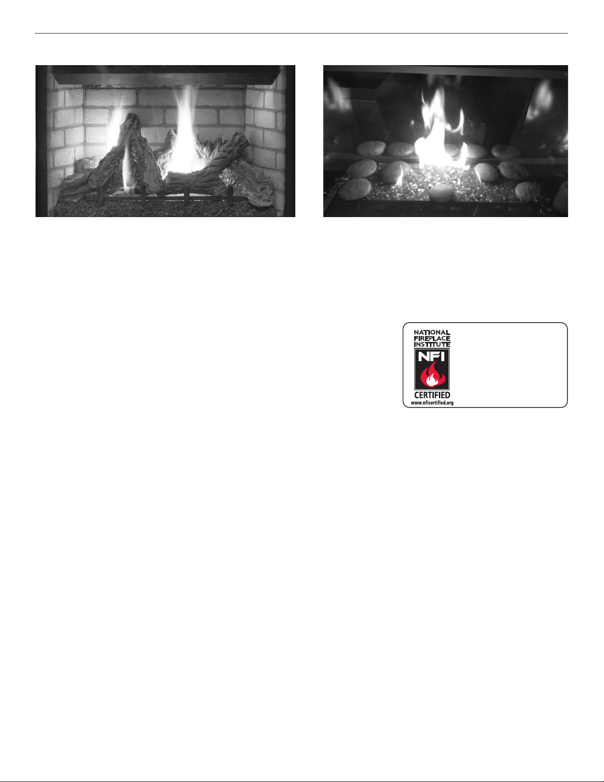
Traditional - Driftwood Logs
THANK YOU FOR YOUR PURCHASE. WE APPRECIATE YOUR BUSINESS!
Please carefully read and follow all instructions in this manual. Pay special attention to all warnings and safety
information. Following these safety, care, and operation instructions will help ensure many years of dependable and
enjoyable service from your fi replace.
Please read and understand these instructions before installing,
operating, or servicing this product.
General Information
Safety and Your Fireplace...................................................................2
Important Safety Information ............................................................5
Fireplace Installation, Operation, and Maintenance Notices ............... 6
Packaging List ...................................................................................8
Introduction ....................................................................................... 8
Gas Pressure .....................................................................................9
Requirements for the Commonwealth of Massachusetts ................10
Cold Climate Insulation ....................................................................10
Manufactured Home Requirements .................................................11
Location ...........................................................................................11
Vent Termination Clearances ...........................................................12
Minimum Clearances to Combustibles ............................................14
Wall Finishes / Surrounds / Mantels ................................................15
Installation Preparation ....................................................................15
Installation
Installation Sequence ......................................................................16
Construct the Fireplace Framing ......................................................16
Prepare the Fireplace Top Spacers ...................................................18
Route the Gas Supply Line to the Fireplace .....................................18
Vent System Preparation .................................................................21
Install the Vent System ....................................................................25
Complete the Field Wiring ................................................................37
4
Contemporary
We recommend that our
gas hearth products be
installed and serviced by
professionals who are
certied in the U.S. by the
National Fireplace Institute®
(NFI) as NFI Gas Specialists.
Install the [Optional] Blower Kit after Installation in the Framing .....39
Connect the Gas Line .......................................................................40
Verify Proper Fireplace Operation ....................................................41
Optional: Install the Firebox Liners ..................................................42
Install the Logs, Volcanic Stone, and Glowing Embers or Glass
Media ..........................................................................................42
Install the Glass Door ......................................................................42
Adjust the Air Shutter to Ensure Proper Flame Appearance .............42
Install the Hood ...............................................................................43
Install the Finishing Materials ..........................................................44
Attach the Safety-in-Operation Warnings.........................................44
Installing Batteries for Backup and Wall Switch ...............................44
Installation Accessories ................................................................... 48
Gas Conversion Kits ........................................................................50
Operation
Operation ......................................................................................... 51
Maintenance .................................................................................... 60
Accessory Components ...................................................................63
Lighting Instructions .......................................................................67
Troubleshooting ...............................................................................73
Replacement Parts ..........................................................................75
Warranty ..........................................................................................79

Innovative Hearth Products
Gemini™ and GeminiCD Series Direct-Vent Gas Fireplaces
IMPORTANT SAFETY INFORMATION
General Information
900285-01 08/2016
Important Safety Information
1. WARNING: Do not operate appliance
with the glass front removed, cracked
or broken.
2. Do not use this appliance if any part
has been under water. Immediately
call a qualifi ed service technician to inspect the appliance and to replace any
part of the control system and any gas
control which has been under water.
3. Due to high temperatures, the appliance should be located out of traffi c
and away from furniture and draperies.
4. Children and adults should be alerted
to the hazards of high surface temperature and should stay away to avoid
burns or clothing ignition.
5. Clothing or other fl ammable material
should not be placed on or near the
appliance.
6. Young children should be carefully
supervised when they are in the same
room as the appliance. Toddlers,
young children, and others may be susceptible to accidental contact burns.
A physical barrier is recommended
if there are at-risk individuals in the
house. To restrict access to a fi replace
or stove, install an adjustable safety
gate to keep toddlers, young children,
and other at-risk individuals out of the
room and away from hot surfaces.
7. Any safety screen, guard or barrier
removed for servicing an appliance
must be replaced prior to operating
the appliance.
8. Installation and repair should be done
by a qualifi ed service person. The appliance should be inspected before use
and at least annually by a professional
service person. More frequent cleaning may be required due to excessive
lint from carpeting, bedding material,
et cetera. It is imperative that control
compartments, burners, and circulating air passageways of the appliance
be kept clean. See maintenance instructions on Page 60.
L’information de sûreté
importante
1. AVERTISSEMENT. Ne pas utiliser l’appareil
si le panneau frontal en verre n’est pas en
place, est craqué ou brisé.
2. Ne pas se servir de cet appareil s’il a été
plongé dans l’eau, même partiellement.
Faire inspecter l'appareil par un technicien
qualifi é et remplacer toute partie du systéme
de contrôle et toute commande qui ont été
plongées dans l'eau.
3. En raison des températures élevées,
l’appareil devrait être installé dans un endroit où il y a peu de circulation et loin du
mobilier et des tentures.
4. Les enfants et les adultes devraient être
informés des dangers que posent les températures de surface élevées et se tenir à
distance afi n d’éviter des brûlures ou que
leurs vêtements ne s’enfl amment.
5. On ne devrait pas placer de vêtements
ni d’autres matières inflammables sur
l’appareil ni à proximité.
6. Les jeunes enfants devraient être surveillés
étroitement lorsqu’ils se trouvent dans la
même pièce que l’appareil. Les tout petits,
les jeunes enfants ou les adultes peuvent
subir des brûlures s’ils viennent en contact
avec la surface chaude. Il est recommandé
d’installer une barrière physique si des
personnes à risques habitent la maison.
Pour empêcher l’accès à un foyer ou à un
poêle, installez une barrière de sécurité
; cette mesure empêchera les tout petits,
les jeunes enfants et toute autre personne
à risque d’avoir accès à la pièce et aux
surfaces chaudes.
7. Tout écran ou protecteur retiré pour permettre l’entretien de l’appareil doit être
remis en place avant de mettre l’appareil
en marche.
8. L’installation et la réparation devrait être
confi ées à un technicien qualifi é. L’appareil
devrait faire l’objet d’une inspection par un
technicien professionnel avant d’être utilisé
et au moins une fois l’an par la suite. Des
nettoyages plus fréquents peuvent être
nécessaires si les tapis, la literie, et cetera
produisent une quantité importante de poussière. Il est essentiel que les compartiments
abritant les commandes, les brûleurs et les
conduits de circulation d’air de l’appareil
soient tenus propres. Voyez les instructions
d’entretien à la Page 60.
Información importante de
seguridad
1. ADVERTENCIA: No opere el artefacto con el
frente de vidrio quitado, agrietado o roto.
2. No use este artefacto si alguna de sus partes
ha estado bajo agua. Llame de inmediato
a un técnico de servicio califi cado para
que inspeccione el artefacto y reemplace
cualquier parte del sistema de control y
cualquier control de gas que haya estado
bajo agua.
3. Debido a las altas temperaturas, el artefacto
debe situarse fuera de las áreas de tráfi co y
lejos del mobiliario y cortinas.
4. Se debe alertar a los niños y adultos sobre
los peligros de las altas temperaturas en la
superfi cie y que se mantengan alejados para
evitar quemaduras o ignición de la ropa.
5. No debe colocarse ropa u otros materiales
infl amables sobre y cerca del artefacto.
6. Se debe supervisar de cerca a los niños
cuando estén en el mismo cuarto que el
artefacto. Los niños pequeños, los jóvenes
y otras personas pueden ser susceptibles
a quemaduras por contacto accidental. Se
recomienda instalar una barrera física si hay
personas en riesgo en la casa. Para restringir
el acceso a una chimenea o estufa, instale
una puerta de seguridad ajustable para
mantener a los niños pequeños, jóvenes y
otras personas en riesgo fuera del cuarto y
lejos de las superfi cies calientes.
7. Cualquier malla o resguardo de seguridad
quitado para dar servicio a un artefacto, debe
reinstalarse antes de operar el artefacto.
8. Una persona de servicio competente debe
realizar la instalación y reparación. Una
persona de servicio profesional debe
inspeccionar el artefacto antes de usar al
menos una vez por año. Se puede requerir
limpieza más frecuente debido a la pelusa
excesiva del alfombrado, del material de
cobijas, etc. Es imprescindible mantener
limpios los compartimientos de control, los
quemadores y los pasajes de circulación del
aire del artefacto. Ver las instrucciones de
mantenimiento en la página 60.
[English]
[French]
[Spanish]
5

Innovative Hearth Products
Gemini™ and GeminiCD Series Direct-Vent Gas Fireplaces
APPLIANCE INSTALLATION, SERVICE, AND MAINTENANCE NOTICES
WARNING
Improper installation, adjustment, alteration, service or maintenance can cause injury or
property damage. Refer to this manual. For assistance or additional information consult a
qualifi ed installer, service agency or the gas supplier.
AVERTISSEMENT
Une installation, un réglage,une modifi cation, une réparation ou un entretien mal effectué
peut causer des dommages matériels ou des blessures. Voir la notice de l’utilisateur qui
accompagne l’appareil. Pour de l’aide ou des renseignements supplémentaires, consultez
un installateur, un technicien agréé ou le fournisseur de gaz.
Only trim kit(s) supplied by the manufacturer shall be used in the installation of this fi replace.
Seules des portes certifi ées pour cet appareil doivent être utilisées.
These appliances must not be connected to a chimney or fl ue serving a separate solid fuel
burning appliance.
General Information
900285-01 08/2016
Any change to this appliance and/or its operating controls is dangerous. Improper installation
or use of this appliance can cause serious injury or death from fi re, burns, explosion or
carbon monoxide poisoning.
CARBON MONOXIDE POISONING: Early signs of carbon monoxide poisoning are similar to
the fl u with headaches, dizziness and/or nausea. If you have these signs, obtain fresh air
immediately. Turn off the gas supply to the appliance and have it serviced by a qualifi ed
professional, as it may not be operating correctly. Some people are more affected by carbon
monoxide than others, including pregnant women, people with heart or lung disease or
anemia, those under the infl uence of alcohol, and those at high altitudes.
Turn off gas and electrical power to the appliance and allow it to cool before cleaning or
servicing the appliance.
If the barrier becomes damaged, the barrier shall be replaced with the manufacturer’s barrier
for this appliance.
Si l’écran est endommagé, il doit être remplacé par celui fournit par le fabricant de cet
appareil.
For use with barrier(s) Part No(s). F1902 (33” Models), F1839 (35” Models), F1840 (40”
Models), and F1903 (45” Models). Follow installation instructions.
Reinstall any barrier removed before operating the appliance. The barrier is designed to
reduce the risk of burns from hot glass. Do not operate the appliance without the barrier
installed.
6
Innovative Hearth Products
Gemini™ and GeminiCD Series Direct-Vent Gas Fireplaces
APPLIANCE OPERATION NOTICES
These fi replaces are vented gas appliances. Do not burn wood or other material in these
appliances.
These appliances are designed to operate on natural gas or propane gas only. The use of
other fuels or combinations of fuels will degrade the performance of this system and may be
dangerous.
Provide adequate clearances around air openings and adequate accessibility clearance for
service and proper operation. Never obstruct the front openings of the appliance.
These appliances are designed as supplemental heaters. Therefore, it is advisable to have an
alternate primary heat source when installed in a dwelling.
WARRANTY INFORMATION
Your gas appliance is covered by a limited lifetime warranty. You will fi nd a copy of the
warranty accompanying this manual. Please read the warranty to be familiar with its
coverage.
General Information
900285-01 08/2016
Retain this manual. File it with your other documents for future reference.
Failure to comply with the installation and operating instructions provided will result in an
improperly installed and operating appliance, voiding its warranty.
Do not attempt to alter or modify the construction of the appliance or its components. Any
modifi cation or alteration may void the warranty, certifi cation, and listings of this unit.
IMPORTANT SAFETY AND WARNING INFORMATION
Hot while in operation. Do not touch. Severe Burns may result. Keep children, clothing
furniture, gasoline and other liquids having fl ammable vapors away.
L’appareil est chaud lorsqu’il fonctionne. Ne pas toucher l’appareil. Risque de brûlures
graves. Surveiller les enfants. Garder les vêtements, les meubles, l’essence ou autres
liquides produisant des vapeur infl ammables loin de l’appareil.
CAUTION
ATTENTION
7

Innovative Hearth Products
Gemini™ and GeminiCD Series Direct-Vent Gas Fireplaces
INSTALLATION
PACKAGING
All models include
The assembled vented gas fi replace heater is packaged with:
• Literature Kit (envelope in bottom compartment containing Installation and Operation Instructions (this manual),
Hot Glass Safety Flyer, and Safety-In-Operation Warning Labels)
• U-Shaped Vent Restrictor (attached to Literature Kit envelope)
• Hood (Inside fi rebox, Traditional Models)
• Log Set (Traditional Fireplaces, in fi rebox) or Glass Media (Contemporary Fireplaces)
• Volcanic Stone—1 bag (in bottom compartment, Traditional Models)
• Glowing Embers—1 bag (in bottom compartment, Traditional Models)
• 1 Non-combustible board, 2 side brackets and 1 center bracket
INTRODUCTION
These vented gas fi replace heaters are sealed combustion, air-circulating gas fi replaces designed for residential and
commercial applications.
Millivolt fi replaces have a millivolt gas control valve with piezo ignition system. If a blower will be installed, electrical
power must be provided at the time of fi replace installation.
Electronic fi replaces are designed with an electronic intermittent pilot ignition system. External electrical power is
required to operate these units. In the event of a power outage, four (4) AA batteries (in battery holder) provide
backup power for fi replace operation. Battery backup will not operate optional/standard blower. Traditional units
require an additional four (4) AA batteries to provide power to the split-fl ow system.
General Information
900285-01 08/2016
NOTE: Installation and repair should be done by a qualifi ed service person. The fi replace should be inspected before
use and at least annually by a professional service person. More frequent cleaning may be required due to excessive
lint from carpeting, bedding material, etcetera. It is imperative that control compartments, burners and circulating air
passageways of the fi replace be kept clean.
Remarqué : L’installation et la réparation devrait être confi ées à un technicien qualifi é. L’appareil devrait faire
l’objet d’une inspection par un technicien professionnel avant d’être utilisé et au moins une fois l’an par la suite.
Des nettoyages plus fréquents peuvent être nécessaires si les tapis, la literie, et cetera produisent une quantité
importante de pous-sière. Il est essentiel que les compartiments abritant les commandes, les brûleurs et les
conduits de circulation d’air de l’appareil soient tenus propres.
NOTE: Diagrams and illustrations are not necessarily shown to scale.
Approved Vent Components
These fi replaces are designed, tested and listed for operation and installation with the following vent components
only:
• Secure Vent® Direct-Vent System Components,
• Secure Flex® Flexible Vent Components, and
• Z-FLEX® Model GA Venting Systems listed to UL1777 and ULCS635 manufactured by Flexmaster Canada
Limited.
Use only the correct size venting (4-1/2” inner and 7-1/2” outer).
These approved vent system components are labeled for identifi cation. DO NOT use any other manufacturer’s vent
components with these fi replaces.
Codes and Standards
These fi replaces comply with National Safety Standards and are tested and listed by PFS Corporation (Report No.
F13-094) to ANSI Z21.88 (in Canada, CSA-2.33), and CAN/CGA-2.17-M91 in both USA and Canada, as vented gas
fi replace heaters.
These fi replaces are listed for installation in bedrooms and manufactured homes.
The installation must conform to local codes or, in the absence of local codes, with the National Fuel Gas Code, ANSI
Z223.1/NFPA 54—latest edition (In Canada, the current CAN/CGA-B149.1 installation code).
The fi replace, when installed, must be electrically grounded and wired in accordance with local codes or, in the
absence of local codes, with the National Electrical Code, ANSI/NFPA 70—latest edition, or the Canadian Electrical
Code, CSA C22.1—latest edition.
8
Innovative Hearth Products
Gemini™ and GeminiCD Series Direct-Vent Gas Fireplaces
BTU Input
Table 1 - Input Rate (BTU/HR), Gas Valves
Models
33” Models 14,000 10,500 13,000 9,500
35” Models 16,000 11,000 15,000 11,000
40” Models 20,000 14,000 19,000 14,000†
45” Models 21,500 13,500 21,500 13,500
† 12,000 in Ecofl ow Models
Table 2 - Thermal Effi ciency (%)
Model
33” Models 61 57 61 60
35” Models 61 58 61 60
40” Models 61 58 61 60
45” Models 66 58 66 60
* AFUE is a measurement of the US Department of Energy, ** P4 (EnerGuide) is a measurement of the Canadian Offi ce of Energy Effi ciency.
Effi ciencies are based on Normal input operation.
General Information
900285-01 08/2016
Natural Gas Propane Gas
High Rate Low Rate High Rate Low Rate
Millivolt Electronic
AFUE * P4 ** AFUE * P4 **
Gas Pressure
Table 3 - Inlet Gas Supply Pressure
Fuel Minimum Maximum
Natural Gas 5” WC / (1.25 kPa) 10.5” WC / (2.61 kPa)
Propane 11.0” WC / (2.74 kPa) 13.0” WC / (3.23 kPa)
Table 4 - Manifold Gas Supply Pressure
Fuel Pressure
Natural Gas 3.5” WC / (0.87 kPa)
Propane 10.0” WC / (2.49 kPa)
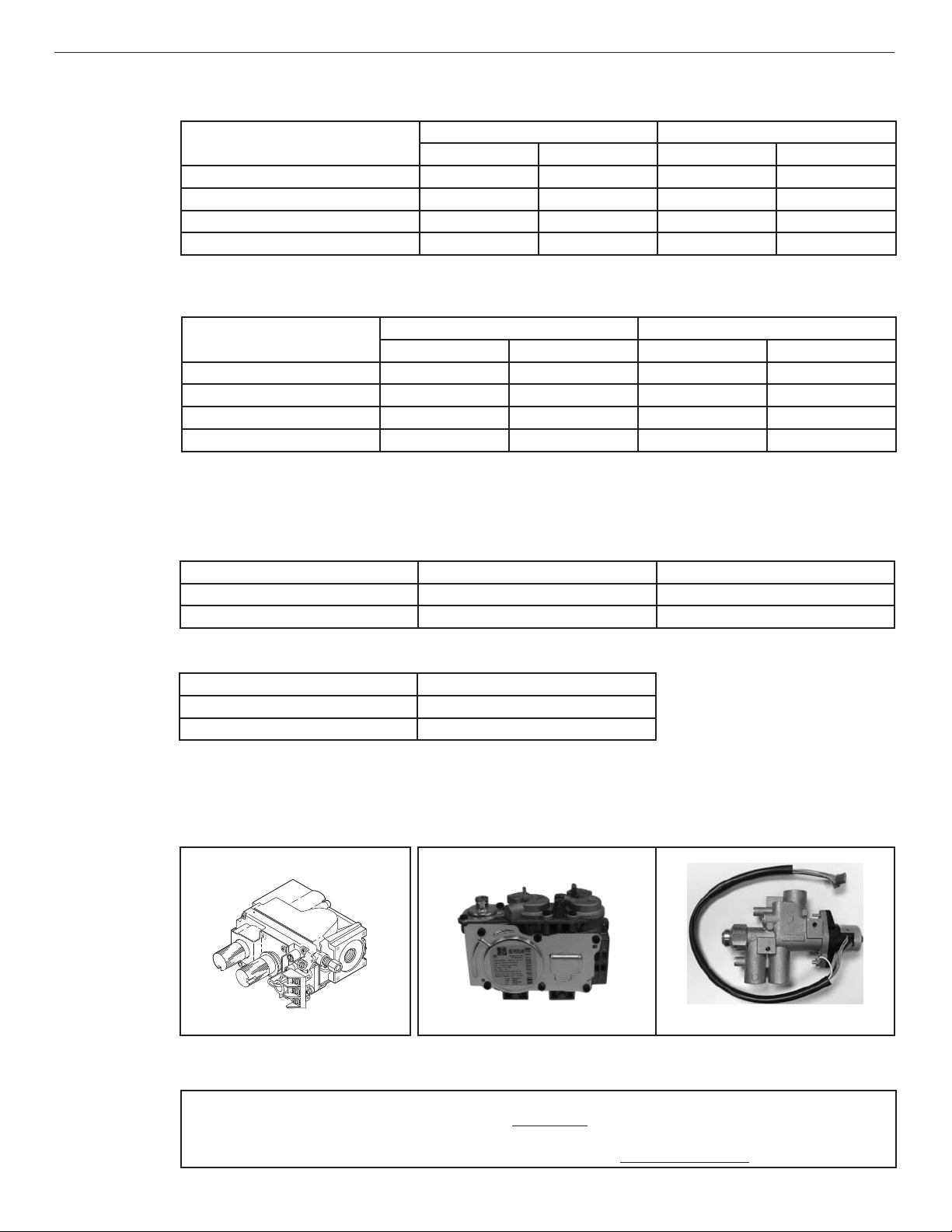
Test gauge connections are provided on the front of the millivolt and electronic gas control valve (identifi ed IN for the
inlet and OUT for the manifold side). The control valves have a 3/8” (10 mm) NPT thread inlet and outlet side of the
valve (Figures 1 and 2).
Figure 1 - Millivolt Gas Valve
Figure 2 - Electronic Gas Valves
SIT
Ecofl ow
Propane tanks are at pressures that will cause damage to valve components. Verify that the tanks have step down
regulators to reduce the pressure to safe levels.
The appliance and its appliance main gas valve must be disconnected from the gas supply piping system during
any pressure testing of that system at test pressures in excess of 1/2 psi (3.5 kPa).
The appliance must be isolated from the gas supply piping system by closing its equipment shutoff valve during
any pressure testing of the gas supply piping system at test pressures equal to or less than 1/2 psi (3.5 kPa).
9
Innovative Hearth Products
Gemini™ and GeminiCD Series Direct-Vent Gas Fireplaces
Orifi ce Sizes—Sea Level to High Altitude
These fi replaces are tested and approved for installation at elevations of 0–4500 ft (0–1372 m) above sea level
using the standard burner orifi ce sizes (Table 5). For elevations above 4500 ft, contact your gas supplier or qualifi ed
service technician.
Table 5 - Burner Orifi ce Sizes, Elevation 0–4500 ft ( 0–1372 m)
General Information
900285-01 08/2016
Model
33” Models #49 (0.073”)* #57 (0.043”)*
35” Models #48 (0.076”)* #56 (0.046”)*
40” Models #44 (0.086”)* #55 (0.052”)*
45” Models #43 (0.089”)* #54 (0.055”)*
* Standard size installed at factory
Deration
At elevations above 4500 ft, the amount of BTU fuel value delivered must be reduced by either:
• Using gas that has been derated by the gas company.
• Changing the burner orifi ce to a smaller size as regulated by the local authorities having jurisdiction and by the
(USA) National Fuel Gas Code NFPA 54/ANSI Z223.1—latest edition or, in Canada, the CAN/CGA-B149.1 codes—
latest edition.
NOTE: Flame breadth, height and width will diminish 4% for every 1,000 ft of altitude.
IN CANADA—CAN/CGA-2.17-M91 (HIGH ALTITUDE):
THE CONVERSION SHALL BE CARRIED OUT BY A MANUFACTURER’S AUTHORIZED REPRESENTATIVE,
IN ACCORDANCE WITH THE REQUIREMENTS OF THE MANUFACTURER, PROVINCIAL OR TERRITORIAL
AUTHORITIES HAVING JURISDICTION AND IN ACCORDANCE WITH THE REQUIREMENTS OF THE CAN/
CGA-B149.1 OR CAN/CGA-B149.2 INSTALLATION CODES.
COMMONWEALTH OF MASSACHUSETTS REQUIREMENTS
Natural Gas
drill size
Propane
drill size
These appliances are approved for installation in the US state of Massachusetts if the following additional
requirements are met:
• Install this appliance in accordance with Massachusetts Rules and Regulations 248 C.M.R. Sections 4.00
through 8.00.
• Installation and repair must be done by a plumber or gas fi tter licensed in the Commonwealth of Massachusetts.
• The fl exible gas line connector used shall not exceed 36 inches (92 centimeters) in length.
• The individual manual shut-off must be a T-handle type valve.
Massachusetts Horizontal Vent Requirements
In the Commonwealth of Massachusetts, horizontal terminations installed less than seven (7) feet above the fi nished
grade must comply with the following additional requirements:
• A hard wired carbon monoxide detector with an alarm and battery back-up must be installed on the fl oor level
where the gas fi replace is installed. The carbon monoxide detector must comply with NFPA 720, be ANSI/UL
2034 listed and be ISA certifi ed.
• A metal or plastic identifi cation plate must be permanently mounted to the exterior of the building at a minimum height
of eight (8) feet above grade and be directly in line with the horizontal termination. The sign must read, in print size no
less than one-half (1/2) inch in size, GAS VENT DIRECTLY BELOW. KEEP CLEAR OF ALL OBSTRUCTIONS.
COLD CLIMATE INSULATION
For cold climate installations, seal all cracks around your fi replace with noncombustible material and wherever cold
air could enter the room. It is especially important to insulate outside chase cavity between studs and under fl oor on
which fi replace rests, if fl oor is above ground level. Gas line holes and other openings should be caulked or stuffed
with unfaced fi berglass insulation.
NOTE: Do not use loose, or blown-in insulation in the cavity surrounding the fi replace.
If the fi replace is being installed on a cement slab in cold climates, a sheet of plywood or other raised platform can
be placed underneath to prevent conduction of cold transferring to the fi replace and into the room. It also helps to
seal inside surfaces and tape for maximum air tightness and caulk fi restops.
10
Innovative Hearth Products
Gemini™ and GeminiCD Series Direct-Vent Gas Fireplaces
MANUFACTURED HOME REQUIREMENTS
This appliance may be installed in an aftermarket, permanently located, manufactured home (USA only) or mobile
home, where not prohibited by local codes.
Cet appareil peut être installé dans une maison préfabriquée (mobile) déjà installée à demeure si les règlements
locaux le permettent.
This appliance is only for use with the type of gas indicated on the rating plate. This appliance is not convertible for
use with other gases, unless a certifi ed kit is used.
Cet appareil doit être utilisé uniquement avec le type de gaz indiqué sur la plaque signalétique. Cet appareil ne
peut être converti à d’autres gaz, sauf si une trousse de conversion est utilisée.
Ensure that the cross members are not cut or weakened during installation. The structural
integrity of the manufactured home fl oor, wall, and ceiling / roof must be maintained.
This appliance must be grounded to the chassis of the manufactured home in accordance
with local codes or in the absence of local codes, with the National Electrical Code ANSI /
NFPA 70—latest edition or the Canadian Electrical Code CSA C22.1—latest edition.
General Information
900285-01 08/2016
CAUTION
CAUTION
LOCATION
In selecting the location, the aesthetic and functional use of the fi replace are primary concerns. However, vent
system routing to the exterior and access to the fuel supply are also important.
Due to high temperatures, the fi replace should be located out of traffi c and away from furniture and draperies.
En raison des températures élevées, l’appareil devrait être installé dans un endroit où il y a peu de
circulation et loin du mobilier et des tentures.
The location should also be free of electrical, plumbing or other heating/air conditioning ducting.
These direct-vent fi replaces are uniquely suited for installations requiring a utility shelf positioned directly above the
fi replace. Utility shelves like these are commonly used for locating television sets and decorative plants.
Be aware that this is a heat producing fi replace. Objects placed above the unit are exposed to elevated temperatures.
Do not insulate the space between the fi replace and the area above it.
The minimum height from the base of the fi replace to the underside of combustible materials used to construct a
utility shelf in this fashion is shown in Table 9.
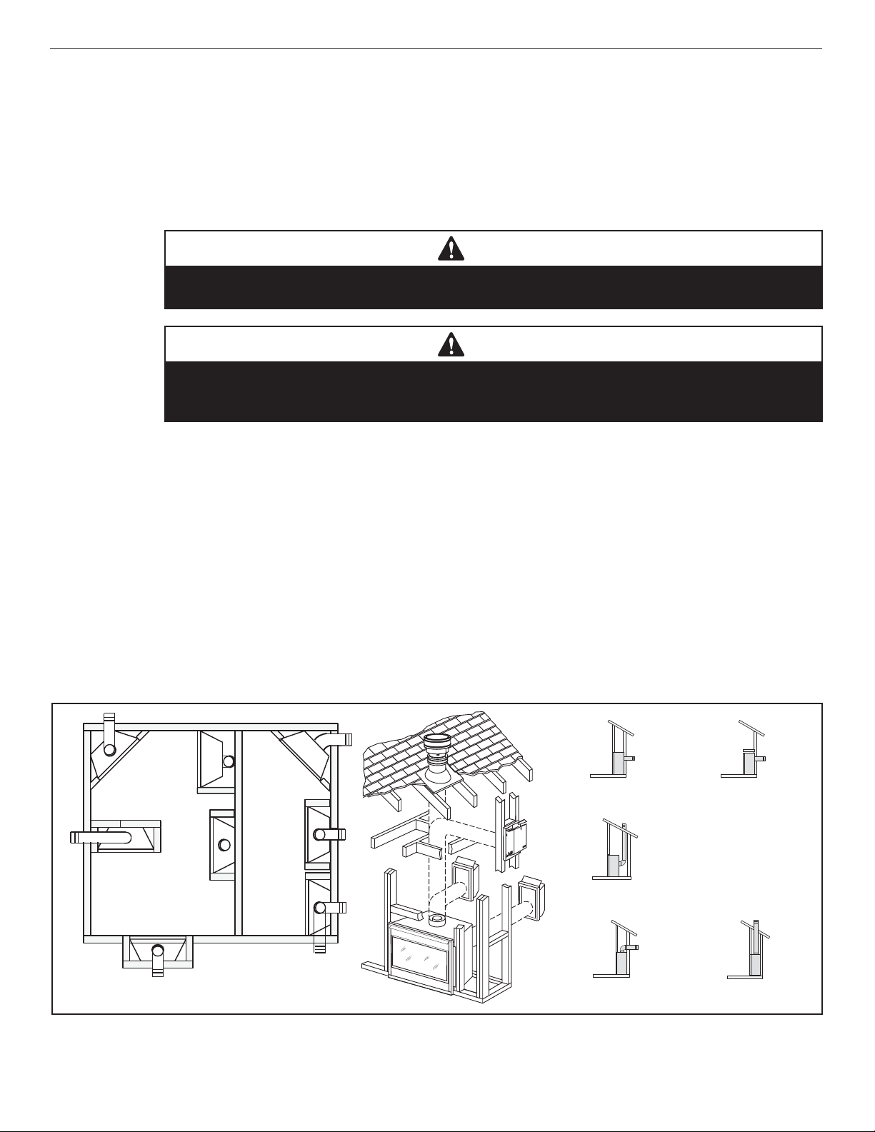
Figure 3 - Typical Locations and Venting
Top Vent
Top Vent
Rear Vent
Top Vent
Rear Vent
Horizontal Vent
(Rear Vent with chase)
Horizontal Vent
(Rear Vent without chase)
Recessed
Installation
Top Vent
Top Vent Top Vent
Vertical Vent
(Rear Vent)
Horizontal Vent
(Top Vent)
Vertical Vent
(Top Vent)
11
Innovative Hearth Products
Gemini™ and GeminiCD Series Direct-Vent Gas Fireplaces
VENT TERMINATION CLEARANCES
These instructions should be used as a guideline and do not supersede local codes in any way. Install venting
according to local codes, these instructions, the current National Fuel Gas Code (ANSI Z223.1/NFPA 54) in the USA or
the current standards of CAN/CGA-B149.1 in Canada.
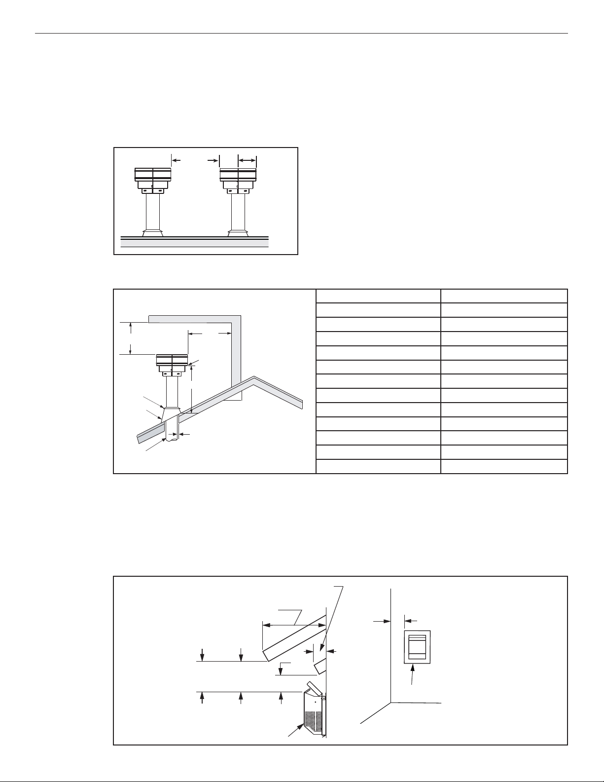
Vertical Vent Termination Clearances
Terminate multiple vent terminations according to the installation codes listed above and Figure 4.
Figure 4 - Multiple Terminations
General Information
900285-01 08/2016
12”
(305 mm)
minimum
6”
(153 mm)
Terminate single vent caps relative to building components according to Table 6 and Figure 4.
Table 6 - Termination Heights for Vents above Flat or Sloped Roofs (NFPA 54 / ANSI Z223.1)—Gas Vent Rule
TERMINATION HEIGHTS FOR VENTS ABOVE
Horizontal overhang
2 ft minimum
termination
Storm collar
Flashing
Concentric
vent pipe
FLAT OR SLOPED ROOFS
Vent
2 ft
minimum
Lowest
discharge
opening
H*
1” (26 mm) minimum
clearance to combustibles
*H = minimum height from roof to
lowest discharge opening of vent
Vertical
wall
X
12
Roof pitch is X/12
Roof Pitch Termination Height *
Flat to 6/12 1.0 ft (0.3 m)
6/12 to 7/12 1.25 ft (0.38 m)
7/12 to 8/12 1.5 ft (0.46 m)
8/12 to 9/12 2.0 ft (0.61 m)
9/12 to 10/12 2.5 ft (0.76 m)
10/12 to 11/12 3.25 ft (0.99 m)
11/12 to 12/12 4.0 ft (1.22 m)
12/12 to 14/12 5.0 ft (1.52 m)
14/12 to 16/12 6.0 ft (1.83 m)
16/12 to 18/12 7.0 ft (2.13 m)
18/12 to 20/12 7.5 ft (2.29 m)
20/12 to 21/12 8.0 ft (2.44 m)
Horizontal Vent Termination Clearances
The horizontal vent termination must have a minimum of 6” (152 mm) clearance to any overhead combustible
projection of 2-1/2” (64 mm) or less (Figure 5). For projections exceeding 2-1/2” (64 mm) (Figure 5). For additional
vent location restrictions refer to Table 7.
All horizontal terminations may be located as close as 6” (152mm) to any (non-combustible and combustible)
exterior sidewall. This distance may be decreased to 2” (51mm) for noncombustible exterior sidewalls with all
approved terminations (Pages 48-49).
Figure 5 - Horizontal Vent Termination Clearances
12
Combustible projection
2-1/2” or less in length
Combustible projection
greater than 2-1/2” in length
Ventilated
soffi t - 18”
(457 mm)
Unventilated
soffi t - 12”
(305 mm)
Termination kit
6”
(152)
6”
*
Termination kit**
* 10” to center of termination for H1968
** Use 6-1/2” from center of termination for
all horizontal terminations applicable.
Innovative Hearth Products
Gemini™ and GeminiCD Series Direct-Vent Gas Fireplaces
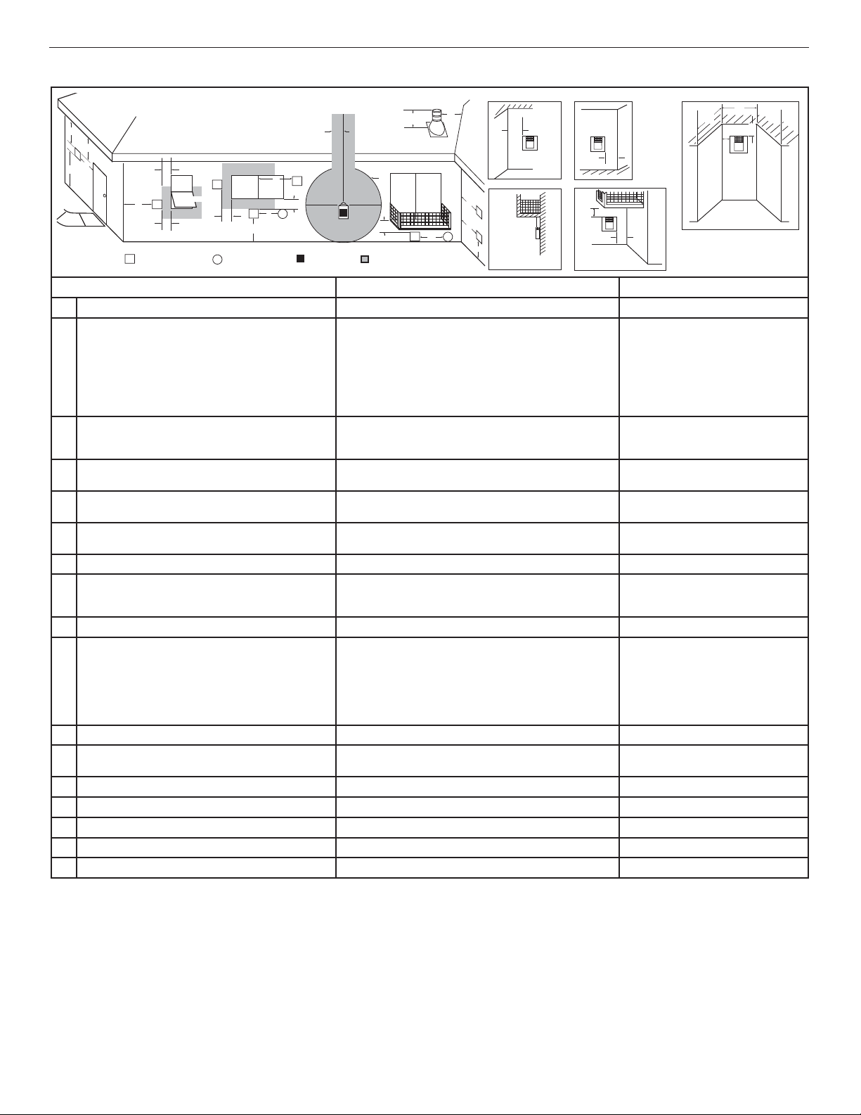
Table 7 - Horizontal vent termination clearances for buildings with combustible and noncumbustible exteriors
Inside Corner
D
E
V
B
L
C
F
V
B
TERMINATION CAP
V
Fixed
Closed
Openable
V
Openable
V
B
A
AIR SUPPLY INLET
X
Fixed
Closed
J
B
V
B
X
G
GAS METER RESTRICTED AREA
See Table 6
H
I
G
(TERMINATION PROHIBITED)
G
V
Balcony with No Side WallVBalcony with Perpendicular Side Wall
G
V
M
V
G
V
X
K
A
M
V
U.S. Installation ** Canadian Installation *
Clearance above grade, veranda, porch, desk, or balcony 12” (300 mm) ** 12” (300 mm) *
A
Clearance to window or door that may be opened 6” (150 mm)
B
for fi replaces < 10,000 Btu/h (3 kW),
9” (230 mm)
for fi replaces > 10,000 Btu/h (3 kW), and < 50,000 Btu/h (15
kW),
12” (300 mm)
for fi replaces > 50,000 Btu/h (15 kW) **
Clearance to permanently closed window 9” (229 mm)
C
Vertical clearance to ventilated soffi t located above the
D
termination within a horizontal distance of 18” (458 mm)
Clearance to unventilated soffi t 12” (305 mm) 12” (305 mm)
E
recommended to prevent window condensation
18” (458 mm) 18” (458 mm)
Outside Corner Recessed Location
V
F
M
6” (150 mm)
for fi replaces < 10,000 Btu/h (3 kW),
12” (300 mm)
for fi replaces > 10,000 Btu/h (3 kW)
12” (305 mm)
recommended to prevent window
condensation
General Information
900285-01 08/2016
P
N
Q
O
V
Clearance to outside corner 5” (127 mm)
F
Clearance to inside corner 6” (152 mm) minimum 6” (152 mm) minimum
G
Clearance to each inside of center line extended above
H
meter / regulator assembly
minimum
36” (910 mm)
within a height of 15 ft above the meter / regulator assembly **
5” (127 mm)
minimum
36” (910 mm)
within a height of 15 ft above the meter /
regulator assembly *
Clearance to service regulator vent outlet 36” (910 mm)** 36” (910 mm)*
I
Clearance to nonmechanical air supply inlet to building or
J
the combustion air inlet to any other fi replace
6” (150 mm)
for fi replaces < 10,000 Btu/h (3 kW),
9” (230 mm)
for fi replaces > 10,000 Btu/h (3 kW) and < 50,000 Btu/h (15 kW),
6” (150 mm)
for fi replaces < 10,000 Btu/h (3 kW),
12” (300 mm)
for fi replaces > 10,000 Btu/h (3 kW)
12” (300 mm)
for fi replaces > 50,000 Btu/h (15 kW)**
Clearance to a mechanical air supply inlet 36” (910 mm) above if within 10 ft (3 m) horizontally ** 72” (1830 mm) *
K
Clearance above paved sidewalk or paved driveway located
L
on public property
Clearance under veranda, porch, deck or balcony 12” (300 mm) *‡ 12” (300 mm) *‡
M
Depth of alcove (maximum) 72” (1830 mm) ** 72” (1830 mm) *
N
Clearance to termination (alcove) 6” (15.2 mm) ** 6” (15.2 mm)*
O
Width of alcove (minimum) 36” (910 mm) ** 36” (910 mm) *
P
Clearance to combustible above (alcove) 18” (457 mm) ** 18” (457 mm) *
Q
*
In accordance with the current CAN/CGA-B149.1 National Gas And Propane Installation Code
**
In accordance with the current ANSI Z223.1/NFPA 54 National Fuel Gas Codes
‡
A vent shall not terminate directly above a sidewalk or paved driveway which is located between two single family dwellings and serves both dwellings
*‡
Only permitted if veranda, porch, deck, or balcony is fully-open on a minimum two sides beneath the fl oor
84” (2130 mm) ‡ 84” (2130 mm) ‡
13
Innovative Hearth Products
Gemini™ and GeminiCD Series Direct-Vent Gas Fireplaces
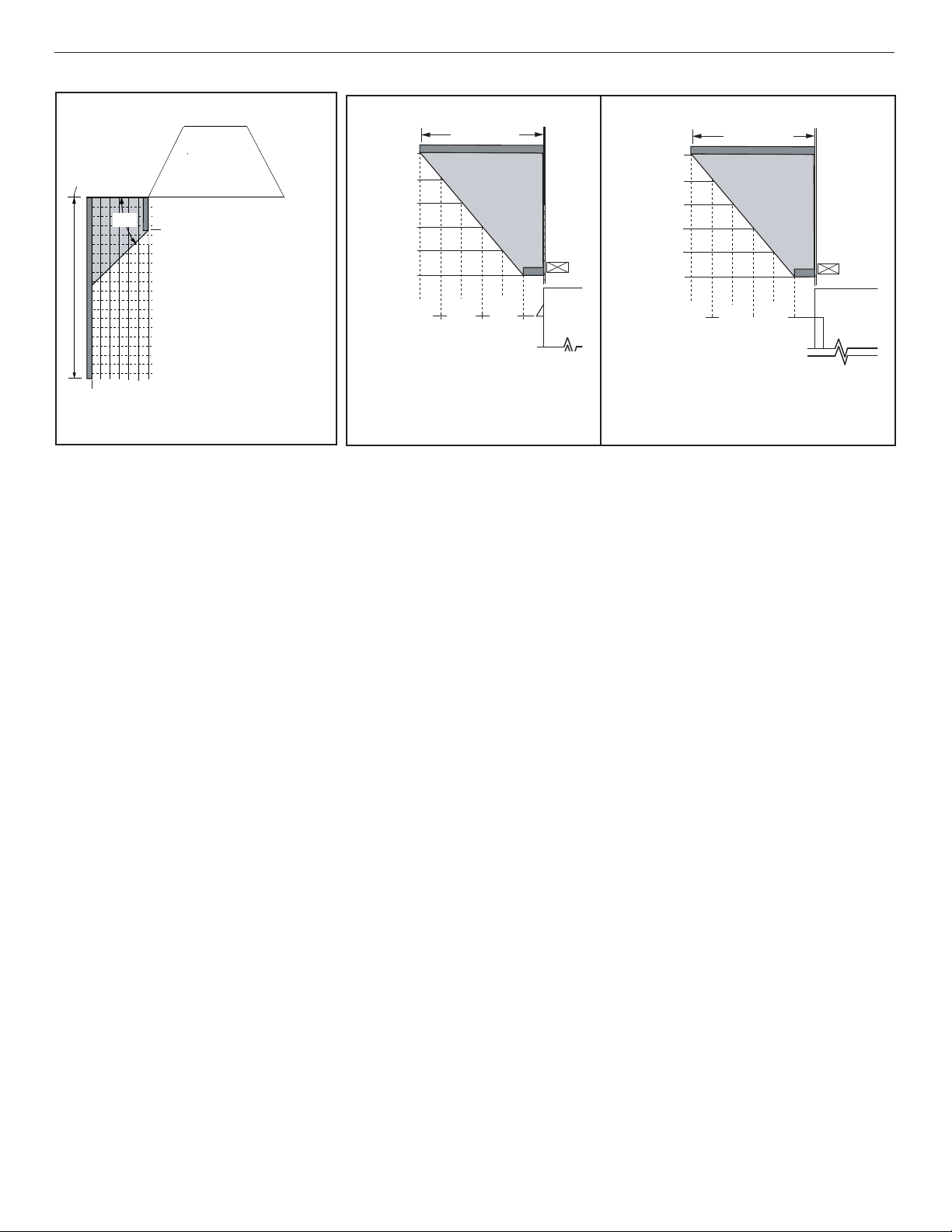
MINIMUM CLEARANCES TO COMBUSTIBLES
Fireplace And Vent Clearances
The fi replace is approved with zero clearance to combustible materials on all sides (Table 8), with the following
exception: The unit may not be recessed (allowance made for mantel legs / side trim in (Figure 6). When the unit is
installed with one side fl ush with a wall, the wall on the other side of the unit must not extend beyond the front edge
of the unit (Figure 6).
Table 8 - Minimum Clearances *
From Bottom of Unit to Ceiling
Front Service Clearance—
clearance immediately in front of viewing area(s)
Back
Sides
Top Standoffs 0” (0 mm) to top standoffs
Floor
Vent
1” (26mm) to wrapper
0” (0 mm) to Spacers
1/2” (13 mm) to wrapper
0” (0 mm) to Spacers **
0” (0 mm)
64” (1626 mm)
3” (77 mm)—Top *
1” (26 mm)—Sides and Bottom
36” (914 mm)
General Information
900285-01 08/2016
The fi replace must be mounted on a fully supported base extending the full width and depth of the unit. The fi replace
may be located on or near conventional construction materials. However, if installed on combustible materials, such
as carpeting, vinyl tile or other combustible material other than wood fl ooring, the appliance shall be installed on a
metal or wood panel extending the full width and depth of the appliance.
Hearth Extension
A hearth extension is not required with this fi replace. If a hearth extension is used, do not block the lower control
compartment door. Any hearth extension used is for appearance only and does not have to conform to standard
hearth extension installation requirements.
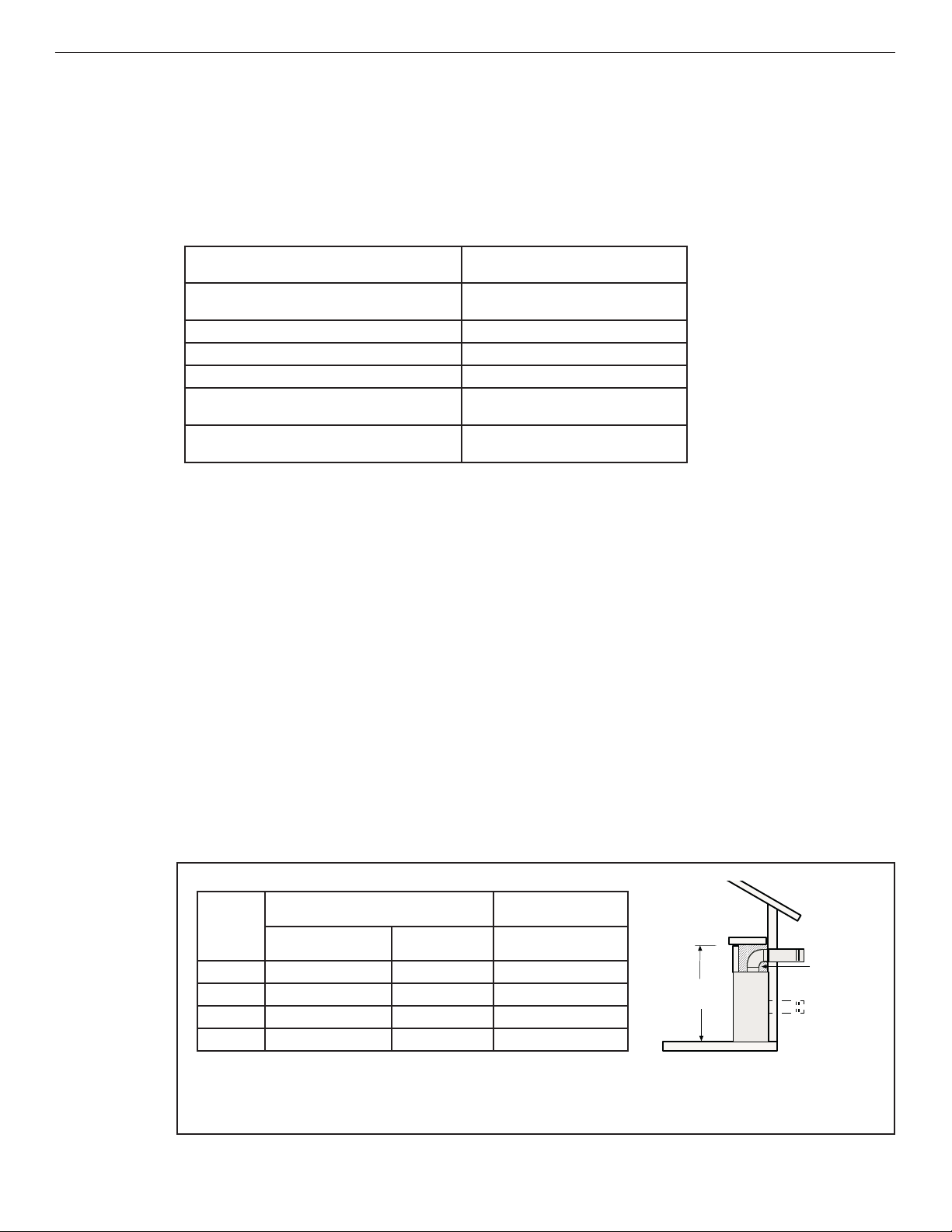
Shelf Height
To provide for the lowest possible shelf surface, use the rear vent model. For top vent models, the venting attached
to the top vent should be routed in a way to minimize obstructions to the space above the fi replace. Do not insulate
the space between the fi replace and the area above it (Table 9). The minimum height from the base of the fi replace
to the underside of combustible materials used to construct a utility shelf in this fashion is shown in Table 9.
Table 9 - Combustible Shelf Height—Top Vent
* 3” (77 mm) above any horizontal/inclined vent component.
** See Page 21 for clearance requirements to the nailing fl ange located at each side of the unit and any screw heads adjacent to it.
Top Vent with one 90° Elbow
Model
Secure Vent
33” Models 44” (1118 mm)* 46” (1168 mm)* 39” (990 mm)**
35” Models 47” (1194 mm)* 49” (1245 mm)* 41” (1042 mm)**
40” Models 52” (1321 mm)* 54” (1372 mm)* 46” (1169 mm)**
45” Models 52” (1321 mm)* 54” (1372 mm)* 46” (1169 mm)**
®
Secure Flex®
(fl ex elbow)
Alternative Rear Vent
applications
Secure Vent
®
Shelf Height
(see table)
No combustibles or
insulation
in the
shaded area
between the
appliance
and the
shelf above
it.
14
* Includes 3” clearance to combustibles (required above vent components)
** In alternative, Rear Vent applications, Top Vent will be sealed as detailed in the
Installation and Operation manual.
Innovative Hearth Products
Gemini™ and GeminiCD Series Direct-Vent Gas Fireplaces
General Information
900285-01 08/2016
Figure 6 - Combustible Side Clearances
At 6” minimum
side wall
At 6 in. minimum
clearance, a
side wall clearance,
combustible wall
a combustible wall
can project to any
can project to any
length.
length.
o
o
45
45
Top View of
Top View of
3 1/2 in.
3-1/2”
(89 mm)
(89 mm)*
Fireplace
Fireplace
Combustible materials
Combustible Materials
allowed in shaded area
Allowed In Shaded Area
“Safe Zone”.
“Safe Zone”
Combustible Walls
Combustible walls
shown in dark gray
shown in dark gray
Combustible mantel legs may
Combustible mantel
project beyond either side
legs may project
of the fireplace opening
beyond either side of
as long as they are kept
the fi replace opening
within the shaded area
as long as they are kept
illustrated here.
within the shaded area
illustrated here.
6”
(152 mm)
* 6” (152 mm) in 35” and 40” Contemporary units
Wall Finishes / Surrounds / Mantels
NOTE: Combustible wall fi nish materials and/or surround materials must not be allowed to encroach the area defi ned
by the fi replace front face (black sheet metal). Never allow combustible materials to be positioned in front of or
overlapping the fi replace face (Figure 40).
Non-combustible materials, such as surrounds and other fi replace trim, may be installed on the fi replace face, but they
must not cover any portion of the removable glass panel or control compartment.
Vertical installation clearances to combustible mantels vary according to the depth of the mantel (Figure 7). Mantels
constructed of non-combustible materials may be installed at any height above the fi replace opening. However, do
not allow anything to hang below the fi replace hood.
Minimum clearance requirements include any projections such as shelves, window sills, mantels, etc. above the
fi replace.
Figure 7 - Mantel Height
12
(305)
Mantel depth
(203)
10
(254)
8
6
(152)
20 (508)
18 (457)
16 (406)
14 (356)
12 (305)
10 (254)
in. (mm)
Traditional
4
(102)
2
(51)
Hood
Fireplace
25 (635)
23 (584)
21 (533)
19 (483)
17 (432)
15 (381)
12
(305)
10
(254)
Contemporary
Mantel depth
8
(102)
6
(203)
(152)
4
2
(51)
Fireplace
Opening
Fireplace
NOTE: To avoid heat-related fi nish damage, we recommend the use of high temperature paint (rated 175° F or higher) on
the underside of the mantel.
INSTALLATION PREPARATION
The fi replace is shipped with all gas controls and components installed and pre-wired. Before installing the fi replace,
follow these steps:
1. Remove the shipping carton, and retain the front of the carton (used to protect the fi replace during construction).
2. Remove the shipping pad, exposing the front glass door.
3. Remove the glass door (Page 58).
NOTE: Place the glass door on the shipping carton to protect its surface.
15

Innovative Hearth Products
Gemini™ and GeminiCD Series Direct-Vent Gas Fireplaces
INSTALLATION SEQUENCE
The typical sequence of installation is outlined below; however, each installation is unique and may result in
variations to the steps described.
See the pages referenced in the following steps for detailed instructions.
Framing
1. Construct the Fireplace Framing (Page 16).
2. Prepare the Fireplace Top Spacers (Page 18).
3. Route the Gas Supply Line to the Fireplace (Page 18).
4. Determining Vent Setup in the Combination Venting Unit (Page 19)
5. Installing Metal, Non-Combustible Front Standoff (Page 19)
6. Rough in the Electrical Supply, if Needed (Page 20).
7. Install the [Optional] Blower Kit before Installation in the Framing (Page 20).
Venting
8. Place the Fireplace in the Framing and Secure (Page 21).
9. Select a Horizontal or Vertical Vent System (Page 21).
10. Install the Vent Restrictor (if necessary) (Page 22).
11. Install the Vent System (Page 25).
Electrical Connection
12. Complete the Field Wiring (Page 37).
13. Install the [Optional] Blower Kit after Installation in the Framing (Page 39).
Gas Connection
14. Connect the Gas Line (Page 40).
15. Verify Proper Fireplace Operation (Page 41).
Finishing
16. Optional: Install the Firebox Liners (Page 42).
17. Install the Logs, Volcanic Stone, and Glowing Embers or Glass Media
18. Install the Glass Door (Page 42).
19. Adjust the Air Shutter to Ensure Proper Flame Appearance (Page 42).
20. Install the Hood in Traditional Fireplaces (Page 43).
21. Reinstall the Included Barrier (Page 44).
22. Install the Finishing Materials and Facade in Contemporary Fireplaces (Page 44).
23. Attach the Safety-in-Operation Warning Labels (Page 47).
24. Installing Batteries for Backup and Wall Switch (Page 44).
Installation
900285-01 08/2016
(Page 42).
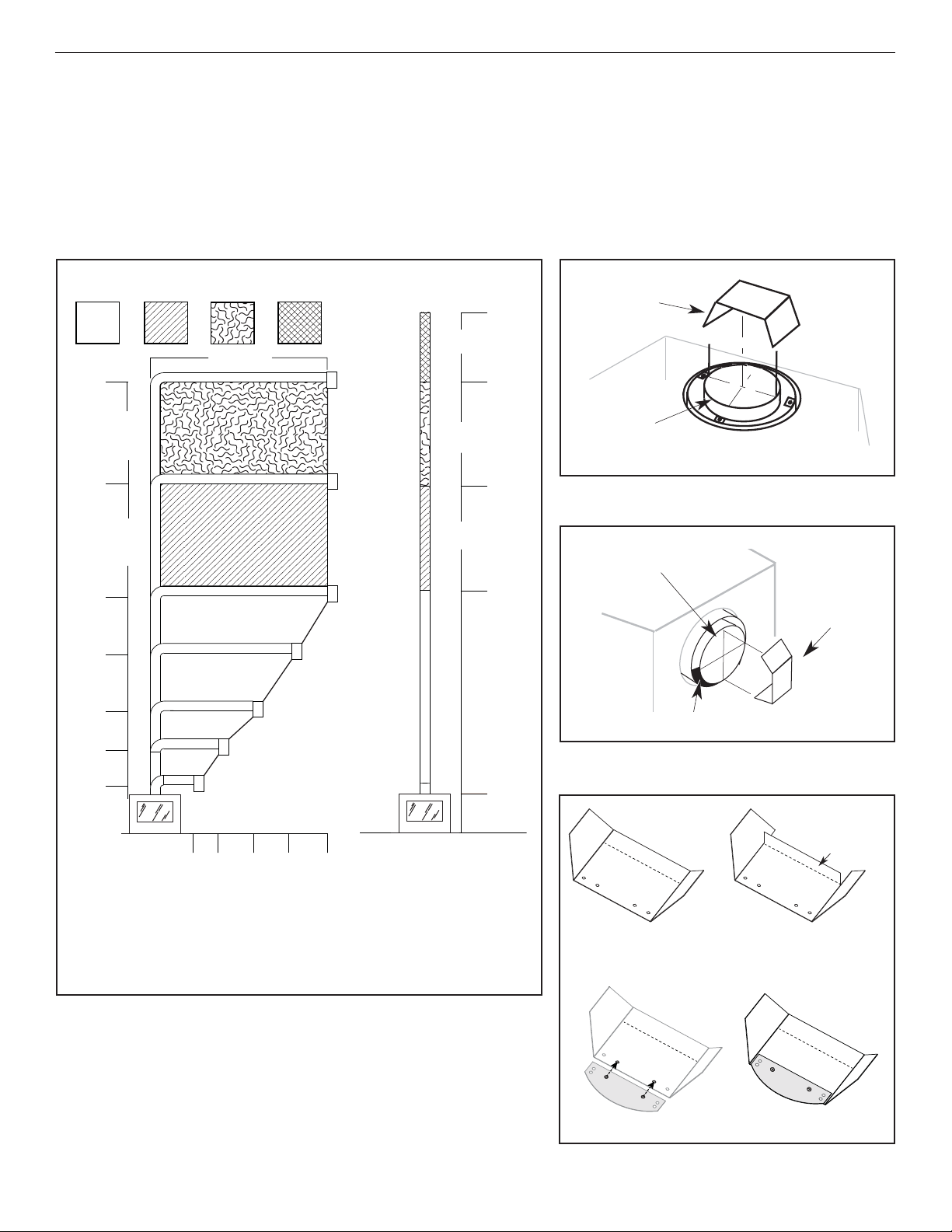
1. Construct the Fireplace Framing
1. Frame the fi replace as illustrated in Table 10. For corner framing installations, use Table 11. All framing details
must allow for a minimum clearance to combustible framing members as shown in Table 8.
2. If the fi replace is to be elevated above fl oor level, a solid continuous platform must be constructed below the fi replace.
NOTE: Headers may be in direct contact with the fi replace top standoff spacers when they are bent up vertically,
maintaining the 4” clearance to the fi replace top, but must not be supported by them or notched to fi t around them.
All construction above the fi replace must be self-supporting. DO NOT use the fi replace for structural support.
NOTE: For contemporary models, leave a minimum of 6” clearance to any side wall for proper facade installation and
fi t .
16
Innovative Hearth Products
Gemini™ and GeminiCD Series Direct-Vent Gas Fireplaces
Installation
900285-01 08/2016
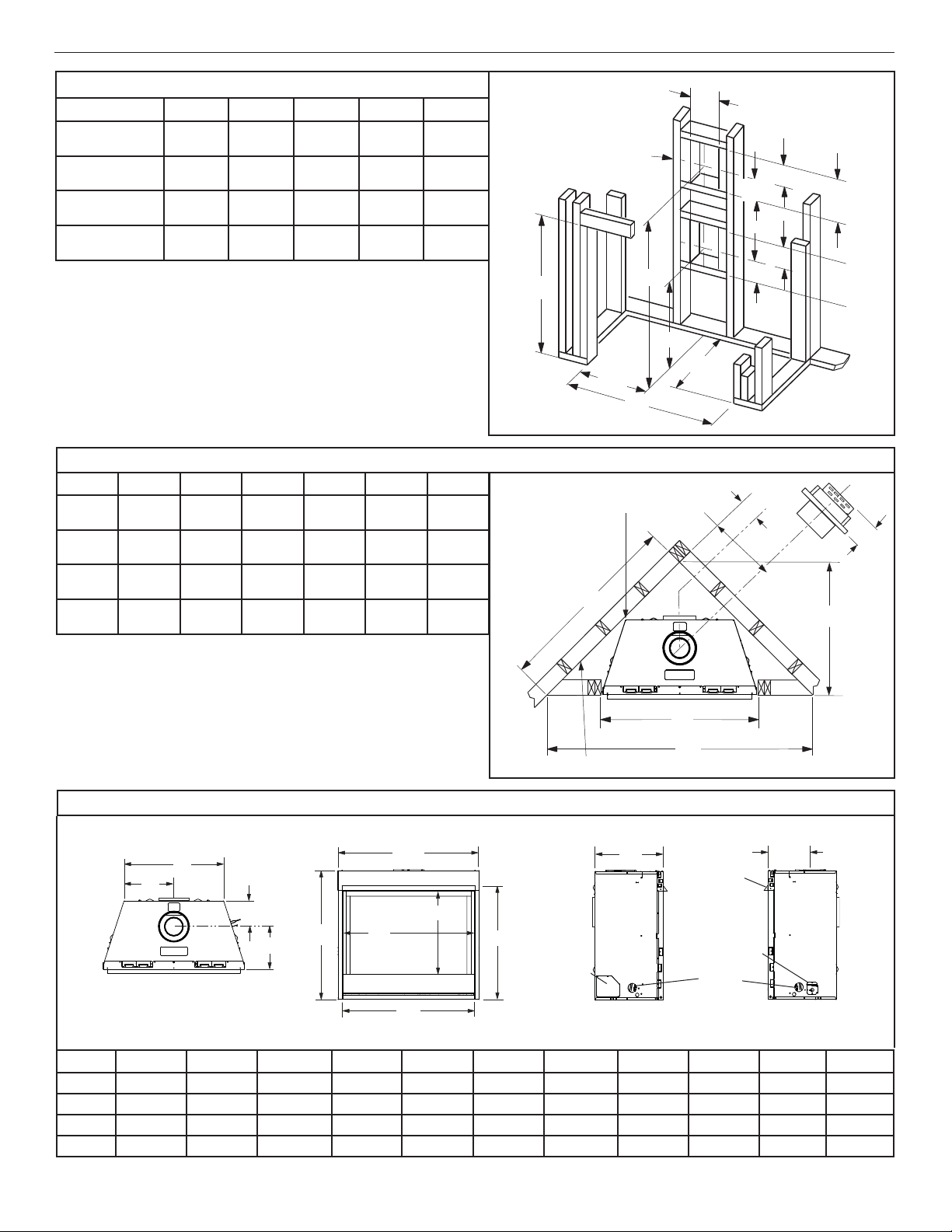
Table 10 - Fireplace Framing Specifi cations
Model A * B C D E
33” Models
35” Models
40” Models
45” Models
33-3/4
(857)
35-3/8
(899)
40-3/8
(1026)
45-3/8
(1153)
34-1/4
(845)
36-1/4
(895)
41-1/4
(1048)
41-1/4
(1048)
36-7/8
(930)
38-3/4
(984)
43-3/4
(1111)
43-3/4
(1111)
C = Minimum height of top vent installations
14-1/2
(368)
18
(447)
18
(447)
18
(447 )
19-5/8
(499)
23-3/8
(594)
28-1/4
(717)
28-1/4
(717)
NOTE: Dimension “D” is the
required framing depth when
the fi nish material (drywall)
thickness is 1/2” (13mm).
Vent Framing—Top Vent
with One 90° Elbow
B
E = Minimum height of rear vent installations
* Minimum opening size; additional 1/8” per side is recommended.
NOTE: Framing specifi cations do NOT apply for fl exible venting.
When using fl exible venting, refer to the kit requirements for framing
specifi cations.
Inches
(millimeters)
Table 11 - Fireplace Framing Specifi cations—Corner Installation with Horizontal Termination
Model A B C D E F
33”
35”
40”
45”
33-3/4
(857)
35-3/8
(899)
40-3/8
(1025)
45-3/8
(1153)
51-1/4
(1302)
59-1/2
(1511)
63-7/8
(1622)
70-3/8
(1788)
36-1/4
(921)
42-1/8
(1070)
45-3/8
(1153)
49-3/4
(1264)
25-5/8
(651)
30-1/4
(768)
33-1/4
(845)
35-1/4
(895)
12-1/8
(308)
14-1/4
(362)
15-7/8
(403)
17-1/2
(445)
5-1/2
(140)
6-5/8
(168)
8-1/2
(216)
10-1/4
(260)
C
1/2 A
Framing
10-1/2
construction to be
(267)
2 x 4, or larger.
7 (178)
5-1/8
(130)
C
E
D
A
E
F
12-1/8
(308)
D
7
(178)
A
B
Back wall of chase/enclosure (including fi nishing materials)
Inches
(millimeters)
Table 12 - Fireplace Specifi cations
NOTE: When fi nishing the area around the hood, 5/8” clearance above hood is required for hood installation.
F
G
I
K
Top View Front View
Model A B C D (door) E F G H I J K
33” Models 30-1/8 (765) 26-1/4 (667) 18-3/8 (467) 30-1/2 (775) 33-5/8 (854) 21-7/8 (556) 11 (279) 31 (787) 5-3/4 (146) 14 (356) 8-1/2 (207)
35” Models 32-1/8 (816) 28-3/4 (730) 22-1/4 (565) 32-3/8 (822) 35-1/4 (895) 25 (635) 12-1/2 (317) 32-7/8 (835) 6-7/8 (175) 17 (432) 10-1/8 (257)
40” Models 37-1/8 (943) 33-1/4 (845) 27-1/4 (692) 37-3/8 (949) 40-1/4 (1022) 30 (762) 15 (381) 37-7/8 (962) 6-7/8 (175) 17 (432) 10-1/8 (257)
45”Models 37-1/8 (943) 33-1/4 (845) 27-1/4 (692) 42-3/8 (1076) 45-1/4 (1149) 35 (889) 17-1/2 (445) 42-7/8 (1089) 6-7/8 (175) 17 (432) 10-1/8 (257)
A
E
C
D
H
B
Blower
access panel
JK
Hood
Junction
box access
Gas line
access
Left Side View Right Side View
17
Innovative Hearth Products
Gemini™ and GeminiCD Series Direct-Vent Gas Fireplaces
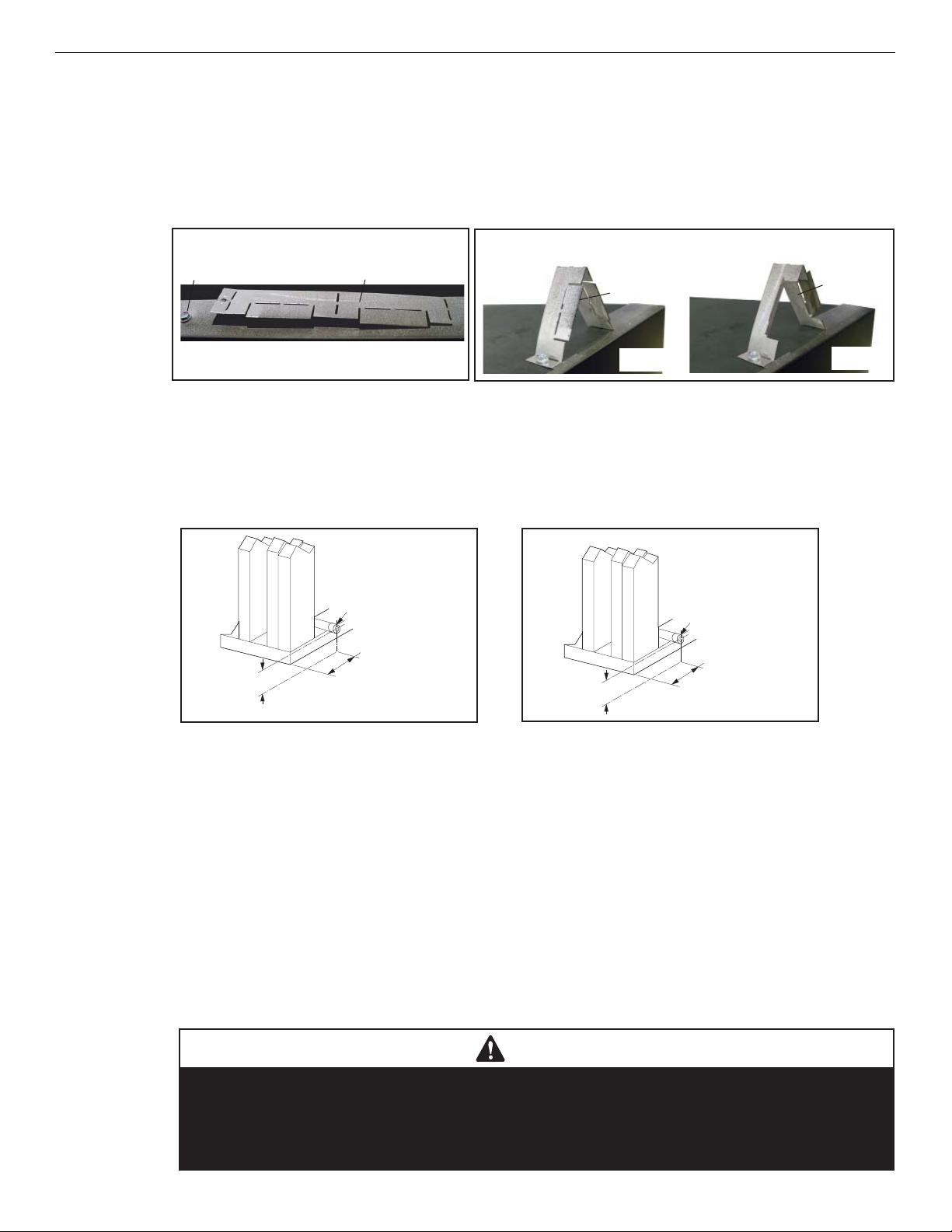
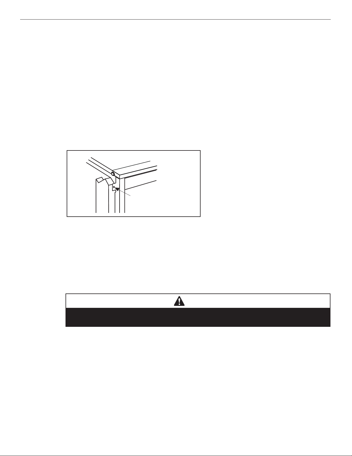
2.
Prepare the Fireplace Top Spacers
1. The two (2) 4” standoff spacers on top of the fi replace cabinet are shipped fl at. Remove the screw adjacent to
the detached end (Figure 8).
2. Bend the standoffs as shown (Figure 9):
3. Align the hole in the standoff with the hole in the fi replace top, and secure with the screw that was removed in
Step 1 (Figure 9).
Figure 8 - Unassembled standoff
Installation
900285-01 08/2016
Figure 9 - Assembled standoffs
Positioned fl at as shipped from the factory
Screw
Fireplace Front
Top Standoff
3. Route the Gas Supply Line to the Fireplace
1. Route a 1/2” (13 mm) gas line to the left side of the fi replace (Figure 10).
NOTE: Gas lines must be routed, assembled, and made of materials that are in strict accordance with local codes and
regulations. All fi replaces are factory-equipped with a fl exible gas line connector and a 1/2” shutoff valve (Page 40).
Figure 10 - Routing the gas line - 35”, 40”,
45” Models
Left side front corner of
fi replace framing
Pipe coupling
(recommended)
7-5/8”
(195 mm)
3”
(77 mm)
Confi guration for 1/2" fi nish materials
Top Standoff
Fireplace
Front
Confi guration for 5/8" fi nish materials
Figure10a - Routing the Gas Line - 33” Model
Left side front corner of
fi replace framing
Pipe coupling
(recommended)
5-1/4”
(140 mm)
3”
(77 mm)
Top Standoff
Fireplace
Front
18
Proper Sizing of Gas Line
Properly size and route the gas supply line from the supply regulator to the area where the appliance is to be installed
per requirements outlined in the National Fuel Gas Code, NFPA 54—latest edition (USA) or CAN/CGA-B149.1—latest
edition (Canada).
The gas supply line should not be connected to the appliance until step 14. Connect the Gas Line (Page 40).
NOTE:
• All fi replaces are factory-equipped with a fl exible gas line connector and 1/2” shutoff valve (Figure 35).
• See Massachusetts Horizontal Vent Requirements for additional requirements for installations in the state of
Massachusetts in the USA.
• A pipe joint compound rated for gas should be used on the threaded joints. Ensure propane-resistant
compounds are used in propane applications. Be very careful that the pipe compound does not get inside the
pipe.
• A sediment trap in the supply line as close as possible to the fi replace is recommended.
• Check with the local building offi cial for local code requirements (e.g., Are below grade penetrations of the gas
line allowed?, etc).
CAUTION
If propane is used, be aware that with a tank that is too small (i.e., under 100 lbs, if this
is the only gas appliance in the dwelling—see NPFA 58), there may be a loss of pressure.
This can result in insuffi cient fuel delivery that can cause sooting, delayed ignition, or other
malfunctions. Any damage resulting from an improper installation is not covered by the
limited warranty.
Innovative Hearth Products
Gemini™ and GeminiCD Series Direct-Vent Gas Fireplaces
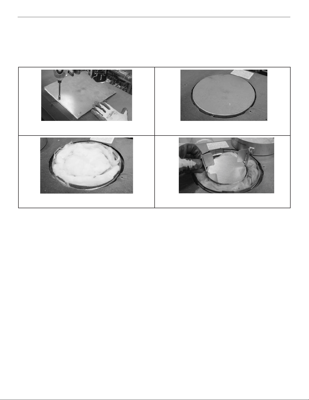
Determining Vent Setup in the Combination Venting Unit
4.
900285-01 08/2016
Combination venting units are shipped with rear venting setup nearly ready for install. If this is the type of vent you require, remove
all insulation packing and fl ue plug block off from rear venting and proceed with fi replace installation. If you require a top-vented
unit, use the following steps to convert the fi replace before use.
Outside preparation of the fi replace for top-vent conversion
Installation
Step 1: Remove the eight (8) screws holding the top vent cover
Step 2: Remove the round fl ue cover from the top venting outlet.
plate and gasket. Discard cover plate and reinstall screws.
Step 3: Remove insulation from inside fl ue pipe. Step 4: Make sure insulation disc is still in the round cover. Re-
move the fl ue plug from the top fl ue.
19
Innovative Hearth Products
Gemini™ and GeminiCD Series Direct-Vent Gas Fireplaces
900285-01 08/2016
Installation
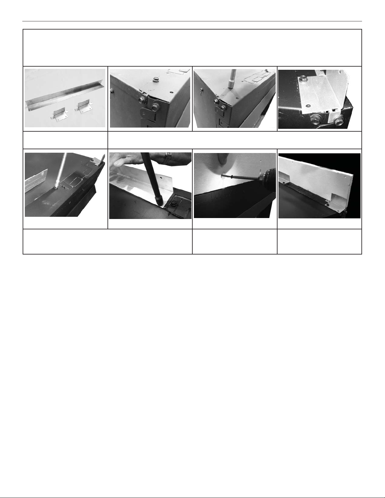
5. Installing Non-Combustible Fireboard Standoff - All Models
A non-combustible standoff board is provided for all model fi replaces to prevent overlap of drywall or other material of portions of the
fi replace that may be prone to the buildup of heat. It is supported by a middle bracket and two side brackets.
Separate and note metal side
(2) and center (1) brackets.
Step 2: Remove the three screws that align with the clearance
screw holes from the top of the unit. Secure the center bracket to
the top center of the fi replace.
Step 1: Remove two screws from the top and side of the unit. Bend the side bracket securing tab
over the edge of the unit and secure. Secure bracket to the top through the clearance screw hole.
Step 3: Top of front fi reboard
standoff should be fl ush with
top standoffs (not shown).
5. Rough in the Electrical Supply, if Needed
As necessary, rough in the fi replace electrical supply per NEC and local codes.
6. Install the [Optional] Blower Kit before Installation in the Framing
1. Remove the left side blower cover panel screw, and blower cover panel (see Table 12, Page 17). Retain the
panel and screw for later reinstallation.
Step 4: Fireboard standoff can
be secured to the capture screw
holes.
20
2. Slide the blower through the opening and position it with the bracket oriented to the front of the fi rebox and the
blower discharge to the rear of the fi rebox. Bend the two tabs in the fi rebox fl oor to secure the blower to the
fl oor.
3. Reinstall the blower cover panel and secure with the removed screw.
4. Access the blower supply wiring through the front of the fi replace and plug it into the junction box in the right,
rear of the fi replace (Figure 32).
5. Install the blower control switch according to its included instructions.
Innovative Hearth Products
Gemini™ and GeminiCD Series Direct-Vent Gas Fireplaces
Place the Fireplace in the Framing and Secure
7.
NOTE: Nailing fl anges, combustible members, and screw heads in areas directly adjacent to the nailing fl anges are
EXEMPT from the 1/2” clearance to combustible requirements for the fi rebox outer wrapper.
NOTE: Combustible framing may be in direct contact with the nailing fl anges and may be located within 1/2” of screw
heads and the fi rebox wrapper in areas adjacent to the nailing fl anges.
Frame the opening to the exact dimensions specifi ed in the framing details in this manual.
1. Bend out the appropriate nailing fl anges for the drywall / fi nish material to be used (Figure 11). Nailing fl anges
are provided for:
• fl ush framing,
• 1/2”, and
• 5/8” framing depths.
2. Secure the fi replace to the side framing members using the unit’s nailing fl anges—one top and bottom on each
side of the fi replace front (Figure 11). Use 8d nails or the equivalent.
Figure 11 - Nailing Flanges
Installation
900285-01 08/2016
Side
framing
Unit nailing fl ange
(no clearance to combustible
framing is required)
VENT SYSTEM PREPARATION
8. Select a Horizontal or Vertical Vent System
1. With the fi replace secured in the framing, determine the vent route and identify the exterior termination location.
The following sections describe vertical (roof) and horizontal (exterior wall) vent applications. Use only approved
vent components (Page 8 and Pages 48-49).
NOTE: This fi replace must be vented directly to the outside.
The vent system may not service multiple appliances, and must never be connected to a
fl ue serving a separate solid fuel burning appliance.
NOTE: The vent pipe is tested to be run inside an enclosed wall (such as a chase). There is no requirement for
inspection openings in the enclosing wall at any of the joints in the vent pipe.
WARNING
21
Innovative Hearth Products
Gemini™ and GeminiCD Series Direct-Vent Gas Fireplaces
9. Install the Vent Restrictor (if necessary)
1. Use the vent run descriptions in Figure 12 to determine if a vent restrictor is necessary.
2. If necessary, assemble the vent restrictor and wing as detailed in Figures 12 and 15.
3. If necessary, install the appropriate vent restrictor (Figures 13 and 14).
NOTE: If installing the vent restrictor in a rear vent application, ensure the factory-installed intake air baffl e is in place (Figure 14).
NOTE: The vent restrictor is shipped in the fi rebox.
Installation
900285-01 08/2016
Figure 12 - When to use a vent restrictor
2 1/2”
None
40
20
5
3
2
Break-Away
horizontal run (flat to near level)
Vertical Height (ft)
25 ft Maximum
3” Base + wing3” Base
60 ft Maximum vertical run
Vertical Height (ft) from top of unit
6 ft Minimum vertical run
*
60
40
10
6
***
6 ft Minimum
vertical run
*
Figure 13 - Vent restrictor installation, Top vent
U-Shaped Vent
Restrictor
Inner
Fireplace
Collar
Appliance Top Vent Outlet
Figure 14 - Vent restrictor installation, Rear vent
Inner Fireplace Collar
Intake Air Baffl e
Appliance Rear
Vent Outlet
U-Shaped Vent
Restrictor
22
1
Elbow**
Horizontal Distance (ft)
15
5 10
1.9
* For straight runs or runs with elbows as illustrated in Vertical Vent Figures/Tables
starting on Page 28
** No rise required.
*** On 33” Models, use the 3” base restrictor. Do not raise the break-away tab.
NOTE: When venting Rear Horizontal with slip collar and termination only, install base
vent restrictor with the breakaway portion raised.
25
Figure 15 - Vent restrictor assembly
With
break-away
raised***
Base Vent Restrictor
Base Vent Restrictor + Wing
Innovative Hearth Products
Gemini™ and GeminiCD Series Direct-Vent Gas Fireplaces
Vent Restrictor with Horizontal Terminations
When horizontally terminating a vent system with a vertical vent run up to 4 ft through an exterior wall, no vent
restrictor is required.
If installing more than 4 ft of vertical venting, install the restrictor (Figure 14), from inside or outside the unit, in the
inner fi replace collar. The vent restrictor is held in place by friction.
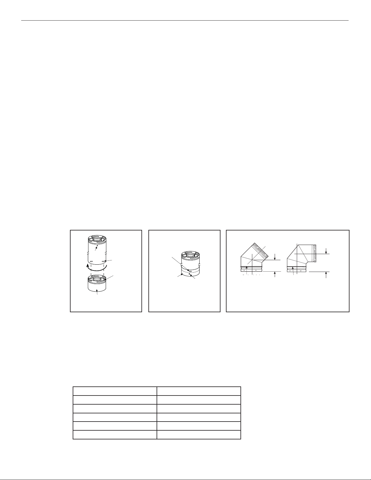
Connecting the vent pipe
Secure Vent® SV4.5 direct-vent system components are unitized concentric pipe components featuring positive twist
lock connections (Figures 16-17). All of the fi replaces covered in this document are fi tted with collars having locking
inclined channels. The dimpled end of the vent components fi t over the fi replace/vent collar to create the positive
twist lock connection.
1. Align the dimpled end over the collar, adjusting the radial alignment until the four (4) locking dimples are aligned
with the inlet of the four (4) inclined channels on the collar (Figure 16).
2. Push the vent component against the collar until it fully engages, then twist the component clockwise, running
the dimples down and along the incline channels until they seat at the end of the channels.
NOTE: The unitized design of the Secure Vent® components will engage and seal both the inner and outer vent pipe.
3. If desired, a #6 x 1/2” screw can be used at the joint, but is not required as the pipe will securely lock when
twisted (Figure 17).
Where required, a telescopic vent section (SV4.5LA) may be used to provide the installer with an option to install
in tight and confi ned spaces, or where the vent run made up of fi xed length pieces develops a joint in a undesirable
location, or will not build up to the required length. The SV4.5LA Telescopic Vent Section has an effective length of
from 1-1/2 to 7” (38 to 191 mm). The SV4.5LA is fi tted with a locking inclined channel end (identical to a normal
vent section component) and a plain end with three (3) pilot holes. Slip the plain end over the locking channel end of
a standard SV4.5 vent component the required distance and secure with three (3) screws.
Installation
900285-01 08/2016
Vent elbows
Figure 16 - Connecting vent
components
Arrow
Dimple
Locking
Incline
Channel
Appliance Collar or
Vent Section
Figure 17 - Connected vent
components
Dimple
Locking
Incline
Channel
Arrow
Figure 18 - Elbow Dimensions
4-13/16”
4 13/16 in.
(122 mm)
(122 mm)
Swivel Joint
Swivel Joint
(360°)
°
swivel)
(360
SV4.5E45
SV4.5E45
(45° elbow)
°
Elbow)
(45
Swivel Joint
Swivel Joint
(360°)
(360
SV4.5E90
(90° elbow)
°
swivel)
SV4.5E90
(90
°
Elbow)
8-1/8”
8 1/8 in.
(206 mm)
(206 mm)
Vent elbows are available in 90° and 45° confi gurations. Refer to Figure 18 for the SV4.5E45 and SV4.5E90 elbow
dimensions. The elbows feature a twist section to allow them to be routed about the center axis of their initial collar
section to align with the required direction of the next vent run element.
1. Rotate the elbow in a clockwise direction (to avoid the possibility of unlocking any of the previously connected
vent sections) for proper alignment (Figure 18). See Connecting the vent pipe for more information.
Table 13 - Effective Vent Length
Model Effective Length
SV4.5L6 4-1/2”
SV4.5L12 10-1/2”
SV4.5L24 22-1/2”
SV4.5L36 34-1/2”
SV4.5L48 46 1/2”
23
Innovative Hearth Products
Gemini™ and GeminiCD Series Direct-Vent Gas Fireplaces
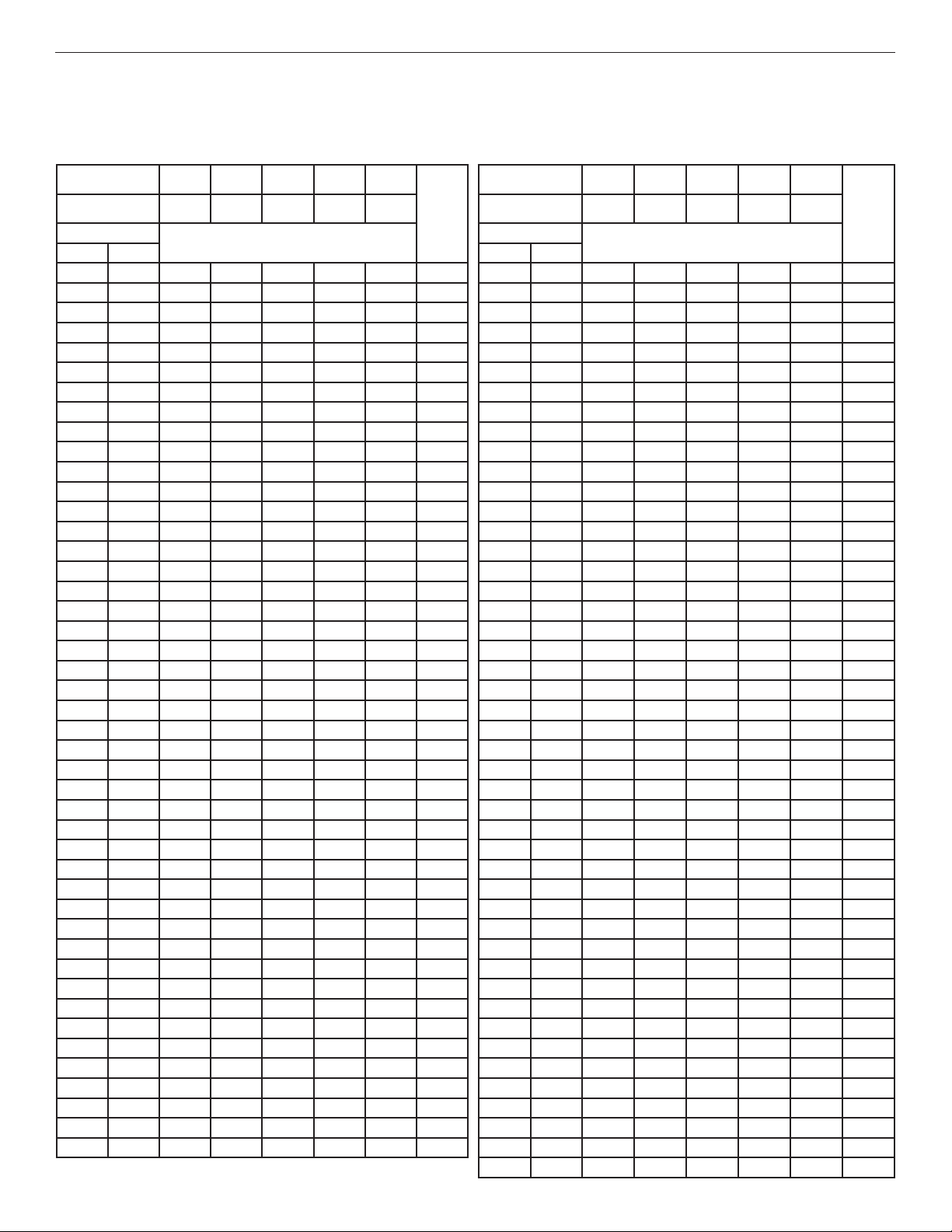
Vent section length table
Table 14 will assist calculating how many vent sections are needed for the planned vent confi guration. When a vent
section is engaged with another section, its effective length will be 1-1/2” shorter.
Table 14 - Vent Section Length
24
Nominal Section
Length (in.)
Net Section Length
(in.)
Height of Vent
in. ft in. ft
4.5 0.375 1 0 0 0 0 1 252 21 010708
9 0.75 2 0 0 0 0 2 276 23 000808
10.5 0.875 0 1 0 0 0 1 279 23.25 000066
15 1.25 1 1 0 0 0 2 280.5 23.375 100809
22.5 1.875 0 0 1 0 0 1 289.5 24.125 010067
31.5 2.625 0 3 0 0 0 3 301.5 25.125 001067
34.5 2.875 0 0 0 1 0 1 310.5 25.875 000909
37.5 3.125 1 1 1 0 0 3 325.5 27.125 0 0 0 0 7 7
43.5 3.625 0 2 1 0 0 3 330 27.5 1 0 0 0 7 8
45 3.75 0 0 2 0 0 2 345 28.75 0 0 0 10 0 10
46.5 3.875 0 0 0 0 1 1 349.5 29.125 1 0 0 10 0 11
51 4.25 1 0 0 0 1 2 372 31 0 0 0088
55.5 4.625 0 1 2 0 0 3 379.5 31.625 0 0 0 11 0 11
57 4.75 0 0 1 1 0 2 418.5 34.875 0 00099
67.5 5.625 0 0 3 0 0 3 465 38.75 0 0 0 0 10 10
69 5.75 0 0 0 2 0 2 475.5 39.625 01001011
73.5 6.125 1 0 0 2 0 3 480 40 11001012
79.5 6.625 0 1 0 2 0 3 492 41 10101012
81 6.75 0 0 0 1 1 2 499.5 41.625 00011011
91.5 7.625 0 0 2 0 1 3 504 42 10011012
93 7.75 0 0 0 0 2 2 511.5 42.625 00001111
97.5 8.125 1 0 0 0 2 3 520.5 43.375 02011114
103.5 8.625 0 0 0 3 0 3 531 44.25 02201115
108 9 1 0 0 3 0 4 538.5 44.875 10021114
117 9.75 1 0 5 0 0 6 549 45.75 10211115
118.5 9.875 1 1 0 3 0 5 558 46.5 00001212
126 10.5 0 0 1 3 0 4 562.5 46.875 10001213
130.5 10.875 1 0 1 3 0 5 568.5 47.375 01001213
135 11.25 0 0 6 0 0 6 573 47.75 11001214
139.5 11.625 0 0 0 0 3 3 580.5 48.375 0 0 1 0 12 13
142.5 11.875 1 0 0 4 0 5 589.5 49.125 0 1 2 2 10 15
144 12 1 0 0 0 3 4 595.5 49.625 1 1 1 0 12 15
154.5 12.875 1 1 0 0 3 5 604.5 50.375 0 0 0 0 13 13
160.5 13.375 0 2 0 0 3 5 615 51.25 0 1 0 0 13 14
172.5 14.375 0 0 0 5 0 5 625.5 52.125 0 2 0 0 13 15
177 14.75 1 0 0 5 0 6 631.5 52.625 1 0 1 0 13 15
186 15.5 0 0 0 0 4 4 637.5 53.125 0 1 1 0 13 15
196.5 16.375 0 1 0 0 4 5 651 54.25 00001414
207 17.25 0 0 0 6 0 6 655.5 54.625 10001415
211.5 17.625 1 0 0 6 0 7 672 56 02001416
217.5 18.125 0 1 0 6 0 7 678 56.5 10101416
229.5 19.125 0 0 1 6 0 7 688.5 57.375 11101417
232.5 19.375 0 0 0 0 5 5 697.5 58.125 00001515
241.5 20.125 0 0 0 7 0 7 702 58.5 10001516
246 20.5 1 0 0 7 0 8 712.5 59.375 11001517
6 12243648
4.5 10.5 22.5 34.5 46.5 Net Section Length (in.) 4.5 10.5 22.5 34.5 46.5
Number of Vent Sections
Nominal Section Length
Total Qty
Installation
900285-01 08/2016
(in.)
Height of Vent
7206000101516
6 12243648
Total Qty
Number of Vent Sections
 Loading...