

Astria StarLite36WS, StarLite36WH, StarLite42WS, StarLite42WH Installation And Operation Instructions Manual
P900977-00
P/N 900977-00 REV. A 06/2019
PFS
US
®
Report No. F14-168
Installation and Operation Instructions
StarLite™ Indoor and Outdoor Vent-Free Firebox
Models
StarLite36WS
StarLite36WH
StarLite42WS
StarLite42WH
Approved for use with IHP Shady Hollow and Southern Comfort log sets listed on Page 13
INSTALLER: Leave this manual with the appliance.
CONSUMER: Retain this manual for future reference.
WARNING: Carefully review the instructions supplied with the decorative type unvented room heater
for the minimum fireplace size requirement.
DO NOT INSTALL THE APPLIANCE IN THIS FIREBOX, UNLESS THIS FIREBOX MEETS THE MINIMUM
DIMENSIONS REQUIRED FOR THE INSTALLATION.
This firebox has been tested and approved under ANSI Z21.91 for use with any gas log approved to ANSI
Z21.11.2 for indoor applications and IHP MagniFlameOD log sets listed to ANSI Z21.97 for outdoor applications See Page 13.
WARNING: FOR USE ONLY WITH A LISTED, GAS-FIRED UNVENTED DECORATIVE ROOM HEATER NOT TO
EXCEED 40,000 BTU/H.
DO NOT BUILD A WOOD FIRE.
WARNING:
FIRE OR EXPLOSION HAZARD
Failure to follow safety warnings exactly could result in serious injury, death, or property damage.
- Do not store or use gasoline or other flammable vapors and liquids in the vicinity of this or any other
appliance.
- WHAT TO DO IF YOU SMELL GAS
• Do not try to light any appliance.
• Do not touch any electrical switch; do not use any phone in your building.
• Leave the building immediately.
• Immediately call your gas supplier from a neighbor’s phone. Follow the gas supplier’s instructions.
• If you cannot reach your gas supplier, call the fire department.
- Installation and service must be performed by a qualified installer, service agency or the gas supplier.
For more information, visit Astria.us.com

Thank you for your purchase. We appreciate your
business!
Please carefully read and follow all instructions in this manual. Pay
special attention to all warnings and safety information.
Following these safety, care, and operation instructions will help
ensure many years of dependable and enjoyable service from your
fireplace.
Please read and understand these instructions before installing
or operating.
SAFETY
TABLE OF CONTENTS
Safety ............................................................................................. 2
Local Codes ................................................................................... 3
Product Features ............................................................................ 3
Requirements for the Commonwealth of Massachusetts............... 3
Locating Firebox ............................................................................ 3
Product Specifications ................................................................... 4
Air for Combustion and Ventilation ................................................ 5
Installation ..................................................................................... 7
Replacement Parts ....................................................................... 12
Technical Service ......................................................................... 12
Accessories .................................................................................. 13
Parts ............................................................................................ 14
Warranty ...................................................................................... 17
Installation and repair should be done by a qualified
service person. The appliance should be inspected
before use and at least annually by a professional
service person. More frequent cleaning may be required due to excessive lint from carpeting, bedding
material, etc. It is imperative that control compartments, burners, and circulating air passageways of
the appliance be kept clean.
WARNING: Improper installation, adjustment,
alteration, service or maintenance can cause injury
or property damage. Refer to this manual for correct
installation and operational procedures. For assistance or additional information consult a qualified
installer, service agency or the gas supplier.
This appliance may be installed in an aftermarket,*
permanently located, manufactured (mobile) home,
where not prohibited by local codes.
* Aftermarket: Completion of sale, not for purpose of resale,
from the manufacturer
WARNING: This product can expose you to chemicals including Carbon Black, which is known to the State
of California to cause cancer, and Carbon Monoxide,
which is known to the State of California to cause
birth defects or other reproductive harm. For more
information go to www.P65Warnings.ca.gov
IMPORTANT: Read this owner’s manual carefully and
completely before trying to assemble, operate or
service this heater. Improper use of this fireplace can
cause serious injury or death from burns, fire, explosion, electrical shock and carbon monoxide poisoning.
WARNING: Any change to this firebox or its controls
can be dangerous.
WARNING: Do not allow fans to blow directly into
the firebox. Avoid any drafts that alter burner flame
patterns. Ceiling fans can create drafts that alter
burner flame patterns. Altered burner patterns can
cause sooting.
WARNING: Do not use a blower insert, heat exchanger insert or other accessory not approved for
use with this firebox.
Firebox front and screen become very hot when running
heater. Children and adults should be alerted to the
hazard of high surface temperature and should stay
away to avoid burns or clothing ignition. Firebox will
remain hot for a time after shutdown. Allow surface
to cool before touching.
Do not place clothing or other flammable material on
or near the appliance. Never place any objects in the
firebox or on logs.
Young children should be carefully supervised when
they are in the same room with firebox.
You must operate this fireplace with the provided
fireplace screen, hood if provided, in place. Make
sure these parts are in place and screens are closed
before running firebox. The supplied hood may not
be replaced with a hood which may be provided with
a log heater.
Astria.us.com 900977-00A2

SAFETY Continued
Keep the fireplace area clear and free from combustible materials, gasoline and other flammable vapors
and liquids.
WARNING: Vent-free products are prohibited for
bedroom and bathroom installation in the Commonwealth of Massachusetts.
Solid-fuels shall not be burned in a fireplace in which
an unvented room heater is installed.
Young children should be carefully supervised when they
are in the same room as the appliance. Toddlers, young
children and others may be susceptible to accidental
burns. A physical barrier is recommended if there are
at-risk individuals in the house. To restrict access to a
fireplace or stove, install an adjustable safety gate to keep
toddlers, young children and other at-risk individuals
out of the room and away from hot surfaces.
1. Do not use this firebox as a wood-burning fireplace. Use only
decorative unvented room heaters (log sets).
2. Do not add extra logs or ornaments such as pine cones, vermiculite
or rock wool. Using these added items can cause sooting.
3. Use only provided hood or appropriate hood accessory. See Accessories on Page 13.
4. Vent-free gas log heaters installed in these fireboxes require
fresh air ventilation to run properly. See Air for Combustion and
Ventilation, Page 5.
5. Do not run heater in firebox
• where flammable liquids or vapors are used or stored
• under dusty conditions
6. Do not use heater in this firebox to cook food or burn paper or
other objects.
7. Turn installed heater off and let cool before servicing firebox. Only
a qualified service person should service and repair firebox.
8. Do not use the firebox if it has been under water due to the shock
hazard that could result with the blower accessary (if installed) in
place.
LOCAL CODES
Install and use firebox with care. Follow all local codes. In the absence
of local codes, use the latest edition of The National Fuel Gas Code
ANSI Z223.1/NFPA 54*. Firebox must be electrically grounded in
accordance with the National Electrical Code, ANSI/NFPA70 (latest
edition).
*Available from:
American National Standards Institute, Inc.
25 West 43rd Street, 4th floor
New York, NY 10036
National Fire Protection Association, Inc.
1 Batterymarch Park
Quincy, MA 02169-7471
PRODUCT FEATURES
OPERATION
This firebox has been tested and approved under ANSI Z21.91 for use
with any gas log approved to ANSI Z21.11.2 for indoor applications
and IHP MagniFlameOD log sets listed to ANSI Z21.97 for outdoor
applications See Page 13 . It requires no outside venting or chimney
making installation easy and inexpensive.
REFRACTORY BRICK LINER
Your firebox may feature a concrete refractory brick liner. As with all
concrete liners, this liner may develop slight cracks when exposed
to heat. These cracks will not affect performance of fireplace or
vent-free gas logs.
OUTSIDE AIR KIT ACCESSORY
An optional AK4 air kit provides additional outdoor air to improve burner
efficiency and reduce build-up of condensation in the living space. Follow
instructions included with air kit.
COMMONWEALTH OF MASSACHUSETTS REQUIREMENTS
These appliances are approved for installation in the US state of
Massachusetts if the following additional requirements are met:
• Un-vented Room Heaters shall be installed in accordance with
527 CMR 30.
• Installation and repair must be done by a plumber or gas fitter
licensed in the Commonwealth of Massachusetts.
• The flexible gas line connector used shall not exceed 36 inches
(92 centimeters) in length.
• The individual manual shut-off must be a T-handle type valve.
• Unvented appliances may NOT be installed in bedrooms or
bathrooms.
• A working smoke detector must be installed in the area where
vent-free appliances are installed.
Seller of unvented propane or natural gas-fired supplemental room
heaters shall provide to each purchaser a copy of 527 CMR 30 upon
sale of the unit.
LOCATING FIREBOX
PLANNING
Plan where you will install the firebox. This will save time and money
later when you install the firebox. Before installation, consider the
following:
1. Where firebox will be located: Allow for wall and ceiling clearances
(see Installation Clearances, Page 7).
2. Everything needed to complete fireplace installation.
3. These models CANNOT be installed in a bedroom unless maximum
Btu rating of installed vent-free log set is less than 10,000 Btu/hr.
4. Proper air for combustion and ventilation (Page 5).
Astria.us.com900977-00A 3
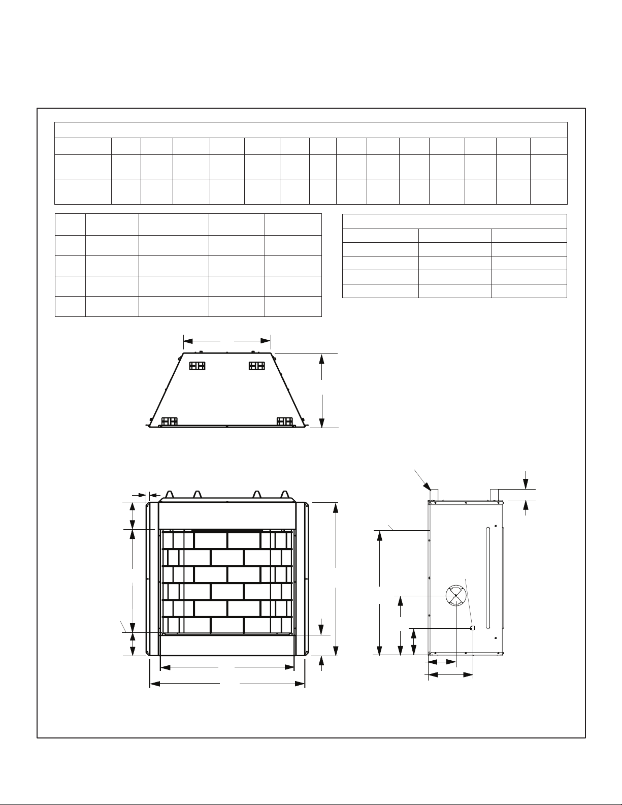
PRODUCT SPECIFICATIONS
E
Top of Bottom
Refractory
36" AND 42" MODELS
NOTE: If only one dimension is shown, dimension is the same for both 36" and 42" models.
Dimensions - Inches (millimeters)
Model No. A B C D E F G H J K L M N P
StarLite36
Series
StarLite42
Series
36
(914)28(711)
42
(1067)28(711)
41-3/4
(1061)
47-3/4
(1213)
41-1/4
(1048)
41-1/4
(1048)
23-1/2
(597)20(508)3(76)
29-1/2
(749)20(508)3(76)
8-3/8
(213)
8-3/8
(213)
15-7/8
(403)
15-7/8
(403)
7-1/2
(190)12(305)
7-1/2
(190)12(305)
1-3/8
(35)
1-3/8
(35)
5-1/2
(140)
5-1/2
(140)
34-3/8
(873)
34-3/8
(873)
Cat.
No.
F4102 StarLite36WS
F4103 StarLite36WH
F4104 StarLite42WS
F4105 StarLite42WH
Model Description Ship. Weight
1 (26)
7-1/16
(179)
OD VF Firebox, 36",
White Stacked
OD VF Firebox, 36",
White Herringbone
OD VF Firebox, 42",
White Stacked
OD VF Firebox, 42",
White Herringbone
Shipping
Volume
215 lbs 28.424 Cu. Ft.
215 lbs 28.424 Cu. Ft.
245 lbs 32.184 Cu. Ft.
245 lbs 32.184 Cu. Ft.
Top View
Interior Firebox Dimensions**
Firebox Model 36” 42”
Front Width 35 (889) 41 (1042)
Rear Width 23-1/4 (591) 29-1/4 (743)
Depth 17-3/8 (441) 17-3/8 (441)
Height 28 (711) 28 (711)
* * Dimensions are to assist you in selecting a log set that is a compatible size.
F
Inches (millimeters)
Top Stand-Off
Spacers (4
places)
Top of Firebox
Opening
G
B
6-3/16
(157)
A
C
Front View
Figure 1 - Firebox Dimensions (36" and 42" Models)
Gas Line
Bottom of
Firebox
Opening
Access -
D
Both Sides
P
J
5-3/4
(146)
H
K
L
Right Side View
Astria.us.com 900977-00A4

AIR FOR COMBUSTION AND VENTILATION
WARNING: This heater shall not be installed in a
room or space unless the required volume of indoor
combustion air is provided by the method described
in the National Fuel Gas Code, ANSI Z223.1/NFPA 54,
the International Fuel Gas Code, or applicable local
codes. Read the following instructions to insure proper
fresh air for this and other fuel-burning appliances in
your home.
Today’s homes are built more energy efficient than ever. New materials, increased insulation and new construction methods help reduce
heat loss in homes. Homeowners apply weather strip and caulk
around windows and doors to keep cold air out and warm air in.
During heating months, homeowners want their homes as airtight
as possible.
While it is good to make your home energy efficient, your home needs
to breathe. Fresh air must enter your home. All fuel-burning appliances
need fresh air for proper combustion and ventilation.
Exhaust fans, some fireboxes, clothes dryers and some fuel burning
appliances draw air from the house to operate. You must provide
adequate fresh air for these appliances. This will ensure proper venting of vented fuel-burning appliances.
PROVIDING ADEQUATE VENTILATION
The following are excerpts from National Fuel Gas Code, ANSI Z223.1/
NFPA 54, Air for Combustion and Ventilation.
All spaces in homes fall into one of the three following ventilation
classifications:
1. Unusually Tight Construction
2. Unconfined Space
3. Confined Space
Information on Pages 5 through 7 will help you classify your space
and provide adequate ventilation.
Unusually Tight Construction
Air that leaks around doors and windows may provide enough fresh
air for combustion and ventilation. However, in buildings of unusually
tight construction, you must provide additional fresh air.
Unusually tight construction is defined as construction where:
a. walls and ceilings exposed to outside atmosphere have a con-
tinuous water vapor retarder with a rating of one perm (6 x 10
kg per pa-sec-m2) or less with openings gasketed or sealed and
b. weather stripping has been added on openable windows and
doors and
c. caulking or sealants are applied to areas such as joints around
window and door frames, between sole plates and floors, between wall-ceiling joints, between wall panels, at penetrations
for plumbing, electrical and gas lines and at other openings.
If your home meets all three criteria above, you must provide
additional fresh air. See Ventilation Air From Outdoors, Page 6.
If your home does not meet all
Determining Fresh-Air Flow for Firebox Location.
three criteria above, proceed to
-11
Confined and Unconfined Space
The National Fuel Gas Code, ANSI Z223.1/NFPA 54 defines a confined
space as a space whose volume is less than 50 cubic feet per 1,000
Btu per hour (4.8 m3 per kw) of the aggregate input rating of all appliances installed in that space and an unconfined space as a space
whose volume is not less than 50 cubic feet per 1,000 Btu per hour
(4.8 m3 per kw) of the aggregate input rating of all appliances installed
in that space. Rooms communicating directly with the space in which
the appliances are installed*, through openings not furnished with
doors, are considered a part of the unconfined space.
* Adjoining rooms are communicating only if there are doorless
passageways or ventilation grills between them.
DETERMINING FRESH-AIR FLOW FOR HEATER LOCATION
Determining if You Have a Confined or Unconfined Space Using
the Standard Method
Use this work sheet to determine if you have a confined or unconfined
space.
Space: Includes the room in which you will install heater plus any
adjoining rooms with doorless passageways or ventilation grills
between the rooms.
1. Determine the volume of the space (length x width x height).
Length x Width x Height = __ cu. ft. (volume of space)
Example: Space size 22 ft. (length) x 18 ft. (width) x 8 ft. (ceiling
height) = 3168 cu. ft. (volume of space)
If additional ventilation to adjoining room is supplied with grills or
openings, add the volume of these rooms to the total volume of the
space.
2. Multiply the space volume by 20 to determine the maximum Btu/
Hr the space can support.
_____ (volume of space) x 20 = (Maximum Btu/Hr the space can
support)
Example: 3168 cu. ft. (volume of space) x 20 = 63,360 (maximum
Btu/Hr the space can support)
3. Add the Btu/Hr of all fuel burning appliances in the space.
Vent-free heater _____ Btu/Hr
Gas water heater* _____ Btu/Hr
Gas furnace _____ Btu/Hr
Vented gas heater _____ Btu/Hr
Gas fireplace logs _____ Btu/Hr
Other gas appliances*
TotaL = _____ Btu/Hr
* Do not include direct-vent gas appliances. Direct-vent draws
combustion air from the outdoors and vents to the outdoors.
Example:
Gas water heater 40,000 Btu/Hr
Vent-free heater + 39,000 Btu/Hr
Total = 79,000 Btu/Hr
+ _____ Btu/Hr
Astria.us.com900977-00A 5
AIR FOR COMBUSTION AND VENTILATION Continued
Into
Outlet
A
Crawl Space
4. Compare the maximum Btu/Hr the space can support with the
actual amount of Btu/Hr used.
________ Btu/Hr (maximum the space can support)
________ Btu/Hr (actual amount of Btu/Hr used)
Example: 63,360 Btu/Hr (maximum the space can support)
79,000 Btu/Hr (actual amount of Btu/Hr used)
The space in the above example is a confined space because the actual
Btu/Hr used is more than the maximum Btu/Hr the space can support.
You must provide additional fresh air. Your options are as follows:
A. Rework worksheet, adding the space of an adjoining room. If the
extra space provides an unconfined space, remove door to adjoining room or add ventilation grills between rooms. See Ventilation
Air From Inside Building, Page 6.
B. Vent room directly to the outdoors. See Ventilation Air From
Outdoors.
C. Install a lower Btu/Hr heater, if lower Btu/Hr size makes room
unconfined.
If the actual Btu/Hr used is less than the maximum Btu/Hr the space
can support, the space is an unconfined space. You will need no additional fresh air ventilation.
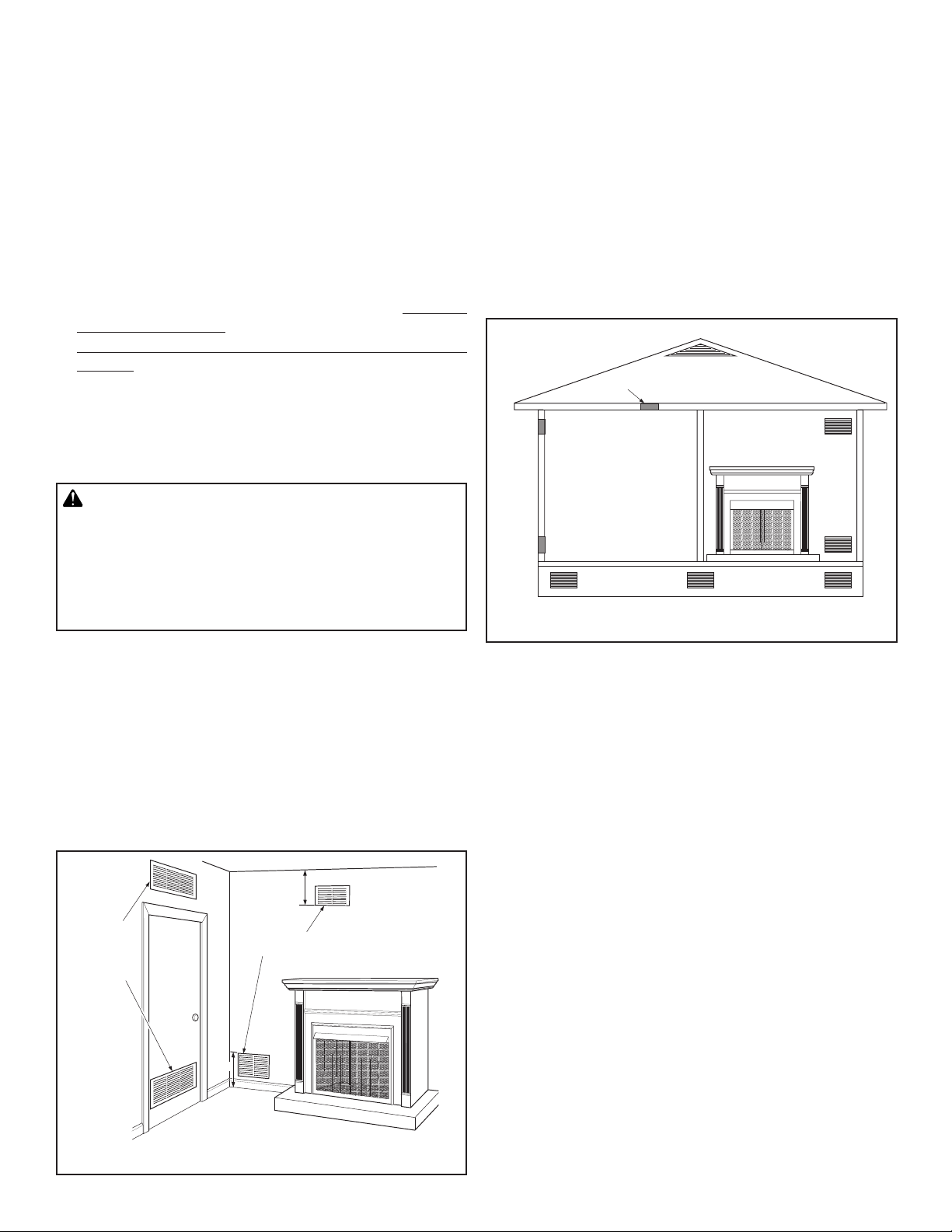
Ventilation Air From Outdoors
Provide extra fresh air by using ventilation grills or ducts. You must
provide two permanent openings: one within 12" of the ceiling and
one within 12" of the floor. Connect these items directly to the outdoors or spaces open to the outdoors. These spaces include attics
and crawl spaces. Follow the National Fuel Gas Code, ANSI Z223.1/
NFPA 54, Air for Combustion and Ventilation for required size of
ventilation grills or ducts.
IMPORTANT: Do not provide openings for inlet or outlet air into attic
if attic has a thermostat-controlled power vent. Heated air entering
the attic will activate the power vent.
Outlet
Air
ir
Ventilated
Attic
To Attic
WARNING: If the area in which the heater may be
operated does not meet the required volume for indoor
combustion air, combustion and ventilation air shall
be provided by one of the methods described in the
National Fuel Gas Code, ANSI Z223.1/NFPA 54, the International Fuel Gas Code, or applicable local codes.
VENTILATION AIR
Ventilation Air From Inside Building
This fresh air would come from an adjoining unconfined space. When
ventilating to an adjoining unconfined space, you must provide two
permanent openings: one within 12" of the ceiling and one within 12"
of the floor on the wall connecting the two spaces (see options 1 and
2, Figure 2). You can also remove door into adjoining room (see option
3, Figure 2). Follow the National Fuel Gas Code, ANSI Z223.1/NFPA
54, Air for Combustion and Ventilation for required size of ventilation
grills or ducts.
12"
Ventilation
Grills
Adjoining
Room,
Option 1
Or
Remove
Door into
Adjoining
Room,
Option
3
Ventilation Grills
Into Adjoining Room,
Option 2
12"
Inlet
Air
Inlet Air
Figure 3 - Ventilation Air from Outdoors
To
Crawl
Space
Ventilated
Figure 2 - Ventilation Air from Inside Building
Astria.us.com 900977-00A6
INSTALLATION
WARNING: A qualified service person must install
firebox. Follow all local codes.
WARNING: Never install the firebox
• in a bedroom or bathroom*
• in a recreational vehicle
• where curtains, furniture, clothing or other flammable
objects are less than 36" from front or 42" from top
of firebox. For side clearances see Figure 4
• in high traffic areas
• in windy or drafty areas
* Unless the installed log set is rated at 10,000 Btu/
Hr or less.
B. Clearances from top of firebox opening to ceiling should not be
less than 42".
C. When firebox is installed on carpeting or other combustible material,
other than wood flooring, firebox should be installed on a metal or
wood panel extending full width and depth of enclosure.
D. Clearances from bottom of firebox to floor is 0".
These fireboxes can be installed as freestanding units against a wall
with approved, optional cabinet mantels (see Accessories, Page 13)
or as a built-in unit. Clearances are the same for either installation
method.
CAUTION: Do not install firebox directly on carpet
or vinyl.
CAUTION: Log heaters installed in this firebox
create warm air currents. These currents move heat
to wall surfaces next to firebox. Installing firebox next
to vinyl or cloth wall coverings or operating firebox
where impurities (such as, but not limited to, tobacco
smoke, aromatic candles, cleaning fluids, oil or kerosene lamps, etc.) in the air exist, may discolor walls
or cause odors.
IMPORTANT: Vent-free gas log heaters add moisture to the air. Although this is beneficial, installing firebox in rooms without enough
ventilation air may cause mildew to form from too much moisture.
See Air for Combustion and Ventilation, Page 5.
IMPORTANT: Make sure firebox is level. If firebox is not level, log set
will not work properly.
NOTE: Your firebox is designed to be used in zero clearance installations. Wall or framing material can be placed against any exterior
surface on rear, sides, top or bottom of firebox, except where standoff
spacers are integrally attached. If standoff spacers are attached to
firebox, these spacers can be placed directly against wall or framing
materials.
Use dimensions shown for rough openings to create the easiest
installation (see Built-In Firebox Installation, Page 8).
INSTALLATION CLEARANCES
Example
*
*Minimum 16" from Side Wall
Figure 4 - Minimum Clearance for Combustible to Wall
Mantel Clearances for Built-In Installation (see Figure A, Page 9)
If placing custom mantel above built-in firebox, you must meet minimum allowable clearance between mantel shelf and top of firebox
opening shown in Figure 4. These are minimum allowable mantel
clearances for a safe installation. Use larger clearances wherever possible to minimize heating of objects and materials placed on mantel.
CAUTION: Do not allow vent-free gas log heater
to touch or extend beyond fireplace screen.
WARNING: Maintain the minimum clearances. If you
can, provide greater clearances from floor, ceiling and
adjoining wall.
Carefully follow these instructions. This will ensure safe installation.
Minimum Wall and Ceiling Clearances (see Figure 4)
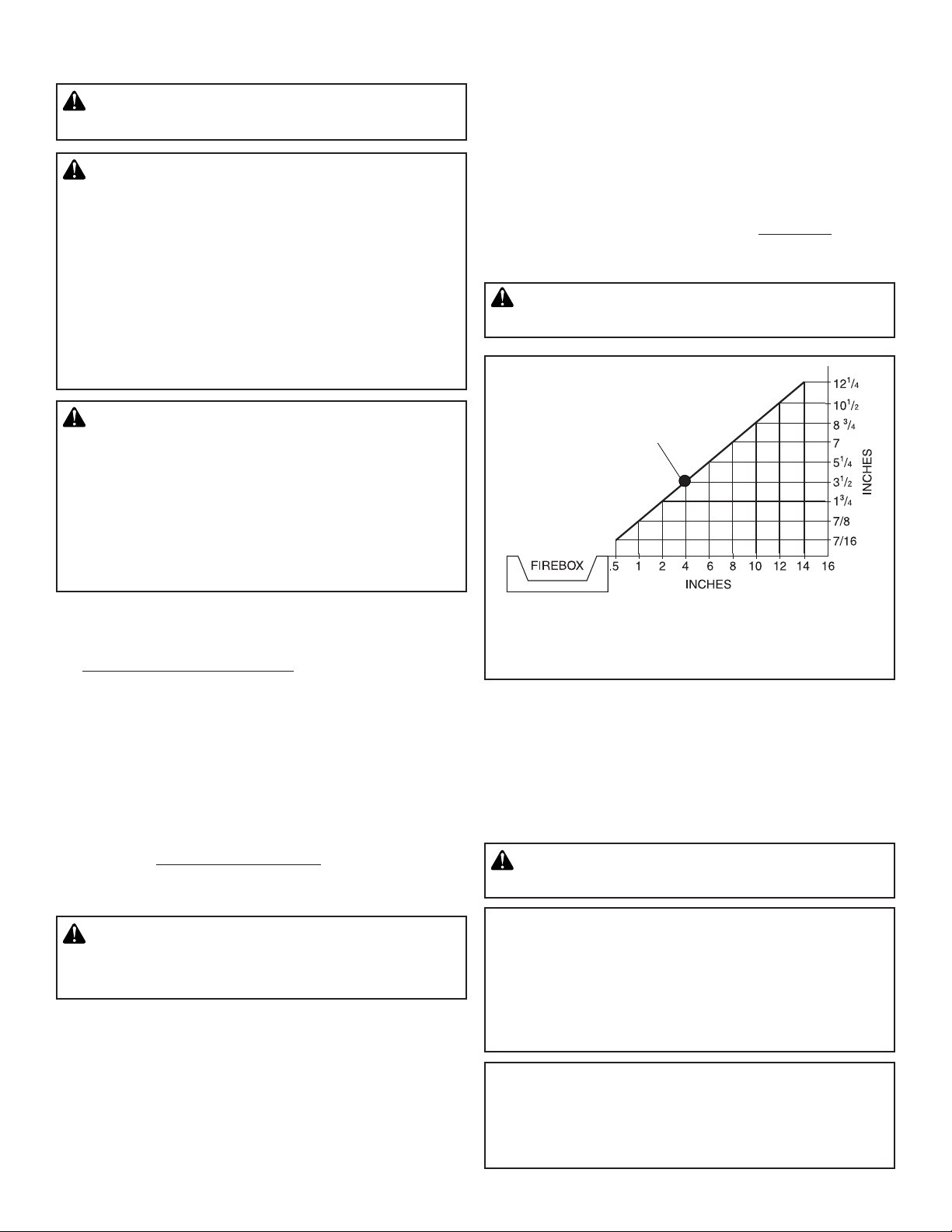
A. Clearances from side of fireplace cabinet to any combustible
material and wall should follow diagram in Figure 4.
Example: The face of a mantel, bookshelf, etc. is made of com-
bustible material and protrudes 3-1/2" from wall. This combustible
material must be 4" from side of fireplace cabinet (see Figure 4).
Astria.us.com900977-00A 7
NOTICE: Surface temperatures of adjacent walls and
mantels become hot during operation. Walls and
mantels above firebox may become hot to the touch.
If installed properly, these temperatures meet the
requirement of the national product standard. Follow
all minimum clearances shown in this manual.
NOTICE: If your installation does not meet the minimum
clearances shown, you must do one of the following:
• raise the mantel to an acceptable height
• remove the mantel

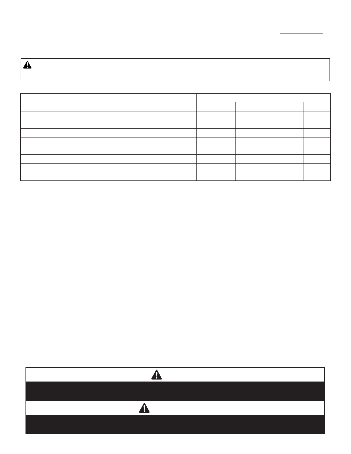
BUILT-IN FIREBOX INSTALLATION
1/2” Airspace Clearance
To Sides And Back
No Material Within
The Face Opening
Combustible Materials
Allowed Flush With
The Face Front
No Combustibles
Below The Top Spacers
Non-combustible Material
Only (field provided)
Do NOT Overlap
Material Within
The Face Opening
1/2”
Airspace
Clearance
To Back
TOP VIEW
SIDE VIEW
5”
Combustible Material
May Overlap The
Face Bottom Up To 2”
Below The Face Opening
No Material
Allowed in
This Area
1/2” Clearance
1/2” Airspace Clearance
To Sides And Back
Nailing Flange May
Make Direct Contact
With Combustible
Framing
Non-combustible Material
Only (field provided) May
Overlap the Top Face
Non-combustible Material
Only (field provided) May
Overlap the Face
Extension
Built-in installation of this firebox involves
installing firebox into a framed-in enclosure.
This makes the front of firebox flush with
wall. If installing a mantel above firebox, you
must follow clearances shown in Figure 4.
Follow these instructions to install firebox
in this manner.
1. Frame in rough opening. Firebox framing
should be constructed of 2 x 4 lumber
or heavier. Use dimensions in table and
rough opening layout in Figure 6a.
Adjust framing so that firebox is flush
with finished wall surface. If installing
in a corner, use dimensions in Figures
6b, 6c and 6d for rough opening.
2. Install gas piping to firebox location. See
Installing Gas Line, Page 10 and Connecting to Gas Supply in log set owner’s
manual.
3. Carefully set firebox in front of rough
opening with back of firebox inside wall
opening.
4. Carefully insert firebox into rough opening.
5. Attach firebox to wall studs using nails
or wood screws through holes in nailing
flange (see Figure 5).
6. Install and properly test gas log heater.
Follow installation instructions included
with vent-free gas log heater that is being
installed.
INSTALLATION Continued
Figure 5 - Minimum Mantel Clearances for Built-In Installation
Figure B
Astria.us.com 900977-00A8
Optional
Hearth
16" (407mm)
Optional
Hearth
Extension
16"
40"
40"
(1016mm)

INSTALLATION Continued
Corner
Installation
A
C
D
H
F
G
E
Back Wall Of
Chase/Enclosure
Including Finishing
Materials If Any
Rough Framing Face
(Unfinished Shown)
C
G
A
Parallel Installation
Rough Framing Face
(Unfinished Shown)
Back Wall Of
Chase/Enclosure
Including Finished
Materials - If Any
FRAMING SPECIFICATIONS
Opening StarLite36 StarLite42
A
B
C
D
E
F
G
H
Table 1 - This Table Corresponds To Figure 6a, 6b and 6c
42-3/4" (1086) 48-3/4" (1238)
46-1/2" (1181) 46-1/2" (1181)
23-5/8" (600) 29-5/8" (753)
11-1/4" (286) 14-1/4" (362)
63-1/2" (1613) 69-1/2" (1765)
31-3/4" (807) 34-3/4" (883)
20-1/2"( 521) 20-1/2"( 521)
44-1/4" (1124) 49-1/8" (1248)
Figure 6b
*Increase Framing Height by 34" when using an Optional Drain Pan
Figure 6a
Figure A
19 (483)
17 (432)
15 (381)
13 (330)
11 (280)
9 (229)
B*
12
(305)
10
(254)
A
Mantel depth
WITH
HOOD
INSTALLED
8
(203)
6
(152)
4
(102)
(51)
Header
2
Fireplace
Hood
Figure 6c
Mantel Clearances
Mantel depth
23 (585)
8
(203)
WITHOUT
HOOD
INSTALLED
4
(102)
6
(152)
2
(51)
21 (534)
19 (483)
17 (432)
15 (381)
13 (330)
12
(305)
10
(254)
Astria.us.com900977-00A 9
inches (millimeters)
Fireplace
Top of Firebox
Opening

INSTALLATION Continued
IMPORTANT: When finishing your firebox, combustible materials
such as wall board, gypsum board, sheet rock, drywall, plywood,
etc. may be butted up next to sides and top of firebox. Combustible
materials should never overlap firebox front facing.
WARNING: Do not allow any combustible materi-
als to overlap firebox front facing.
IMPORTANT: Noncombustible materials such as brick, tile, etc. may
overlap front facing, but should never cover any necessary openings
like louvered slots.
WATERPROOFING THE FIREPLACE
Although this fireplace is designed to operate safety outdoors, rain
may enter the hearth area (along with condensation) that could cause
an undue amount of water to collect in the fireplace bottom.
To prevent water collection, the builder must provide a means
to drain water from under the fireplace by building or installing
a water collector of the builders choice, before positioning the
fireplace in its location.
Special care must be taken when the fireplace is installed against an
exterior wall. The enclosure surrounding the fireplace on the sides
and back must be treated as an exterior wall.
Innovative Hearth Products (IHP) provides an optional drain pan to
assist weatherproofing the fireplace.
H4651 DPSS36 Drain Pan for StarLite36, H4652 DPSS42 Drain Pan
forStarLite42.
WARNING: Do not allow noncombustible materials
to cover any necessary openings like louvered slots.
WARNING: Use only noncombustible mortar or
adhesives when overlapping the front facing with
noncombustible facing material.
INSTALLING FIREBOX USING OPTIONAL ACCESSORY MANTELS
WARNING: A qualified service person must install
firebox. Follow all local codes.
This firebox may be installed using a cabinet mantel accessory against
a wall in your home. Firebox and cabinet mantel can be installed directly on floor. A trim kit is included with mantel accessories. Follow
instructions with mantel for installation.
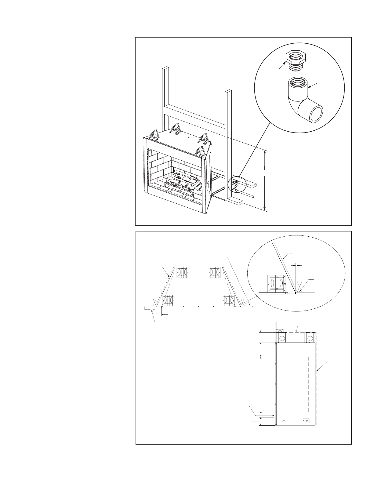
INSTALLING GAS LINE
NOTICE: A qualified service person must connect heater
to gas supply. Follow all local codes.
IMPORTANT: See Connecting to Gas Supply in your log set owner’s
manual for details on gas hookup.
You may run gas line from either side or back of firebox (see Figure
7a, Page 11). Decide which side you want to run gas line from.
NOTE: This is one option for installing shutoff valve. Check local codes
for equipment shutoff valve location requirements.
Locate recessed knockout in one firebrick liner (see Figure 1, Page
4 and Page 14). Firmly tap center of knockout with a chisel until it
is released. Carefully chisel rough edges of hole you have made to
smooth edges. This hole will line up with hole in outer casing.
CAUTION: Do not use excessive force to remove the
knockout. Too much force may damage the firebrick
concrete insert.
Astria.us.com 900977-00A10
1/2” Airspace Clearance
To Sides And Back
No Material Within
The Face Opening
Combustible Materials
Allowed Flush With
The Face Front
No Combustibles
Below The Top Spacers
Non-combustible Material
Only (field provided)
Do NOT Overlap
Material Within
The Face Opening
1/2”
Airspace
Clearance
To Back
TOP VIEW
SIDE VIEW
5”
Combustible Material
May Overlap The
Face Bottom Up To 2”
Below The Face Opening
No Material
Allowed in
This Area
1/2” Clearance
1/2” Airspace Clearance
To Sides And Back
Nailing Flange May
Make Direct Contact
With Combustible
Framing
Non-combustible Material
Only (field provided) May
Overlap the Top Face
Non-combustible Material
Only (field provided) May
Overlap the Face
When Planning for the installation of the fireplace, the framing height must be increased
from 46-1/2" to 47-1/4", when installing the drain
pan. An additional space below the fireplace will
also be required to plumb a drain line.
Step 1. Seal all joints, gaps and corners around
the bottom of the drain pan before
positioning the fireplace on its location
(Figure 7a).
Step 2. On the exposed drain hole, install a PVC
threaded coupling reducer, 3/4" x 1/2"
going from the top of the pan down
through the hole. Apply a silicone-based
sealant around the base and threads
before installation.
Step 3. Holding the reducer coupling with a
wrench, thread a 3/4", 90 degree, PVC
elbow to the reducer until it is tight to
the metal.
Step 4. Add additional piping to route the drain
to an appropriate location.
INSTALLATION Continued
Threaded
Reducer
3/4 x 1/2
(PVC)
Drain Connector Detail
47 1/4
Threaded
Elbow 3/4
@ 90
º
(PVC)
NOTE: To assure proper drainage, the fireplace
must be installed on a leveled surface.
CLEARANCES
Minimum clearance to combustibles for the
fireplace is as follows; sides and back – 1/2"
(13mm), combustible floor – 0" (0mm), adjacent
wall 6" (152mm), ceiling – 72" (1829mm). Refer
to Figure 7b on this Page and Figure 4 on Page
7 for more detail.
NOTE: Clearance behind the nailing flange for
both fireplace models is 1/2" (13mm).
NOTE: Adjacent wall considerations are for
an adjacent wall to only a single side. Walls
should not be placed at the minimum distance
on both sides of the fireplace. Allow at least 4
feet on one side of the fireplace.
Figure 7a
Figure 7b
Astria.us.com900977-00A 11

TYPICAL INSTALLATION
Weatherproof
INSTALLATION Continued
Enclosure
Fireplace
Figure 8
Face Top
Place the hood lip
up and under the
face top opening
Hood Lip
STEP 1
Optional Drain Pan
INSTALLING FIREPLACE HOOD
These brushed stainless hood trim kits (36" hood kit - Catalog no. F4128
and 42" hood kit - Catalog no. F4129) may be used with these outdoor gas
fireplaces. These kits contain one brushed stainless hood, two (2) screws
and these instructions.
Installation Instructions:
To install the hood trim kit, refer to Figure 9 and follow the steps outlined
below:
Step 1. Turn off the fireplace and allow it to cool before proceeding.
Step 2. Place the hood lip under the face top opening, as shown in Figure
9 - Step 1. Attach the hood with two (2) screws, one each side,
as shown in Figure 9 - Step 2. Completed installation is shown in
Figure 9 - Step 3.
Attaching Screw
(seen from below)
STEP 2
STEP 3
Figure 9
REPLACEMENT PARTS
NOTE: Use only original replacement parts. This will protect your
warranty coverage for parts replaced under warranty.
Normally, all parts should be ordered through your IHP distributor
or dealer. Parts will be shipped at prevailing prices at time of order.
NEVER USE SUBSTITUTE MATERIALS. USE OF NON-APPROVED
PARTS CAN RESULT IN POOR PERFORMANCE AND SAFETY HAZARDS.
TECHNICAL SERVICE
You may have further questions about installation, operation, or
troubleshooting. Please contact your IHP dealer for any questions or
concerns. When contacting your dealer please have your model and
serial numbers of your appliance ready. You can also visit our web site
at Astria.us.com
Astria.us.com 900977-00A12

ACCESSORIES
NOTICE: All accessories may not be available for all fireplace models.
Purchase these accessories from your local dealer. If they can not supply these accessories contact IHP at Astria.us.com for information. You
can also write to the address listed on the back Page of this manual
REQUIRED BURNERS (For Outdoor Use Only!)
24" Outdoor Burner Kits
Cat.# Model Description
F0558
F0560
F0557
F0559
F2081A
F2081B
F2082A
F2082B
F0087A
F0087B
F0088A
F0088B
MagniFlameOD
-24NM
MagniFlameOD
-24PM
MagniFlameOD
-24NE
MagniFlameOD
-24PE
Outdoor Log Sets, Concrete
Shady Hollow
24A
Shady Hollow
24B
Shady Hollow
30A
Shady Hollow
30B
Southern
Comfort24A
Southern
Comfort24B
Southern
Comfort30A
Southern
Comfort30B
Cat. No. Model Description
H4651 DPSS36 Drain Pan (36)
H4652 DPSS42 Drain Pan (42)
24" Magniflame Large
Outdoor Stainless
24" Magniflame Large
Outdoor Stainless
24"Magniflame Large
Outdoor Stainless
Burner. Electronic
24" Magniflame Large
Outdoor Stainless
Burner, Electronic
24", VF Logs, 1/2
24", VF Logs, 2/2
30", VF Logs, 1/2
30", VF Logs, 2/2
Drain Pan
Burner ,Millivolt
Burner, Millivolt
Ignition
Ignition
24" VF Log, 1/2
24" VF Log, 2/2
30" VF Log, 1/2
30" VF Log, 2/2
Outside Air Gate & Duct Kit
Cat. No. Model Description
H3991 OAK-UVFRC
(ref. Form #750206M)
Outside Air Gate &
Duct Kit
Outside Air Gate & Duct Kit
These kits have an air gate assembly, 4" diameter
duct and a termination hood. The air gate allows
adjustment of the amount of outside air delivered
to the fire for combustion. Only one kit, located
on the right side of the fireplace, is required.
Touch-Up Paint Kits
Repair minor scratches and discoloration of the fireplace black
P
T
A
N
I
painted surfaces with the touch-up
paint kits.
Cat. No. Model Description
F4032 ----
F1882 SCTPSAB
Black touch-up paint,
firebox interior
Black touch-up paint,
powder coat exterior
Hood Kit
This attractive brushed stainless Hood Kit is
easy to install and enhances the appearance of
the appliance.
Outdoor Hood Kit
Cat. No. Model Description
F4128 Hood36ODSL 36” Hood Kit
F4129 Hood42ODSL 42” Hood Kit
Creamer Rust Cappuccino
Refractory Stain Kits
Use the Refractory Stain Kits to give white refractory
panels a new look.
Kit includes foam roller, roller handle, paint tray, and
one can of stain. Available stain colors are Creamer
(ivory), Rust (terra cotta), and Cappuccino (rosy taupe).
Refractory Stain Kits
Cat. No. Model Description
H8176 BSK-CR Creamer
H8177 BSK-RT Rust
H8178 BSK-CP Cappuccino
Astria.us.com900977-00A 13

PARTS
13
12
17
18
3
14
11
3H
15
1
2
1H
2H
7
(RIGHT SIDE)
(RIGHT SIDE)
10
MODELS STARLITE36WS, STARLITE36WH, STARLITE42WS AND STARLITE42WH
Cat. No. Model Description
F4102 StarLite36WS
F4103 StarLite36WH
F4104 StarLite42WS
F4105 StarLite42WH
OD VF Firebox, 36",
White Stacked
OD VF Firebox, 36",
White Herringbone
OD VF Firebox, 42",
White Stacked
OD VF Firebox, 42",
White Herringbone
See Page 16
See Page 16
WARNING
Never use substitute materials. Use of non-approved parts
can result in poor performance and safety hazards.
Astria.us.com 900977-00A14
PARTS
This list contains replaceable parts used in your firebox. When ordering parts, follow the instructions listed under Replacement Parts on
Page 12 of this manual.
WARNING: Contact an IHP dealer to obtain any of these parts. Never use substitute materials not approved
by IHP. Use of non-approved parts can result in poor performance and safety hazards.
Item No. Description
10 Top Frame H4933 1 H4934 1
11 Bottom Frame H4935 1 H4936 1
12 Corner Post (LH) H4937 1 H4937 1
13 Corner Post (RH) H4938 1 H4938 1
14 Stand-Off Bracket H2716 4 H2716 4
17 Screen H4926 2 H4927 2
18 Screen Rod H4939 2 H4940 2
22 Flex Connector 93L32 2 93L32 2
StarLite 36 StarLite 42
Part No. Qty. Part No. Qty.
WARNING
Failure to position the parts in accordance with these diagrams or failure to use only parts specifically
approved with this appliance may result in property damage or personal injury.
AVERTISSEMENT
Risque de dommages ou de blessures si les pièces ne sont pas installées conformément à ces schémas
et ou si des pièces autres que celles spécifiquement approuvées avec cet appareil sont utilisées.
Astria.us.com900977-00A 15
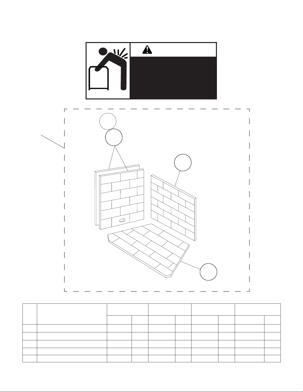
PARTS
2
1
MODELS STARLITE36WS, STARLITE36WH, STARLITE42WS AND STARLITE42WH
WARNING
LIFTING HAZARD
SINGLE -PERSON LIFT COULD
CAUSE INJURY.
USE ASSISTANCE WHEN MOVING
OR LIFTING.
3a
3
3b
3
3c
4
3d
5
No. Description
3 Refractory Panel Set, 4 pc. F3528 1 F3396 1 F3529 1 F3530 1
3a Refractory, Left (order set) --- 1 --- 1 --- 1 --- 1
3b Refractory, Right (order set) --- 1 --- 1 --- 1 --- 1
3c Refractory, Rear (order set) --- 1 --- 1 --- 1 --- 1
3d Refractory, Bottom (order set) --- 1 --- 1 --- 1 --- 1
StarLite36WS
White Stacked
Part No. Qty. Part No. Qty. Part No. Qty. Part No. Qty.
StarLite36WS
White Herringbone
StarLite42WS
White Stacked
StarLite42WH
White Herringbone
Astria.us.com 900977-00A16

Innovative Hearth Products
®
Astria
Brand Gas Fireplace
Limited Lifetime Warranty
THE WARRANTY
Innovative Hearth Products ("IHP") Limited Lifetime Warranty warrants your Astria® brand gas fireplace ("Product") to be free from defects in materials and workmanship
at the time of manufacture. The product body, firebox and barrier carry the Limited Lifetime Warranty. Ceramic glass carries the Limited Lifetime Warranty against thermal
breakage only. After installation, if covered components manufactured by IHP are found to be defective in materials or workmanship during the Limited Lifetime Warranty
period and while the Product remains at the site of the original installation, IHP will, at its option, repair or replace the covered components. If repair or replacement is not
commercially practical, IHP will, at its option, refund the purchase price or wholesale price of the IHP product, whichever is applicable. IHP will also pay IHP prevailing labor
rates, as determined in its sole discretion, incurred in repairing or replacing such components for up to five years. THERE ARE EXCLUSIONS AND LIMITATIONS to this
Limited Lifetime Warranty as described herein.
COVERAGE COMMENCEMENT DATE
Warranty coverage begins on the date of purchase. In the case of new home construction, warranty coverage begins on the date of first occupancy of the dwelling or six
months after the sale of the Product by an independent IHP dealer/distributor, whichever occurs earlier. The warranty shall commence no later than 24 months following
the date of product shipment from IHP, regardless of the installation or occupancy date.
EXCLUSIONS AND LIMITATIONS
This Limited Lifetime Warranty applies only if the Product is installed in the United States or Canada and only if operated and maintained in accordance with the printed
instructions accompanying the Product and in compliance with all applicable installation and building codes and good trade practices.
This warranty is non-transferable and extends to the original owner only. The Product must be purchased through a listed supplier of IHP and proof of purchase must be
provided. The product body, firebox and barrier carry the Limited Lifetime Warranty from the date of installation. Vent components, trim components and paint are excluded
from this Limited Lifetime Warranty. The following do not carry the Limited Lifetime Warranty but are warranted as follows:
Burner – Repair or replacement for five years from the date of installation
Gas components & electrical components – Repair or replacement for one year from the date of installation
Gaskets – Repair or replacement for one year from the date of installation
Gold & nickel plating - Replacement for two years from date of installation. Excludes tarnishing
Labor coverage – Prevailing IHP labor rates apply for the warranty period of the component
Light bulbs & batteries – Replacement for 90 days from the date of installation
Logs – Replacement for five years from the date of installation against thermal breakage only
Optional blowers & remote controls – Repair or replacement for one year from the date of installation
Optional glass doors & optional glass accessories – Repair or replacement for 90 days from the date of installation
Optional surrounds – Stone/Natural Materials: Replacement for one year against cracking or breakage due to thermal stress. Other Materials: Replacement for one
year. Excludes surface and hairline cracks and scratches or slight color changes that do not affect the operation or safety of the unit
Tempered Glass -Replacement for one year from the date of installation
Parts not otherwise listed carry a 90 day warranty from the date of installation.
Whenever practicable, IHP will provide replacement parts, if available, for a period of 10 years from the last date of manufacture of the Product.
IHP will not be responsible for: (a) damages caused by normal wear and tear, accident, riot, fire, flood or acts of God; (b) damages caused by abuse, negligence, misuse, or
unauthorized alteration or repair of the Product affecting its stability or performance (The Product must be subjected to normal use. The Product is designed to burn either
natural or propane gas only. Burning conventional fuels such as wood, coal or any other solid fuel will cause damage to the Product, will produce excessive temperatures
and could result in a fire hazard.); (c) damages caused by failing to provide proper maintenance and service in accordance with the instructions provided with the Product;
(d) damages, repairs or inefficiency resulting from faulty installation or application of the Product.
IHP is not responsible for inadequate fireplace system draft caused by air conditioning and heating systems, mechanical ventilation systems, or general construction conditions
which may generate negative pressure in the room in which the appliance is installed. Additionally IHP assumes no responsibility for drafting conditions caused by venting
configurations, adjoining trees or buildings, adverse wind conditions or unusual environmental factors and conditions that affect the operation of the unit.
This Limited Lifetime Warranty covers only parts and labor as provided herein. In no case shall IHP be responsible for materials, components or construction, which are not
manufactured or supplied by IHP or for the labor necessary to install, repair or remove such materials, components or construction. Additional utility bills incurred due to
any malfunction or defect in equipment are not covered by this warranty. All replacement or repair components will be shipped F.O.B. from the nearest stocking IHP factory.
LIMITATION ON LIABILITY
It is expressly agreed and understood that IHP’s sole obligation and the purchaser’s exclusive remedy under this warranty, under any other warranty, expressed or implied,
or in contract, tort or otherwise, shall be limited to replacement, repair, or refund, as specified herein.
In no event shall IHP be liable for any incidental or consequential damages caused by defects in the Product, whether such damage occurs or is discovered before or after
repair or replacement, and whether such damage is caused by IHP’s negligence. IHP has not made and does not make any representation or warranty of fitness for a particular
use or purpose, and there is no implied condition of fitness for a particular use or purpose.
IHP makes no expressed warranties except as stated in this Limited Lifetime Warranty. The duration of any implied warranty is limited to the duration of this expressed warranty.
No one is authorized to change this Limited Lifetime Warranty or to create for IHP any other obligation or liability in connection with the Product. Some states and provinces
do not allow the exclusion or limitation of incidental or consequential damages, so the above limitations or exclusions may not apply to you. The provisions of this Limited
Lifetime Warranty are in addition to and not a modification of or subtraction from any statutory warranties and other rights and remedies provided by law.
INVESTIGATION OF CLAIMS AGAINST WARRANTY
IHP reserves the right to investigate any and all claims against this Limited Lifetime Warranty and to decide, in its sole discretion, upon the method of settlement.
To receive the benefits and advantages described in this Limited Lifetime Warranty, the appliance must be installed and repaired by a licensed contractor approved by IHP.
Contact IHP at the address provided herein to obtain a listing of approved dealers/distributors. IHP shall in no event be responsible for any warranty work done by a
contractor that is not approved without first obtaining IHP's prior written consent.
HOW TO REGISTER A CLAIM AGAINST WARRANTY
In order for any claim under this warranty to be valid, you must contact the IHP dealer/distributor from which you purchased the product. If you cannot locate the dealer/
distributor, then you must notify IHP in writing. IHP must be notified of the claimed defect in writing within 90 days of the date of failure. Notices should be directed to the
IHP Warranty Department at 1769 East Lawrence Street; Russellville, AL 35654 or visit our website at WWW.ASTRIA.US.COM.
Printed in U.S.A. © 2013 Innovative Hearth Products
P/N 900199-00, Rev. C 02/2018
Innovative Hearth Products
1769 East Lawrence Street • Russellville, AL 35654
17
P900977-00
Astria.us.com
Record the following important information about your appliance:
Appliance model number
Appliance serial number
Date appliance was Installed
Type of gas appliance uses
Dealer name
Innovative Hearth Products (IHP) reserves the right to make changes at any
time, without notice, in design, materials, specifications, prices and also
to discontinue colors, styles and products. Consult your local distributor for
fireplace code information.
Printed in U.S.A. © 2019 Innovative Hearth Products
P/N 900977-00 Rev. A 06/2019
18
1769 East Lawrence Street • Russellville, AL 35654
 Loading...