

Astria Sentinel36TEN, Sentinel36TEP, Sentinel42TEN, Sentinel42TEP Installation And Operation Instructions Manual
Installation and Operation Instructions
PFS
AstriaTM Direct-Vent Gas Fireplace
P/N 126773-01 Rev. A 1/2014
P126733-01
INSTALLER: Leave this manual with the appliance.
CONSUMER: Retain this manual for future reference.
A barrier designed to reduce the risk of burns
from the hot viewing glass is provided with this
appliance and shall be installed.
This appliance may be installed in an aftermarket permanently located, manufactured home (USA only) or mobile
home, where not prohibited by local codes. This appliance is only for use with the type of gas indicated on the
rating plate. This appliance is not convertible for use with other gases, unless a certified kit is used.
Models
®
Sentinel36TEN Sentinel36TEP Sentinel42TEN Sentinel42TEP
USC
Installateur : Laissez cette notice avec l’appareil.
Consommateur : Conservez cette notice pour consultation ultérieure.
Une barrière conçue pour réduire le risque de brûlure
par le hublot chaude est fournie avec l’appareil et doit
être installé.
WARNING AVERTISSEMENT AVISO
HOT GLASS WILL
CAUSE BURNS.
UNE SURFACE VITRÉE CHAUDE PEUT
CAUSER DES BRÛLURES.
EL VIDRIO CALIENTE
CAUSARÁ QUEMADURAS.
DO NOT TOUCH GLASS
UNTIL COOLED.
NEVER ALLOW CHILDREN
TO TOUCH GLASS.
WARNING: If the information in these
instructions is not followed exactly, a fire or
explosion may result causing property damage,
personal injury or death.
— Do not store or use gasoline or other
flammable vapors and liquids in the vicinity
of this or any other appliance.
— WHAT TO DO IF YOU SMELL GAS:
• Do not try to light any appliance.
• Do not touch any electrical switch; do not
use any phone in your building.
• Immediately call your gas supplier from
a neighbor’s phone. Follow the gas
supplier’s instructions.
• If you cannot reach your gas supplier, call
the fire department.
— Installation and service must be performed
by a qualified installer, service agency or the
gas supplier.
LAISSER REFROIDIR LA SURFACE VITRÉE
NE PERMETTEZ JAMAIS À UN ENFANT DE
TOUCHER LA SURFACE VITRÉE.
USTED DEBE NUNCA TOCAR
AVANT D’Y TOUCHER.
AVERTISSEMENT : Assurez-vous de bien suivre les
instructions données dans cette notice pour réduire au
minimum le risque d’incindie ou d’explosion ou pour éviter
tout dommage matériel, toute blessure ou la mort.
— Ne pas entreposer ni utilizer d’essence ni d’autres
vapeurs ou liquides inflammables dans le voisinage
de cet appareil ou de tout autre appareil.
— QUE FAIRE SI VOUS SENTEZ UNE ODEUR DE GAZ :
• Ne pas tenter d’allumer d’appareil.
• Ne touchez à aucan interrupteur. Ne pas vous
servir des téléphones se trouvant dans le bâtiment
où vous trouvez.
• Appelez immédiatement votre fournisseur de
gaz depuis un voisin. Suivez les instructions du
fournisseur.
• Si vous ne pouvez rejoindre le fournisseur de gaz,
appelez le service des incindies.
— L’installation et l’entretien doivent être assurés par un
installateur ou un service d’entretien qualifié ou par le
fournisseur de gaz.
EL VIDRIO CALIENTE.
LOS NIÑOS DEBEN NUNCA
TOCAR EL VIDRIO.

TABLE OF CONTENTS
Safety .................................................................. 2
Local Codes......................................................... 5
Product Identication ........................................... 5
Product Features ................................................. 5
Pre-installation ..................................................... 6
Location of Termination Cap ................................ 8
Requirements for the Commonwealth of
Massachusetts..................................................... 9
Venting Installation ............................................ 10
Fireplace Installation.......................................... 17
Operation ........................................................... 25
SAFETY
WARNING: Improper installation, adjustment, alteration,
service or maintenance can
cause injury or property damage.
Refer to this manual for correct
installation and operational
procedures. For assistance or
additional information consult
a qualified installer, service
agency or the gas supplier.
This appliance is only for use
with the type of gas indicated on
the rating plate. This appliance
is not convertible for use with
other gases, unless a certied
kit is used.
State of Massachusetts: The
installation must be made by a
licensed plumber or gas tter
in the Commonwealth of Massachusetts.
WARNING: This product
contains and/or generates
chemicals known to the State
of California to cause cancer or
birth defects or other reproductive harm.
Inspecting Burners............................................. 26
Cleaning and Maintenance ................................ 27
Troubleshooting ................................................. 29
Parts .................................................................. 32
Specications .................................................... 38
Wiring Diagram .................................................. 38
Replacement Parts ............................................ 39
Technical Service............................................... 39
Service Hints ..................................................... 39
Acessories ......................................................... 39
Warranty ............................................................ 40
IMPORTANT: Read this owner’s
manual carefully and completely
before trying to assemble, op-
erate or service this replace.
Improper use of this replace
can cause serious injury or
death from burns, re, explosion, electrical shock and carbon
monoxide poisoning.
DANGER: Carbon monoxide
poisoning may lead to death!
This vented gas replace is a sealed combustion gas replace designed for residential
applications. This replace must be installed
with INNOVATIVE HEARTH PRODUCTS vent
pipe components and terminations.
This fireplace complies with the National
Safety Standards and is listed and tested by
PFS Corporation to ANSI Z21.50/CSA 2.22
standard as vented gas replace.
NOTICE: Decorative product not
for use as a heating appliance.
This replace must be installed by a qualied
(certied or licensed) service person. It brings
in fresh air for combustion through the outer
pipe and combustion gases are exhausted
through the inner pipe. If the glass door assembly and venting pipe are not properly
seated, connected and sealed, carbon monoxide leakage (spillage) can occur.
Carbon Monoxide Poisoning: Early signs of
carbon monoxide poisoning resemble the u,
with headaches, dizziness or nausea. If you
have these signs, the replace may not be
working properly. Get fresh air at once! Have
replace serviced. Some people are more
www.Astria.US.com
126733-01A2
SAFETY
Continued
affected by carbon monoxide than others. These include pregnant women, people with heart
or lung disease or anemia, those under the inuence of alcohol and those at high altitudes.
Natural and Propane/LP Gas: Natural and propane/LP gas are odorless. An odor-making
agent is added to the gas. The odor helps you detect a gas leak. However, the odor added to
the gas can fade. Gas may be present even though no odor exists.
Make certain you read and understand all warnings. Keep this manual for reference. It is your
guide to safe and proper operation of this replace.
WARNING: Any change to this replace or it’s controls can be
dangerous. Do not modify this replace under any circumstances.
Any parts removed for servicing must be replaced prior to operat-
ing replace.
WARNING: Do not use a blower insert, heat exchanger insert or
other accessory not approved for use with this replace.
WARNING: This appliance is only for use with the type of gas
indicated on the rating plate. This appliance is not convertible for
use with other gases unless a certied kit is used.
WARNING: Do not allow fans to blow directly into the replace.
Avoid any drafts that alter burner ame patterns.
Due to high temperatures, the appliance should be located out of
trafc and away from furniture and draperies.
Do not place clothing or other ammable material on or near the
appliance. Never place any objects on the appliance.
Do not use this replace to cook food or burn paper or other ammable material.
This replace reaches high temperatures. Keep children and adults
away from hot surface to avoid burns or clothing ignition. Fireplace
will remain hot for a time after shutdown. Allow surface to cool
before touching.
Young children should be carefully supervised when they are in the same room
as the appliance. Toddlers, young children and others may be susceptible to
accidental burns.A physical barrier is recommended if there are at-risk individuals
in the house. To restrict access to a replace or stove, install an adjustable safety
gate to keep toddlers, young children and other at-risk individuals out of the room
126733-01A 3
and away from hot surfaces.
www.Astria.US.com

SAFETY
Continued
Young children should be carefully
supervised when they are in the same
room as the appliance. Toddlers, young
children and others may be susceptible
to accidental burns.A physical barrier
is recommended if there are at-risk
individuals in the house. To restrict
access to a replace or stove, install
an adjustable safety gate to keep
toddlers, young children and other
at-risk individuals out of the room and
away from hot surfaces.
Keep the area around your
replace clear of combustible
materials, gasoline and other
ammable vapor or liquids. Do
not run replace where these
are used or stored.
1. For propane/LP replace, do not place
propane/LP supply tank(s) inside any
structure. Locate propane/LP supply
tank(s) outdoors. To prevent performance
problems, do not use propane/LP fuel tank
of less than 100 lb. capacity.
2. If you smell gas
• shut off gas supply
• do not try to light any appliance
• do not touch any electrical switch; do not
use any phone in your building
• immediately call your gas supplier from
a neighbor’s phone. Follow the gas supplier's instructions
• if you cannot reach you gas supplier, call
the re department.
3. Never install the replace
• in a recreational vehicle
• in windy or drafty areas where curtains or
www.Astria.US.com
other combustible (ammable) objects can
make contact with the replace front
• in high trafc areas
4. Turn fireplace off and let cool before
servicing, installing or repairing. Only a
qualied service person should install,
service or repair this replace. Have replace inspected annually by a qualied
service person.
5. You must keep control compartments,
burners and circulating air passages
clean. More frequent cleaning may be
needed due to excessive lint and dust
from carpeting, bedding material, etc.
Turn off the gas valve and pilot light before
cleaning replace.
6. Have venting system inspected annually
by a qualied service person. If needed,
have venting system cleaned or repaired.
See Cleaning and Maintenance, page 27.
7. Do not use any solid fuels (wood, coal,
paper, cardboard, etc.) in this replace.
Use only the gas type indicated on replace nameplate.
8. This appliance, when installed, must be
electrically grounded in accordance with
local codes or, in the absence of local
codes, with the National Electrical Code,
ANSI/NFPA 70.
9. Do not use replace if any part has been
exposed to or under water. Immediately
call a qualied service person to arrange
for replacement of the unit.
10. Do not operate replace if any log is
broken.
11. Do not operate replace with glass door
removed, cracked or broken.
12. Provide adequate clearances around air
openings.
126733-01A4

LOCAL CODES
Install and use replace with care. Follow all
local codes. In the absence to local codes,
use the current National Fuel Gas Code ANSI
Z223.1/NFPA 54*.
PRODUCT IDENTIFICATION
Outer
Glass Door
Herringbone Brick
Refractories
Log Set
Grate
Lower Door/
Control Cover
*Available from:
American National Standards Institute, Inc.
National Fire Protection Association, Inc.
1430 Broadway
New York, NY 10018
Batterymarch Park
Quincy, MA 02269
Flue Collar
Spacer
Top Spacer
Nailing Flange
Figure 1 - Direct Vent Fireplace
PRODUCT FEATURES
These are a few facts that can help you understand and enjoy your direct vent replace:
• The venting system may be routed to the
outside of your home in several ways. It
may vent through the roof (vertical) or it
may vent to an outside/exterior wall (horizontal). The vent pipe installation is very
important to allow for proper operation.
You must follow the venting instructions
very carefully for either vertical or horizontal
applications.
• This replace may be installed in any room
of your house provided all local codes and
these installation instructions are followed.
126733-01A 5
www.Astria.US.com
• Each time you turn on your replace, you
may notice some amount of condensation
on the inside of the replace glass. This
is normal and will disappear after 10-20
minutes of operation.
• Your direct vent gas fireplace system
(replace and venting) is a balanced and
sealed gas operating unit. It requires approximately 10-20 minutes of operating
time before the ame pattern stabilizes.
PRE-INSTALLATION
LOCATION AND SPACE
REQUIREMENTS
Determine the safest and most efcient location for your direct vent replace. Make sure
that rafters and wall studs are not in the way of
the venting system. Choose a location where
the heat output is not affected by drafts, air
conditioning ducts, windows or doors. Figure
2 shows some common locations. Be aware
of all restrictions and precautions before
deciding the exact location for your replace
and termination cap.
When deciding the location of your replace,
follow these rules:
• Do not connect this replace venting to a
chimney ue serving a separate solid-fuel
burning replace or appliance.
• Due to high temperatures, do not locate this
replace in high trafc areas, windy or drafty
areas or near furniture or draperies.
• Proper clearances must be maintained.
• If your replace is to be installed directly on
carpeting, vinyl tile or any combustible material other than wood, it must be installed on a
metal or wood panel extending the full width
and depth of the replace (see Figure 3).
• Your replace is designed to be used in
zero clearance installations. Wall or framing material can be placed directly against
any exterior surface on back, sides or top
of your replace, except where standoff
spacers are integrally attached. If standoff
spacers are attached to your replace,
these spacers can be placed directly
against wall or framing material. See framing details, page 7.
• When locating termination cap, it is important to observe the minimum clearances
shown in Figure 8, page 8.
• If recessing into a wall, you can avoid extra
framing by positioning your replace against
an already existing framing member.
• Do not recess termination cap into a wall
or siding.
• You may paint the termination cap with
450º F (232º C) heat-resistant paint to
coordinate with the exterior nish.
• There must not be any obstruction such as
bushes, garden sheds, fences, decks or
utility buildings within 24" from the front of
the termination cap and the front of outside
air vent.
• Do not locate termination cap and outside
air vent where excessive snow or ice build
up may occur. Be sure to clear vent termination area after snow falls to prevent
www.Astria.US.com
accidental blockage of venting system.
When using snow blowers, do not direct
snow towards vent termination area.
Flush with a wall
Through exterior wall
enclosed in a chase
Corner
installation
Figure 2 - Common Fireplace Locations
29" (36")
21" (36")
25" (42")
34 3/4" (42")
1
41
/4" (36")
48 1/4" (42")
11 7/8" (36")
5
13
/8" (42")
Figure 3 - Fireplace Top Dimensions
NAILING
FLANGE
ELECTRICAL
OUTLET
(36" MODEL)
(42" MODEL)
GAS LINE
KNOCK
OUT
(36" MODEL)
(42" MODEL)
RIGHT SIDE
6.75"
10.75"
11.50"
LEFT SIDE
10.75"
11.50"
GAS LINE
KNOCK OUT
2.25"
NAILING
FLANGE
2.25"
Figure 4 - Electrical Outlet and Gas
Knockout Locations
126733-01A6

C
B
A
D
E
F
G
3
2
1
4
5
6
7
Wall
PRE-INSTALLATION
Continued
CLEARANCES
Minimum clearances to combustibles for the
replace are as follows:
*Back and sides 1"
Perpendicular walls 6"
Floor 0"
Ceiling to louver opening 42"
Front 36"
Top of Standoffs 0"
Vent (See venting instructions
for specic venting
clearances.)
Combustible material with a maximum thickness of 5/8" may be ush with the top front
of replace.
* For back and sides of replace, do not pack
Figure 5 - Framing Clearances with
41" (36")
48
"
(42")
Outside Air Flex Duct
with insulation or other materials. 1" clearance
not required at nailing anges.
Maintain 1'' Clearance at Sides
and Back of Fireplace
NOTICE: This replace is intended for use as supplemental heat.
Use this replace along with
your primary heating system.
36
3/8"
Do not install this replace as
your primary heat source. If you
(36")
3
8
43
/
" (42")
have a central heating system,
you may run system’s circulat-
ing blower while using replace.
This will help circulate the heat
throughout the house.
FRAMING AND FINISHING
Figure 5 shows typical framing of this replace. Figure 6 shows framing for corner
installation. All minimum clearances must
be met.
If you are using a separate combustible mantel piece, refer to Figure 7 for proper installation height. You can install noncombustible
mantels at any height above the replace.
Note: Noncombustible mantels may discolor!
126733-01A 7
www.Astria.US.com
15
3/4"
(36")
19" (42")
41" (36"), 48" (42")
43" (36"), 50" (42")
Figure 6 - Framing Clearances for Corner
Installation
Mantel
Ref.
Depth Ref.
1 14" A 16"
2 12" B 14"
3 10" C 12"
4 8" D 10"
5 6" E 8"
6 4" F 6"
7 2" G 4"
Mantel from
Top of Opening
Figure 7 - Clearances for Combustible
Mantels
44
"
(36")
48
"
(42")
3/8"
(36")
51
3
4
/
" (42")
61
Nailing
Flange

Fixed
Closed
Openable
Fixed
Closed
V
V
V
V
V
V
V
V
X
X
V
X
G
G
J
F
B
B
K
N
H
I
A
N
E
L
D
B
M
A
C
B
V
V
A
G
G
B
TERMINATION CAP
AIR SUPPLY INLET
GAS METERRESTRICTED AREA
(TERMINATION PROHIBITED)
A = clearance above grade, veranda, porch, deck, or
balcony [*12" (30.5 cm) minimum]
B = clearance to window or door that may be opened
[6" (15 cm) min. for 10,000 Btu or less; 9" (23 cm) in US
if between 10,000 and 50,000, 12" (30 cm) in Canada
if between 10,000 and 100,000; 12" (30 cm) in US if
greater than 50,000, 36" (91 cm) in Canada if greater
than 100,000]
C = clearance to permanently closed window
[minimum 12" (30.5 cm) recommended to prevent
condensation on window]
D = vertical clearance to ventilated soffit located above the
terminal within a horizontal distance of 24" (61 cm) from
the center-line of the terminal [18" (45.7 cm) minimum]
E = clearance to unventilated soffit [12" (30.5 cm) minimum]
F = clearance to outside corner (see below)
G = clearance to inside corner (see below)
H = *not to be installed above a meter/regulator assembly
within 36" (91.4 cm) horizontally from the center line
of the regulator
I = clearance to service regulator vent outlet [*72" (182.9 cm)
minimum]
J = clearance to non-mechanical air supply inlet to building
or the combustion air inlet to any other fireplace
[6" (15 cm) min. for 10,000 Btu or less; 9" (23 cm) in US
if between 10,000 and 50,000, 12" (30 cm) in Canada
if between 10,000 and 100,000; 12" (30 cm) in US if
greater than 50,000, 36" (91 cm) in Canada if greater
than 100,000]
K = clearance to a mechanical air supply inlet [*In Canada,
6 ft. (1.83m) minimum; In US 3 ft. (91 cm) above if within
10 ft. (3 m) horizontally]
L = † clearance above paved side-walk or a paved driveway
located on public property [*84" (213.3 cm) minimum]
M = clearance under veranda, porch, deck
[*12" (30.5 cm) minimum ‡]
N = clearance above a roof shall extend a minimum of
24" (61 cm) above the highest point when it passes
through the roof surface and any other obstruction within
a horizontal distance of 18" (45.7 cm)
† vent shall not terminate directly above a side-walk or paved driveway which is located between two
single family dwellings and serves both dwellings*
‡ only permitted if veranda, porch, deck or balconey is fully open on a minimum of 2 sides beneath the floor*
* as specified in CAN/CSA B149 (.1 or .2) Installation Codes (1991) for Canada and U.S.A.
Note: Local codes or regulations may require different clearances
A = 6" (15.2 cm)
Inside Corner
V
B
E
V
B = 6" (15.2 cm)
C = Maximum depth of 48" (121.9 cm)
for recessed location
D = Minimum width for back wall of
recessed location Combustible - 38" (965 mm)
Noncombustible - 24" (61 cm)
E = Clearance from corner in
recessed location Combustible - 6" (15.2 cm)
Noncombustible - 2" (5.1 cm)
Outside Corner Recessed Location
G
H
G = 12" (30.5 cm) minimum clearance
Balcony with No Side Wall
V
J
Combustible &
Noncombustible
H = 24" (61 cm)
J = 20" (50.8 cm)
Balcony with Perpendicular Side Wall
C
D
C
Termination Clearances for Buildings with Combustible and Noncombustible Exteriors
Openable
LOCATION OF TERMINATION CAP
Figure 8 - Minimum Clearances for Termination Cap
www.Astria.US.com
126733-01A8

REQUIREMENTS FOR THE COMMONWEALTH OF
MASSACHUSETTS
For all side wall horizontally vented gas fueled
equipment installed in every dwelling, building or
structure used in whole or in part for residential
purposes, including those owned or operated by
the Commonwealth and where the side wall exhaust vent termination is less than seven (7) feet
above nished grade in the area of the venting,
including but not limited to decks and porches,
the following requirements shall be satised:
INSTALLATION OF CARBON
MONOXIDE DETECTORS
At the time of installation of the side wall horizontal vented gas fueled equipment, the installing
plumber or gastter shall observe that a hard
wired carbon monoxide detector with an alarm
and battery backup is installed on the oor level
where the gas equipment is to be installed. In
addition, the installing plumber or gastter shall
observe that a battery operated or hard wired carbon monoxide detector with an alarm is installed
on each additional level of the dwelling, building or
structure served by the side wall horizontal vented
gas fueled equipment. It shall be the responsibility
of the property owner to secure the services of
qualied licensed professionals for the installation
of hard wired carbon monoxide detectors.
In the event that the side wall horizontally
vented gas fueled equipment is installed
in a crawl space or an attic, the hard wired
carbon monoxide detector with alarm and
battery back-up may be installed on the next
adjacent oor level.
In the event that the requirements of this
subdivision can not be met at the time of
completion of installation, the owner shall
have a period of thirty (30) days to comply with
the above requirements; provided, however,
that during said thirty (30) day period, a battery
operated carbon monoxide detector with an
alarm shall be installed.
Approved Carbon Monoxide Detectors
Each carbon monoxide detector as required
in accordance with the above provisions shall
comply with NFPA 720 and be ANSI/UL 2034
listed and IAS certied.
SIGNAGE
A metal or plastic identication plate shall be
permanently mounted to the exterior of the
building at a minimum height of eight (8) feet
above grade directly in line with the exhaust
vent terminal for the horizontally vented gas
fueled heating appliance or equipment. The
sign shall read, in print size no less than 1/2" in
size, "GAS VENT DIRECTLY BELOW. KEEP
CLEAR OF ALL OBSTRUCTIONS".
126733-01A 9
www.Astria.US.com
INSPECTION
The state or local gas inspector of the side
wall horizontally vented gas fueled equipment
shall not approve the installation unless, upon
inspection, the inspector observes carbon
monoxide detectors and signage installed in
accordance with the provisions of 248 CMR
5.08(2)(a) 1 through 4.
EXEMPTIONS: The following equipment is
exempt from 248 CMR 5.08(2)(a) 1 through 4:
• The equipment listed in Chapter 10 entitled
"Equipment Not Required To Be Vented"
in the most current edition of NFPA 54 as
adopted by the Board; and
• Product Approved side wall horizontally
vented gas fueled equipment installed in a
room or structure separate from the dwelling, building or structure used in whole or
in part for residential purposes.
MANUFACTURER REQUIREMENTS
Gas Equipment Venting System Provided
When the manufacturer of Product Approved
side wall horizontally vented gas equipment
provides a venting system design or venting
system components with the equipment, the
instructions provided by the manufacturer for
installation of the equipment and the venting
system shall include:
• Detailed instructions for the installation of
the venting system design or the venting
system components; and
• A complete parts list for the venting system
design or venting system.
Gas Equipment Venting System Not
Provided
When the manufacturer of a Product Approved side wall horizontally vented gas fueled equipment does not provide the parts for
venting the ue gases, but identies "special
venting systems", the following requirements
shall be satised by the manufacturer:
•
The referenced "special venting system" instructions shall be included with the appliance
or equipment installation instructions; and
• The "special venting systems" shall be Product Approved by the Board, and the instructions for that system shall include a parts list
and detailed installation instructions.
A copy of all installation instructions for all
Product Approved side wall horizontally
vented gas fueled equipment, all venting instructions, all parts lists for venting instructions, and/or all venting design instructions
shall remain with the appliance or equipment
at the completion of the installation.

VENTING INSTALLATION
NOTICE: Read these instructions completely before attempting installation.
These models are tested and approved for
use with an IHP (direct vent) pipe components
and terminations.
The venting system must terminate on the
outside of the structure and can not be attached to a chimney or ue system serving a
separate solid fuel or gas burning appliance.
A direct vent appliance must have its own
venting system. DO NOT common vent this
appliance.
These models are approved to be vented
either horizontally through an outside wall or
vertically through a roof or chase enclosure
using the following guidelines:
• When venting system terminates horizontally on an outside wall, you may install
a standoff if the termination cap is to be
installed directly on a combustible nish
such as vinyl, wood, stucco, etc.
• Never run the vent downward as this may
cause excessive temperatures which could
cause a re.
• Vent pipe air space clearances to combustibles are 1" on all sides except on the
horizontal sections, which requires 2" clearance from the top of the pipe. Where the
termination cap penetrates a combustible
wall, 1" air space clearance is required.
• Have replace and selected vent components on hand to help determine the exact
measurements when elbowing or offsetting.
Always use wall restops when penetrating
walls and restops when penetrating ceilings or attic spaces.
• For installation of replace at elevations of
4000 feet or greater, pay special attention
to venting requirement recommendations.
WARNING: Read all instructions completely and thoroughly
before attempting installation.
Failure to do so could result in
serious injury, property damage
or loss of life.
NOTICE: Do not seal termination
cap to vent pipe. Cap must be
removable for vent inspection
and maintenance.
INSTALLATION PRECAUTIONS
• Wear gloves and safety glasses for
protection
• Use extreme caution when using ladders
or when on roof tops
• Be aware of electrical wiring locations in
walls and ceilings
The following actions will void the warranty
on your venting system:
• Installation of any damaged venting
component
• Unauthorized modication of the venting
system (Do not cut or alter vent components)
• Installation of any component part not
manufactured or approved by INNOVATIVE
HEARTH PRODUCTS
• Installation other than as instructed by
these instructions
WARNING: This gas replace
and vent assembly must be
vented directly to the outside.
The venting system must NEVER
be attached to a chimney serving a separate solid fuel burning
appliance. Each direct vent gas
appliance must use a separate
vent system. Do not use common vent systems.
WARNING: Vent pipe air
space clearances to combus-
tibles are 1" on all sides except
on the horizontal sections,
which require 2" clearances
from the top of the pipe. Where
the termination cap penetrates
a combustible wall, 1" air space
clearance is required.
NOTICE: Failure to follow these
instructions will void the warranty.
www.Astria.US.com
126733-01A10

INSTALLATION PLANNING
(Framing
Detail)
11
1
/2"
11
1
/2" Inside Framing
11
1
/2"
8 1/2"
Vent Opening
Combustible Wall
Vent Opening
Noncombustible Wall
There are two basic types of direct vent
installation:
• Horizontal Termination
• Vertical Termination
Horizontal Termination Installation
IMPORTANT: Horizontal square terminations
require only inner portion of wall restop.
Horizontal installations using round termination require exterior portion of wall restop.
1. Set replace in its desired location and
determine the route your horizontal
venting will take. Do not secure replace
until all venting has been installed. Some
installations require sliding replace in
and out of position to make nal venting
connections. Figures 15 and 16 on pages
13 and 14, show different congurations
for venting with horizontal termination that
will help you decide which application best
suits your installation. Check to see if wall
studs or roof rafters are in the path of your
desired venting route. If they are, you may
want to adjust location of replace.
2. Direct vent pipe sections and components
are designed with special twist-lock connections.
Twist-Lock Procedure: Female ends of
pipes have locking lugs (indentations).
These lugs will slide straight into matching slots on male ends of adjacent pipes.
Push pipe sections together and twist
one section clockwise approximately onequarter turn until sections are fully locked
(see Figure 9).
Note: Horizontal runs of vent must be sup-
ported every three feet. Use wall straps
for this purpose.
3. Assemble desired combination of pipe
and elbows to replace ue collar. If there
are long portions of venting run, preassembled pipe sections may be installed
as subassemblies for convenience.
4. Carefully determine location where vent
pipe assembly will penetrate outside wall.
Center of hole should line up with center
line of horizontal vent pipe. Mark wall for
an 11 1/2" x 11 1/2" square hole. Cut and
frame square hole in exterior wall where
vent will be terminated. If wall being pen-
126733-01A 11
VENTING INSTALLATION
Continued
etrated is constructed of noncombustible
material, such as masonry block or concrete, a 8 1/2" hole with zero clearance is
acceptable (see Figure 9).
WARNING: Do not recess
vent termination into any wall.
This will cause a re hazard.
Figure 9 - Vent Pipe Connections
Figure 10 - Vent Opening Requirements
www.Astria.US.com
Female
Locking Lugs
Male
Slots
Center
of Hole

VENTING INSTALLATION
Continued
Cut Siding Away to
Fit Standoff
5. Noncombustible Exterior Wall: Position
horizontal vent cap in center of the 8 1/2" round
hole and attach to exterior wall with four wood
screws provided. Before attaching vent cap
to exterior wall, run a bead of non-hardening
mastic (pliable sealant) around outside edges
to make a seal between it and outside wall.
Note: Four wood screws provided should be
replaced with appropriate fasteners for stucco,
brick, concrete or other types of sidings (see
Figure 11).
Combustible Exterior Wall: For vinyl siding,
stucco or wood exteriors, a siding standoff
may be installed between vent cap and
exterior wall. Siding standoff prevents excessive heat from damaging siding materials.
Siding material must be cut to accommodate
standoff. Bolt vent cap to standoff. Apply
non-hardening mastic around outside edge
of standoff. Position standoff/cap assembly
in the center of 11 1/2" square hole and attach
to exterior wall with provided wood screws
(see Figure 12). Siding standoff must sit ush
against exterior fascia material.
6. Connecting Vent Cap with Horizontal Vent
Pipe: Slide wall restop over vent pipe before
connecting horizontal run to vent cap (see
Figure 13).
Carefully move replace, with vent assembly
attached, toward wall and insert vent pipe into
horizontal termination. Pipe overlap should be
a minimum of 1 1/4" (see Figure 14).
Slide wall restop against interior wall surface
and attach with screws provided. See Figure
14, for horizontal termination details.
Place replace into position and shim with
noncombustible material if needed. Nail or
screw side anges to framing to secure unit
in place. IMPORTANT: Make sure replace is
level before securing. If replace is not level it
will not work properly.
Apply
Mastic to All
Four Sides
Vent Cap
Wood
Screw
Figure 11 - Installing Horizontal Vent Cap
(Noncombustible Exterior)
www.Astria.US.com
Standoff
Wood
Screw
Vent
Cap
Apply Mastic
to All Four Sides
Screws
Figure 12 - Installing Siding Standoff
(Combustible Exterior Wall)
Interior Wall
Surface
Wall
Firestop
Vent Cap
(Horizontal
Termination)
Screw
Horizontal Vent Pipe
Figure 13 - Connecting Vent Cap with
Horizontal Vent Pipe
Direct
Vent
Pipe
Minimum
Pipe Overlap
4
11/
Wall
Siding Standoff
Screws
Firestop
Maintain 1"
Minimum Air
Space Around
Outer Pipe When
Penetrating a Wall
High Wind
Termination
Apply Mastic
11 1/2" x 11 1/2"
Framed Opening
to Outside
Edge of
Standoff
Exterior Wall with Vinyl Siding
Figure 14 - Typical Horizontal Termination
Cap Mounting with Additional Siding
Standoff Installed
126733-01A12

VENTING INSTALLATION
Continued
Horizontal Termination Congurations
Figure 15 shows a conguration for venting
with horizontal termination with a chart of
critical minimum and maximum dimensions
which MUST be met.
Figure 16, page 14, shows a conguration
for venting with horizontal termination using two 90° elbows with a chart of critical
minimum and maximum dimensions which
MUST be met.
If using a venting conguration of only horizontal venting with no vertical run, a ¼'' rise
for every 12'' of run toward the termination
is required.
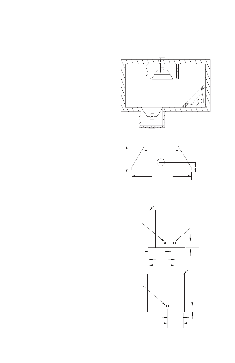
GROUND FLOOR INSTALLATION
Recommended Applications:
• Through the wall using round or square termination
• NOT FOR CORNER INSTALLATION
NOTICE: Do not seal termination
cap to vent pipe. Cap must be
removable for vent inspection
and maintenance.
downward as this may cause
excessive temperatures which
could cause a re. Operation of
improperly installed and maintained venting system could
result in serious injury, property
damage or loss of life.
WARNING: Never run vent
Horizontal High
Wind Square
Termination
(V) Vertical
Minimum
21" 1 ft. 3 ft.
33" 2 ft. 7 ft.
45" 3 ft. 11 ft.
57" 4 ft. 20 ft.
Required
Vertical Pipe
V + H = 40 feet maximum
H = 20 feet maximum
Figure 15 - Horizontal Termination Using One 90° Elbow
(H) Horizontal
Maximum
1' Pipe Min On
Horizontal Run
Wall
Firestop
64" Min. (42")
61" Min. (36")
90° Elbow
H
V + 90· Elbow
1 ft. Min
Before
Elbow
126733-01A 13
www.Astria.US.com

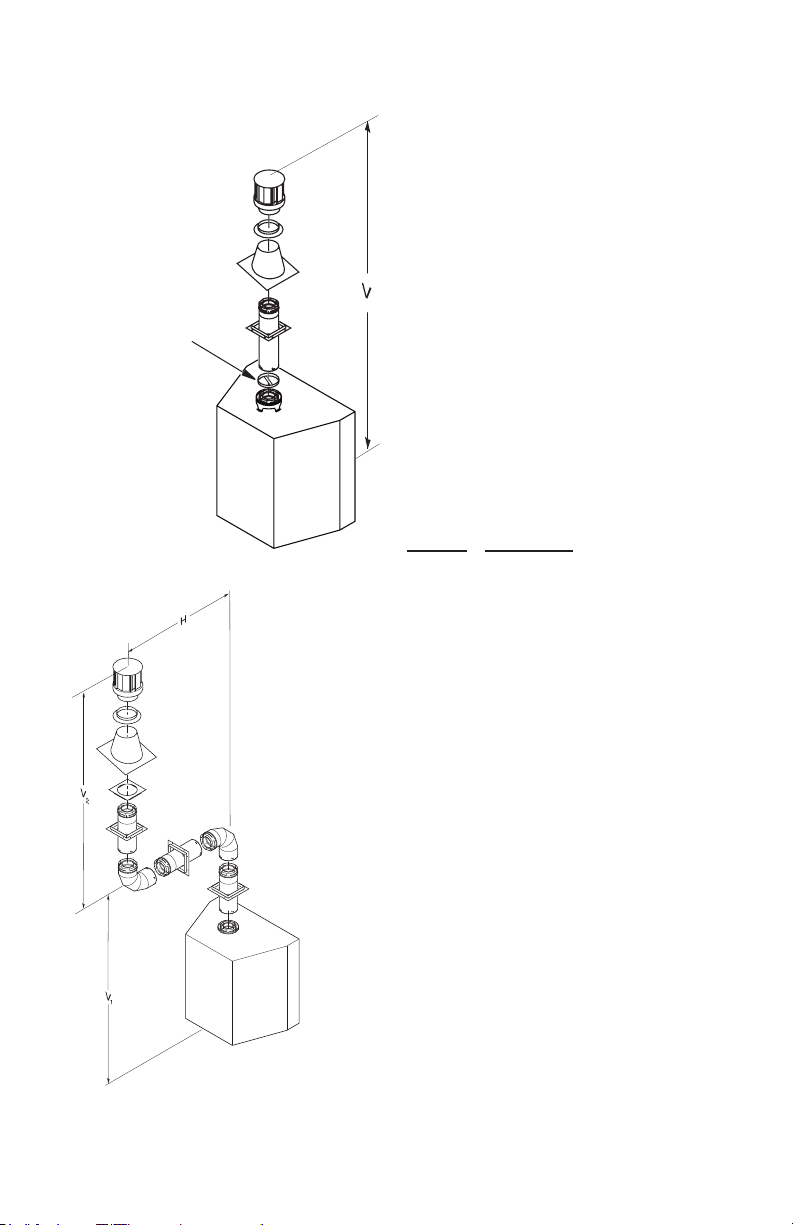
VENTING INSTALLATION
Continued
Venting with Two 90° Elbows
Vertical (V)
Horizontal (H1) +
Horizontal (H2)
6' min. 8' max.
7' min. 10' max.
8' min. 15' max.
20' max. 20' max.
Figure 16 - Horizontal Termination Using Two 90° Elbows
Vertical Termination Installation
Note: Vertical restrictor must be installed in
all vertical installations.
1. Determine route your vertical venting
will take. If ceiling joists, roof rafters or
other framing will obstruct venting system,
consider an offset (see Figure 17) to avoid
cutting load bearing members. Note: Pay
special attention to these installation
instructions for required clearances (air
space) to combustibles when passing
through ceilings, walls, roofs, enclosures,
attic rafters, etc. Do not pack air spaces
with insulation. Also note maximum
vertical rise of venting system and any
maximum horizontal offset limitations.
2. Set replace in desired location. Drop a
plumb line down from ceiling to position
of replace exit ue. Mark center point
where vent will penetrate ceiling. Drill a
small locating hole at this point.
3. Drop a plumb line from inside of roof to
locating hole in ceiling. Mark center point
where vent will penetrate roof. Drill a small
locating hole at this point.
Roof Flashing
Wall Strap
45° Elbow
Ceiling Firestop
Figure 17 - Offset with Wall Strap and 45°
Elbows
www.Astria.US.com
126733-01A14

VENTING INSTALLATION
Continued
Flat Ceiling Installation
1. Cut a 11 1/2" square hole in ceiling using
locating hole as a center point. Opening
should be framed to 11 1/2" x 11 1/2" inside
dimensions, as shown in Figure 10 on
page 11 using framing lumber the same
size as ceiling joists. If area above ceiling is an insulated ceiling or an attic, nail
restop from top side. This prevents loose
insulation from falling into required clearance space. If area above ceiling is a living
space, install restop below framed hole.
Firestop should be installed with no less
than three nails per side (see Figure 15).
2. Assemble desired lengths of pipe and
elbows necessary to reach from replace
ue up through restop. Be sure all pipe
and elbow connections are fully twistlocked (see Figure 9, page 11).
3. Cut a hole in the roof using locating hole
as a center point. (Cover any exposed
open vent pipes before cutting hole in
roof.) The 11 1/2" x 11 1/2" hole must be
measured on the horizontal; actual length
may be larger depending on pitch of roof.
There must be a 1" clearance from vent
pipe to combustible materials. Frame
opening as shown in Figure 10, page 11.
4. Connect a section of pipe and extend up
through hole.
Note: If an offset is needed to avoid
obstructions, you must support vent pipe
every 3 feet. Use wall straps for this purpose (see Figure 17). Whenever possible,
use 45° elbows instead of 90° elbows. The
45° elbow offers less restriction to the ow
of ue gases.
5. Place ashing over pipe section(s) extending through roof. Secure base of
ashing to roof and framing with roong
nails. Be sure roong material overlaps
top edge of ashing as shown in Figure
17. There must be a 1" clearance from
vent pipe to combustible materials.
6. Continue to add pipe sections until height
of vent cap meets the minimum building
code requirements described in Figure 8
on page 8.
Note: You must increase vent height for
steep roof pitches. Nearby trees, adjoining
rooines, steep pitched roofs and other
similar factors may cause poor draft or
down-drafting in high winds. Increasing
vent height may solve this problem.
7. Twist-lock vent cap onto last section of
vent pipe.
Vent Termination Chart
Minimum Height
Roof Pitch Feet Min.
Flat to 6/12 1
6/12 to 7/12 1.25
Over 7/12 to 8/12 1.5
Over 8/12 to 9/12 2
Over 9/12 to 10/12 2.5
Over 10/12 to 11/12 3.25
Over 11/12 to 12/12 4
Over 12/12 to 14/12 5
Over 14/12 to 16/12 6
Over 16/12 to 18/12 7
Over 18/12 to 20/12 7.5
Over 20/12 to 21/12 8.0
Note: If vent pipe passes through any occupied
areas above rst oor, including storage spaces
and closets, you must enclose pipe. You may
frame and sheetrock enclosure with standard
construction material. Make sure and meet the
minimum allowable clearances to combustibles.
Do not ll any required air spaces with insulation.
Vertical Termination Congurations
Figures 19 and 20, page 16, show the congurations for vertical termination.
If area above is an attic or insulated area,
install restop above framed hole.
If area above is a living space, install
restop below framed hole.
Figure 18 - Installing Firestop
126733-01A 15
www.Astria.US.com
VENTING INSTALLATION
Continued
Vertical
Venting
V = 40' max.
Note: Install
Restrictor into
Inner Collar of
Fireplace as
Shown
Figure 19 - Vertical Venting Conguration
Venting with Two 90°
Elbows
Vertical
6' min. 12' max.
7' min. 18' max.
8' min. 20' max.
20' max. 20' max.
V1 + V2 = 40' max.
Figure 20 - Vertical Venting
Conguration Using Two 90° Elbows
Horizontal
(V1)
(H)
www.Astria.US.com
HIGH ALTITUDE INSTALLATION
Your INNOVATIVE HEARTH PRODUCTS
direct vent replace has been tested and approved for elevations from 0-2000 feet.
Fireplaces for high altitude (-HA Models) are
for installations above 4,000 feet only. These
replaces are equipped with parts specic for
higher altitudes.
When installing a non-high altitude replace at
an elevation above 2000 feet, you may need
to decrease the input rating by changing the
existing burner orice to a smaller size. Reduce
input 4% for each 1000 feet above sea level.
Check with your local gas company for proper
orice size identication.
When installing this replace at an elevation
above 4500 feet, check with local authorities.
PARTS LIST FOR VENTING KITS
AND COMPONENTS
IHP (5/8") Pipe & Vent Kits
Number Description
P58-6 6" Section Double Wall Pipe,
Galvanized
P58-12 12" Section Double Wall Pipe,
Galvanized
P58-24 24" Section Double Wall Pipe,
Galvanized
P58-36 36" Section Double Wall Pipe,
Galvanized
P58-48 48" Section Double Wall Pipe,
Galvanized
PA58-712 Adjustable 7"-12" Section Double
Wall Pipe, Galvanized
E58-45 45° Elbow, Galvanized
E58-90 90° Elbow, Galvanized
HTS-58 Horizontal Square Termination,
Galvanized
HHT-58 Horizontal High Wind Round
Termination, Galvanized
VT-58 Vertical Round Termination,
Galvanized
SC-58 Storm Collar, Galvanized
WF-58 Wall Firestop, Galvanized
RF-58-6 Roof Flashing - 0 to 6/12 Pitch,
Galvanized
RF-58-12 Roof Flashing - 6/12 to 12/12 Pitch,
Galvanized
VR-58 Vertical Restrictor, Galvanized
S-58 Vinyl Siding Standoff, Galvanized
WS-58 Wall Strap
CS-58 Cathedral Ceiling Support
FP-58 Firestop Plate
SF-58 Stucco Flashing - For use with
HTS-58
RF-58 Flat Roof Flashing
126733-01A16
FIREPLACE INSTALLATION
CHECK GAS TYPE
Use proper gas type for the replace unit you
are installing. If you have conicting gas types,
do not install replace. See retailer where you
purchased the replace for proper replace
according to your gas type.
INSTALLING GAS PIPING TO
FIREPLACE LOCATION
WARNING: A qualified
service person must connect
replace to gas supply. Follow
all local codes.
CAUTION: For propane/LP
units, never connect replace
directly to the propane/LP sup-
ply. This replace requires an
external regulator (not supplied).
Install the external regulator between the replace and propane/
LP supply.
WARNING: For natural
gas, never connect replace to
private (non-utility) gas wells.
This gas is commonly known
as wellhead gas.
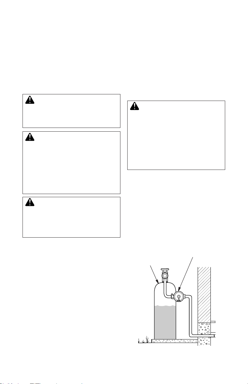
For propane/LP connection only, the installer
must supply an external regulator. The external regulator will reduce incoming gas pressure. You must reduce incoming gas pressure
to between 11" and 14" of w.c. pressure. If
you do not reduce incoming gas pressure,
replace regulator damage could occur. Install
external regulator with the vent pointing down
as shown in Figure 21. Pointing the vent down
protects it from freezing rain or sleet.
CAUTION: Use only new,
black iron or steel pipe. Internally-tinned copper tubing may
be used in certain areas. Check
your local codes. Use pipe of
1/2" diameter or greater to allow
proper gas volume to replace.
If pipe is too small, undue loss
of volume will occur.
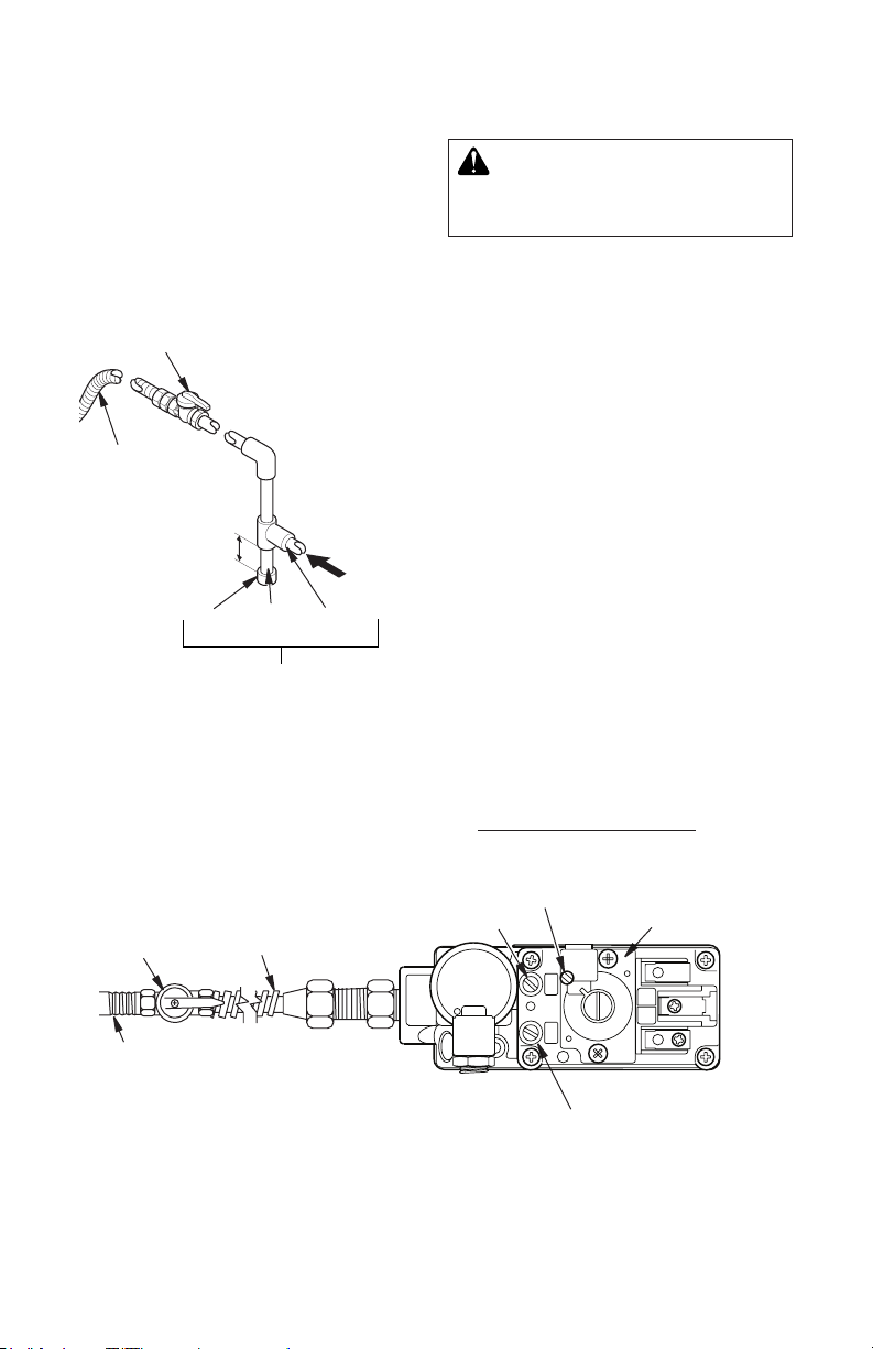
Installation must include an equipment shutoff
valve, union and plugged 1/8" NPT tap. Locate
NPT tap within reach for test gauge hook up.
NPT tap must be upstream from replace (see
Figure 22, page 18).
IMPORTANT: Install main gas valve (equipment shutoff valve) in an accessible location.
The main gas valve is for turning on or shutting
off the gas to the appliance.
Installation Items Needed
Before installing replace, make sure you
have the items listed below.
• external regulator (supplied by installer)
• piping (check local codes)
• sealant (resistant to propane/LP gas)
• equipment shutoff valve *
• test gauge connection *
• sediment trap
• tee joint
• pipe wrench
• approved exible gas line with gas connector (if allowed by local codes)
* An equipment shutoff valve with 1/8" NPT
tap is an acceptable alternative to test gauge
connection. Purchase the equipment shutoff
valve from your retailer.
126733-01A 17
www.Astria.US.com
Propane/LP
Supply Tank
Figure 21 - External Regulator with Vent
Pointing Down (Propane/LP Only)
External Regulator
with Vent Pointing
Down
FIREPLACE INSTALLATION
IN
PILOT
IN
OUT
VENT
TH
TP
TH
TP
Continued
Check your building codes for any special
requirements for locating equipment shutoff
valve to replaces.
Apply pipe joint sealant lightly to male NPT
threads. This will prevent excess sealant from
going into pipe. Excess sealant in pipe could
result in clogged replace valves.
Equipment Shutoff Valve
with 1/8" NPT Tap*
Approved
Flexible
Gas Line
3" Minimum
Cap Pipe Tee
Joint Nipple
Figure 22 - Gas Connection
* The equipment shutoff valve may be supplied with the appliance or you can purchase
it from your retailer.
Natural - From
Gas Meter (5.5"
W.C. to 10.5" W.C.
Pressure)
Propane/LP From
External Regulator
(11" W.C. to 14"
W.C. Pressure)
Sediment Trap/
Drip Leg
WARNING: Use pipe joint
sealant that is resistant to liquid
petroleum (LP) gas.
We recommend that you install a sediment
trap/drip leg in supply line as shown in Figure
22. Locate sediment trap/drip leg where it
is within reach for cleaning. Install in piping
system between fuel supply and replace.
Locate sediment trap/drip leg where trapped
matter is not likely to freeze. A sediment trap
traps moisture and contaminants. This keeps
them from going into replace gas controls. If
sediment trap/drip leg is not installed or is installed wrong, replace may not run properly.
CONNECTING FIREPLACE TO GAS
SUPPLY
Installation Items Needed
• 5/16" hex socket wrench or nut-driver
• sealant (resistant to propane/LP gas, not
provided)
1. Route exible gas line (provided by in-
staller) from equipment shutoff valve to
replace. Route exible gas supply line
through one of the access holes on side
of replace.
2. Attach exible gas line from gas supply to
control valve (see Figure 23).
3. Check all gas connections for leaks. See
Checking Gas Connections, page 19.
Gas Shutoff
Valve
1/2" NPT
Incoming
Gas Line
Flexible
Gas Line
Pilot Adjustment
Outlet Pressure Tap
Red Surface Indicates For
Propane/LP Use Only
Do NOT
Kink
Note:
1) Wire connections not
shown for clarity
Inlet Pressure Tap
2) * 1/8" NPT Plugged
Tapping
Figure 23 - Connecting Incoming Gas Line to Flex Gas Line
www.Astria.US.com
126733-01A18
FIREPLACE INSTALLATION
Continued
CHECKING GAS CONNECTIONS
WARNING: Test all gas piping
and connections, internal and
external to unit, for leaks after
installing or servicing. Correct
all leaks at once.
WARNING: Never use an
open ame to check for a leak.
Apply noncorrosive leak detec-
tion uid to all joints. Bubbles
forming show a leak. Correct all
leaks at once.
PRESSURE TESTING GAS SUPPLY
PIPING SYSTEM
Test Pressures In Excess Of 1/2 PSIG
(3.5 kPa)
1. Disconnect replace and its individual
equipment shutoff valve from gas supply
piping system. Pressures in excess of 1/2
psig (3.5 kPa) will damage replace gas
regulator.
2. Cap off open end of gas pipe where equipment shutoff valve was connected.
3. Pressurize supply piping system by either
opening propane/LP supply tank valve
for propane/LP gas replace or opening
main gas valve located on or near gas
meter for natural gas replace or using
compressed air.
4. Check all joints of gas supply piping system. Apply noncorrosive leak detection
uid to all joints. Bubbles forming show a
leak. Correct all leaks at once.
5. Reconnect fireplace and equipment
shutoff valve to gas supply. Check reconnected ttings for leaks.
Test Pressures Equal To or Less Than
1/2 PSIG (3.5 kPa)
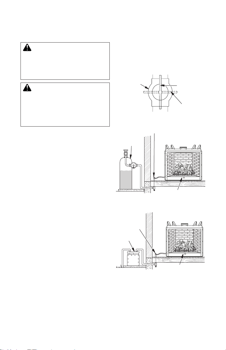
1. Close equipment shutoff valve (see Figure 24).
2. Pressurize supply piping system by either
opening propane/LP supply tank valve
for propane/LP gas replace or opening
main gas valve located on or near gas
meter for natural gas replace or using
compressed air.
126733-01A 19
www.Astria.US.com
3. Check all joints from propane/LP supply
tank or gas meter to equipment shutoff
valve (see Figure 25 or Figure 26). Apply
noncorrosive leak detection uid to all
joints. Bubbles forming show a leak.
4. Correct all leaks at once.
Equipment
Shutoff Valve
Figure 24 - Equipment Shutoff Valve
Equipment
Shutoff Valve
Propane/
LP Supply
Tank
Figure 25 - Checking Gas Joints for
Propane/LP Gas Fireplace
Equipment
Shutoff Valve
Gas Meter
Figure 26 - Checking Gas Joints for
Natural Gas Fireplace
PRESSURE TESTING FIREPLACE GAS
CONNECTIONS
1. Open equipment shutoff valve (see Figure 24).
2. Open propane/LP supply tank valve for
propane/LP replace or main gas valve
located on or near gas meter for natural
gas replace.
Open
Closed
Gas Valve
Gas Valve
FIREPLACE INSTALLATION
Continued
3. Make sure control knob of replace is in
the OFF position.
4. Check all joints from equipment shutoff
valve to gas valve (see Figure 25 or
Figure 26, page 19). Apply noncorrosive
leak detection uid to all joints. Bubbles
forming show a leak. Correct all leaks at
once.
5. Light replace (see Operation, page 25).
Check all other internal joints for leaks.
6. Turn off replace (see To Turn Off Gas to
Appliance, page 25).
REMOVING/REPLACING GLASS
DOOR
CAUTION: Do not operate
this replace with a broken glass
door panel or without the glass
door panel securely in place. For
replacement part information
see Replacement Parts, page 39.
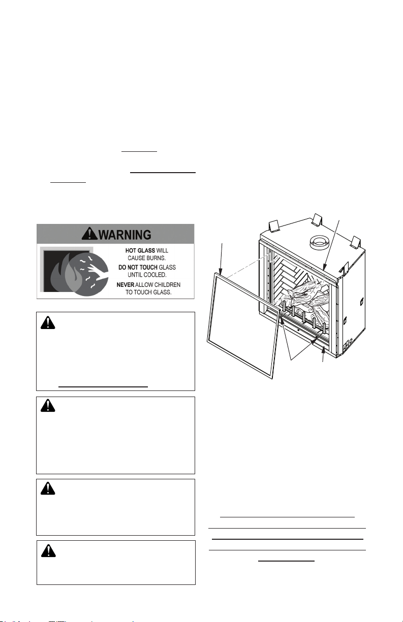
Removing Glass Door
If replacement of glass is necessary, the entire
frame assembly must be replaced. Gloves
must be worn when removing/replacing glass
door. If glass is broken tape remaining glass
onto frame before removing.
1. Remove screens if installed.
2. Open bottom access panel.
3. Unlock 2 door latches on bottom of
rebox.
4. Tilt open glass door 45° from the bottom
of rebox and lift up to release door from
rebox top retainer (see Figure 27).
Door
Retainer
Glass
Door
Door
Latches
Figure 27 - Removing/Replacing Door
Bottom
Access Panel
CAUTION: Wear gloves and
safety glasses while handling
or removing broken glass.
Do not remove if glass is hot.
Keep children and pets away
from glass.
WARNING: If replace has
been running, turn off replace.
Let cool before removing glass
doors.
WARNING: Do not slam or
strike doors. Damage can result
in a hazardous condition.
www.Astria.US.com
Replacing Glass Door
1. Position door frame in front of rebox
opening with bottom of door tilted away
from rebox (see Figure 27).
2. Hook top ange of door frame over top of
rebox frame.
3. Secure 2 bottom door latches.
Discontinue use of the appliance
immediately if doors are damaged and
contact a qualied installer for repair.
Only doors certied with the appliance
shall be used.
126733-01A20
FIREPLACE INSTALLATION
Continued
LAVA ROCK, DECORATIVE GRATE,
EMBER FLAKES AND SCRAP LOG
INSTALLATION
Lava rock, ember akes and scrap log pieces are
included with your replace. Install these items
while glass doors are open and/or removed.
1. Follow instructions from Removing/Re-
placing Glass Door, page 20, to move
glass out of the way of this installation.
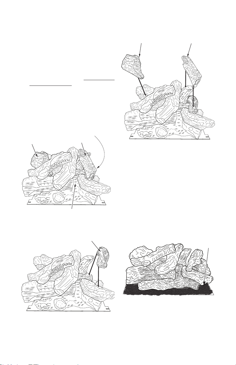
2. For 36" models only: Install 3 loose logs
by placing log #1, log #2 and log #3 onto
one piece log as shown in Figures 28, 28a
and 28b.
Loose Log #1
Underneath Log #2
Loose Log #3
Figure 28 - Installing Loose Logs
Loose Log #2
Glowing Embers
Loose Log #1
Loose Log #3
Figure 28b - Installing Loose Logs #2
and #3
3. Place lava rock around base of burner.
Make sure burner ports are not covered
(see Figure 29).
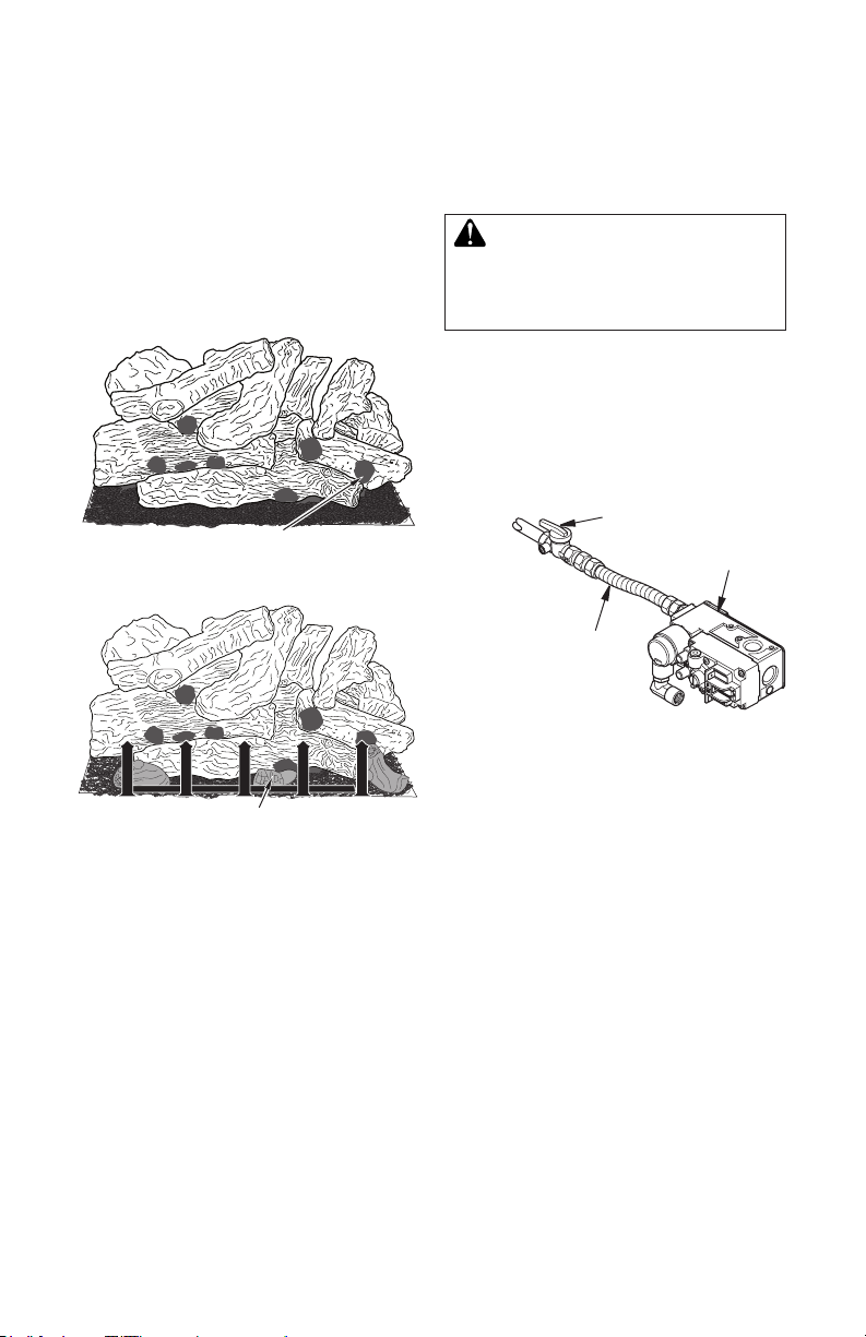
4. Place ember akes around front and sides of
burner and on burner ports (see Figure 30,
page 22). This will create the glowing ember
appearance as the ame touches the ember
akes. Do not block burner ports or pilot ports
by overlapping ember akes in one area. It
is not necessary to use all ember material
provided.
Loose Log #2
Lava Rock
Figure 29 - Installing Lava Rock
Figure 28a - Installing Loose Log #1
126733-01A 21
www.Astria.US.com
FIREPLACE INSTALLATION
Continued
5. Place scrap log pieces randomly behind
grate as shown in Figure 31 on lava rock
and around (but not on) burner ports.
6. Place grate in front of logs as shown in
Figure 31. Be sure grate is balanced so it
does not fall or lean onto logs. Grate does
not attach to hearth assembly.
REMOVING LOG SET/BURNER
MODULE
Connecting and Disconnecting Gas Line
WARNING: A qualied ser-
vice person must connect and
disconnect replace with gas
supply. Follow all local codes.
1. Using a 5/16" hex socket wrench or nutdriver, connect or disconnect exible gas
line and control valve (see Figure 32).
2. After connecting gas line to control valve,
always test for leaks.
Ember Flakes
Figure 30 - Installing Ember Flakes
Scrap Log Pieces
Figure 31 - Installing Scrap Log Pieces
To Gas Supply
(Natural)
To External
Regulator
(Propane/LP)
Flexible Gas
Line, Do NOT
Kink
Figure 32 - Connecting/Disconnecting
Gas Line to Millivolt Valve
Equipment
Shutoff
Valve
Millivolt
Control
Valve
www.Astria.US.com
126733-01A22
FIREPLACE INSTALLATION
Continued
WARNING: Never use an
open ame to check for a leak.
Apply noncorrosive leak de-
tection uid to joints. Bubbles
forming show a leak. Correct
leaks at once.
Burner Base
Log
Assembly
CAUTION: The gas supply
shall be shut off prior to disconnecting the electrical power, if
any, before proceeding with this
installation.
CAUTION: Use gloves when
removing the log set/burner
module from your rebox. Some
metal edges may be sharp. Use
caution with log sets as logs
are fragile.
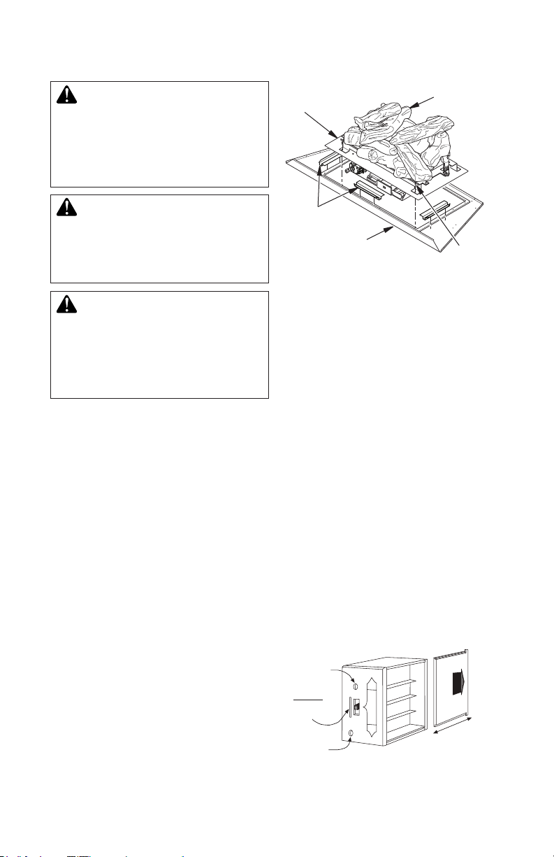
1. Remove glass door (see page 20).
2. Remove grate and all oor media (see
page 22).
3. Carefully lift and remove 3 hearth refractories from replace.
4. Remove 3 spacers from rebox bottom
(see Figure 33).
5. For 36" models only: Remove 3 loose
logs from log set (see Figures 28, 28a,
and 28b, page 21).
6. Remove 9 screws from front and sides of
rebox burner base. Lift entire base from
unit by pulling forward to disengage from rear
ange and then lifting up (see Figure 33).
7. If needed, replace burner gasket before
reinstalling log set/burner module (see
replacement parts list on page 32.)
Spacers
Firebox
Bottom
Screws
Figure 33 - Removing/Installing Burner Base
INSTALLING BATTERIES IN
WIRELESS HAND-HELD REMOTE
CONTROL AND RECEIVER
Installing Batteries in Remote Receiver
1. Open bottom access door.
2. Remove switch plate from receiver.
3. Gently pull receiver from mounting
bracket. The receiver is still connected to
the valve.
4. Remove battery housing cover on remote
receiver to expose battery housing (see
Figure 34).
5. Install 4 AA batteries into housing following positive and negative directions on
battery housing cover removed in step 3
(see Figure 34).
6. Replace battery housing cover, place
back into mounting bracket and cover with
switch plate.
7. Install 2 D batteries into AC backup battery
pack.
8. Close bottom access door.
Requires 4-AA 1.5V
alkaline batteries
Learning
button
Slide
Switch
ON
REMOTE
OFF
Frequency
adjusting
access hole
LEARN
ADJ.
NO
REMOTE
FFO
Remote Receiver
Battery cover slides on/o
Figure 34 - Installing Receiver Batteries
(Included)
126733-01A 23
www.Astria.US.com
FIREPLACE INSTALLATION
REMOTE
OFF
LEARN
ADJ.
Wire terminals
Remote Receiver
Frequency adjusting
access hole
Learning
button
ON
MATCHING SECURITY CODES
Each remote control can use one of 65,536
unique security codes. It may be necessary
to program the remote receiver to "LEARN"
the security code of the remote control upon
initial use, if batteries are replaced or if a replacement remote control is purchased from
your dealer. When matching security codes,
be sure the slide button on the receiver is
in the REMOTE position; the code will not
"LEARN". If the slide switch is in the ON or
OFF position. Program the remote receiver
to "LEARN" a new security code by pushing
the LEARN button on the top of the remote
receiver and then pressing the MODE button on the remote control. A change in the
beeping pattern, at the receiver, indicates the
remote control's code has been programed
into the receiver. When an existing receiver
is matched to a new remote control, the new
security code will override the old one.
The microprocessor that controls the security
code matching procedure is controlled by a
timing function. If you are unsuccessful in
matching the security code on the rst attempt, wait 1-2 minutes before trying again.
This delay allows the microprocessor to reset
its timer circuitry and try up to two or three
more times.
BATTERY LIFE
Life expectancy of the alkaline batteries in the
remote control should be at least 12 months.
Check and replace all batteries annually.
When the remote control no longer operates
the remote receiver from a distance it did previously or the remote receiver does not function at all, the batteries should be checked. It
is important that the remote receiver batteries
are fully charged and provide continuous output voltage of at least 5.3 Volts. The length of
the wire, the more battery power is required to
deliver signals between the remote receiver
and the gas valve. Recommended length is
no longer than 20 feet The remote control
should operate with as little as 9.0 Volts battery power.
Continued
TROUBLESHOOTING
If you encounter problems with your replace
system, the problem may be with the replace
itself or it could be with the remote control.
Review the replace manufacturer's operation manual to make sure all connections are
properly made. Then check the operation of
the remote in the following manner:
• Make sure the batteries are correctly
installed in the receiver. One reversed
battery will keep the receiver from operating properly.
• Check batter in remote control to make
sure contacts are touching (+) and (-)
ends of battery. Bend metal contacts in
for tighter t.
• Be sure receiver and remote control are
within 20 to 25 feet operating range.
• Keep receiver from temperatures ex-
ceeding 130°F. Battery life is shortened
about this level.
• If receiver is installed in tightly enclosed
metal surround, the operating distance
will shorten.
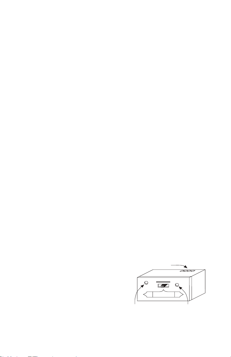
ADJUSTMENTS
• To adjust at the receiver, use a small
slotted screwdriver. Turn the adjustment screw counter-clockwise about 5
degrees or a maximum of 1/8 turn. This
should correct the distance problem.
• If the problem is not corrected, return
adjustment screw to original position and
then turn adjustment screw clockwise.
• This adjustment is like turning your radio
dial. If you keep turning the adjustment
screw, in either direction, you will go past
the proper setting (tuning).
www.Astria.US.com
Figure 35 - Adjusting the Receiver
126733-01A24
OPERATION
FOR YOUR SAFETY
READ BEFORE LIGHTING
WARNING: If you do not fol-
low these instructions exactly,
a re or explosion may result
causing property damage, personal injury or loss of life.
A. This appliance is equipped with an igni-
tion device which automatically lights
the pilot. Do not light pilot by hand.
B. BEFORE LIGHTING smell all around
the appliance area for gas. Be sure to
smell next to the oor because some
gas is heavier than air and will settle
on the oor.
WHAT TO DO IF YOU SMELL GAS
• Do not try to light any appliance.
• Do not touch any electric switch; do
not use any phone in your building.
• Immediately call your gas supplier
from a neighbor's phone. Follow the
gas supplier's instructions.
C. Do not use this appliance if any part
has been under water. Immediately call
a qualied service technician to inspect
the appliance and to replace any part of
the control system and any gas control
which has been under water.
LIGHTING
INSTRUCTIONS
NOTICE: During initial operation
of new replace, burning logs
will give off a paper-burning
smell. Orange ame will also
be present. Open damper or
window to vent smell. This will
only last a few hours.
1. STOP! Read the safety information in
column 1.
2. Turn off all electric power to replace.
3. Turn safety shutoff switch to the OFF
position.
4. Remove center brick/control cover.
5. Turn equipment shutoff valve clockwise
126733-01A 25
to the OFF position (see Figure
36). Do not force.
www.Astria.US.com
6. Wait ve (5) minutes to clear out any gas.
Then smell for gas, including near the
oor. If you smell gas, STOP! Follow “B”
in the safety information. If you don't smell
gas, go to the next step.
7. Turn equipment shutoff valve counterclockwise to the ON position. Do
not force.
8. Replace center brick/control cover.
9. Turn on all electric power to appliance.
10. Turn safety shutoff switch to the ON
position.
11. Visually locate pilot. Ignitor should begin
to spark and main burner should ignite
once ame appears at pilot.
• If lighting appliance for the rst time each
season, it may take several attempts
before supply gas can reach pilot and
main burners.
• If appliance will not stay lit after several
attempts, follow instructions under To
Turn Off Gas To Appliance and call your
service technician or gas supplier.
TO TURN OFF GAS
TO APPLIANCE
1. Turn off safety shutoff switch.
2. Turn off all electric power to appliance if
service is to be performed.
3. Remove center brick/control cover.
4. Turn equipment shutoff valve clockwise
to OFF. Do not force.
5. Replace center brick/control cover.
REMOTE
OPERATION
1. Turn equipment shutoff valve to ON position. You can now turn the burner on and
off with hand-held remote control unit.
IMPORTANT: Be sure to press ON/OFF
buttons on hand-held remote control unit
for up to 3 seconds to assure proper
operation.
2. Press ON/OFF button to turn burner on
and off.

IN
PILOT
IN
OUT
VENT
TH
TP
TH
TP
OPERATION
Continued
Equipment
Shutoff Valve
Figure 36 - Turning Equipment Shutoff Valve to the OFF Position
Ignitor
Sensing Rod
Figure 37 - Pilot
INSPECTING BURNERS
Check pilot ame pattern and burner ame
patterns often.
PILOT ASSEMBLY
The pilot assembly is factory preset for the
proper ame. Alterations may have occurred
during shipping and handling. The pilot is
located on right hand side of burner.
The ame must envelope 1/4" of top of the
ignitor/sensor and grounding stem.
If your pilot assembly does not meet these
requirements:
• Turn the adjustment screw marked PILOT
clockwise to decrease or counterclockwise
to increase the ame to proper size (see
Figure 36). Do not remove the adjustment
screw.
• see Troubleshooting, page 29
Pilot
Burner
Sensing
Rod
Ignitor/
Sensor
Pilot
Burner
Figure 38 - Correct Pilot Flame Pattern
www.Astria.US.com
126733-01A26

INSPECTING BURNERS
Continued
BURNER FLAME PATTERN
Burner ames will be steady, not lifting or oating. Flame patterns will be different from unit
to unit and will vary depending on installation
type and weather conditions.
If the vent conguration is installed incorrectly,
ames will lift or "ghost". This can be dangerous. Inspect ames after installation to ensure
proper installation and performance.
Figure 39 shows a typical ame pattern.
If burner ame pattern differs from that de-
scribed:
• turn replace off (see To Turn Off Gas to
Appliance, page 25)
• see Troubleshooting, page 29
CLEANING AND MAINTENANCE
Figure 39 - Typical Flame Pattern
WARNING: Turn off replace
and let cool before cleaning.
CAUTION: You must keep
control areas, burners and
circulating air passageways of
replace clean. Inspect these
areas of replace before each
use. Have replace inspected
yearly by a qualied service
person. Fireplace may need
more frequent cleaning due to
excessive lint from carpeting,
bedding material, pet hair, etc.
GLASS DOORS
WARNING: Handle glass
door panels with care. Do not
strike, slam or otherwise abuse
glass. Do not operate replace
with the glass door unlatched,
removed, cracked or broken.
WARNING: Do not use
abrasive cleaners as this may
damage glass. Use a nonabrasive household glass cleaner to
clean glass. Do not clean glass
when hot.
Glass must be cleaned periodically. During
start-up it is normal for condensation to form
on the inside of the glass causing lint, dust and
other airborne particles to cling to the glass
surface. During initial start-up a slight lm may
form on the glass due to paint curing. The
glass should be cleaned several times with a
non-ammonia, nonabrasive household cleaner and warm water after the rst two weeks
of operation. Thereafter, clean the glass two
or three times during each heating season,
depending on the usage and circumstances
present. Refer to Removing/Replacing Glass
Door, page 20 of this manual when removing
glass door for cleaning.
126733-01A 27
www.Astria.US.com

CLEANING AND MAINTENANCE
Continued
WARNING: Only parts supplied by the manufacturer
should be used when replacing
broken or damaged glass door
panels (see Replacement Parts,
page 39). Glass door panel are
complete units. No substitute
materials may be used.
CAUTION: Wear gloves and
safety glasses while handling or
removing broken glass. Do not
remove if glass is hot. Keep children and pets away from glass.
If glass has been broken, carefully remove
glass door (see Removing/Replacing Glass
Door, page 20). Vacuum all glass pieces with
a shop vac.
CAUTION: Do not vacuum if
pieces are hot.
Use only glass door replacement intended for
this replace (see Replacement Parts, page
39 for detail on ordering). No substitutions
may be made. See Removing/Replacing
Glass Door, page 20 for instructions for replacing glass doors.
WARNING: Do not operate
replace with glass door unlatched, removed, cracked or
broken.
PILOT AND BURNERS
• Remove material before cleaning burners
and replace when cleaning is complete.
• Burner and controls should be cleaned with
compressed air to remove dust, dirt or lint.
• Use a vacuum cleaner or small, soft bristled
brush to remove excess dust, dirt or lint.
LOGS
• Use a vacuum cleaner to remove any
carbon buildup on logs.
• Replace material periodically as needed.
See Replacement Parts, page 39.
VENTING SYSTEM
Conduct annual inspection of the venting
system following these guidelines:
1. Check areas of venting system that are
exposed to the weather for corrosion (rust
spots or streaks and, in extreme cases,
holes). Have these items replaced immediately by a qualied service person.
2. Remove the vent cap and shine a ash-
light into the vent. Remove any foreign
material.
3. Check for evidence of excessive con-
densation. Continuous condensation can
cause corrosion of caps, pipes and ttings
and can be caused by having excessive
lateral runs, too many elbows or exterior
portions of the system being exposed to
cold weather.
4. Inspect joints to verify that no pipe section
or tting has been disturbed and loosened. Check mechanical supports such
as wall straps for rigidity.
www.Astria.US.com
126733-01A28

TROUBLESHOOTING
WARNING: Turn off replace and let cool before servicing. Only
a qualied service person should service and repair replace.
CAUTION: Never use a wire, needle or similar object to clean
pilot. This can damage pilot unit.
Note: All troubleshooting items are listed in order of operation.
OBSERVED PROBLEM
Ignitor will not spark or pilot
will not light
POSSIBLE CAUSE
1. No gas supply or shutoff
valve is OFF
2. Air in gas line
3. Construction debris clogging pilot orice
4. Low gas pressure
5. Kinked pilot line
6.
Control valve is not opening
7. No power to unit or ignition
module or power transformer is bad
REMEDY
1. Check to see if you have
gas supply and that equipment shutoff valve is
opened
2. Repeat lighting procedure
several times to purge all
air out of lines. If after repeated attempts appliance
does not light, call for qualied service and repair
3. Remove debris and dirt,
inspect and clean any other
possible obstructions
4. Contact your gas supplier
to check pressure
5. Have a qualied technician
replace pilot line
6. Replace control valve (Refer to Replacement Parts,
page 39)
7. Check that main power is
on and that all wire connections are made correctly to
ignition model (see Wiring
Diagram, page 38). Check
for 24 VAC at the secondary side of transformer. If 24
VAC is present and module
does not operate, have
module replaced. Otherwise have transformer replaced
126733-01A 29
www.Astria.US.com

OBSERVED PROBLEM
Pilot will not stay lit
TROUBLESHOOTING
Continued
POSSIBLE CAUSE
1. Loose wiring on ignitor wire
to ignition module and/
or poor ground to ignition
module
2. Pilot ame too low to sense
REMEDY
1. Check wiring connection.
Refer to wiring diagram
(see Wiring Diagram, page
38) and/or check ground
wire to ignition module
2. Clean and adjust pilot burner and check gas supply
and inlet pressure to unit
Note: Have a qualified
technician replace pilot
assembly if broken or corroded
No gas to burner, although
safety shutoff switch and valve
are set to the ON position
Frequent pilot outage
Fireplace produces a clicking/
ticking noise just after burner
is lit or shut off
Slight smoke or odor during
initial operation
1. Safety shutoff switch wires
defective or too long
1. Pilot ame may be too low,
causing safety pilot to “drop
out”
2. Improper venting or excessive blockage
1. Metal expanding while
heating or contracting while
cooling
1. Residues from manufacturing processes and logs
curing
1. Check electrical connections
1. Clean and adjust pilot ame
for maximum flame impingement on thermopile
2. Have vent system inspected, including termination
cap. Remove any restriction
or obstruction
1. This is normal with most
replaces. If noise is excessive, contact qualied
service person
1. Problem will stop after a few
hours of operation
www.Astria.US.com
126733-01A30

TROUBLESHOOTING
Continued
WARNING: If you smell gas
• Shut off gas supply.
• Do not try to light any appliance.
• Do not touch any electrical switch; do not use any phone in your
building.
• Immediately call your gas supplier from a neighbor’s phone. Follow the gas supplier’s instructions.
• If you cannot reach your gas supplier, call the re department.
OBSERVED PROBLEM
Gas odor even when gas
control valve is off
Gas odor during combustion
Glass soots
Dark residue on logs or inside
of replace
POSSIBLE CAUSE
1. Gas leak. See Warning
statement at top of page
2. Control valve defective
1. Foreign matter between
control valve and burner
2. Gas leak. See Warning
statement at top of page
1. Debris around burner air
mixer
2. Improper vent conguration
1. Air holes at burner inlet
blocked
2. Burner ame holes blocked
3. Improper venting or excessive blockage
4. Excessive amounts of embers and pan material
REMEDY
1. Locate and correct all leaks
(see Checking Gas Connections, page 19)
2. Replace control valve
1. Take apart gas tubing and
remove foreign matter
2. Locate and correct all leaks
(see Checking Gas Connections, page 19)
1. Inspect opening at base of
burner to see that it is NOT
packed with any type of
material
2. Check vent configuration
specication (see Venting
Installation, page 10)
1. Clean out air holes at burner inlets. Periodically repeat
as needed
2. Remove blockage
3. Have vent system inspected, including termination
cap. Remove any restrictions or obstruction
4. Clear excess embers until
a minimum gap of 1/2"
remains under grate
126733-01A 31
www.Astria.US.com
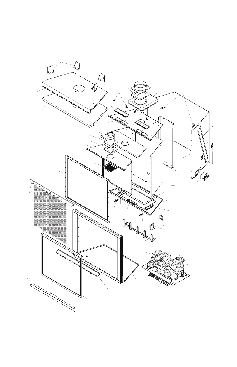
PARTS
29
MODELS SENTINEL36TEN, SENTINEL36TEP, SENTINEL42TEN AND
SENTINEL42TEP
24
23
31
30
16
15
14
13
20
19
18
21
28
3
38
37
12
5
4
32
33(36")
8
32(42")
8
7
36
3
2
1
6
25
27
22
26
17
11
10
32
9
35
34
www.Astria.US.com
126733-01A32

This list contains replaceable parts used in your replace. When ordering parts, follow the
PARTS
instructions listed under Replacement Parts on page 39 of this manual.
KEY
NO. PART NO. DESCRIPTION QTY.
1 122653-01 Door Assembly, 36" • • 1
122653-02 Door Assembly, 42" • • 1
2 122950-02 Bottom Door Assembly, 36" • • 1
122950-01 Bottom Door Assembly, 42" • • 1
3 121301-01 Face Assembly, 36" • • 1
121301-02 Face Assembly, 42" • • 1
4 122952-02 Screen Door Kit, 36" • • 1
122952-01 Screen Door Kit, 42" • • 1
5 ** Firebox Face • • • • 1
6 122842-03 Hearth Assembly, 36" NG • 1
122842-04 Hearth Assembly, 36" Propane/LP • 1
122842-01 Hearth Assembly, 42" NG • 1
122842-02 Hearth Assembly, 42" Propane/LP • 1
123781-01 Hearth Assembly, 36" NG, High Altitude 1
123781-02 Hearth Assembly, 42" NG, High Altitude 1
7 123210-01 Grate, 36" • • 1
123210-02 Grate, 42" • • 1
8 122652-01 Door Latch • • • • 2
9 ** Firebox Leg • • • • 4
10 ** Firebox Bottom • • • • 1
11 121431-01 Gasket, 36" • • 1
111913-02 Gasket, 42" • • 1
12 122919-01 Draft Diverter • • • • 1
13 ** Air Exchange • • • • 1
14 ** 5" Gasket • • • • 1
15 ** 5" Inner Connector • • • • 1
16 ** A/E Insulation • • • • 1
17 ** Firebox Surround • • • • 1
18 ** Firebox Top • • • • 1
19 ** Relief Assembly • • • • 2
20 ** Relief Bracket • • • • 4
21 ** Top Plenum • • 1
22 ** Rear Plenum • • 1
23 ** 5" Gasket • • • • 1
24 ** Connector, 8" x 3.25" • • • • 1
25 121295-01 36" Fireplace Surround • • 1
121302-01 42" Fireplace Surround • • 1
26 110037-01 Electrical Duct Assembly • • • • 1
27 117891-01 Fireplace Handle • • • • 4
28 120520-01 Refractory Retainer • • • • 3
29 20280 Top Spacer • • • • 4
30 ** Top Insulation • • • • 1
31 ** Fireplace Top • • 1
32 ** Hearth Side Spacer • • • • 2,3
33 ** Hearth Front Spacer • • 1
34 123182-01 Log #1 • • • • 1
35 123181-01 Log #2 • • 1
36 123211-01 Log #3 • • 1
37 125104-01 Draft Shield 36" • • 1
125104-02 Draft Shield 42" • • 1
38 109720-03 Spacer Clearance • • • • 3
**Not a eld replaceable part.
126733-01A 33
www.Astria.US.com
Sentinel36TEP
Sentinel36TEN
Sentinel42TEP
Sentinel42TEN
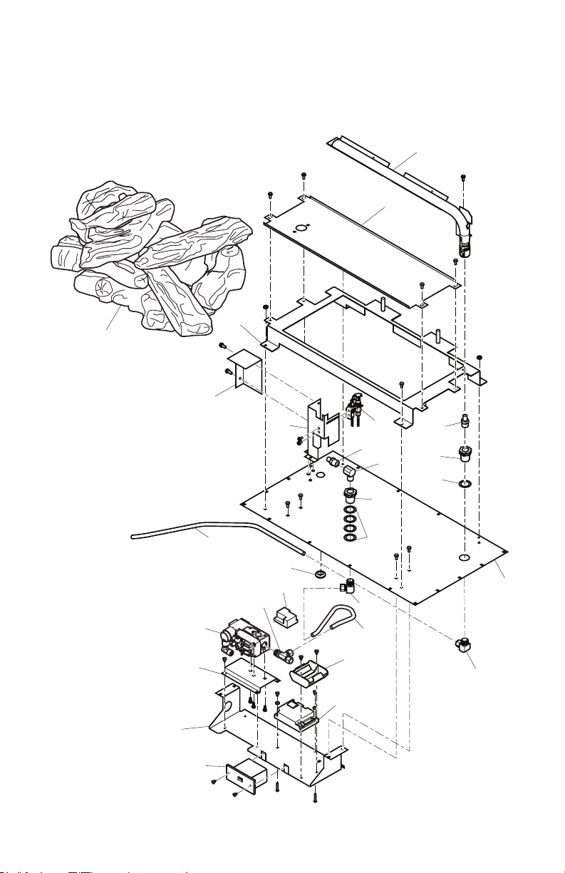
PARTS
BURNER ASSEMBLY MODELS SENTINEL36TEN, SENTINEL36TEP,
SENTINEL42TEN AND SENTINEL42TEP
1
2
6
24
8
22
25
15
17
23
www.Astria.US.com
18
16
12
20
19
21
13
10
14
7
9
4
5
3
4
5
11
13
126733-01A34

PARTS
BURNER ASSEMBLY
This list contains replaceable parts used in your replace. When ordering parts, follow the
instructions listed under Replacement Parts on page 39 of this manual. This table uses catalog
numbers for clarity on models.
KEY
NO. PART NO. DESCRIPTION QTY.
1 122839-02 Burner Tube, 36" • • 1
122839-01 Burner Tube, 42" • • 1
2 ** Front Burner Assembly • • • • 1
3 112371-15 Rear Orice, #47 NG • 1
23100 Rear Orice, #56 Propane/LP • 1
23101 Rear Orice, #44 NG • 1
23567 Rear Orice, #55 Propane/LP • 1
4 11214 Bulkhead Fitting • • • • 2
5 116573-01 Washer, Flt 7/8"x11/4" OD • • • • 5
6 ** Log/Burner Base • • • • 1
7 122122-01 Pilot, NG • • 1
122122-02 Pilot, Propane/LP • • 1
123783-01 Pilot, NG High Altitude 1
8 ** Pilot Shield • • • • 1
9 14296 Elbow, Street 3/8" • • • • 1
10 112371-15 Front Orice, #47 NG • 1
23100 Front Orice, #56 Propane/LP • 1
24771 Front Orice, #42 NG • 1
23100 Front Orice, #56 Propane/LP • 1
11 ** Base • • • • 1
12 114027-01 Grommet SC 1/2" ID 1 1/16" OD • • • • 1
13 14399 90° Elbow, Brass 3/8" Tube x 3/8" NPT • • • • 2
14 111817-06 Flextube Dormont, 3/8" Dia. x 11" • • • • 1
15 111817-09 Flextube Dormont, 3/8" Dia. x 24" • • • • 1
16 ** Pilot Bracket • • • • 1
17 122116-01 Dexen Valve, NG • • 1
122117-01 Dexen Valve, LP • • 1
123782-01 Dexen Valve, NG High Altitude 3.8" 1
18 112823-01 Brass T-Fitting 3/8" • • • • 1
19 122118-01 Control Module • • • • 1
20 122119-01 Battery Relay • • • • 1
21 122121-01 Battery Pack • • • • 1
22 122860-01 Valve Bracket • • • • 1
23 125243-01 Remote Control Kit • • • • 1
24 ** Log Assembly, 36" • • 1
** Log Assembly, 42" • • 1
25 123560-01 Base Valve • • • • 1
PARTS AVAILABLE NOT SHOWN
122120-01 Wire Harness Relay • • • • 1
122123-01 AC Adapter 3V • • • • 1
112799-01 Ember Flakes Kit • • • • 1
26839 Rockwool • • • • 1
GA6060 Lave Rock Kit • • • • 1
VTA-LS5-2 Log Scrap Kit • • • • 1
14253 30" Flex Line • • • • 1
F1579/F1580
F1577/F1578
F1581/F1582
F1583/F1584
126733-01A 35
www.Astria.US.com
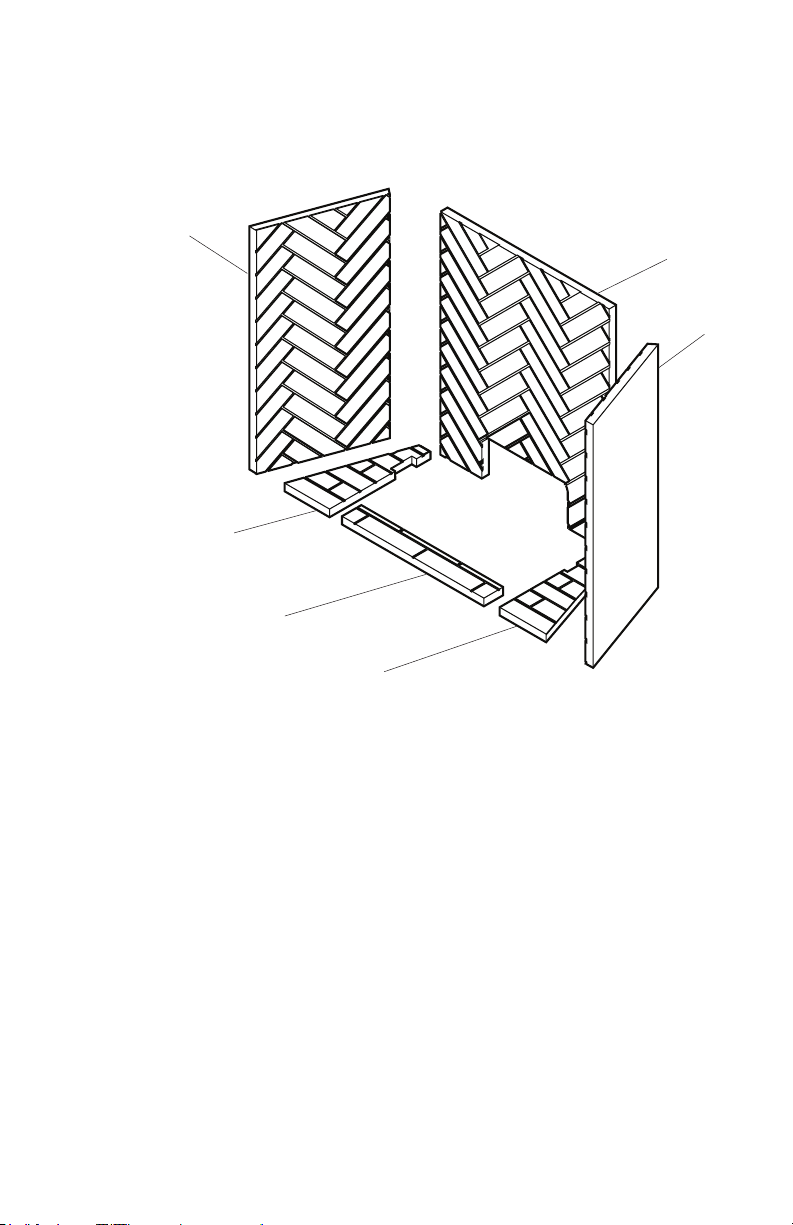
REFRACTORY PARTS
2
PARTS
1
Herringbone
Brick Shown
3
4
5
6
www.Astria.US.com
126733-01A36

PARTS
REFRACTORY PARTS
KEY
NO. PART NO. DESCRIPTION QTY.
1 125124-01 Rear Refractory, Herringbone 42" White 1
125124-02 Rear Refractory, Herringbone 42" Red • 1
125088-01 Rear Refractory, Herringbone 36" White 1
125088-02 Rear Refractory, Herringbone 36" Red • 1
125123-01 Rear Refractory, Stacked 42" White 1
125123-02 Rear Refractory, Stacked 42" Red • 1
125087-01 Rear Refractory, Stacked 36" White 1
125087-02 Rear Refractory, Stacked 36" Red • 1
2 125126-01 Left Refractory, Herringbone 42" White 1
125126-02 Left Refractory, Herringbone 42" Red • 1
125090-01 Left Refractory, Herringbone 36" White 1
125090-02 Left Refractory, Herringbone 36" Red • 1
125125-01 Left Refractory, Stacked 42" White 1
125125-02 Left Refractory, Stacked 42" Red • 1
125089-01 Left Refractory, Stacked 36" White 1
125089-02 Left Refractory, Stacked 36" Red • 1
3 125128-01 Right Refractory, Herringbone 42" White 1
125128-02 Right Refractory, Herringbone 42" Red • 1
125092-01 Right Refractory, Herringbone 36" White 1
125092-02 Right Refractory, Herringbone 36" Red • 1
125127-01 Right Refractory, Stacked 42" White 1
125127-02 Right Refractory, Stacked 42" Red • 1
125091-01 Right Refractory, Stacked 36" White 1
125091-02 Right Refractory, Stacked 36" Red • 1
4 125129-01 Left Front Refractory 42" White 1
125129-02 Left Front Refractory 42" Red • • 1
125093-01 Left Front Refractory 36" White 1
125093-02 Left Front Refractory 36" Red • • 1
5 125131-01 Center Front Refractory 42" White 1
125131-02 Center Front Refractory 42" Red • • 1
125095-01 Center Front Refractory 36" White 1
125095-02 Center Front Refractory 36" Red • • 1
6 125130-01 Right Front Refractory 42" White 1
125130-02 Right Front Refractory 42" Red • • 1
125094-01 Right Front Refractory 36" White 1
125094-02 Right Front Refractory 36" Red • • 1
F1581/F1583
F1577/F1579
F1582/F1584
F1578/F1580
126733-01A 37
www.Astria.US.com
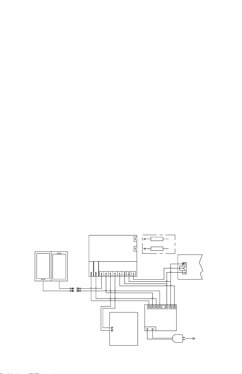
SPECIFICATIONS
SENTINEL36TEN
• Rating: 33,500 Btu/hr
• Gas Type: Natural Gas Only
• Ignition: Electronic
• Manifold Pressure: 3.5" w.c.
• Minimum Inlet Supply Pressure: 5" w.c.
• Maximum Inlet Supply Pressure: 10.5" w.c.
• Front Orice: #47
• Rear Orice: #47
SENTINEL42TEN
• Rating: 41,000 Btu/hr
• Gas Type: Natural Gas Only
• Ignition: Electronic
• Manifold Pressure: 3.5" w.c.
• Minimum Inlet Supply Pressure: 5" w.c.
• Maximum Inlet Supply Pressure: 10.5" w.c.
• Front Orice: #42
• Rear Orice: #44
SENTINEL36TEP
• Rating: 31,000 Btu/hr
• Gas Type: Propane/LP Gas Only
• Ignition: Electronic
• Manifold Pressure: 10" w.c.
• Minimum Inlet Supply Pressure: 11" w.c.
• Maximum Inlet Supply Pressure: 13" w.c.
• Front Orice: #56
• Rear Orice: #56
SENTINEL42TEP
• Rating: 37,000 Btu/hr
• Gas Type: Propane/LP Gas Only
• Ignition: Electronic
• Manifold Pressure: 10.0" w.c.
• Minimum Inlet Supply Pressure: 11" w.c.
• Maximum Inlet Supply Pressure: 13" w.c.
• Front Orice: #56
• Rear Orice: #55
BATTERY PACK
SIZE
"D"
SIZE
"D"
Red
WIRING DIAGRAM
I
S
CONTROL MODULE
Yl GnBn BkOgBkBk Bn
Bu
Bu
Bk
Red
Bk
REMOTE
RECIEVER
Bn
4 "AA" SIZE
BATTERY
www.Astria.US.com
IS
PILOT CONNECTORS
RedBuYlBu BkOgGn
BATTERY
RELAY
ADAPTER
VALV E
THTP
TP
TH
TO J-BOX
126733-01A38

REPLACEMENT PARTS
Note: Use only original replacement parts.
This will protect your warranty coverage for
parts replaced under warranty.
Contact authorized dealers of this product.
If they can’t supply original replacement
part(s), call INNOVATIVE HEARTH PRODUCTS at 1-800-655-2008.
When calling, have ready:
• your name
• your address
• model and serial numbers of your replace
• how replace was malfunctioning
• purchase date
Usually, we will ask you to return the part to
the factory.
TECHNICAL SERVICE
You may have further questions about installation, operation, or troubleshooting. If so,
contact INNOVATIVE HEARTH PRODUCTS
at 1-800-655-2008. When calling please
have your model and serial numbers of your
replace ready.
You can also visit our web site at
www.IHP.US.com.
ACCESSORIES
Purchase these accessories from your local
dealer. If they can not supply these accessories
call INNOVATIVE HEARTH PRODUCTS at
1-800-655-2008 for information. You can also
write to the address listed on the back page
of this manual.
Brick Perimeter Trim Kit
PBS36 - Red
VPBS36 - Ivory
PBS42 - Red
VPBS42 - Ivory
Magnetic attachment, Matching refractory
brick facing surround kit.
SERVICE HINTS
When Gas Pressure Is Too Low
• pilot will not stay lit
• burners will have delayed ignition
• replace will not produce specied heat
• propane/LP gas supply might be low (propane/LP units only)
You may feel your gas pressure is too low. If
so, contact your local gas supplier.
Propane/Natural Gas Conversion Kit
IMPORTANT: NOT to be used for High Altitude
(-HA) Models
PCD-36S - Propane/LP Gas Conversion Kit
NCD-36S - Natural Gas Conversion Kit
PCD-42S - Propane/LP Gas Conversion Kit
NCD-42S - Natural Gas Conversion Kit
Dual Blower Kit
LPDBK
Remote Control Kit - WRC Series
Standard ON/OFF electronic remote control
kit.
Ledgestone Refractory Liner Kit
BLY36STL
BLY42STL
126733-01A 39
www.Astria.US.com

Innovative Hearth Products
Astria™ Brand Gas Fireplace
Limited Lifetime Warranty
THE WARRANTY
Innovative Hearth Products ("IHP") Limited Lifetime Warranty warrants your Astria™ brand gas fireplace ("Product") to be free from defects in materials and workmanship at
the time of manufacture. The Product body and firebox carry the Limited Lifetime Warranty. Ceramic glass carries the Limited Lifetime Warranty against thermal breakage
only. After installation, if covered components manufactured by IHP are found to be defective in materials or workmanship during the Limited Lifetime Warranty period and
while the Product remains at the site of the original installation, IHP will, at its option, repair or replace the covered components. If repair or replacement is not commercially practical, IHP will, at its option, refund the purchase price or wholesale price of the IHP product, whichever is applicable. IHP will also pay IHP prevailing labor rates,
as determined in its sole discretion, incurred in repairing or replacing such components for up to five years. THERE ARE EXCLUSIONS AND LIMITATIONS to this Limited
Lifetime Warranty as described herein.
COVERAGE COMMENCEMENT DATE
Warranty coverage begins on the date of installation. In the case of new home construction, warranty coverage begins on the date of first occupancy of the dwelling or six
months after the sale of the Product by an independent IHP dealer/distributor, whichever occurs earlier. The warranty shall commence no later than 24 months following
the date of product shipment from IHP, regardless of the installation or occupancy date.
EXCLUSIONS AND LIMITATIONS
This Limited Lifetime Warranty applies only if the Product is installed in the United States or Canada and only if operated and maintained in accordance with the printed
instructions accompanying the Product and in compliance with all applicable installation and building codes and good trade practices.
This warranty is non-transferable and extends to the original owner only. The Product must be purchased through a listed supplier of IHP and proof of purchase must be
provided. The Product body and firebox carry the Limited Lifetime Warranty from the date of installation. Vent components, trim components and paint are excluded from
this Limited Lifetime Warranty. The following do not carry the Limited Lifetime Warranty but are warranted as follows:
Burner – Repair or replacement for five years from the date of installation
Gas components & electrical components – Repair or replacement for one year from the date of installation
Gaskets – Repair or replacement for one year from the date of installation
Gold & nickel plating - Replacement for two years from date of installation. Excludes tarnishing
Labor coverage – Prevailing IHP labor rates apply for the warranty period of the component
Light bulbs & batteries – Replacement for 90 days from the date of installation
Logs – Replacement for five years from the date of installation against thermal breakage only
Optional blowers & remote controls – Repair or replacement for one year from the date of installation
Optional glass doors & optional glass accessories – Repair or replacement for 90 days from the date of installation
Optional surrounds – Stone/Natural Materials: Replacement for one year against cracking or breakage due to thermal stress. Other Materials: Replacement for one
year. Excludes surface and hairline cracks and scratches or slight color changes that do not affect the operation or safety of the unit
Tempered Glass -Replacement for one year from the date of installation
Parts not otherwise listed carry a 90 day warranty from the date of installation.
Whenever practicable, IHP will provide replacement parts, if available, for a period of 10 years from the last date of manufacture of the Product.
IHP will not be responsible for: (a) damages caused by normal wear and tear, accident, riot, fire, flood or acts of God; (b) damages caused by abuse, negligence, misuse, or
unauthorized alteration or repair of the Product affecting its stability or performance (The Product must be subjected to normal use. The Product is designed to burn either
natural or propane gas only. Burning conventional fuels such as wood, coal or any other solid fuel will cause damage to the Product, will produce excessive temperatures
and could result in a fire hazard.); (c) damages caused by failing to provide proper maintenance and service in accordance with the instructions provided with the Product;
(d) damages, repairs or inefficiency resulting from faulty installation or application of the Product.
IHP is not responsible for inadequate fireplace system draft caused by air conditioning and heating systems, mechanical ventilation systems, or general construction conditions
which may generate negative pressure in the room in which the appliance is installed. Additionally IHP assumes no responsibility for drafting conditions caused by venting
configurations, adjoining trees or buildings, adverse wind conditions or unusual environmental factors and conditions that affect the operation of the unit.
This Limited Lifetime Warranty covers only parts and labor as provided herein. In no case shall IHP be responsible for materials, components or construction, which are not
manufactured or supplied by IHP or for the labor necessary to install, repair or remove such materials, components or construction. Additional utility bills incurred due to
any malfunction or defect in equipment are not covered by this warranty. All replacement or repair components will be shipped F.O.B. from the nearest stocking IHP factory.
LIMITATION ON LIABILITY
It is expressly agreed and understood that IHP’s sole obligation and the purchaser’s exclusive remedy under this warranty, under any other warranty, expressed or implied,
or in contract, tort or otherwise, shall be limited to replacement, repair, or refund, as specified herein.
In no event shall IHP be liable for any incidental or consequential damages caused by defects in the Product, whether such damage occurs or is discovered before or after
repair or replacement, and whether such damage is caused by IHP’s negligence. IHP has not made and does not make any representation or warranty of fitness for a particular
use or purpose, and there is no implied condition of fitness for a particular use or purpose.
IHP makes no expressed warranties except as stated in this Limited Lifetime Warranty. The duration of any implied warranty is limited to the duration of this expressed warranty.
No one is authorized to change this Limited Lifetime Warranty or to create for IHP any other obligation or liability in connection with the Product. Some states and provinces
do not allow the exclusion or limitation of incidental or consequential damages, so the above limitations or exclusions may not apply to you. The provisions of this Limited
Lifetime Warranty are in addition to and not a modification of or subtraction from any statutory warranties and other rights and remedies provided by law.
INVESTIGATION OF CLAIMS AGAINST WARRANTY
IHP reserves the right to investigate any and all claims against this Limited Lifetime Warranty and to decide, in its sole discretion, upon the method of settlement.
To receive the benefits and advantages described in this Limited Lifetime Warranty, the appliance must be installed and repaired by a licensed contractor approved by IHP.
Contact IHP at the address provided herein to obtain a listing of approved dealers/distributors. IHP shall in no event be responsible for any warranty work done by a
contractor that is not approved without first obtaining IHP's prior written consent.
HOW TO REGISTER A CLAIM AGAINST WARRANTY
In order for any claim under this warranty to be valid, you must contact the IHP dealer/distributor from which you purchased the product. If you cannot locate the dealer/
distributor, then you must notify IHP in writing. IHP must be notified of the claimed defect in writing within 90 days of the date of failure. Notices should be directed to the
IHP Warranty Department at 1508 Elm Hill Pike, Suite 108, Nashville, TN 37210 or visit our website at WWW.ASTRIA.US.COM.
Printed in U.S.A. © 2013 Innovative Hearth Products LLC
P/N 900199-00, Rev. NC 12/2013
Innovative Hearth Products
1508ElmHillPike,Suite108•Nashville,TN37210

KEEP THIS WARRANTY
Model (
located on product or identication tag
Serial No. (
located on product or identication tag
Date Purchased __________________________
Keep receipt for warranty verication.
) _____________________________
) __________________________
126733-01A 41
www.Astria.US.com

NOTES

NOTES
126733-01A 43
www.Astria.US.com

P126733-01
1508 Elm Hill Pike, Suite 108
Nashville, TN 37210
1-800-655-2008
www.IHP.US.com
126733-01
Rev. A
1/14
 Loading...