

Page 1

Installation and Operation Instructions
PFS
Astria™ Wood-Burning Residential
and Outdoor Fireplace
P/N 126767-01 Rev. A 01/2014
P126767-01
Models
®
CAT36P2 CAT36P3
USC
SAVE THIS BOOK
This book is valuable. In addition to instructing you on how to install and maintain your appliance, it also contains
information that will enable you to obtain replacement parts or accessory items when needed. Keep it with your other
important papers.
INSTALLER: Leave this manual with the appliance.
CONSUMER: Retain this manual for future reference.
This wood burning fireplace complies with
UL127 CAN/ULC-S610-M87 standard as a
FACTORY BUILT FIREPLACE.
This fireplace is approved for use as a wood furning fireplace or for use with a vented gas log approved to
ANSI Z21.60 or Z21.84 standards or for use with a vent-free gas log heater approved to ANSI Z21.11.2 standard.
FOR CANADA: The authority having jurisdiction
(such as the municipal building department, fire
f i r e - p a r t s . c o m
department, etc.) should be contacted before
installation to determine the need to obtain a
permit.
This appliance may be installed in an aftermarket permanently located, manufactured home (USA only)
or mobile home, where not prohibited by local codes. This appliance is only for use with the type of gas indicated
on the rating plate. This appliance is not convertible for use with other gases, unless a certified kit is used.
WARNING: If the information in these
instructions is not followed exactly, a fire or
explosion may result causing property damage,
personal injury or death.
Installateur : Laissez cette notice avec l’appareil.
Consommateur : Conservez cette notice pour consultation ultérieure.
Ce foyer au bois est conforme aux UL 127 CAN/ULCS610-M87 norme comme une USINE CONSTRUITE
CHEMINÉE.
POUR LE CANADA: L’autorité compétente (comme le
service municipal du bâtiment, les pompiers, etc.) doit
être contacté avant l’installation afin de déterminer la
nécessité d’obtenir un permis.
AVERTISSEMENT : Assurez-vous de bien suivre les
instructions données dans cette notice pour réduire au
minimum le risque d’incindie ou d’explosion ou pour éviter
tout dommage matériel, toute blessure ou la mort.
— Do not store or use gasoline or other
flammable vapors and liquids in the vicinity
of this or any other appliance.
— WHAT TO DO IF YOU SMELL GAS:
• Do not try to light any appliance.
• Do not touch any electrical switch; do not
use any phone in your building.
• Immediately call your gas supplier from
a neighbor’s phone. Follow the gas
supplier’s instructions.
• If you cannot reach your gas supplier, call
the fire department.
— Installation and service must be performed
by a qualified installer, service agency or the
gas supplier.
— Ne pas entreposer ni utilizer d’essence ni d’autres
vapeurs ou liquides inflammables dans le voisinage
de cet appareil ou de tout autre appareil.
— QUE FAIRE SI VOUS SENTEZ UNE ODEUR DE GAZ :
• Ne pas tenter d’allumer d’appareil.
• Ne touchez à aucan interrupteur. Ne pas vous
servir des téléphones se trouvant dans le bâtiment
où vous trouvez.
• Appelez immédiatement votre fournisseur de
gaz depuis un voisin. Suivez les instructions du
fournisseur.
• Si vous ne pouvez rejoindre le fournisseur de gaz,
appelez le service des incindies.
— L’installation et l’entretien doivent être assurés par un
installateur ou un service d’entretien qualifié ou par
le fournisseur de gaz.
Page 2

These models meet the EPA Wood Burning Fireplace
Program Phase 2 emission level. NOTE: To ensure proper
replace operation, the catalyst should be replaced at a
minimum of 3 years and a maximum of 5 years.
SAVE THIS BOOK
This book is valuable. In addition to instructing you
on how to install and maintain your appliance, it also
contains information that will enable you to obtain replacement parts or accessory items when needed. Keep
it with your other important papers.
CATALYTIC FIREPLACE
CAT36P2 AND CAT36P3
36" WOOD BURNING OUTDOOR
FIREPLACE
For more information, visit www.Astria.US.com
CATALYTIC FIREPLACE OWNER’S
OPERATION AND INSTALLATION MANUAL
PFS
®
USC
This replace is approved for use as a wood burning replace or for use with a vented gas log approved to ANS
Z21.60 and Z21.84 standards or for use with a vent-free gas
log heater approved to ANS Z21.11.2 standard. A INNOVA-
TIVE HEARTH PRODUCTS hood must be installed when
using a vent-free log heater (see Accessories, page 21).
This wood burning replace complies with UL127CAN/ULC-S610-M87 standard as a FACTORY BUILT
FIREPLACE.
FOR CANADA: The authority having jurisdiction (such
as the municipal building department, re department,
etc.) should be contacted before installation to determine the need to obtain a permit.
INSTALLER: Leave this manual with the appliance.
CONSUMER: Retain this manual for future reference.
f i r e - p a r t s . c o m
Page 3

SAFETY
WARNING: Do not install a
replace insert in this box unless
the manufacturer's instructions
with the insert specically state
this replace has been tested for
use with this insert.
FOR YOUR SAFETY
• Do not store or use gasoline
or any other ammable vapors
or liquids in the vicinity of this
or any other appliance.
• Due to high temperatures, the
appliance should be located
out of trafc and away from
furniture and draperies.
• Do not place clothing or other
ammable materials on or near
the appliance.
• Never leave children unattended when a re is burning
in the replace.
WARNING: Use solid wood
or processed solid fuel re logs
only. When processed wood
fuel re logs are used, do not
poke or stir the logs while they
are burning. Use only re logs
that have been evaluated for
the application in replace and
refer to re log warnings and
caution markings on packaging
prior to use.
This replace is not intended to
be used as a substitute for a fur-
nace to heat an entire home. Use
for supplemental heat only.
WARNING: Improper instal-
lation, adjustment, alteration,
service or maintenance can
cause injury, property damage or
loss of life. Refer to this manual
for assistance or additional in-
formation. Consult a qualied
installer or local distributor.
IMPORTANT: Check local codes
before installing this replace.
Before beginning installation of this replace,
read these instructions through completely.
• This INNOVATIVE HEARTH PRODUCTS
fireplace and its components are safe
when installed according to this installation
manual. Unless you use IHP components,
which have been designed and tested for
the replace system, you may cause a re
hazard.
• The INNOVATIVE HEARTH PRODUCTS
warranty will be voided by and IHP disclaims any responsibility for the following
actions.
a. Modification of the fireplace, com-
ponents, doors, air inlet system and
damper control.
b. Use of any component part not manu-
factured or approved by INNOVATIVE
HEARTH PRODUCTS in combination
with an IHP replace system.
Proper installation is the most important step
in ensuring safe and continuous operation of
replace. Consult the local building codes as
to the particular requirements concerned with
the installation of all factory built replaces.
TABLE OF CONTENTS
Safety .................................................................. 3
Specications ...................................................... 4
Fireplace Installation............................................ 5
Venting Installation .............................................. 7
PureFire Installation........................................... 14
Optional Gas Line Installation............................ 14
Operation and Maintenance .............................. 15
PureFire Emissions Control System .................. 17
Parts .................................................................. 19
Replacement Parts ............................................ 22
Technical Service............................................... 22
Accessories ....................................................... 22
Notes ................................................................. 25
NOTICE: The firebox canopy
(hood) must not be modified
or replaced with a canopy that
may be provided with the un-
vented decorative room heater.
f i r e - p a r t s . c o m
Page 4
www.Astria.US.com
126767-01A4
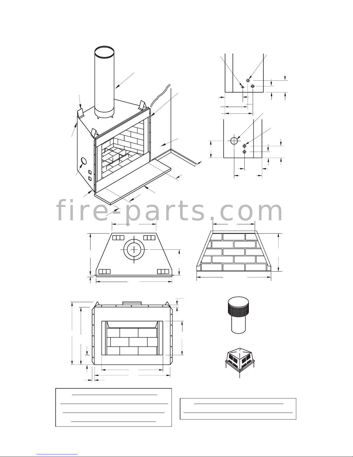
SPECIFICATIONS
0" TO
BOTTOM
OUTSIDE
AIR (LEFT
SIDE ONLY)
0.75"
AIR
SPACE
BACK
AND
SIDES
HEARTH
EXTENSION
52" X 18"
8" EACH
SIDE
NOT LESS
THAN 12" TO
PERPENDICULAR
SIDEWALL
1" AIRSPACE
TO COMBUSTIBLE
MATERIAL
COMBUSTIBLE
WALL BOARD
0" TO
TOP
SPACERS
NO COMBUSTIBLE
MATERIAL ON FACE
GAS LINE
KNOCK
OUTS
AIR KIT
KNOCK OUT
GAS LINE
KNOCK
OUTS
ELECTRICAL
OUTLET
LEFT SIDE
RIGHT SIDE
9.125"
11.435"
14.437"
41.250"
37"
41"
35"
21"
8"
32.5"
14.25"
22"
3.5"
8.717"
1"
11.217"
3.5"
9.125"
7.092"
8.717"
12.5"
41"
1"
0.625"
29"
21"
SQUARE CHASE-TOP
TERMINATION
ROUND TOP TERMINATION
CAUTION: THE STRUCTURAL
INTEGRITY OF THE MANUFACTURED
HOME FLOOR, WALL, AND CEILING/
ROOF MUST BE MAINTAINED.
WARNING: DO NOT INSTALL IN
SLEEPING ROOM OF MOBILE HOMES.
f i r e - p a r t s . c o m
Page 5

www.Astria.US.com
126767-01A 5
FIREPLACE INSTALLATION
SELECTING LOCATION
To determine safest and most efcient location
for replace, you must take into consideration
the following guidelines:
1. Location must allow for proper clearances
(see Figures 1 and 2).
2. Consider a location where replace will
not be affected by drafts, air conditioning
ducts, windows or doors.
3. A location that avoids cutting of joists or
roof rafters will make installation easier.
4. An outside air kit is available with this
replace (see Optional Outside Air Kit on
page 7).
MINIMUM CLEARANCE TO
COMBUSTIBLES
Back and sides of replace 3/4" minimum*
Floor** 0" minimum
Perpendicular wall to opening 14" minimum
Top spacers 0" minimum
Mantel clearances see Mantels, page 6
Chimney outer pipe surface 1" minimum
* Not required at nailing anges
** See step 2 of Framing
WARNING: Do not pack required air spaces with insulation
or other materials.
Minimum/Maximum Chimney Height
Minimum height of chimney, measured from
base of replace to ue gas outlet of termination, is 14.5 feet for straight ue or a ue with
one elbow set. Maximum distance between
elbows is 6 feet. For systems with two elbow
sets, minimum height is 22 feet. Maximum
height of any system is 50 feet. This measurement includes replace, chimney sections and
height of termination assembly at level of ue
gas outlet (see Figure 19, page 12).
Minimum/Maximum Chimney Height for
Outdoor Installation
The minimum height of the chimney, measured from the base of the replace to the
ue gas outlet of the termination, is 7 1/2 feet
(minimum of 4 feet of chimney pipe sections
required for outdoor installation).
FRAMING
1. Frame opening for replace using dimensions shown in Figures 1 and 2.
21.875"
41.75"
41.75"
Figure 1 - Framing Dimensions
Figure 2 - Corner Installation
2. If replace is to be installed directly on
carpeting, tile (other than ceramic) or any
combustible material other than wood
ooring, replace must be installed upon
a metal or wood panel extending full width
and depth of replace.
3. Set replace directly in front of this opening and slide unit back until nailing anges
touch side framing.
4. Check level of replace and shim with
sheet metal if necessary.
5. Before securing fireplace to prepared
framing, ember protector must be placed
between hearth extension (not included)
and under bottom front edge of replace
to protect against glowing embers falling
through. If replace is to be installed on
a raised platform, a Z-type ember protector (not included) must be fabricated to
t your required platform height. Ember
protector should extend under replace a
minimum of 1 1/2". Ember protector should
be made of galvanized sheet metal (28
gauge minimum) to prevent corrosion.
6. Using screws or nails, secure replace to
framing through anges located on sides
of replace.
52.183"
17.253"
24.399"
73.798"
MAINTAIN
3
/4"
CLEARANCE AT
SIDES AND BACK
OF FIREPLACE
3
/4" CLEARANCE
NOT REQUIRED AT
NAILING FLANGES
f i r e - p a r t s . c o m
Page 6

www.Astria.US.com
126767-01A6
DRAIN PAN (DP36)
For outdoor installations, the replace enclosure must allow for adequate drainage and
fresh air ventilation. It is recommended that
a sealed, corrosion resistant catch pan with
provision for drainage be installed under the
replace within the replace enclosure (see
Accessories on page 21).
HEARTH EXTENSION
A hearth extension projecting a minimum of
16" in front of and a minimum of 8" beyond
each side of replace opening is required to
protect combustible oor construction in front
of replace. Fabricate a hearth extension
using a material which meets the following
specications: a layer of noncombustible,
inorganic material having a thermal conductivity of K=0.84 BTU IN/FT, HR. F (or less) at 1"
thick. For example, if material selected has
a K factor of 0.25, such as glass ber, the
following formula would apply:
0.25 x 1.0" = 0.30" thickness required
0.84
Thermal conductivity "K" of materials can be
obtained from manufacturer or supplier of
noncombustible material. If hearth extension
is to be covered, use noncombustible material such as tile, slate, brick, concrete, metal,
glass, marble, stone, etc. Provide a means
to prevent hearth extension from shifting and
seal gap between replace frame and hearth
extension with a noncombustible material
(see Figure 3).
FIREPLACE INSTALLATION
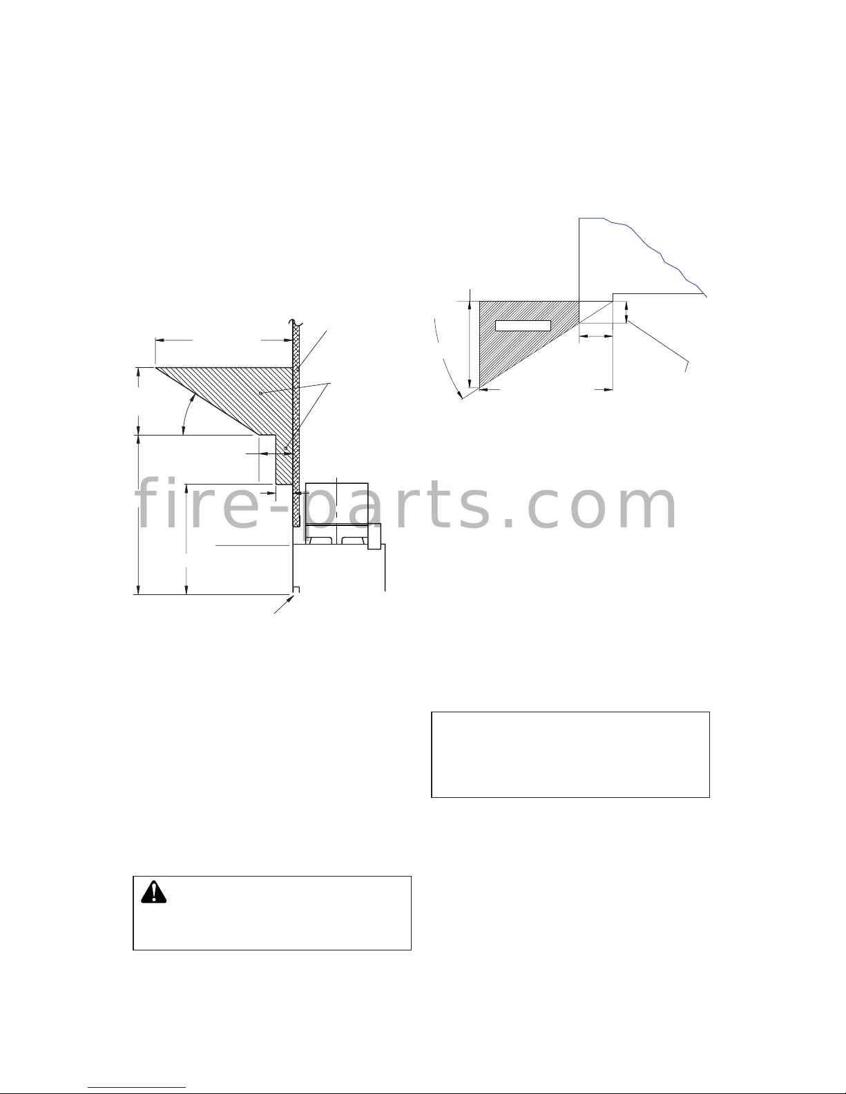
Figure 3 - Hearth Extension
Seal Gap
Fireplace Front
Ember Protector
Fireplace Front
Raised Hearth
Fireplace Front
Elevated
Ember Protector
Ember Protector
Seal Gap
Hearth
Extension
WARNING: Hearth extension
is to be installed only as shown
in Figure 3.
f i r e - p a r t s . c o m
Page 7
www.Astria.US.com
126767-01A 7
FIREPLACE INSTALLATION
Continued
12 1/4" Ref.
6"
Ref.
12" Min.
9" Min.
11/2" Max.
3" Nom.
33°
Combustible
Material
Safe
Zone for
Projection of
Combustible
Materials
Fireplace Opening
Upper
Section of
Fireplace
OPTIONAL OUTSIDE AIR KIT
(MODEL AK4/AK4F)
Installation of an outside air kit should be
performed during rough framing of replace
due to the nature of it's location. Outside combustion air is accessed through a vented crawl
space (AK4F) or through a sidewall (AK4).
See Figure 23 on page 15 for instruction of
operating air kit.
CAUTION: Combustion air
inlet ducts shall not terminate
in attic space.
VENTING INSTALLATION
MANTELS
A mantel may be installed if desired (see
Figures 4 and 5). Woodwork such as wood
trims, mantels or any other combustible
material projecting from front face, must not
be placed within 9" of replace opening and
within 6" of top louver opening. Combustible
materials above 9" and projecting more than
1 1/2" from replace must not be placed less
than 12" from top opening of replace (NFPA
STD 211, Sec. 7-3.3.3).
Figure 5 - Mantel Clearances to
Combustible Material
The maximum height for the
air vent can not exceed 3 feet
below the ue gas outlet of the
termination.
CHIMNEY PIPE
INNOVATIVE HEARTH PRODUCTS chimney
system consists of 12", 18", 24", 36" and
48" snap-lock, double-wall pipe segments,
planned for maximum adaptability to individual
site requirements. Actual lengths gained after
tting overlaps must be taken into consideration (lineal gain) and are given in lineal gain
chart (see Figure 7, page 7). Lineal gain is
actual measurable length of a part after two
or more parts are connected. For Canada, use
chimney parts designated "HT".
Figure 5 - Mantel Clearances to
Combustible Material
FIREBOX
SAFE ZONE
Top View of Fireplace
2" Max.
3.0"
Min. to
Perpendicular
Side Wall
12"
8.0"
33°
Combustible
Material Must
Not Overlap
Front Face
Mantels or any other combustible material
also may come up to the side edge of the
stainless steel face of the replace just as long
as the projection from the front face fall within
the limit shown in Figure 4 and 5.
f i r e - p a r t s . c o m
Page 8
www.Astria.US.com
126767-01A8
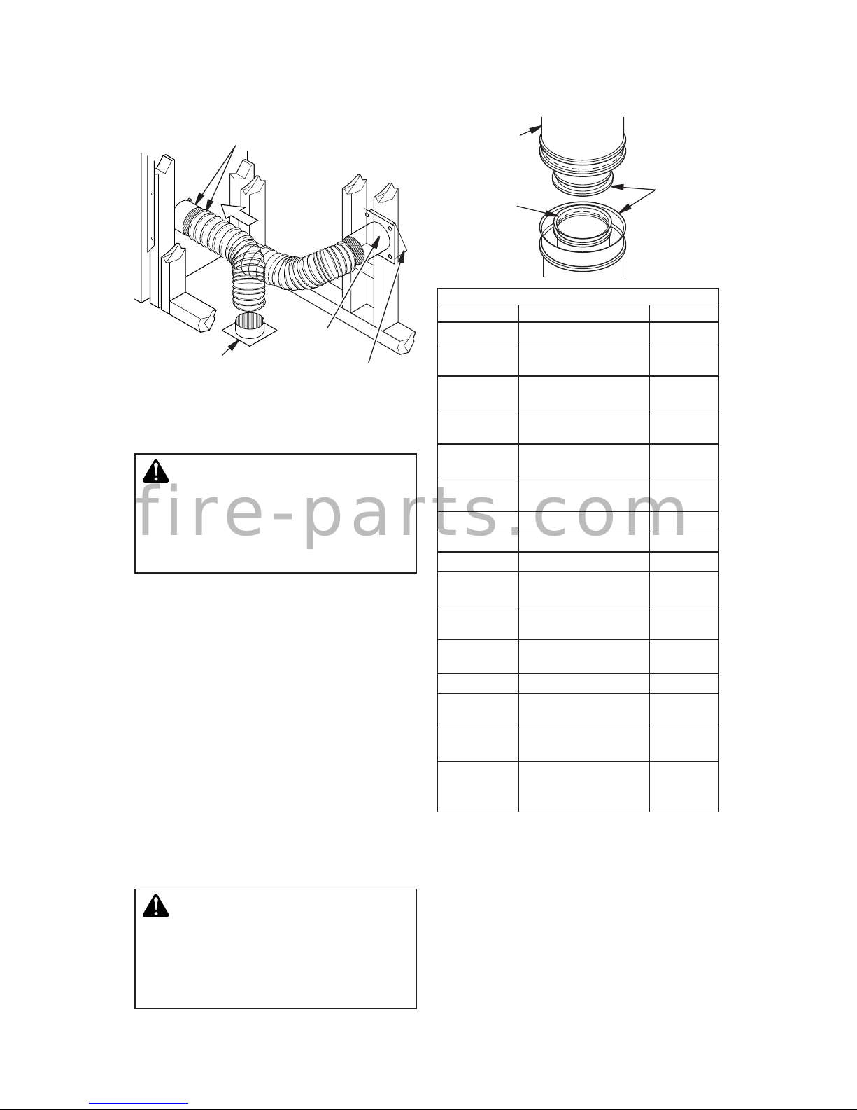
Figure 7 - Lineal Gain
Figure 6 - Outside Air Kit
Secure to Collars with Metal Tape, Screws
or Straps (Min. of 1/4" x 20" in size)
Air Inlet
Location
Must Allow
For Bushes
or Snow
Vent Hood
Required for
Wall Installation
Air Inlet
Eyebrow
Vented Crawl Space
(Check Local Codes
Before Installing in a
Vented Crawl Space)
WARNING: The opening in
collar around chimney at top of
replace must not be obstructed.
Never use blown insulation to ll
chimney enclosure.
Hemmed
End
8" Stainless
Inner Pipe
12 3/8"
Galvanized
Outer Pipe
VENTING INSTALLATION
Continued
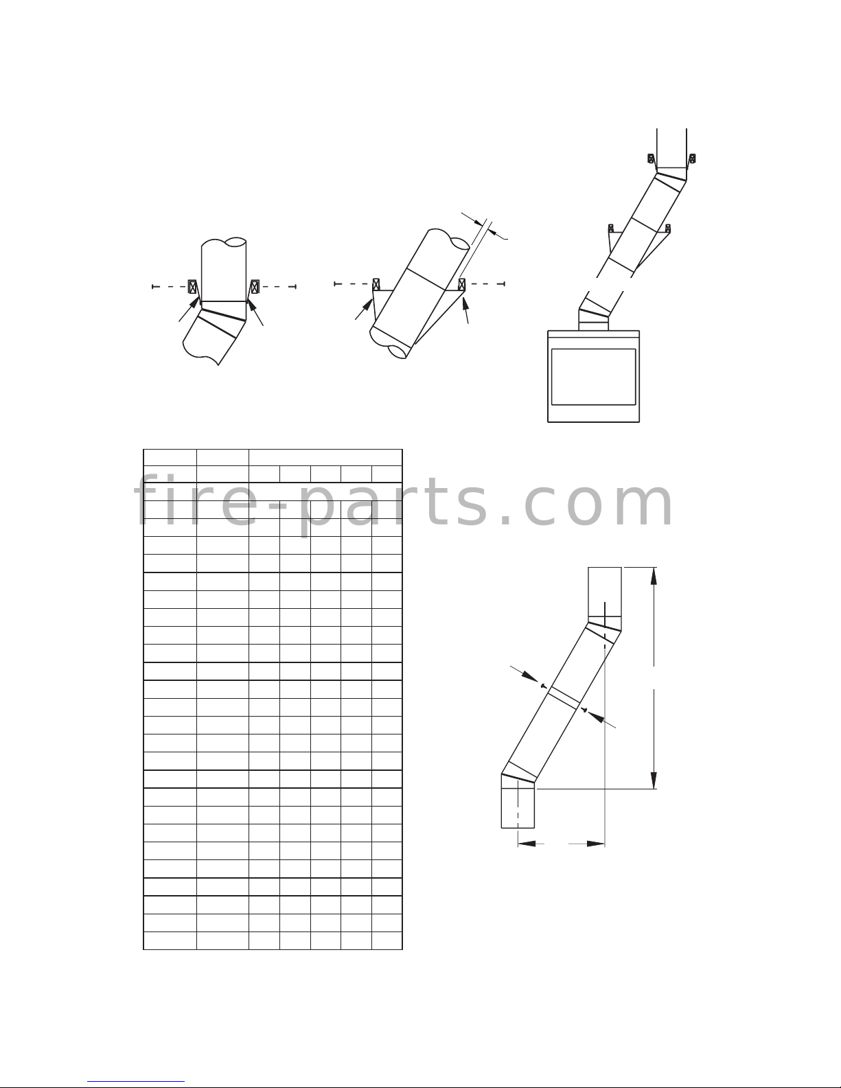
ASSEMBLY AND INSTALLATION OF
DOUBLE WALL CHIMNEY SYSTEM
Each double wall chimney section consists of
a galvanized outer pipe, a stainless steel inner ue pipe and a wire spacer. Pipe sections
must be assembled independently as chimney
is installed. When connecting chimney directly
to replace, inner ue pipe section must be
installed rst with lanced side up. Outer pipe
section can then be installed over ue pipe
section with hemmed end up. Press down
on each pipe section until lances securely
engage hem on replace starter. The wire
will assure proper spacing between inner and
outer pipe sections.
Note: For Canada, use chimney parts designated HT.
Opening in collar around
chimney at top of replace must
not be obstructed. Never use
blown insulation to ll chimney
enclosure.
LINEAL GAIN
PART NO. DESCRIPTION GAIN
36" Fireplace 37 1/2"
12-8DM
12-8HT
Pipe Section 10 5/8"
18-8DM
18-8HT
Pipe Section 16 5/8"
24-8DM
24-8HT
Pipe Section 23 5/8"
36-8DM
36-8HT
Pipe Section 34 5/8"
48-8DM
48-8HT
Pipe Section 46 5/8"
RT-8DM Round Termination 6 7/8"*
RTL-8DM Round Termination 7 3/4"*
RLT-8DM Round Termination 7 1/2"
RTT-8DM
Round Termination
with Slip Section
6 7/8" to
23 1/8"*
RTTL-8DM
Round Termination
with Slip Section
8 1/2" to
21 1/2"*
RLTT-8DM
Round Termination
with Slip Section
7 1/2" to
21 1/4"*
ET-8DM Square Chase-Top 12"*
ETO-8DM
Square Chase-Top
with Mesh
12"*
ETL-8DM
Square Chase-Top
with Slip Section
7" to 15"*
ETLO-8DM
Square Chase-Top
with Mesh & Slip
Section
12" to
25 1/2"*
* The lineal gain for the terminations is
measured to the ue gas outlet height.
f i r e - p a r t s . c o m
Page 9
www.Astria.US.com
126767-01A 9
VENTING INSTALLATION
Continued
Figure 8 - Typical Offset Installation
Return
Elbow
Offset
Elbow
Return
Elbow
Offset
Elbow
6' Max.
6' Max.
6' Max.
6' Max.
6' Max.
6' Max.
Return
Elbow
Offset
Elbow
Offset
Elbow
Return
Elbow
A
B C
Offset
Elbow
Ceiling
Support Pipe
12S-8DM
Return
Elbow
Continue to assemble chimney sections as
outlined, making sure that both inner and
outer pipe sections are locked together. When
installing double wall snap-lock chimney together, it is important to assure joint between
chimney sections is locked. Check by pulling
chimney upward after locking. Chimney will
not come apart if properly locked. It is not
necessary to add screws to keep chimney together (exception - see Figure 10, page 9).
USING ELBOW OFFSETS (30E-8DM)
1. To achieve desired offset, you may install
combinations of 12", 18", 24", 36" and 48"
length of double wall pipe (see offset chart
on page 9 and Figure 8).
Note: For systems with 2 elbow sets, mini-
mum height is 22 feet. Maximum height
for any system is 50 feet.
2. Chimney weight above offset rests on
return elbow. Straps must be securely
nailed to rafters or joists (see Figure 9,
details A and B on page 9).
3. Maximum length of pipe between supports
(return elbow or 12S-8DM) is 6' of angle
run. Maximum of two 6' angle run sections
per chimney system (see Figure 8).
4. All pipe connections between offset and
return must be secured with two screws
on outer pipe only (see Figure 10, page
9). Do not penetrate inner stainless.
f i r e - p a r t s . c o m
Page 10
www.Astria.US.com
126767-01A10
Figure 10 - Elbow Offset
VENTING INSTALLATION
Continued
Figure 9 - Ceiling Support Pipe 12S-8DM
See Detail A
OFFSET RISE CHIMNEY LENGTH
A B 48" 36" 24" 18" 12"
4 3/8" 16 3/8" ELBOW SET ONLY
9 3/4" 25 1/2" 1
12 3/4" 30 3/4" 1
15" 34 3/4" 1
18" 40" 1 1
21 1/4" 46 1/4" 1
23 3/4" 49 1/4" 1 1
27 3/4" 56 3/4" 1
30" 60 3/4" 1 1
33" 66" 1 1
36" 71" 1 1
38 1/4" 75" 2
41 1/4" 80 1/4" 1 1 1
45" 86 3/4" 2
46 3/4" 89 1/2" 1 1 1
51" 97" 1 1
53 1/4" 101" 2 1
56 1/4" 106 1/4" 2
59 1/4" 111 1/2" 1 1 1
61 3/4" 115 1/2" 2 1
64 3/4" 120 3/4" 2 1
68 1/4" 127" 1 2
70" 130" 2 1 1
74 1/4" 137 1/2" 1 2 1
76 3/4" 141 1/2" 1 2 1
79 3/4" 146 3/4" 4
OFFSET CHART (22-50 FT. SYSTEM HEIGHT)
B
A
Screws
2" Min.
Straps
Straps
Straps
Straps
Detail A
Return Elbow
Detail B
Angle
Firestop
See Detail B
Ceiling Support
Pipe 12S-8DM
f i r e - p a r t s . c o m
Page 11
www.Astria.US.com
126767-01A 11
VENTING INSTALLATION
Continued
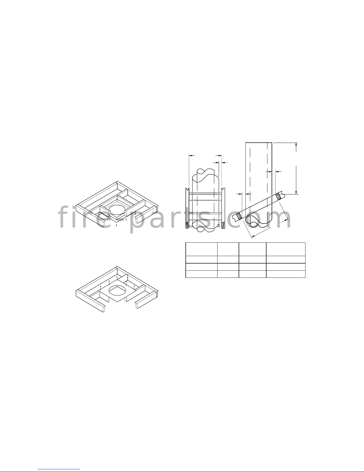
Pitch Slope Opening
"A" Max.
Used Flashing
Model No.
Flat 0° 15" V6F-8DM
0-6/12 26.6° 16 1/8" V6F-8DM
6/12- 12/12 45.0° 20 3/8" V12F-8DM
4. Remove shingles around opening measured. Cut out this section.
5. Add next sections of pipe until end
penetrates roof line. Check to see that
proper clearances are maintained. Extend
chimney by adding sections of double wall
pipe until pipe is minimum of 30" above
highest point of roof cutout. Termination
and chimney must extend a minimum of
36" above highest point where it passes
through roof.
Figure 13 - Roof Opening Measurements
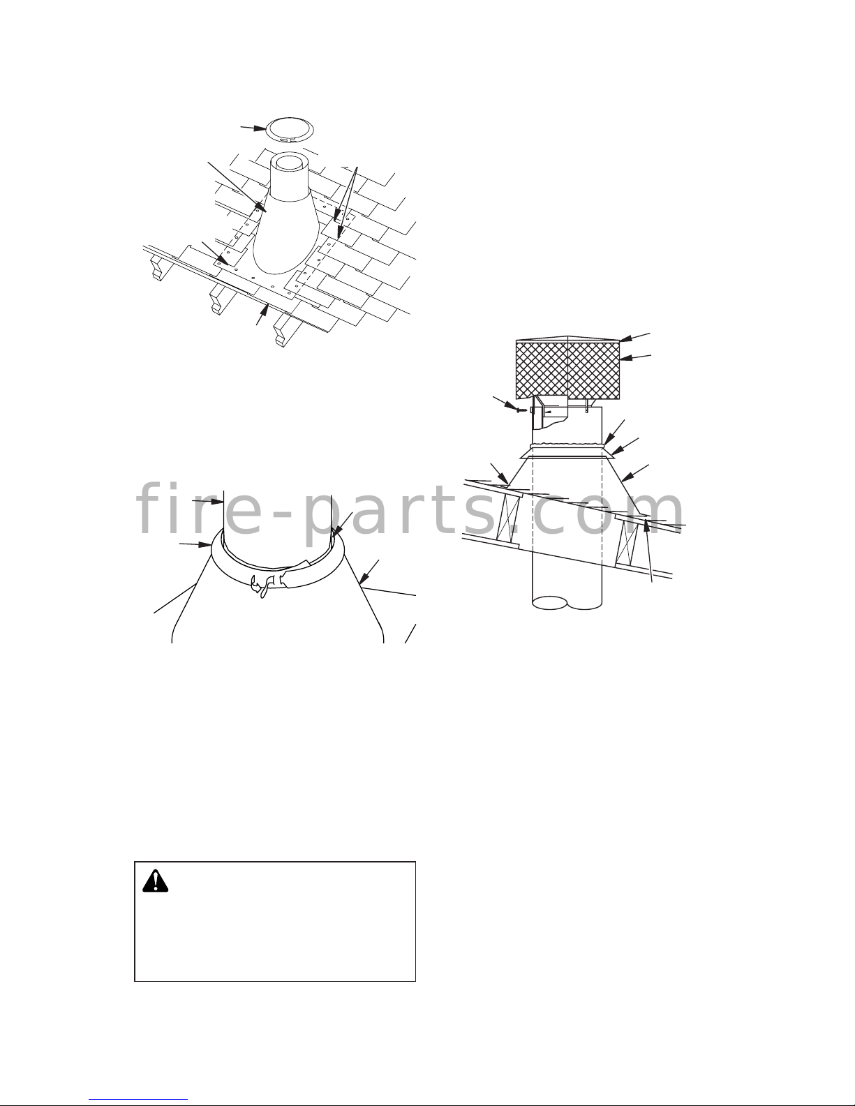
FLASHING INSTALLATION (V6F-8DM
OR V12F-8DM)
Determine ashing to be used with roof opening chart. Slide ashing over pipe until base is
at against roof. Replace as many shingles as
needed to cover exposed area and ashing
base. Secure in position by nailing through
shingles (see Figure 14, page 11). DO NOT
NAIL THROUGH FLASHING CONE.
Installing Flashing on a Metal Roof
When installing ashing on a metal roof, it
is required that putty tape be used between
ashing and roof. Flashing must be secured
to roof using #8 x 3/4" screws and then sealed
with roof coating to prevent leakage through
screw holes. A roof coating must also be applied around perimeter of ashing to provide
a proper seal.
FIRESTOP SPACERS (3600FS-8DM-1)
Firestop spacers are required at each point
where chimney penetrates a floor space.
Their purpose is to establish and maintain
required clearance between chimney and
combustible materials. When pipe passes
through a framed opening into a living space
above, restop must be placed onto ceiling
from below as shown in Figure 11.
They also provide complete separation from
one oor space to another or attic space as
required by most codes. When double wall
pipe passes through a framed opening into
an attic space, restop must be placed into
an attic oor as shown in Figure 12.
PENETRATING ROOF
To maintain a 1" clearance to pipe on a roof with
a pitch, a rectangular opening must be cut.
1. Determine center point where pipe will
penetrate roof.
2. Determine center point of roof. Pitch is
the distance the roof drops over a given
span, usually 12". A 6/12 pitch means that
the roof drops 6" for each 12" measure
horizontally down from roof rafters.
3. Use roof opening chart (Figure 13) to
determine correct opening length and
ashing required.
Figure 11 - Firestop Spacer with Living
Space Above Ceiling
Figure 12 - Firestop Spacer with Attic
Space Above Ceiling
If area above is a living space, install
restop below framed hole.
If area above is an attic or insulated area,
install restop above framed hole.
14 3/8"
(36.5 cm)
30"
(76.2 cm)
1"
(2.5
cm)
1"
(2.5
cm)
Minimum Measurements
1"
(2.5 cm)
Opening "A"
f i r e - p a r t s . c o m
Page 12
www.Astria.US.com
126767-01A12
Nail Only
Outer
Perimeter
of Flashing
Storm Collar
Flashing
Cone
Underlap Shingles
at Bottom
Overlap
Shingles Top
and Sides Only
Figure 14 - Flashing Installation
Figure 15 - Storm Collar
Chimney
Pipe
Waterproof
Caulk
Storm
Collar
Flashing
Storm Collar Installation (SC1)
Place storm collar over pipe and slide down
until it is snug against open edge of ashing (see Figure 15). Apply waterproof caulk
around perimeter of collar to provide a proper
seal.
Terminations/Spark Arrestor
Fireplace system must be terminated with
listed round top or chase terminations. In any
case, refer to installation instructions supplied
with termination. Terminations approved for
this replace are RT-8DM, RTL -8DM and
RLT-8DM that can be used for ashing or
chase and ET-8DM, ETO-8DM, ETL-8DM
and ETLO-8DM for chase style termination
only. Figure 17 shows an RTL-8DM round
top termination.
CAUTION: Do not seal openings on the rooftop ashing. Follow the installation instructions
provided with the termination
being used.
VENTING INSTALLATION
Continued
Attach Bracket
Tabs to
Outer Pipe
(3 Places)
Secure with
Screws
RTL-8DM
Level of
Flue Gas
Outlet
Caulk
Collar
Flashing
Underlap Shingles
Bottom Only
Figure 16 - Termination
Overlap
Shingles Top
and Sides
Terminations with 16" slip pipe sections are
available. RTT-8DM, RTTL-8DM and RLTT8DM are approved for ashing installations.
When needed, these adjustable terminations
may be used in combination with pipe assembly to achieve correct chimney height.
Note: In rare instance there is a problem with
side driven rain or wind or chimney is not
drafting properly, an ADS-8DM (Anti-Draft
Shield) can be used with round terminations.
CHASE INSTALLATIONS
Instructions for chase installations are included with chase style termination chosen. In a
multiple chase installation, be sure to provide
adequate distance between terminations to
prevent smoke spillage from one termination
to another. We suggest that terminations be
separated at least 24", center to center and
stacked at a vertical height difference of 18"
(see Figure 17, page 12).
Note: If a decorative shroud is to be installed,
contact manufacturer for specications.
f i r e - p a r t s . c o m
Page 13
www.Astria.US.com
126767-01A 13
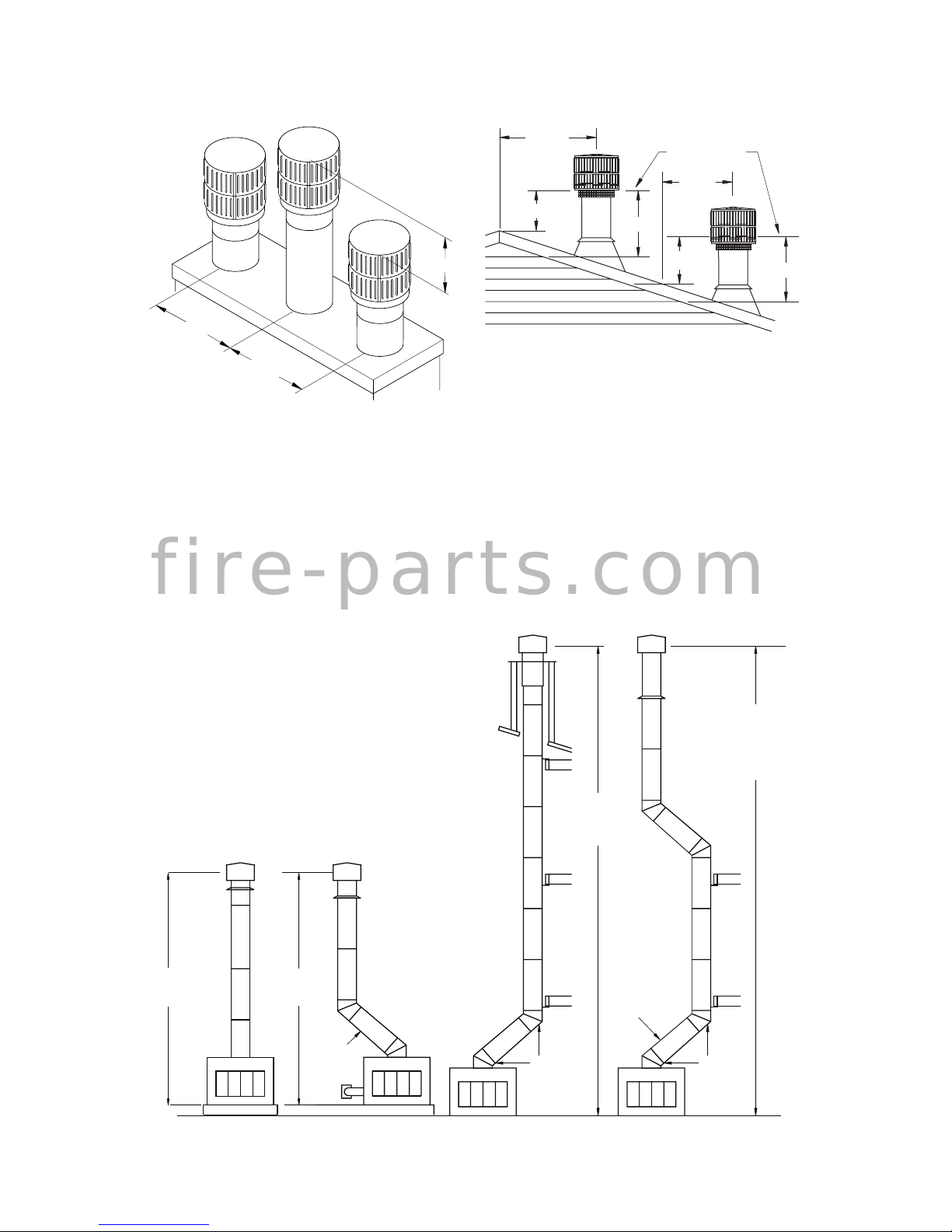
Figure 18 - 10 Foot Rule
10 FOOT RULE
All ue gas outlet chimney terminations must
extend a minimum of 3 feet in height above
highest point where it passes through roof and
must be at least 2 feet above highest point of
the roof that is within a horizontal distance of
10 feet (see Figure 18).
VENTING INSTALLATION
Continued
FINISHING THE FIREPLACE
Combustible materials, such as wallboard,
gypsum board, sheet rock, drywall, plywood,
etc. may make direct contact with sides and
top around the replace face. It is important
that combustible materials do not overlap face
itself. Brick, glass, tile or other noncombustible
materials may overlap front face provided
they do not obstruct essential openings such
as louvered slots. When overlapping with
a noncombustible facing material, use only
noncombustible mortar or adhesive.
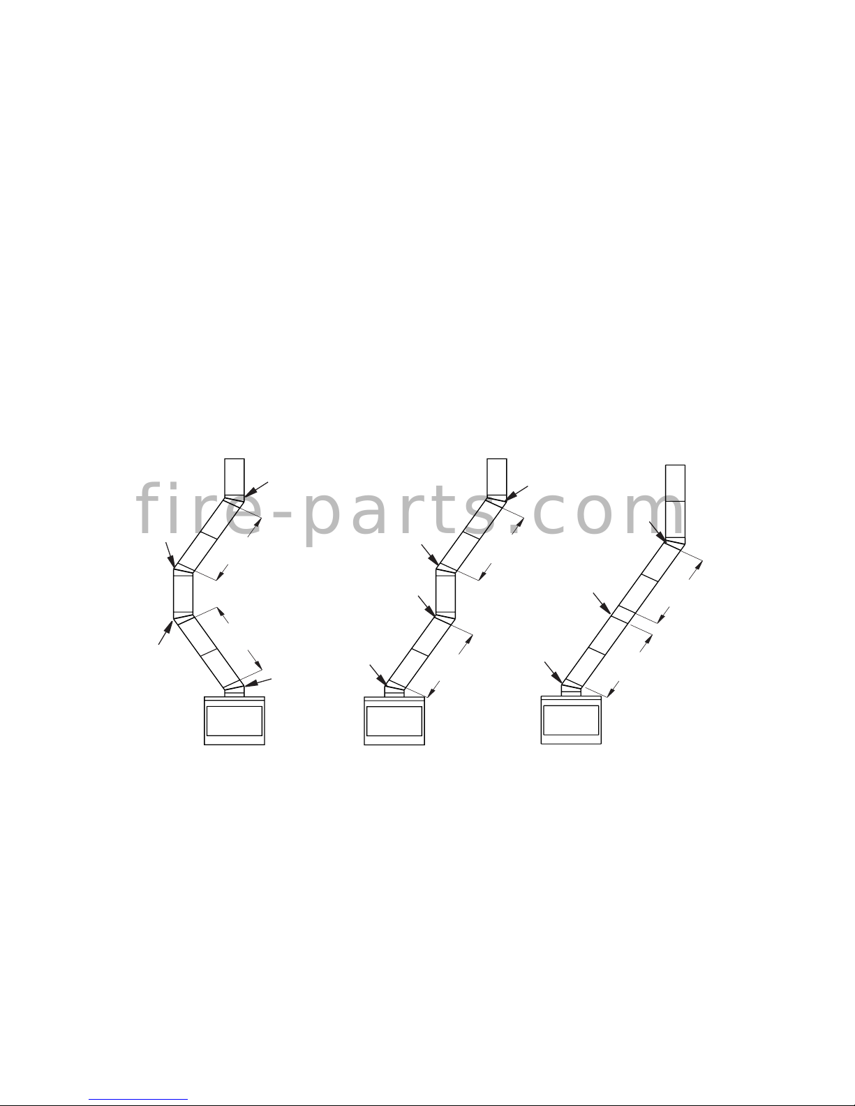
30E-8DM
EFFECTIVE HEIGHT
OF TERMINATION CAP
EFFECTIVE HEIGHT
OF TERMINATION CAP
EFFECTIVE HEIGHT
OF TERMINATION CAP
EFFECTIVE HEIGHT
OF TERMINATION CAP
MINIMUM
HEIGHT
14.5 FT.
MINIMUM
UP TO
6FT. MAX.
UP TO
6FT. MAX.
HEIGHT
14.5 FT.
MIN. HEIGHT
OF 22 FT. (WITH
2 ELBOW SETS)
MAX. HEIGHT
OF
50 FT.
MAX. HEIGHT
50 FT.
(ANY SYSTEM)
30E-8DM
Figure 19 - Typical Residential Installations
Figure 17 - Multiple Chase Installation
24" Min.
24" Min.
18"
Min.
Typ.
10'
2' Min.
10'
3' Min.
2' Min.
3' Min.
Level of
Flue Gas
Outlet
f i r e - p a r t s . c o m
Page 14

www.Astria.US.com
126767-01A14
OPTIONAL GAS LINE INSTALLATION
Figure 21 - Gas Line Knockout
Side
Firebrick
Finished
Side
Refractory
Knockout
Plug
Outside of
Fireplace
Gas Line
Conduit
Insulation
Gas
Conduit
Cover
1/2" Dowel
Gas line hook up should be done by your
supplier or a qualied service person.
Note: Before you proceed, make sure your
gas supply is turned off.
Use only a 1/2" black iron pipe and appropriate ttings.
1. Remove knockout indentation on refractory or rebrick wall located above refractory
hearth oor. Knockout indentation must
be rmly tapped with any solid object,
such as a 1/2" dowel, until it is released.
Remove fragmented portions of refractory
(see Figure 21).
Seal
Opening
with
Refractory
Cement
Outside of
Fireplace
Gas
Line
Conduit
Repack
Insulation
Incoming
1/2" Black
Iron Pipe
Side
Firebrick
Finished
Side
Provide Enough Threaded
End for Fitting Connection
Figure 22 - Gas Line Installation
2. Remove gas line cover plate located on
either side of replace and pull out insulation from gas line conduit sleeve. Save
insulation for reuse.
Note: Secure incoming gas line to wood
framing to provide rigidity for threaded end.
4. Repack insulation around gas line and into
sleeve opening. Seal any gaps between
gas line and refractory knockout hole with
refractory cement or commercial furnace
cement. Install gas appliance or cap off
gas line if desired.
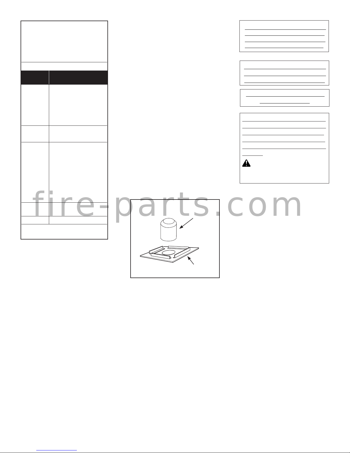
PUREFIRE HOOD INSTALLATION
1. The PureFire hood supplied with this replace is packaged in a separate box and
placed in the rebox during shipping.
2. Remove hood from box.
3. Lift the hood up into the replace at an
angle with the rear facing up. Set the
front section of the hood on the refractory
brackets. Then tilt the rear toward the back
of the replace so the hood is resting on
refractory brackets (see Figure 20). The
rear of the hood will be touching the rear
of the replace.
Figure 20 - Installing PureFire Hood
Hood
Refractory
Retainer
3. Run a 1/2" black iron gas line into replace
through rear at gas line conduit sleeve (if
using a raised platform, add height). Provide
sufcient gas line into replace chamber for
tting connection (see Figure 22).
f i r e - p a r t s . c o m
Page 15

www.Astria.US.com
126767-01A 15
OPTIONAL GAS LINE INSTALLATION
Continued
OPERATION AND MAINTENANCE
GLASS DOORS
Glass doors are optional with this replace.
When replace is in operation, doors must
be fully opened or fully closed position only
or a re hazard may be created (see Figure
23, page 15).
A replace equipped with glass doors operates much differently than a replace with an
open front. A replace with glass doors has a
limited amount of air for combustion. Excessive heat within replace can result if too large
a re is built or if combustion air gate is not
completely open.
If you install a decorative gas appliance
(vented gas log), decorative gas appliance
must comply with the Standard for Decorative
Gas Appliance for Installation in Solid Fuel
Burning Fireplaces, ANS Z21.60 or Z21.84
and shall also be installed in accordance with
the National Fuel Gas Code, ANSI 7223NFPA
54 latest edition.
WARNING: To avoid the risk
of damaging the replace materials and increasing the risk of
spreading a re, do not use the
replace to cook or warm food.
WARNING: If the replace
has been used for wood burning, rebox and chimney must
be cleaned of soot, creosote and
ashes be a qualied chimney
cleaner. Creosote will ignite if
heavily heated.
WARNING: When using a dec-
orative vented gas log, damper
must be removed or permanently
locked in fully open position and
glass doors must be in fully open
position.
The following tips should be used to assure
that both fireplace and glass door retain
their beauty and function properly. Both
ue damper and glass doors must be fully
opened before starting a re. This will provide
sufcient combustion air and maintain safe
temperatures in rebox.
IMPORTANT: Glass must be allowed to
warm slowly and evenly. Tempered glass
will withstand a gradual temperature rise to
550° F, which is more than a normal re will
generate. Such materials as pitch/wax laden
logs, very dry mill end lumber and large
amounts of paper or cardboard boxes can
create an excessively hot re and should not
be burned in this replace. Always keep re
back from doors and never allow ames to
contact glass.
CAUTION: All gas piping and
connections must be tested for
leaks after installation is com-
pleted. After ensuring that gas
valve is on, apply soap and water
solution to all connections and
joints. Bubbles forming show a
leak. Correct all leaks at once.
DO NOT USE AN OPEN FLAME
FOR LEAK TESTING AND DO
NOT OPERATE ANY APPLIANCE
IF A LEAK IS DETECTED. LEAK
TESTING SHOULD BE DONE
BY A QUALIFIED SERVICE
PERSON.
Note: A INNOVATIVE HEARTH PRODUCTS
hood must be installed when using an unvented gas log set (see Accessories on page 21).
WARNING: Do not operate
an unvented gas log set in this
replace with chimney removed.
f i r e - p a r t s . c o m
Page 16

www.Astria.US.com
126767-01A16
Figure 24 - Damper and Air Kit Handle
OPERATION AND MAINTENANCE
Continued
OUTSIDE AIR AND DAMPER
HANDLE OPERATION
Damper handle, which opens and closes
damper blade, is located in upper front face
of replace. Pushing handle into left of keyway slot will free damper blade to automatically open. Pushing handle into right will lock
damper blade closed (see Figure 24).
Outside air kit handle is located at left hand
side of fireplace (see Figure 24). Pulling
handle out will free outside air door to open.
Pushing handle in will lock door closed.
WARNING: Risk of re! Replace grate with INNOVATIVE
HEARTH PRODUCTS model
125186-02 only. This grate has
been designed to keep the operation of your replace safe
and efcient.
For further operating guidelines, instructions and warranty information, please refer to your homeowner's guide or contact
your authorized dealer.
Cleaning Glass
Clean glass with any commercial glass
cleaner or soap and water. Do not use any
abrasive material to clean glass. Do not clean
glass with any cool water if glass is still hot
from re and smoke.
A gas line or gas log lighter may be installed
for the purpose of installing a vented or ventfree decorative gas appliance incorporating an
automatic shutoff device and complying with
the Standard for Decorative Gas Appliances
for Installation in Vented Fireplaces, ANSI
Z21.60 or American Gas Association draft
requirements for Gas Fired Log Lighters for
Wood Burning Fireplaces, Draft NO. 4 dated
August, 1993.
If you wish to install an unvented (vent-free)
gas log set, only unvented gas log sets which
have been found to comply with the standard
for unvented room heaters, ANSI Z21.11.2 are
to be installed in this replace.
Figure 23 - Glass Doors
Doors Fully Closed
Doors Fully Opened
Fireplace Front
Fireplace Front
WARNING: Fireplaces
equipped with glass doors
should be operated only with
doors fully opened or doors fully
closed. Doors, if left partly open,
may draw gas and ame out of
the replace opening creating
risks of both re and smoke.
OPEN
CLOSE
Damper
Handle
Outside Air
Kit Handle
Keyway
Slot
Handle
Retainer
f i r e - p a r t s . c o m
Page 17

www.Astria.US.com
126767-01A 17
MANUFACTURER: FMI Products, LLC
MODEL NO: SCAT36 36" Woodburning Fireplace
PARTICLE EMISSIONS: 4.8 GRAMS/KG OF WOOD BURNED
FIREPLACE
SMOKE EMISSIONS RANGE
Higher Emissions
Lower Emissions
0
12.0
THIS MODEL
EPA PHASE 2 EMISSIONS LEVEL
4.8
5.1
Better
Worse
U.S. Environmental Protection Agency
Wood-burning Fireplace Program
Phase 2 Qualified models are cleaner and pollute less than those models that
have not met this emissions level. Exposure to smoke has been associated with
respiratory illness and other health problems. Models that have lower smoke
emissions may reduce your risk.
PHASE 2 QUALIFIED
For more information go to www.epa.gov/burnwise
Fireplaces with lower emissions produce less smoke when installed and operated properly.
* EPA has determined, based on testing by an accredited independent laboratory and a certification
of conformity by a nationally recognized certification body, that this model qualifies at the Phase 2
emissions level for U.S. EPA's Voluntary Fireplace Program.
VSCAT36 36" Woodburning Fireplace
For proper operation, catalyst must be replaced every 3 to 5 years.
125574-04
PUREFIRE EMISSION CONTROL SYSTEM
This replace is equipped with a PureFire
Emission Control System. The Catalytic
Hood system reduces particulates emissions
in a wood burning replace to meet the EPA
Wood-Burning Fireplace Program Phase 2
emission level.
The EPA qualifying label, shown below, will be
afxed to the catalyst. Before lighting the rst
re, remove and maintain this label in a safe
place if needed for permits or building inspection. Prior to beginning installation, contact
your local building ofcial to determine the
need to obtain a permit. For proper operation,
catalyst must be replace every 3 to 5 years.
FUELING GUIDELINES
The replace grate must always be secured to
the retaining brackets provided. The position
of the grate must be centered against the back
wall of the rebox.
Burn only dry, seasoned (cured) wood with
less than 20% moisture. Avoid the use of
treated, painted and laminated wood. Never
burn garbage or other foreign materials. Do
not use articial logs, colored newspaper or
petroleum based re starters. Avoid wood with
high salt content. All of these materials may
contain compounds which can shorten the
life of the catalyst. Wet or unseasoned wood
may lower catalytic temperatures and result
in inefcient operation.
The catalyst is designed to function at optimum efciency when the replace is burning
clean, dry, cord wood as replace fuel. A
simple visual inspection of the chimney during the wood burning process will determine
catalyst performance.
The fuel load should always be placed on
the back of the grate. Use clean dry wood,
seasoned cord wood is the best choice.
Never burn trash, plastics, gasoline, rubber,
industrial solvents, ammable liquids, naptha,
household garbage, material treated with
petroleum products, leaves, paper products,
cardboard or salt driftwood.
Refer to your INNOVATIVE HEARTH PRODUCTS Homeowner's Guide included with your
replace for proper re building technique and
ash removal procedures. These fueling guidelines must be followed in order to achieve
maximum emissions performance from the
PureFire System.
OPERATION
The proper use of a wood burning replace
equipped with the catalyst will signicantly
reduce the emissions that it produces. Simple
fuel considerations with regard to moisture
content, size, and quality of fuel will help
control the production of wood smoke and
improve the performance of the catalyst and
replace efciency. With proper care, the
catalyst will provide years of fuel savings
and lowered emissions. By following some
simple guidelines, you will ensure maximum
performance and longevity.
f i r e - p a r t s . c o m
Page 18

www.Astria.US.com
126767-01A18
PUREFIRE EMISSION CONTROL SYSTEM
Continued
The smoke that is usually seen coming out
of a chimney is essentially a combination of
unburned fuel (carbon and hydrogen) and
moisture in the form of water vapor. The catalyst is a technology that provides secondary
combustion for the wood burning process.
MAINTENANCE
The PureFire System is a maintenance free
technology. Do not attempt to remove or clean
the combustor. The direct ame from the re
will clean the combustor. Only a certified
technician should remove the unit. To ensure
proper replace operation, the PureFire System should be replaced every 3 to 5 years
(see Parts on page 19).
NOTE: Chimney smoke may be visible during
the rst 8 to 10 minutes of replace operation
when the re is rst getting started and the
nal 8 to 10 minutes of operation while the re
is dissipating. Under normal operating conditions, you should see little or no smoke coming
out of the chimney. If continuous smoke is
visible, make sure only dry seasoned wood
is being burned. If visible smoke continues,
the combustor has ceased to function or
there is thermal crumbling. Call INNOVATIVE
HEARTH PRODUCTS at 1-800-655-2008 for
replacement parts.
WARRANTY
INNOVATIVE HEARTH PRODUCTS at
1-800-655-2008 warranty obligations for
the PureFire Emissions Control System are
limited to the terms set forth below.
INNOVATIVE HEARTH PRODUCTS at
1-800-655-2008 warrants to the consumer
who purchases a new solid fuel burning replace containing a PureFire Emissions Control
System as a new component, to replace the
catalyst at no charge should it cease to function within three years from the date of purchase. The PureFire Catalytic Component is
designed to perform efciently for three years
of replace operation. ONLY recommended
fuels should be burned. Follow the fueling
directions in manufacturers operation manual.
For warranty purposes, proof of replace purchases is required. Labor for removal and/or
installation of the catalytic component is not
the responsibility of the manufacturer.
Neither INNOVATIVE HEARTH PRODUCTS at 1-800-655-2008 nor the dealer
who sells the PureFire Emissions Control
System is responsible for indirect, incidental,
special, punitive or consequential damages
arising out of the improper use of this product
or the continued use of this product beyond
the required replacement period.
f i r e - p a r t s . c o m
Page 19
www.Astria.US.com
126767-01A 19
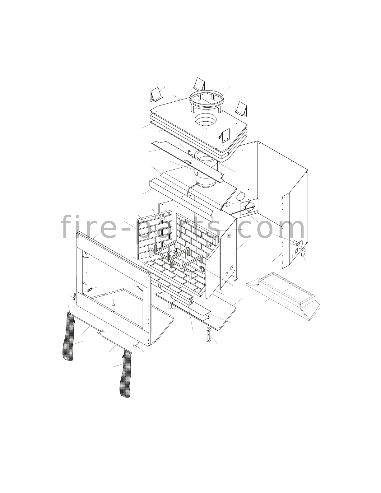
PARTS
WOOD BURNING FIREPLACE MODELS CAT36P2 AND CAT36P3
9
26
16
27
16
27
4
32
34
19
12
25
20
30
17
8
1
5
21
2
35
18
11
14
3
13
22
10
6
31
7
37/38
36
28
29
24
23
15
33
f i r e - p a r t s . c o m
Page 20
www.Astria.US.com
126767-01A20
PARTS
WOOD BURNING FIREPLACE MODELS CAT36P2 AND CAT36P3
This list contains replaceable parts used in your replace. When ordering parts, see Replacement Parts on page 21 of this manual.
KEY
NO. PART NO. DESCRIPTION QTY.
1 ** Insulation Pan 1
2 ** Fireplace Top 1
3 ** Fireplace Surround 1
4 106642-01 Air Rod Retainer 1
5 106643-01 Damper Rod Retainer 1
6 ** Firebox Bottom 1
7 ** Firebox Surround 1
8 ** Air Separator 1
9
See Page 20
Left Refractory 1
10
See Page 20
Right Refractory 1
11
See Page 20
Rear Refractory 1
12
See Page 20
Bottom Rear Refractory 1
13
See Page 20
Bottom Front Refractory 1
14 ** Firebox Support Leg 2
15 ** Damper Can Collar 1
16 106691-01 Screen Rod 2
17 ** Firebox Top Assembly 1
18 ** Air Kit Door Assembly 1
19 ** Face Weldment 1
20 125562-02 Air Deector 1
21 ** Fireplace Top Insulation 1
22 107775-01 Access Panel 1
23 107854-01 Right Refractory Bracket 1
24 107854-02 Left Refractory Bracket 1
25 125186-02 Grate 1
26 11418 Push-On Nut 2
27 110890-01 Stainless Screen 2
28 ** Collar Insulation 1
29 20023 Chimney Starter Collar 1
30 20027 Refractory Retainer 2
31 117895-01 Grate Retainer 2
32 111073-01 Door Stop 1
33 125208-01 PureFire Catalytic Hood 1
34 20090 Spring Clip 2
35 20280 Top Spacer 4
36 21171 Conduit Plate Cover 4
37 21379 Gas Conduit 2
38 21380 Gas Conduit 2
PARTS AVAILABLE NOT SHOWN
20093 Ember Protector 2
124996-01 Hood Retaining Bracket Right 1
124996-02 Hood Retaining Bracket Left 1
** Not a eld replaceable part.
f i r e - p a r t s . c o m
Page 21
www.Astria.US.com
126767-01A 21
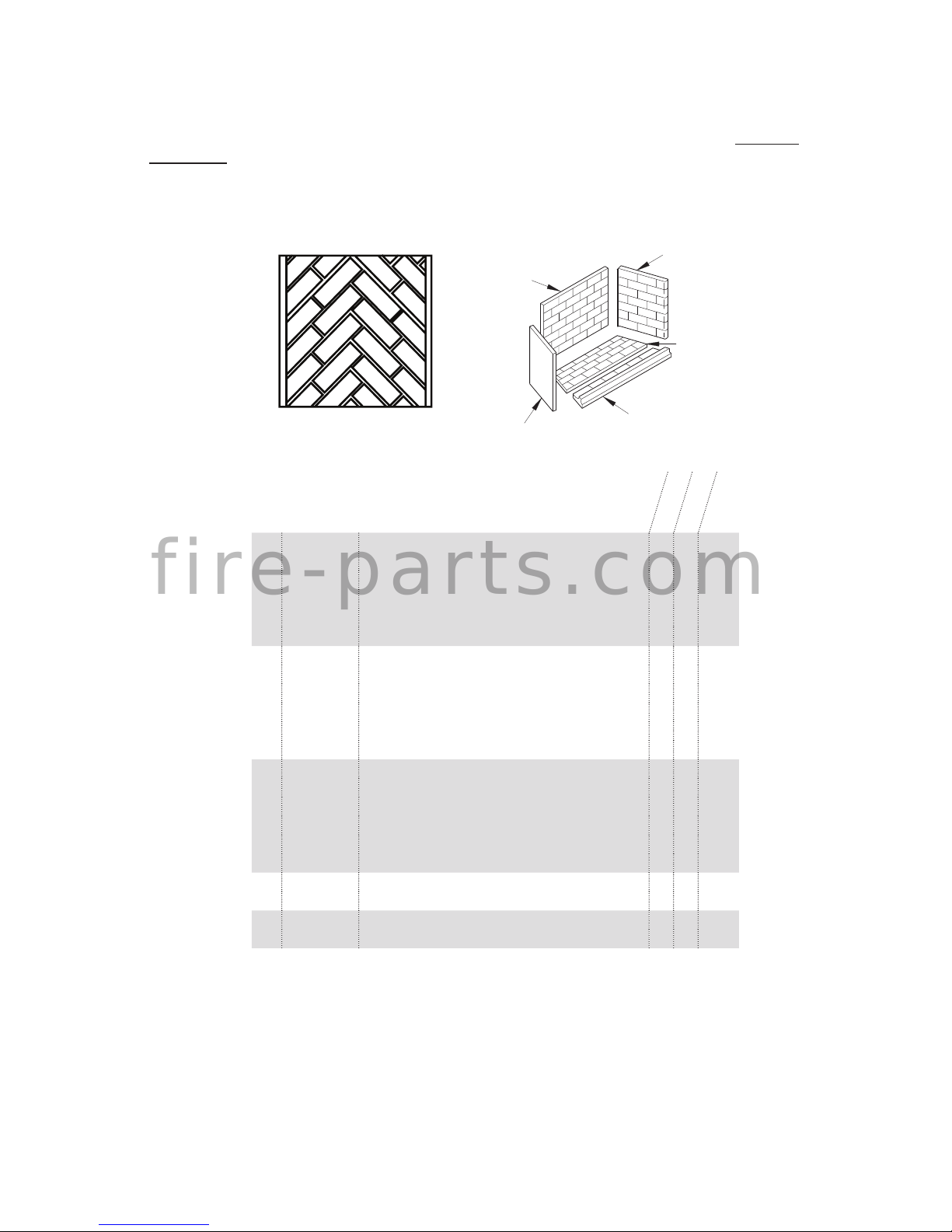
Rear
Left Side
Front Bottom
Bottom
Right Side
KEY
NO. PART NO. DESCRIPTION QTY.
9 106658-03 Left Refractory, Textured White Brick • 1
108164-03 Left Refractory, Textured White Herringbone • 1
106658-02 Left Refractory, Textured Red Brick 1
108164-02 Left Refractory, Textured Red Herringbone 1
106658-01 Left Refractory, Smooth White Brick 1
108164-01 Left Refractory, Smooth White Herringbone 1
10 106659-03 Right Refractory, Textured White Brick • 1
108165-03 Right Refractory, Textured White Herringbone • 1
106659-02 Right Refractory, Textured Red Brick 1
108165-02 Right Refractory, Textured Red Herringbone 1
106659-01 Right Refractory, Smooth White Brick 1
108165-01 Right Refractory, Smooth White Herringbone 1
11 106660-03 Rear Refractory, Textured White Brick • 1
108166-03 Rear Refractory, Textured White Herringbone • 1
106660-02 Rear Refractory, Textured Red Brick 1
108166-02 Rear Refractory, Textured Red Herringbone 1
106660-01 Rear Refractory, Smooth White Brick 1
108166-01 Rear Refractory, Smooth White Herringbone 1
12 110899-01 Bottom Rear Refractory, White Brick • • 1
110899-02 Bottom Rear Refractory, Red Brick 1
13 110900-01 Bottom Front Refractory, White Brick • • 1
110900-02 Bottom Front Refractory, Red Brick 1
CAT36P2
CAT36P3
REFRACTORY BRICK
PARTS
WOOD BURNING FIREPLACE MODELS CAT36P2 AND CAT36P3
This list contains replaceable parts used in your replace. When ordering parts, see Replacement Parts on page 21 of this manual.
f i r e - p a r t s . c o m
Page 22
www.Astria.US.com
126767-01A22
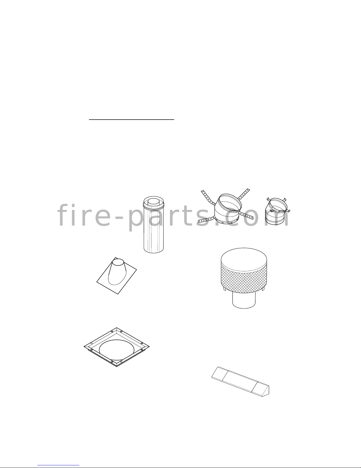
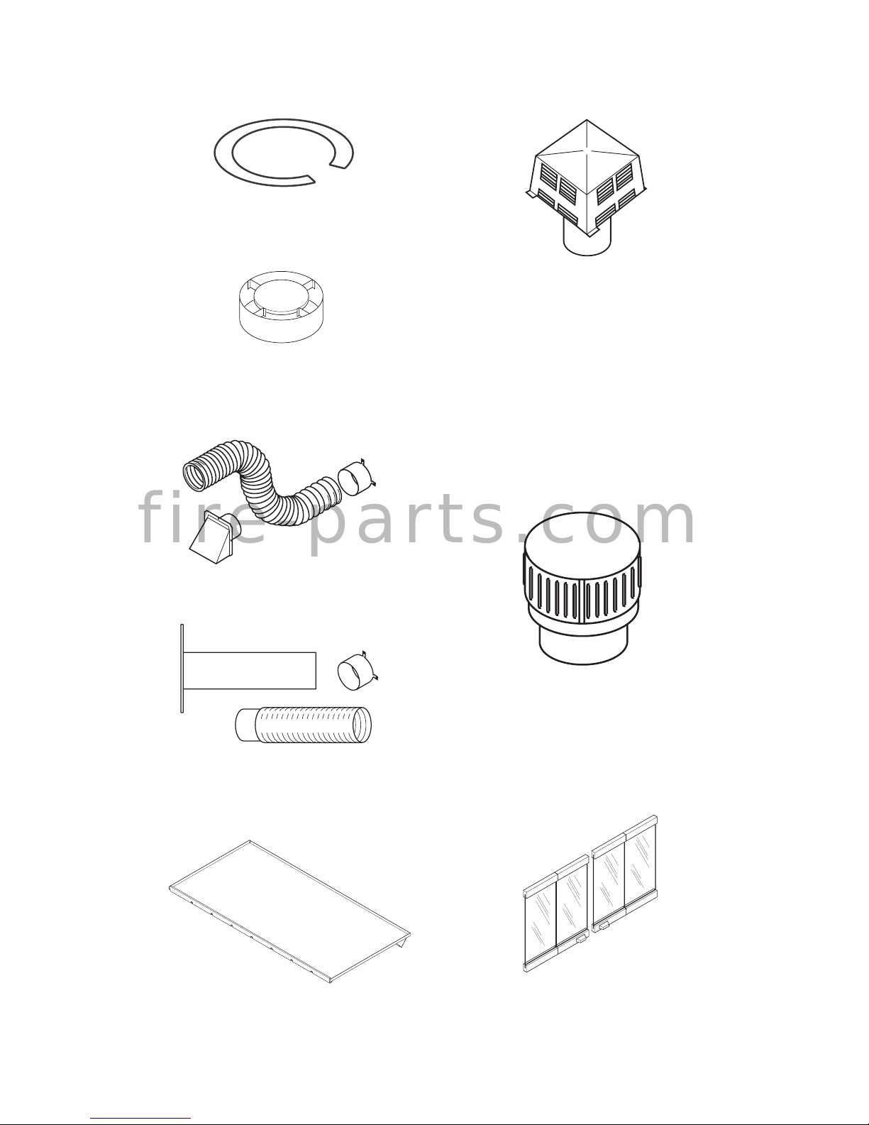
ACCESSORIES
DOUBLE WALL PIPE
12-8DM 12-8HT
18-8DM 18-8-HT
24-8DM 24-8HT
36-8DM 36-8HT
48-8DM 48-8HT
ROOF FLASHING
0 TO 6/12 PITCH - V6F-8DM
6/12 TO 12/12 PITCH - V12F-8DM
30° OFFSET AND RETURN
30E-8DM
FIRESTOP SPACER
3600FS-8DM-1
TECHNICAL SERVICE
You may have further questions about installation, operation, or troubleshooting. If so,
contact INNOVATIVE HEARTH PRODUCTS
at 1-800-655-2008. When calling please
have your model and serial numbers of your
heater ready.
You can also visit our web site at
www.Astria.US.com.
REPLACEMENT PARTS
If this product is missing a part or has a broken
component, please do not return it to the store.
Call INNOVATIVE HEARTH PRODUCTS at
1-800-655-2008 to answer questions and
replace parts under warranty.
Note: Use only original replacement parts.
This will protect your warranty coverage for
parts replaced under warranty.
When calling or writing, please have your
model and serial numbers of your replace
ready.
Model and serial number information are in the
replace's rating plate located in the screen
pocket to the left or right of the face opening.
MESH ROUND TOP TERMINATIONS
RT-8DM, RT-8HT, RTL-8DM AND RTL-8HT
MESH ROUND TOP TERMINATIONS
WITH SLIP SECTION
RTT-8DM, RTT-8HT, RTTL-8DM AND
RTTL-8HT
ADJUSTABLE HOOD
HS36
Required when installing a vent-free gas log
in this replace.
f i r e - p a r t s . c o m
Page 23
www.Astria.US.com
126767-01A 23
BI-FOLD GLASS DOOR
BDO36 - Black
BDO36B - Brushed Brass
BDO36P - Platinum
OUTSIDE AIR KIT FOR SIDE WALL
INSTALLATION - AK4
OUTSIDE AIR KIT FOR FLOOR
INSTALLATION
AK4F
ACCESSORIES
Continued
DRAIN PAN DP36
ANTI-DRAFT SHIELD
(Round Top Termination Only)
ADS-8DM
STORM COLLAR
SC1-1
ROUND TOP TERMINATIONS WITH
LOUVERS
RLT-8DM, RLT-8HT
ROUND TOP TERMINATIONS WITH
LOUVERS WITH SLIP SECTION
RLTT-8DM, RLTT-8HT
SQUARE TOP TERMINATION WITH
LOUVERS
ET-8DM, ET-8HT
SQUARE TOP TERMINATION WITH
LOUVERS AND SLIP SECTION
ETL-8DM, ETL-8HT
MESH SQUARE TOP TERMINATION
ETO-8DM
MESH SQUARE TOP TERMINATION
WITH SLIP SECTION
ETLO-8DM
f i r e - p a r t s . c o m
Page 24
Canadian code CAN/ULC-S610-M87 and
other pertinent codes require stainless steel
chimney for the installation of this fireplace.
A Cold Air Climate Kit is also required in
Canada and is recommended for cooler
regions in the United Stated. Below, find a
list of approved stainless steel parts.
Chimney Parts List for Canada
Model No.
12-8HT 12" Section Double Wall Pipe
18-8HT 18" Section Double Wall Pipe
24-8HT 24" Section Double Wall Pipe
36-8HT 36" Section Double Wall Pipe
48-8HT 48" Section Double Wall Pipe
30E-8HT 30" Offset and Return
12S-8HT Chimney Support
RT-8HT Round Top w/ Mesh Screen
RTT-8HT* Round Top w/ Slip Section
RLT-8HT Round Top w/ Louvers
RLTT-8HT* Round Top w/ Slip Section
ET-8HT* Square Top
ETL-8HT* Square Top w/ Slip Section
AP-8HT Anchor Plate/Collar Assembly
f i r e - p a r t s . c o m
CAK-8 Cold Air Collar Kit
*When ordered alone, this part cannot ship
via parcel delivery services.
8" Hi-Temp
Woodburning Chimney
& Mesh
& Louvers
(Masonry Fireplaces)
A manufactured shroud which
has been approved by a national
testing agency for use with this
fireplace may be used if installed
in accordance with the instructions by its manufacturer. A
locally fabricated shroud may be
used with IHP Shroud Leg Spacer
Kit (SLK) in accordance with
instructions provided with the
shroud.
When penetrating a ceiling
into an attic, a firestop thimble
(38FST or FST30) is required
to avoid intrusion by insulation
and recommended to negotiate a
joist.
IMPORTANT NOTICE
IMPORTANT NOTICE
Thimble 38FST
or FST 30
NOTICE: The firebox canopy (hood)
must not be modified or replaced with
a canopy that may be provided with
the unvented decorative room heater.
CAUTION: THE STRUCTURAL INTEGRITY OF
THE MANUFACTURED HOME FLOOR, WALL,
AND CEILING/ROOF MUST BE MAINTAINED.
WARNING: DO NOT INSTALL IN SLEEPING
ROOM OF MOBILE HOMES.
WARNING: Discontinue use of the
appliance immediately if doors
are damaged and contact a qualified installer for repair. Only doors
certified with the appliance shall
be used.
WARNING: Do not slam or strike
doors. Damage can result in a hazardous condition.
www.Astria.US.com
Firestop
126767-01A24
Page 25

www.Astria.US.com
126767-01A 25
_____________________________________________________
______________________________________________________
______________________________________________________
______________________________________________________
______________________________________________________
______________________________________________________
______________________________________________________
______________________________________________________
______________________________________________________
______________________________________________________
______________________________________________________
______________________________________________________
______________________________________________________
_____________________________________________________
______________________________________________________
______________________________________________________
______________________________________________________
______________________________________________________
______________________________________________________
______________________________________________________
______________________________________________________
______________________________________________________
NOTES
f i r e - p a r t s . c o m
Page 26
Innovative Hearth Products
Astria™ Brand Wood-Burning Fireplace
20 Year Limited Warranty
THE WARRANTY
Innovative Hearth Products ("IHP") 20 Year Limited Warranty warrants your Astria™ brand wood burning fireplace ("Product") to be free from defects in materials and
workmanship at the time of manufacture. The Product body, firebox and ceramic glass carry the 20 Year Limited Warranty. Ceramic glass carries the 20 Year Limited Warranty against thermal breakage only. After installation, if covered components manufactured by IHP are found to be defective in materials or workmanship during the 20
Year Limited Warranty period and while the Product remains at the site of the original installation, IHP will, at its option, repair or replace the covered components. If repair
or replacement is not commercially practical, IHP will, at its option, refund the purchase price or wholesale price of the IHP product, whichever is applicable. IHP will also
pay IHP prevailing labor rates, as determined in its sole discretion, incurred in repairing or replacing such components for up to five years. THERE ARE EXCLUSIONS AND
LIMITATIONS to this 20 Year Limited Warranty as described herein.
COVERAGE COMMENCEMENT DATE
Warranty coverage begins on the date of installation. In the case of new home construction, warranty coverage begins on the date of first occupancy of the dwelling or six
months after the sale of the Product by an independent IHP dealer/distributor, whichever occurs earlier. The warranty shall commence no later than 24 months following the
date of product shipment from IHP, regardless of the installation or occupancy date.
EXCLUSIONS AND LIMITATIONS
This 20 Year Limited Warranty applies only if the Product is installed in the United States or Canada and only if operated and maintained in accordance with the printed
instructions accompanying the Product and in compliance with all applicable installation and building codes and good trade practices.
This warranty is non-transferable and extends to the original owner only. The Product must be purchased through a listed supplier of IHP and proof of purchase must be
provided. The Product body and firebox carry the 20 Year Limited Warranty from the date of installation. Vent components, trim components, paint and applied stains are
excluded from this 20 Year Limited Warranty. The following do not carry a 20 Year Limited Warranty but are warranted as follows:
Air tubes, baffles and brick retainers – Repair or replacement for one year from the date of installation
Cast iron parts – Replacement for one year from date of installation
Electrical components – Repair or replacement for one year from the date of installation
Fireplace screens, refractory and side shields (metal or refractory) – Repair or replacement for two years from date of installation. Excludes hairline cracks.
Fuel grates –These parts are considered consumable accessories and therefore are not warranted, with the exception of defects in material or workmanship which
are covered for 90 days from the date of installation
Gaskets – Replacement for one year from date of installation
Gold & nickel plating – Replacement for two years from date of installation. Excludes tarnishing
Optional glass doors – Repair or replacement for 90 days from the date of installation
Labor coverage – Prevailing IHP labor rates apply for the warranty period of the component.
Parts not otherwise listed carry a 90 day warranty from the date of installation.
f i r e - p a r t s . c o m
Whenever practicable, IHP will provide replacement parts, if available, for a period of 10 years from the last date of manufacture of the Product.
IHP will not be responsible for: (a) damages caused by normal wear and tear, accident, riot, fire, flood or acts of God; (b) damages caused by abuse, negligence, misuse, or
unauthorized alteration or repair of the Product affecting its stability or performance. (The Product must be subject to normal use with approved fuels listed in the Operation
Manual provided with the product. This includes burning such fireplace fuels as wood and natural or propane gas. Fuel products with abnormal burning characteristics,
including but not limited to fuel such as driftwood, coal or plywood and wood products using a binder may burn at excessive temperatures and may cause damage to the
Product or may cause it to function improperly.); (c) damages caused by failing to provide proper maintenance and service in accordance with the instructions provided with
the Product; (d) damages, repairs or inefficiency resulting from faulty installation or application of the Product.
Coverage of this 20 Year Limited Warranty is conditional upon use of an adequate fuel grate on factory-built fireplaces only, when applicable.
IHP is not responsible for inadequate fireplace system draft caused by air conditioning and heating systems, mechanical ventilation systems, or general construction conditions which may generate negative air pressure in the room in which the appliance is installed. Additionally IHP assumes no responsibility for smoking conditions caused by
inadequate chimney height, adjoining trees or buildings, adverse wind conditions or unusual environmental factors and conditions. Certain IHP Products are listed for use with
Security Chimneys International, Ltd. or IHP chimney systems only. Use of chimney components other than that specified in the Product manual will void the Product warranty.
This 20 Year Limited Warranty covers only parts and labor as provided herein. In no case shall IHP be responsible for materials, components or construction which are
not manufactured or supplied by IHP or for the labor necessary to install, repair or remove such materials, components or construction. Additional utility bills incurred due
to any malfunction or defect in equipment are not covered by this 20 Year Limited Warranty. All replacement or repair components will be shipped F.O.B. from the nearest
stocking IHP factory.
LIMITATION ON LIABILITY
It is expressly agreed and understood that IHP’s sole obligation and the purchaser’s exclusive remedy under this warranty, under any other warranty, expressed or implied,
or in contract, tort or otherwise, shall be limited to replacement, repair, or refund, as specified herein.
In no event shall IHP be liable for any incidental or consequential damages caused by defects in the Product, whether such damage occurs or is discovered before or after
replacement or repair, and whether such damage is caused by IHP’s negligence. IHP has not made and does not make any representation or warranty of fitness for a particular
use or purpose, and there is no implied condition of fitness for a particular use or purpose.
IHP makes no expressed warranties except as stated in this 20 Year Limited Warranty. The duration of any implied warranty is limited to the duration of this expressed warranty.
No one is authorized to change this 20 Year Limited Warranty or to create for IHP any other obligation or liability in connection with the Product. Some states and provinces
do not allow the exclusion or limitation of incidental or consequential damages, so the above limitations or exclusions may not apply to you. The provisions of this 20 Year
Limited Warranty are in addition to and not a modification of or subtraction from any statutory warranties and other rights and remedies provided by law.
INVESTIGATION OF CLAIMS AGAINST WARRANTY
IHP reserves the right to investigate any and all claims against this 20 Year Limited Warranty and to decide, in its sole discretion, upon the method of settlement.
To receive the benefits and advantages described in this 20 Year Limited Warranty, the appliance must be installed and repaired by a licensed contractor approved by IHP.
Contact IHP at the address provided herein to obtain a listing of approved dealers/distributors. IHP shall in no event be responsible for any warranty work done by a
contractor that is not approved without first obtaining IHP's prior written consent.
HOW TO REGISTER A CLAIM AGAINST WARRANTY
In order for any claim under this warranty to be valid, you must contact the IHP dealer/distributor from which you purchased the product. If you cannot locate the dealer/
distributor, then you must notify IHP in writing. IHP must be notified of the claimed defect in writing within 90 days of the date of failure. Notices should be directed to the
IHP Warranty Department at 1508 Elm Hill Pike, Suite 108; Nashville, TN 37210 or visit our website at WWW.ASTRIA.US.COM.
Printed in U.S.A. © 2013 Innovative Hearth Products LLC
P/N 900202-00, Rev. NC 12/2013
Innovative Hearth Products
1508ElmHillPike,Suite108•Nashville,TN37210
Page 27

www.Astria.US.com
126767-01A 27
WARRANTY
KEEP THIS WARRANTY
Model (
located on product or identication tag
) _____________________________
Serial No. (
located on product or identication tag
) __________________________
Date Purchased __________________________
Keep receipt for warranty verication.
f i r e - p a r t s . c o m
Page 28

f i r e - p a r t s . c o m
P126767-01
1508 Elm Hill Pike, Suite 108
Nashville, TN 37210
1-800-655-2008
www.IHP.US.com
126767-01
Rev. A
01/14
 Loading...