

Astralux 9300A, 9300A2 Repair Manual

REPAIR MANUAL
REPAIR MANUAL
MODEL 9300A 9300A2

CONTENTS
1. Products specification
2. Out look
3. Names of principal parts
4. Names of electronic parts
5. Removing methods of external parts
5.1 Face plate..........................................................................................................6
5.2 Arm top cover ....................................................................................................6
5.3 Sewing table complete ......................................................................................6
5.4 Cord reel cover ..................................................................................................6
5.5 Belt cover...........................................................................................................7
5.6 Free arm cover ..................................................................................................7
5.7 Free arm foot bush ............................................................................................7
5.8 Front cover .....................................................................................................7-8
5.9 Back cover.........................................................................................................9
6. Adjusting methods of each part
.1 Symbol instructions .........................................................................................10
6
.2 Play of arm shaft..............................................................................................11
6
6.3 Drop middle point of needle.............................................................................11
6.4 Height of presser foot ......................................................................................12
6.5 Needle flow at maximum zigzag width ............................................................13
6.6 Drop middle point of needle.............................................................................14
6.7 Needle position of zigzag ................................................................................15
6.8 Automatic needle threader adjustment............................................................16
6.9 Adjustment of feed rock shaft and feed lifting rock cam ..................................17
6.10 Height of needle bar ........................................................................................18
6.11 Timing of needle and hook ..............................................................................19
6.12 Distance-needle-hook......................................................................................20
6.13 Play between shuttle driver shaft gear and lower shaft gear...........................21
6.14 Play of shuttle driver shaft ...............................................................................22
6.15 Feed-dog height ..............................................................................................23
6.16 Position of feed-dog in relation to the needle plate (left to right) .....................24
6.17 Upper thread tension adjustment ....................................................................25
6.18 Shuttle hook tension adjustment .....................................................................26
6.19 Motor belt tension ............................................................................................27
6.20 Drop point of needle ........................................................................................28
6.21 Adjustment of BH.............................................................................................29
6.22 Bobbin winding problem ..................................................................................30
6.23 Replace the fuse..............................................................................................31
7. Trouble shooting of electrical parts
8. Circuit diagram
.....................................................................................................................3
..................................................................................................36-41
.............................................................................................2
..........................................................................................4
........................................................................................5
.................................................................32-35
ATTENTION
Be sure to observe the following, as they may well become causes for fire,
electric-shock, injuries, and damage to parts.
- Be sure to unplug power source before engaged in disassembly, installation,
adjustment.
- In case of installing please pay special care to clamp electrical cords, etc., scars
to sheath, mis-circuit, etc.
- Be sure to use regular standard part in replacing.
1

1. Products specification
ITEM
Machine style
Hook system
Size of machine (mm)LxWxH
Weight (kg)
Power
Revolution per minute (R.P.M)
Needle
Max. forward feeding
Max. reverse feeding
Max stitch width
Electricity consuming
TYPE
9300A 9300A2
Free arm
Drop-in Bobbin
407 x 175 x 290
8.5 (only machine)
AC 120V/60Hz (U.S.A) 230V/50Hz (Eur.)
Straight Stitch 70-800RPM
Button Hole 70-600RPM
Normal Stitch 70-700RPM
Bobbin Winder 70-800RPM
Reverse Stitch 70-800RPM
Lowest Speed 70RPM
HAX1 #9-#16
4.5mm
3.5mm
7mm
Lamp 12V 5W
Thread take up lever
Exchange presser foot
Presser foot tension adjustment settlement
Needle plate
Handle
Spool rod
Thread cutting settlement
Needle settlement
Bobbin Winder
Upper thread threader
Sewing table
Patterns
Button hole system
Dial tension settlement
Presser foot lift settlement
Feed dog up-down change
Feed dog
Slit type
Touch controlling
Fixed type
Transparent window
Handle type
Horizontal style
Inclusive within face plate
Single direction availability
Self releasing with automatic stop
Automatic upper thread threader
Accessory placement
Practical usage 40 kinds
One step button hole lever
Standard settlement
2 steps
Yes, lever controlling in the base
6 gears
Slowest speed
Slide volume
Auto stop
Motor
Accessory placement
Yes. (Both forward and backward)
Feedback function
Self stopping while bobbin windering
Motor overload settlement
Inside of sewing table
2
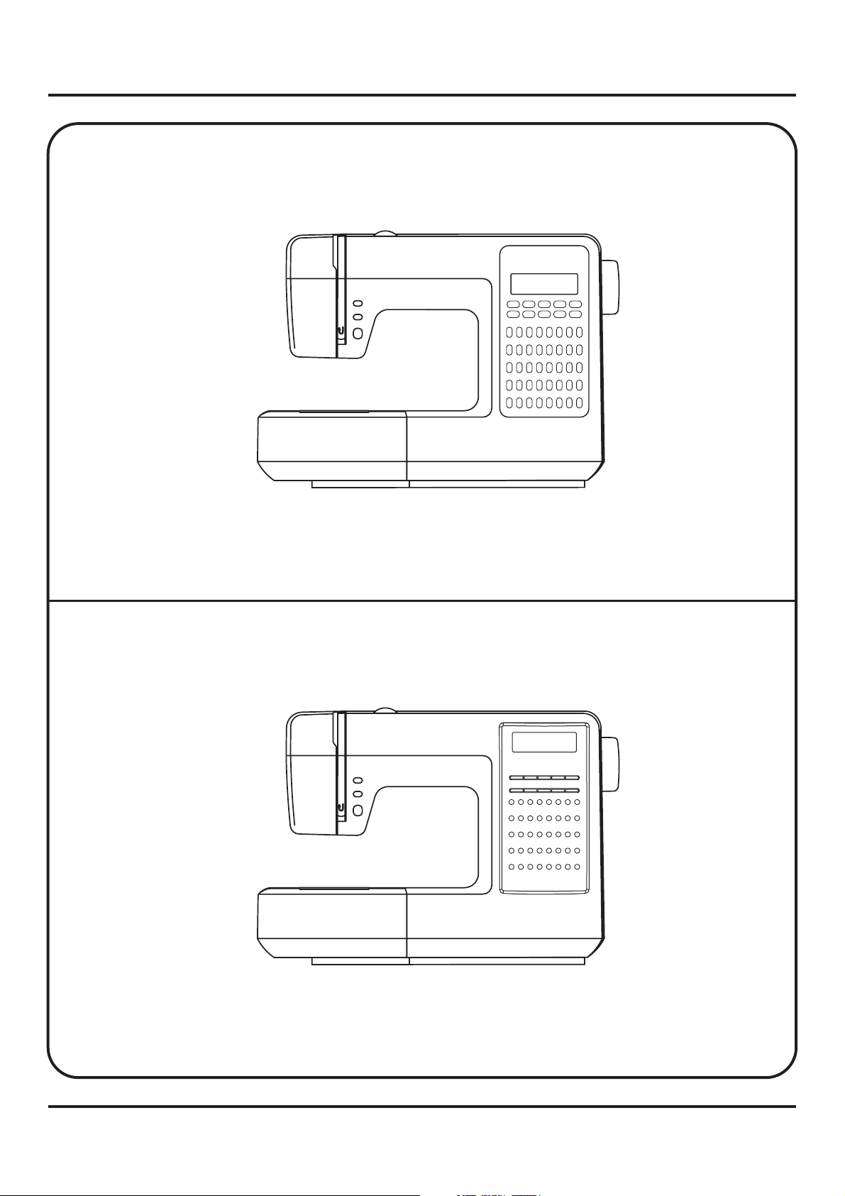
2. Out look
Model 9300A
5
1234
11
9
10
12 13 14 15 16
17
18 19 20 21 22 23 24
28 29
25 26
27
36 37
33 34
35
7
6
30 31 32
38 39 40
8
Model 9300A2
3
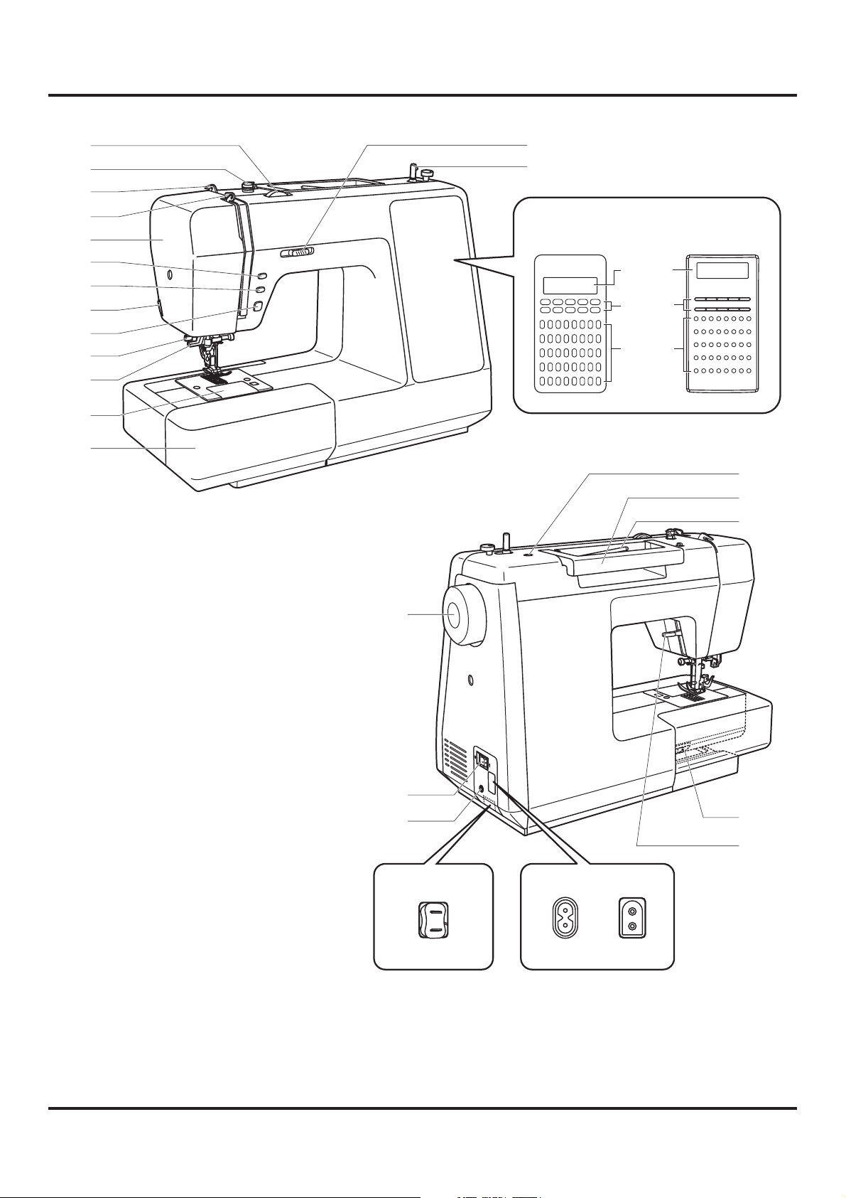
3. Names of principal parts
1
2
3
4
5
6
7
8
9
10
11
12
13
1. Tension dial
14
15
Model
9300A
1234
9
10
17
18 19 20 21 22 23 24
25 26
33 34
11
12 13 14 15 16
28 29
27
36 37
35
Model
9300A2
16 (A)
6
30 31 32
38 39 40
7
8
17 (B)
18 (C)
5
23
24
25
2. Bobbin thread guide
3. Upper thread guide
4. Thread take-up lever
5. Face plate
6. Needle up/down position button
7. Auto-lock button
8. Thread cutter
9. Reverse button
10.Buttonhole lever
11. Auto needle threader
12.Needle plate
13.Sewing table and accessory box
14.Speed limiting adjustment lever
15.Bobbin winder
16.LCD (Liquid crystal display)
17.Function of buttons
18. Stitch selection buttons
19
20
21
22-A 22-B
Eur.
26
27
U.S.A
19. Handwheel
20.Main power switch
21. Foot controller connector
22-A.
Japanese version (automatic
rewinding)
22-B.
European version
USA version
23.Hole for second spool pin
24. Handle
4
25.Horizontal spool
pin
26. Drop feed lever
27.Presser foot lifter
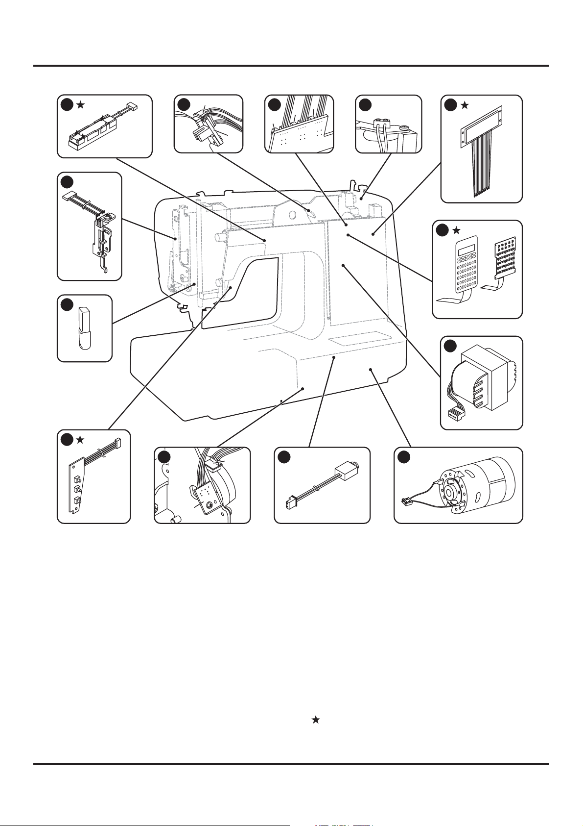
4. lectronic partsNames of e
1
13
12
A
2
3
C
B
4
5
A
B
6
8
7
6
5
4
3
2
6
1
1
5
1
4
1
13
12
11
10
24
9
23
22
1
2
20
9
1
18
32
17
31
30
9
2
28
27
26
0
4
25
39
8
3
7
3
36
35
34
33
9300A2
9300A
7
11
10
B
1.
Slide volume
2-A.
Pulse motor (zigzag)
2-B.
Photo sensor complete (zigzag)
3-A.
Photo sensor complete
(needle position)
3-B.
Photo sensor complete (needle flow)
3-C.
Photo sensor complete (speed)
4.
Bobbin winder micro switch
5. LCD panel
6. Keyboard
7. Transformer
A
9
8
8. DC motor
9. Foot controller connector
10-A.
Pulse motor (stitch length)
10-B.
Photo sensor complete
(stitch length)
11.
Up & down fixed position switch
12. Lamp
13.
Photo sensor complete (B/H)
: Set on the front cover
5
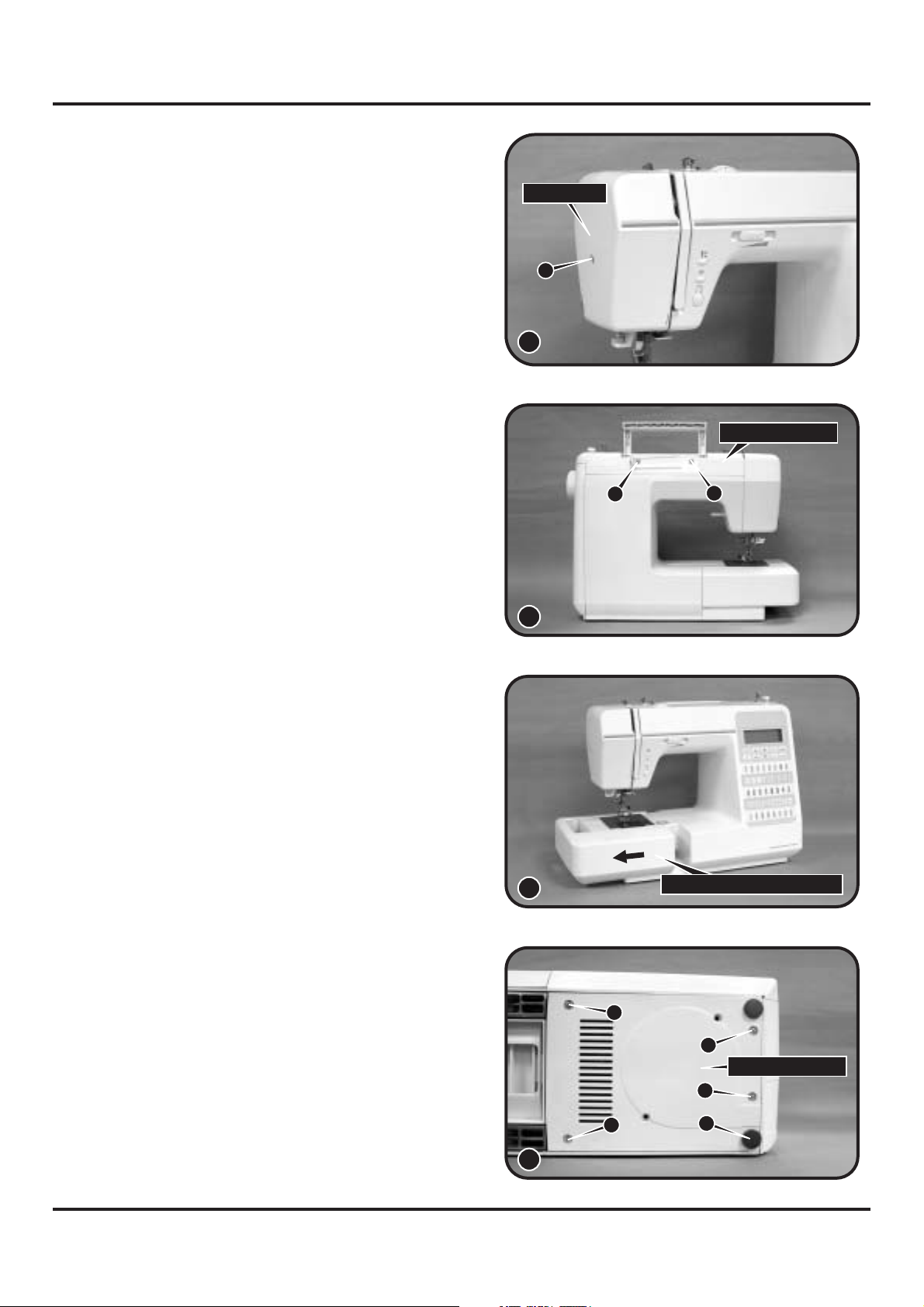
5. Removing methods of external parts
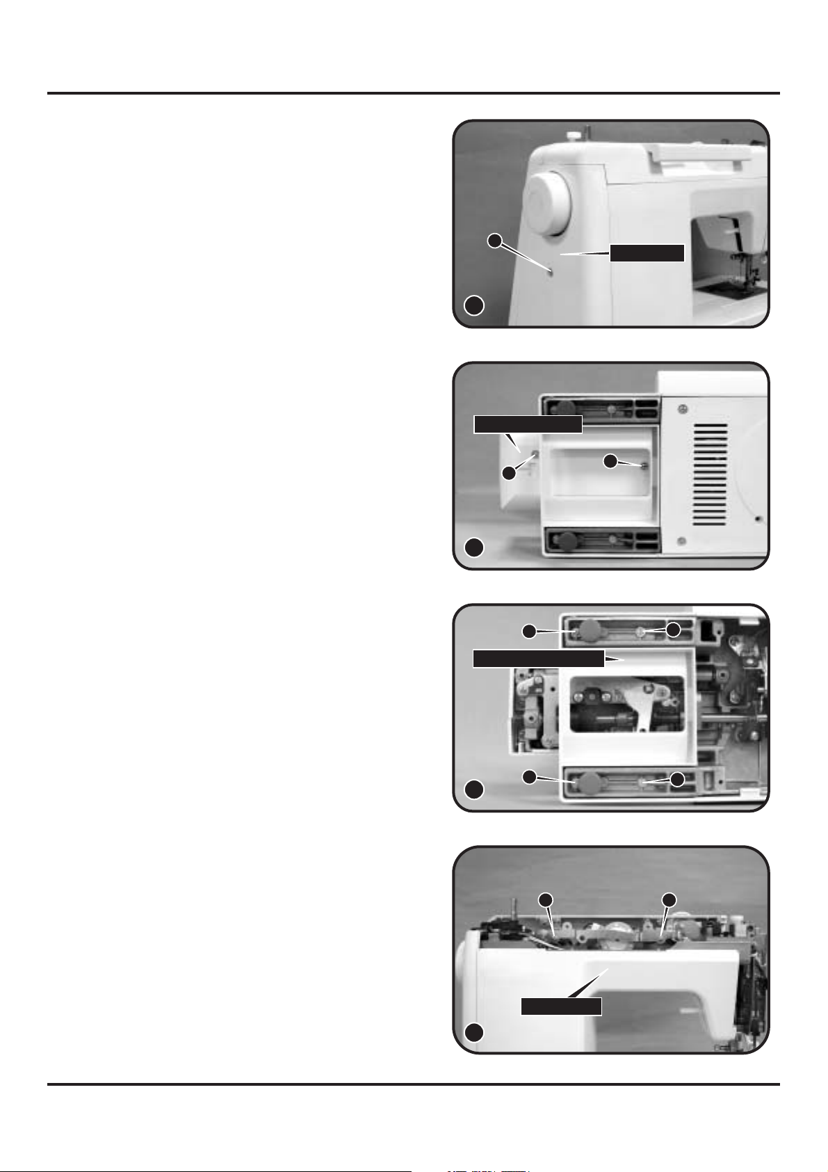
5-1 Face plate
Remove screw (a) and remove the face plate.
(1)
5-2 Arm top cover
Remove 2 screws (b, c) and remove the arm
top cover. (2)
Face plate
a
1
2
Arm top cover
b
c
5-3 Sewing table complete
Keep the snap-in sewing table horizontal, and
pull it in the direction of the arrow. (3)
5-4 Cord reel cover
- Lay down machine. Remove 1 cushion
rubbers (d).
- Remove 4 screws (e, f, g, h). (4)
- Remove cord reel cover.
3
e
f
Sewing table complete
g
Cord reel cover
h
d
4
6
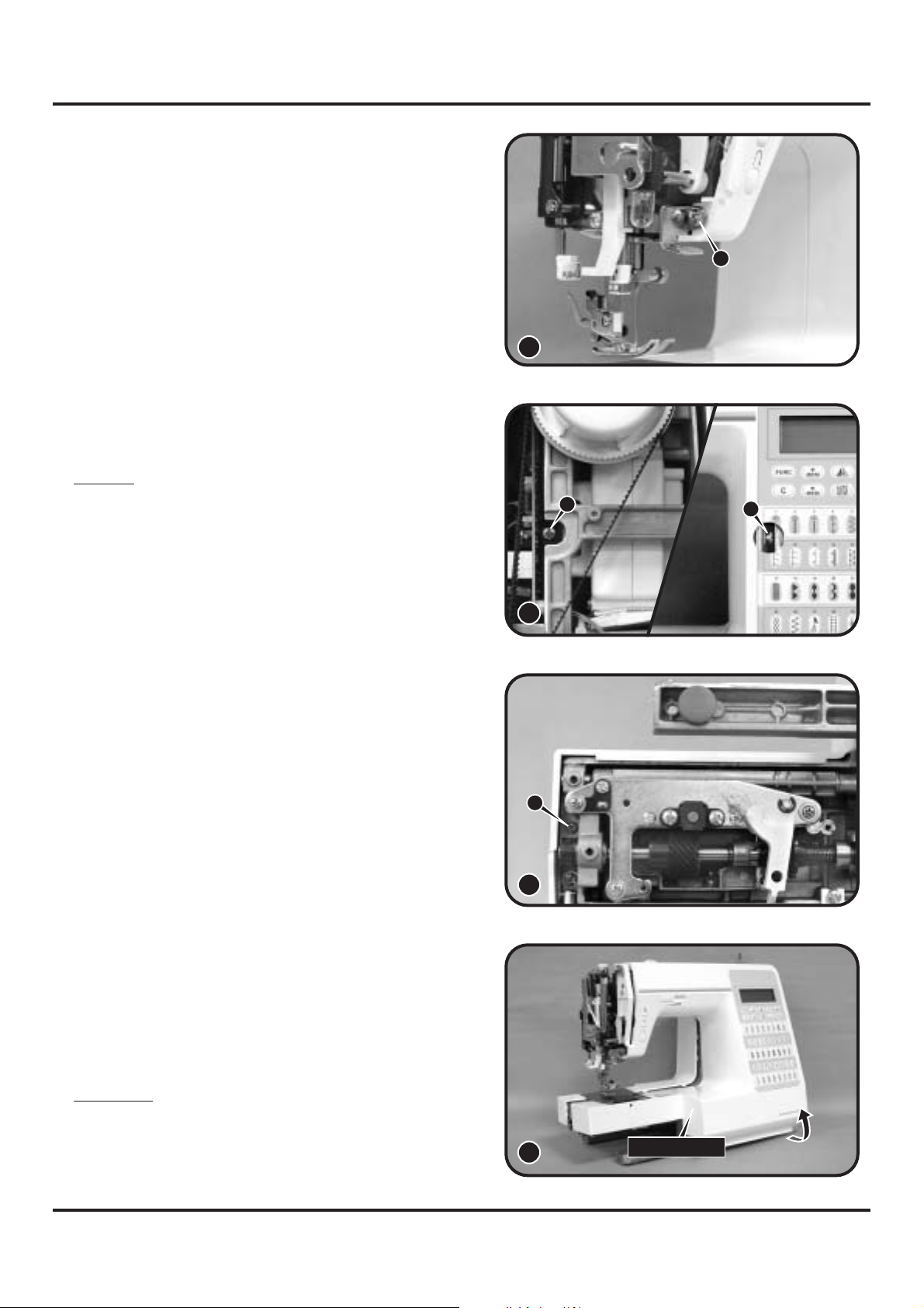
5-5 Belt cover
- Remove screw (i) and remove belt cover. (5)
5-6 Free arm cover
Remove 2 screws (j, k) and remove the free
arm cover. (6)
5-7 Free arm foot bush
Remove 4 screws (l, m, n, o) and remove the
free arm foot bush. (7)
i
5
Free arm cover
j
6
l
Free arm foot bush
Belt cover
k
m
5-8 Front cover
- Remove face plate, arm top cover, sewing
box complete, cord reel cover, belt cover, and
free arm cover and free arm foot bush first.
- Lift handle and remove 2 screws (p, q). (8)
n
o
7
p
Back cover
q
8
7
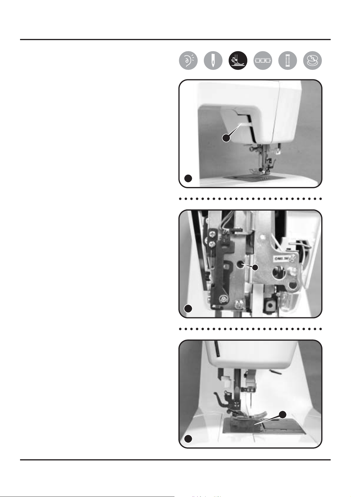
- Loosen screw (r) about 3mm. (9)
- Loosen screw (s) about 3mm. (10)
Note 1:
First using electric torch (flash light) etc to
locate screw (s) position which deeply inside
the machine.
r
9
s
s
- Remove screw (t). (11)
- Remove front cover following direction of
arrow. (12)
10
t
11
Attention:
Be sure to remove the front cover carefully,
because the leader wire and the body are
connected together.
12
Front cover
8
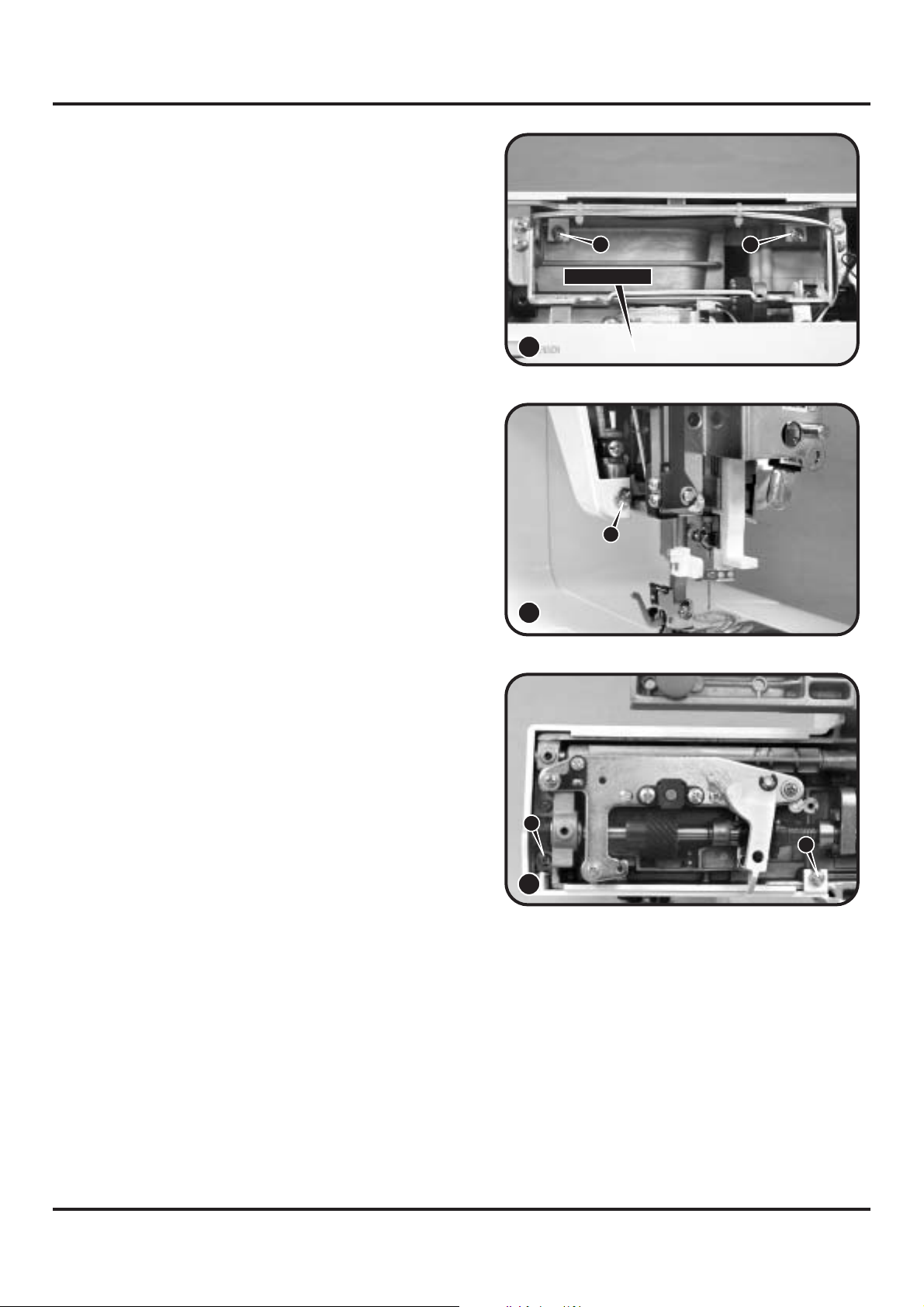
5-9 Back cover
- Remove front cover first.
- Remove 2 screws (u, v). (13)
- Loosen screw (w) about 3mm. (14)
- Remove screw (x).
13
14
u
Back cover
w
v
- Loosen screw (y) about 3mm.
- Remove the back cover. (15)
x
y
15
9

6. Adjusting methods of each part
6-1 Symbol instructions
Noise occur while the machine is running.
Skip-over stitching, needle breakage, and problems associated with needle.
Delivery of cloth to be in disorder and insufficient, problems associated with delivery
amount.
Stitch tightening problem.
BH right and left stitching is not even, incorrect length and problems associated with
buttonhole sewing.
Bobbin winding problem.
10
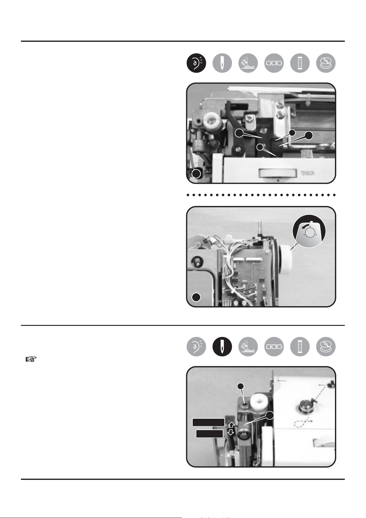
6-2 Play of arm shaft
1) Remove the face plate and arm top
cover.
2) Remove the 2 screws (a, b) of arm shaft
collar (A). (1)
3) Pull hand wheel backward.
4) Push arm shaft collar (A) to left tightly
against arm shaft bushing (B), and then
fasten and secure screws (a, b). (1)
B
b
a
A
5) Be sure proper distance between arm
shaft collar and arm shaft bushing. (2)
6) Be sure arm shaft operates smoothly
after adjustment.
7) Arm shaft collar and arm shaft bushing
being too tightly closed might cause
insufficient operation of arm shaft.
8) Follow step 1, 2, 3 in order to re-adjust.
6-3 Drop middle point of needle
1
2
- Choose patterns #1.
1) Remove face plate.
2) Loosen screw (a) of needle bar
supporter.
3) Turn needle bar supporter (A) forward /
backward to adjust needle.
Backward = to move needle forward
Forward = to move needle backward
4) Set needle position above center of
needle plate and fasten screw (a).
a
A
backward
forward
11
6-4 Height of presser foot
1) Remove face plate and lift up presser
bar lifter lever (A). (1)
2) Loosen screw (a) of presser bar bracket.
(2)
3) Place gauge (B) (6.0~6.2mm) on top of
needle plate. (3)
4) Pull down presser bar lifter lever so
bottom of presser foot and top surface
of gauge would meet.
A
5) Secure tightly screw (a).
6) The correct setting of gauge should be
6.0~6.2mm.
1
a
2
12
B
3
 Loading...