

Page 1
The appliance is not intended for use by young children
3/08/2017
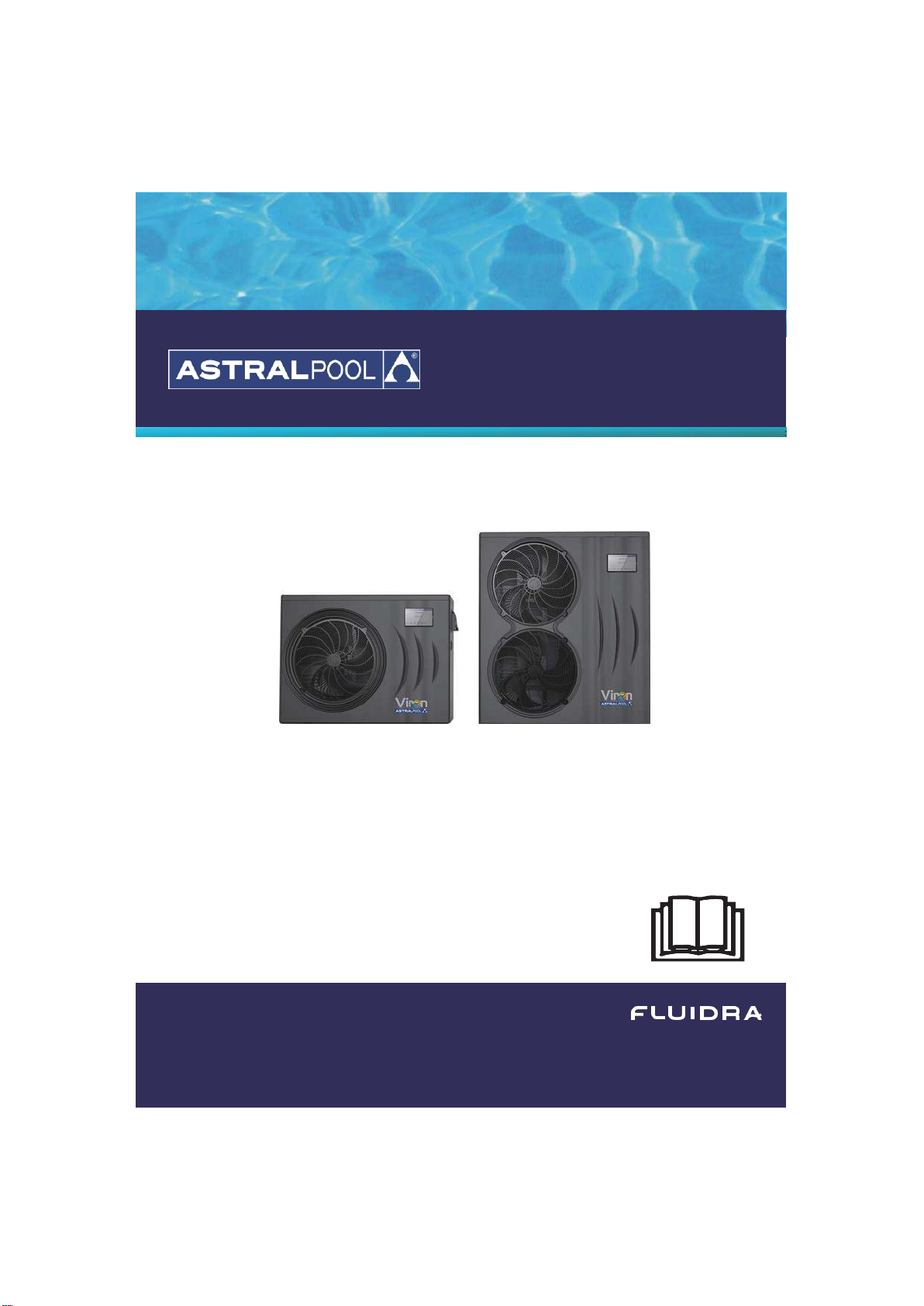
VIRON RANGE
INVERTER HEAT PUMPS
Installation & Instruction manual
INSTALLATION AND OPERATING INSTRUCTIONS
I
INSTALLATION AND OPERATING INSTRUCTIONS
Viron Range
Inverter Heat Pumps
Page 2

Page 3
CONTENTS
1. Preface
1
2.
Specifications
4
2.1
Performance Data of Swimming Pool Heat Pump Unit
4
2.2
Dimensions for Swimming Pool Heat Pump Unit
7
3.
Installation and Connection
9
3.1 Installation illustration
9
3.2 Swimming Pool Heat Pumps Location
10
3.3 How Close to Your Pool?
10
3.4 Swimming Pool Heat Pumps Plumbing
11
3.5 Swimming Pool Heat Pumps Electrical Wiring
12
3.6 Initial Start-up of the Unit
12
4. Operation and Use
13
4.1 Color screen wire controller interface introduction
13
4.2 Color screen wire controller function introduction
14
4.3 Parameter list and breakdown table
21
4.4 Interface drawin
23
5. Maintenance and Inspection
28
6.Appendix
33
6.1 Cable specification
33
6.2
Comparison table of refrigerant saturation temperature
34
Page 4
1. PREFACE
In order to provide our customers with quality, reliability and versatility, this product has
been made to strict production standards. This manual includes all the necessary
information about installation, debugging, discharging and maintenance. Please read this
manual carefully before you open or maintain the unit. The manufacture of this product will
not be held responsible if someone is injured or the unit is damaged, as a result of
improper installation, debugging, or unnecessary maintenance. It is vital that the
instructions within this manual are adhered to at all times. The unit must be installed by
qualified personnel.
The unit can only be repaired by qualified installer centre , personnel or an authorised dealer.
Maintenance and operation must be carried out according to the recomended time and
frequency, as stated in this manual.
Use genuine standard spare parts only.
Failure to comply with these recommendations will invalidate the warranty.
Swimming Pool Heat Pump Unit heats the swimming pool water and keeps the temperature
constant. For split type unit, The indoor unit can be Discretely hidden or semi-hidden to
suit a luxury house.
Our heat pump has following characteristics:
1 Durable
The heat exchanger is made of PVC & Titanium tube which can withstand prolonged
exposure to swimming pool water.
2 Installation flexibility
The unit can be installed outdoors.
3 Quiet operation
The unit comprises an efficient rotary/ scroll compressor and a low-noise fan motor, which
guarantees its quiet operation.
4 Advanced controlling
The unit includes micro-computer controlling, allowing all operation parameters to be
set. Operation status can be displayed on the LCD wire controller. Remote controller can be chosen
as future option.
WARNING
Do not use means to accelerate the defrosting process or to clean,
Other than those recimmended by the manufacturer.
The appliance shall be stored in a room without continuously
operating ignition sources (for example:open flames, an operating gas
appliance or an operating electric heater.)
Do not pierce or burn.
Be aware that refrigerants may not contain an odour,
Appliance shall be installed,operated and stored in a room with a floor area larger than X .
NOTE The manufacturer may provide other suitable examples or may provide additional
information about the refrigerant odour.
1
Page 5

2
1. PREFACE
This appliance can be used by children aged from 8 years and above and persons
with reduced physical, sensory or mental capabilities or lack of experience and
knowledge if they have been given supervision or instruction concerning use of the
appliance in a safe way and understand the hazards involved. Children shall not pl ay with
the appliance. Cleaning and user maintenance shall not be made by children without
supervision.
If the supply cord is damaged, it must be replaced by the manufacturer, its service agent or
similarly qualified persons in order to avoid a hazard.
The appliance shall be installed in accordance with national wiring regulations.
Do not operate your air conditioner in a wet room such as a bathroom or laundry room.
Before obtaining access to terminals, all supply circuits must be disconnected.
An all-pole disconnection device which has at least 3mm clearances in all pole
have a leakage current that may exceed 10mA residual current device (RCD) having
a rated residual operating current not exceeding 30mA
disconnection must be
incorporated in the fixed wiring in accordance with the wiring rules
Do not use means to accelerate the defrosting process or to clean, other than those recommended
by the manufacturer
The appliance shall be stored in a room without continuously operating ignition sources (for
example: open flames, an operating gas appliance or an operating electric heater.)
Do not pierce or burn
Appliance shall be installed, operated and stored in a room with a floor area larger than X
m2
Be aware that refrigerants may not contain an odour.
The installation of pipe-work shall be kept to a minimum X m2
Spaces where refrigerant pipes shall be compliance with national gas regulations.
Servicing shall be performed only as recommended by the manufacturer.
The appliance shall be stored in a well-ventilated area where the room size corresponds to the
room area as specified for operation.
All working procedure that affets safety means shall only be carried by competent persons.
Transport of equipment containing flammable refrigerants
Compliance with the transport regulations
Marking of equipment using signs
Compliance with local regulations
Disposal of equipment using flammable refrigerants
Compliance with national regulations
Storage of equipment/appliances
The storage of equipment should be in accordance with the manufacturer's instructions. Storage
of packed (unsold) equipment
Storage package protection should be constructed such that mechanical damage to the
equipment inside the package will not cause a leak of the refrigerant charge.
The maximum number of pieces of equipment permitted to be stored together will be
determined by local regulations.
Page 6

3
1. PREFACE
Caution & Warning
1. The unit can only be repaired by qualified installer centre personnel or an authorised
dealer. for Europe market
2. This appliance is not intended for use by persons (including children) with reduced physical
sensory or mental capabilities, or lack of experience and knowledge, unless they have been
given supervision or instruction concerning use of the appliance by a person responsible for
their safety. for Europe market
Children should be supervised to ensure that they do not play with the appliance.
3. Please make sure that the unit and power connection have good earthing, otherwise may
cause electrical shock.
4. If the supply cord is damaged, it must be replaced by the manufacturer or our service agent
or similarly qualified person in order to avoid a hazard.
5. Directive 2002/96/EC (WEEE):
The symbol depicting a crossed-out waste bin that is underneath the appliance indicates that
this product, at the end of its useful life, must be handled separately from domestic waste, must
be taken to a recycling centre for electric and electronic devices or handed back to the dealer
when purchasing an equivalent appliance.
6. Directive 2002/95/EC (RoHs): This product is compliant with directive 2002/95/EC (RoHs)
concerning restrictions for the use of harmful substances in electric and electronic devices.
7. The unit CANNOT be installed near the flammable gas. Once there is any leakage of the gas
, fire can be occur.
8. Make sure that there is circuit breaker for the unit, lack of circuit breaker can lead to
electrical shock or fire.
9. The heat pump located inside the unit is equipped with an over-load protection system. It
does not allow for the unit to start for at least 3 minutes from a previous stoppage.
10. The unit can only be repaired by the qualified personnel of an installer center or an
authorized dealer. for North America market
11. Installation must be performed in accordance with the NEC/CEC by authorized person only.
for North America market
12. USE SUPPLY WIRES SUITABLE FOR 75 .
13. Caution: Single wall heat exchanger, not suitable for potable water connection.
Page 7
4
2.SPECIFICATION
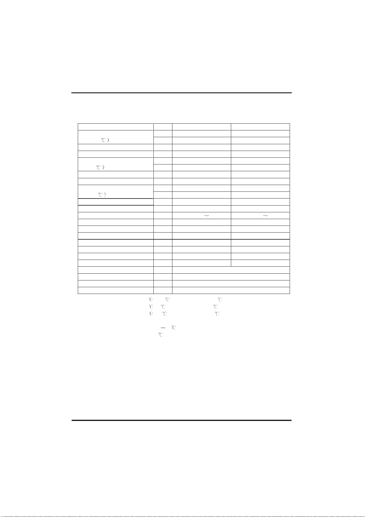
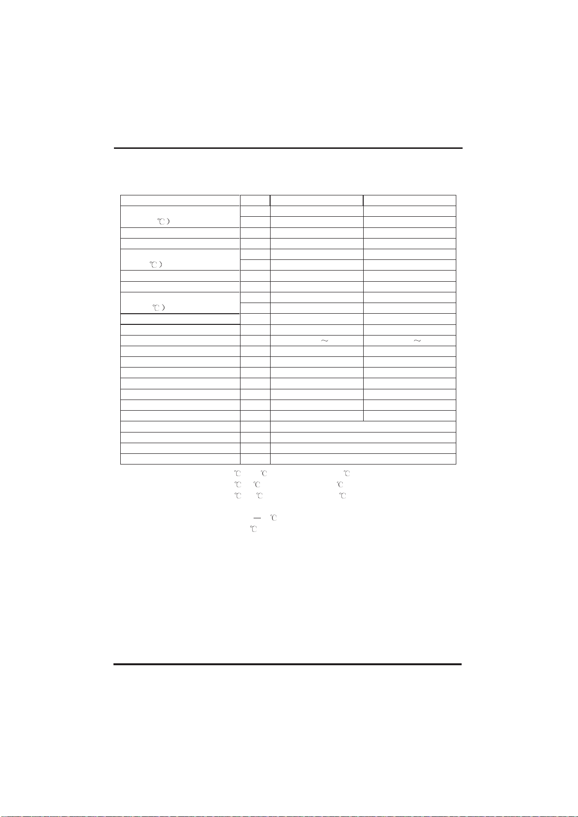
2.1 Performance data of Swimming Pool Heat Pump Unit
*** REFRIGERANT : R32
UNIT
78572
78573
Heating capacity
(27/24.3
kW
2.15~9
2.85~12
Btu/h
7310~30600
9690~40800
Heating Power Input
kW 0.16~1.6
0.21~2.12
COP
13.44~5.63
13.57~5.66
Heating capacity
(15/12
kW 1.75~7.4
2.25~9.7
Btu/h 5950~25160
7650~32980
Heating Power Input
kW 0.25~1.6
0.32~2.08
COP
7~4.63
7.03~4.66
Heating capacity
(10/6.8
kW 1.42~6.1
1.88~8
Btu/h
4828~20740
6392~27200
Heating Power Input
kW
0.25~1.5
0.33~1.95
COP
5.68~4.07
5.7~4.1
Power Supply
220-240V /50Hz
220-240V /50Hz
Compressor Quantity
1
1
Compressor
rotary
rotary
Fan Number
1
1
Noise(1m)
dB(A)
40-50
42-52
Water Connection
mm
48.3 48.3
Water Flow Volume
m3/h
3.2 4.2
Water Pressure Drop(max)
kPa
4 4.5
Unit Net Dimensions(L/W/H)
mm See the drawing of the units
Unit Ship Dimensions(L/W/H)
mm
See package lable
Net Weight
kg
see nameplate
Shipping Weight
kg
see package label
Heating: Outdoor air temp: 27 /24.3 , Inlet water temp:26
Outdoor air temp: 15 /12 , Inlet water temp:26 Outdoor
air temp: 10 /6.8 , Inlet water temp:26
Operating range:
Ambient temperature:-15 43
Water temperature:9-40
Page 8
5
2.SPECIFICATION
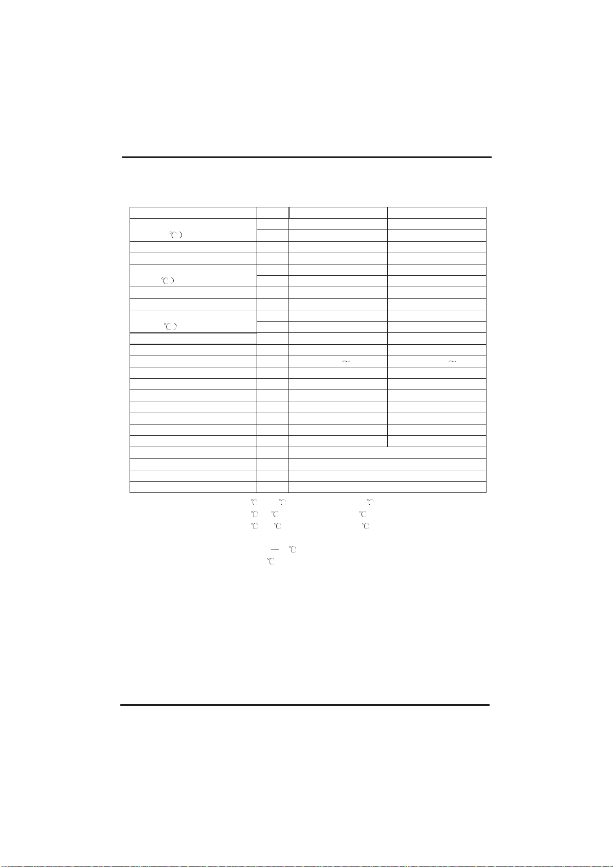
2.1 Performance data of Swimming Pool Heat Pump Unit
*** REFRIGERANT : R32
UNIT
78574
78575
Heating capacity
(27/24.3
kW
3.77~17
4.6~19.5
Btu/h
12818~57800
15640~66300
Heating Power Input
kW 0.3~3.02
0.37~3.94
COP
12.57~5.63
12.43~4.95
Heating capacity
(15/12
kW 2.92~12.4
3.84~15.4
Btu/h 9928~42160
13056~52360
Heating Power Input
kW 0.44~2.86
0.6~3.81
COP
6.64~4.34
6.4~4.04
Heating capacity
(10/6.8
kW 2.5~10.7
3.38~14.4
Btu/h
8500~36380
11492~48960
Heating Power Input
kW
0.45~2.64
0.62~3.62
COP
5.56~4.05
5.45~3.98
Power Supply
220-240V /50Hz
220-240V /50Hz
Compressor Quantity
1
1
Compressor
rotary
rotary
Fan Number
1
1
Noise
dB(A)
44-53
45-56
Water Connection
mm
48.3 48.3
Water Flow Volume
m3/h
5.3 6.6
Water Pressure Drop(max)
kPa
5
6
Unit Net Dimensions(L/W/H)
mm See the drawing of the units
Unit Ship Dimensions(L/W/H)
mm
See package lable
Net Weight
kg
see nameplate
Shipping Weight
kg
see package label
Heating: Outdoor air temp: 27 /24.3 , Inlet water temp:26
Outdoor air temp: 15 /12 , Inlet water temp:26 Outdoor
air temp: 10 /6.8 , Inlet water temp:26
Operating range:
Ambient temperature:-15 43
Water temperature:9-40
Page 9
6
2.SPECIFICATION
2.1
Performance data of Swimming Pool Heat Pump Unit
*** REFRIGERANT : R32
UNIT
78576
78577
Heating capacity
(27/24.3
kW
5.7~24.2
6.7~28.3
Btu/h
19380~82280
22780~96220
Heating Power Input
kW 0.46~4.8
0.54~5.57
COP
12.39~5.04
12.41~5.08
Heating capacity
(15/12
kW 4.68~19.9
5.46~23.3
Btu/h 15912~67660
18564~79220
Heating Power Input
kW 0.72~4.74
0.83~5.49
COP
6.5~4.2
6.58~4.24
Heating capacity
(10/6.8
kW 4.2~17.8
4.9~20.8
Btu/h
14280~60520
16660~70720
Heating Power Input
kW
0.75~4.4
0.87~5.1
COP
5.6~4.05
5.63~4.08
Power Supply
220-240V /50Hz
380-415V/3N /50Hz
Compressor Quantity
1
1
Compressor
rotary
rotary
Fan Number
2
2
Noise
dB(A)
46-57
48-58
Water Connection
mm
48.3 48.3
Water Flow Volume
m3/h
8.6 10
Water Pressure Drop(max)
kPa
11 15
Unit Net Dimensions(L/W/H)
mm See the drawing of the units
Unit Ship Dimensions(L/W/H)
mm
See package lable
Net Weight
kg
see nameplate
Shipping Weight
kg
see package label
Heating: Outdoor air temp: 27 /24.3 , Inlet water temp:26
Outdoor air temp: 15 /12 , Inlet water temp:26 Outdoor
air temp: 10 /6.8 , Inlet water temp:26
Operating range:
Ambient temperature:-15 43
Water temperature:9-40
Page 10
7
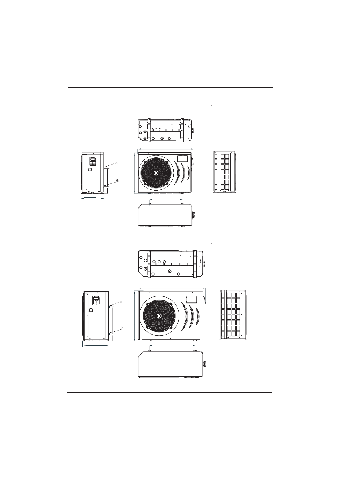
2.SPECIFICATION
2.2
The dimensions for Swimming Pool Heat Pump Unit
UNIT: 78572/78573
unit mm
1046
615
UNIT: 78574/78575
unit mm
1161
790
Water outlet
48.3
Water inlet
48.3
470
Water outlet
48.3
Water inlet
48.3
435
110
350
97
465
768
862.5
Page 11
8
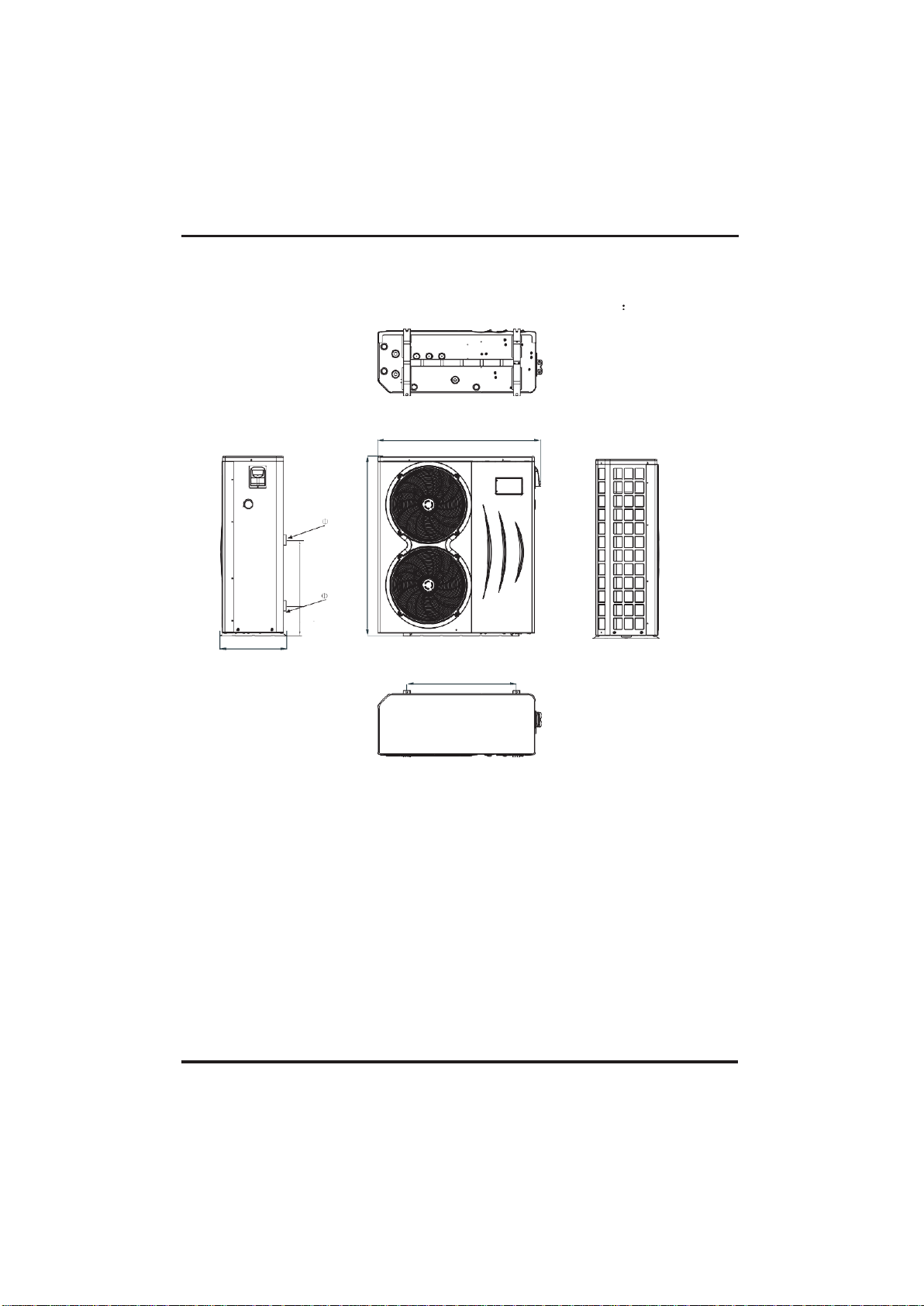
2.SPECIFICATION
2.2 The dimensions for Swimming Pool Heat Pump Unit
UNIT: 78576/78577
1161
775
unit mm
Water outlet
48.3
Water inlet
48.3
470
97
550
1274
Page 12
9
3.
INSTALLATION AND CONNECTION
3.1
Installation illustration
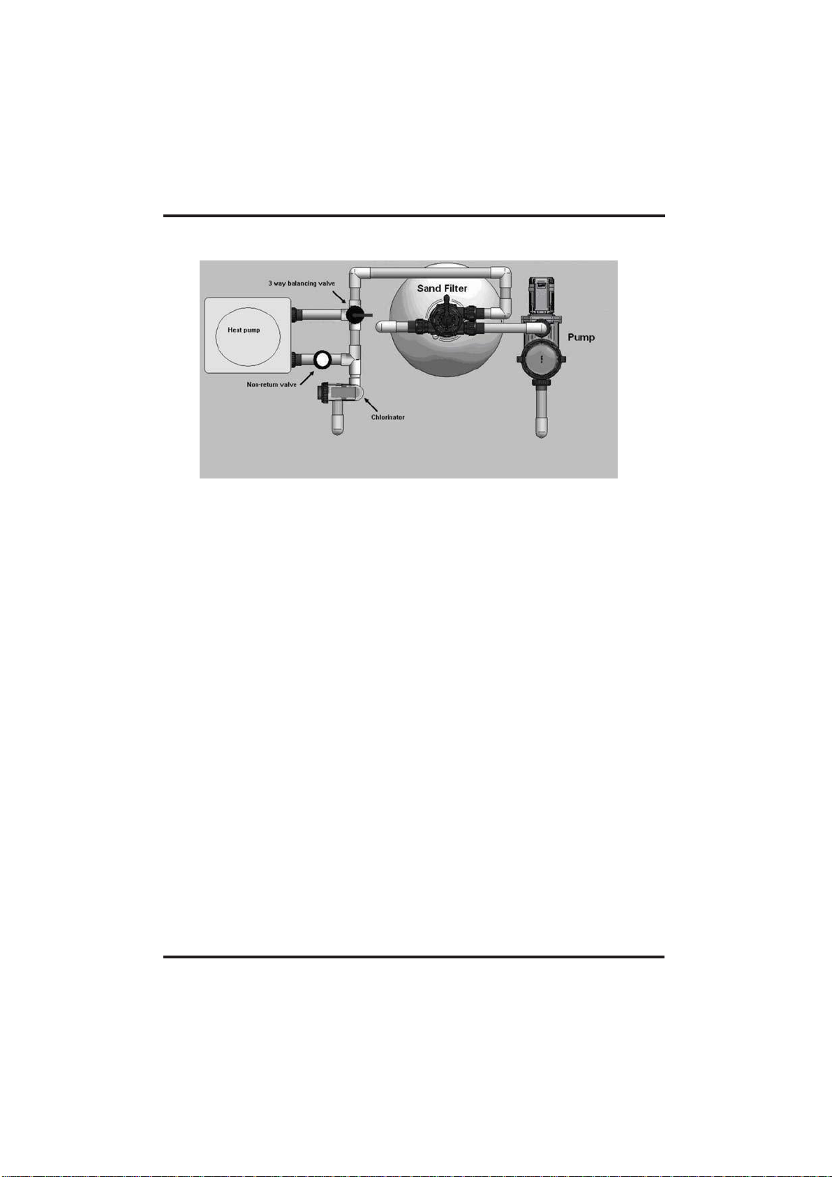
Installation items:
The factory only provides the main unit and the water unit; the other items in the illustration
are necessary spare parts for the water system ,that provided by users or the installer.
Attention:
Please follow these steps when using for the first time
1.Open valve and charge water.
2. Make sure that the pump and the water-in pipe have been filled with water.
3.Close the valve and start the unit.
ATTN: It is necessary that the water-in pipe is higher than the pool surface.
The schematic diagram is for reference only. Please check the water inlet/outlet label on the
heat pump while plumbing installation.
The schematic diagram is for reference only. Please check the water inlet/outlet label on the
heat pump while plumbing installation.
The controller is mounted on the wall
IMPORTANT NOTE:
A W ATER BY-PASS MUST BE PLUMBED TO REGULATE WATER FLOW TO HEAT PUMP.
FAILURE TO DO SO MAY RESULT IN POOR EFFICIENCY A ND REDUCED HEATING OUTPUT.
Page 13
3.
INSTALLATION AND CONNECTION
3.2
Swimming Pool Heat Pumps Location
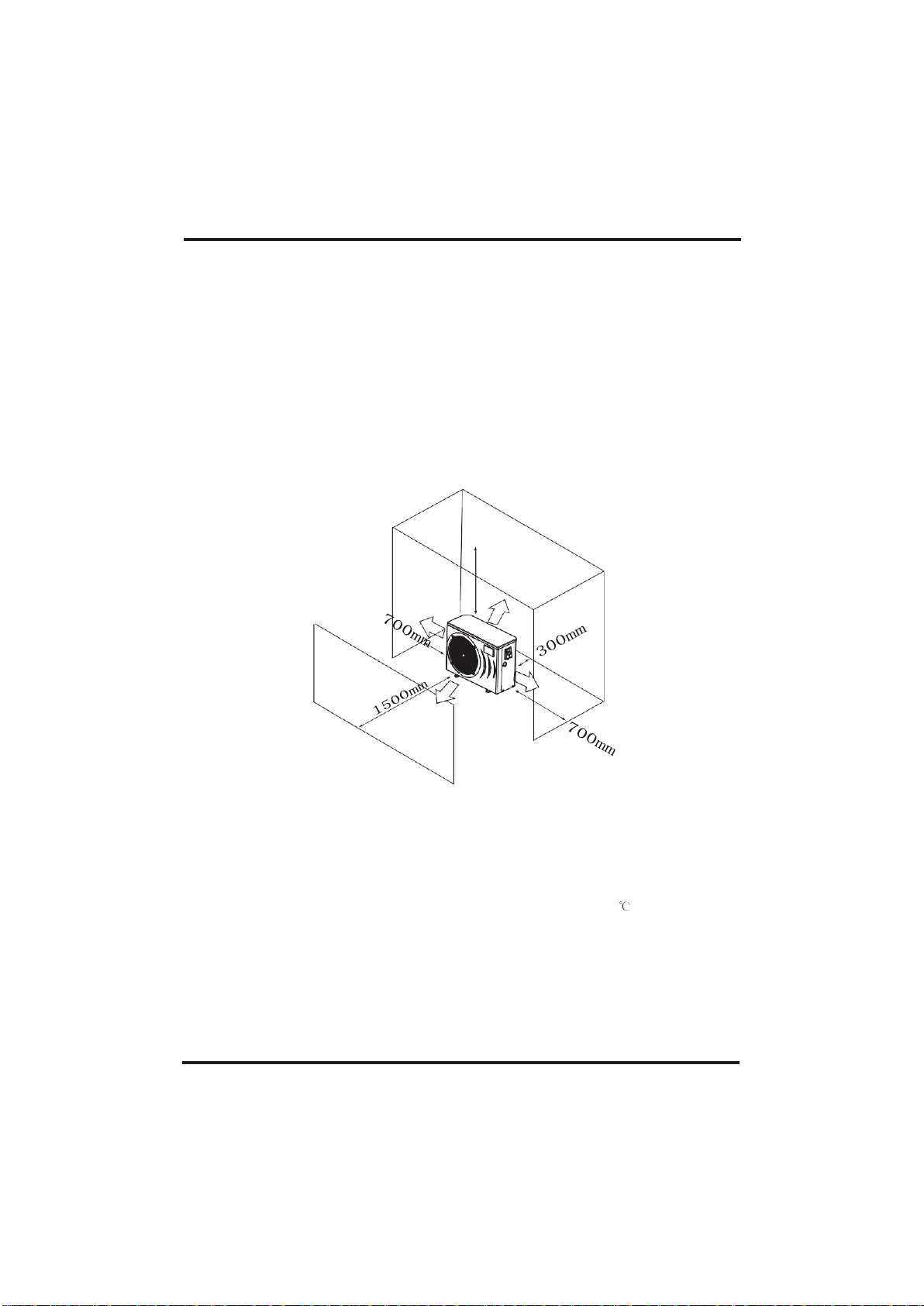
The unit will perform well in any outdoor location provided that the following three factors are
presented:
1. Fresh Air - 2. Electricity - 3. Pool filter piping
The unit may be installed virtually anywhere outdoors. For indoor pools please consult the
supplier. Unlike a gas heater, it has no draft or pilot light problem in a windy area.
DO NOT place the unit in an enclosed area with a limited air volume, where the units
discharge air will be re-circulated.
DO NOT place the unit to shrubs which can block air inlet. These locations deny the unit of a
continuous source of fresh air which reduces it efficiency and may prevent adequate heat
delivery.
3.3
How Close To Your Pool?
Normally, the pool heat pump is installed within 7.5 metres of the pool. The longer the
distance from the pool, the greater the heat loss from the piping. For the most part ,the piping is
buried. Therefore, the heat loss is minimal for runs of up to15 meters(15 meters to and from the pump
= 30 meters total), unless the ground is wet or the water table is high. A very rough
estimate of heat loss per 30 meters is 0.6 kW-hour,(2000BTU) for every 5 difference in
temperature between the pool water and the ground surrounding the pipe, which translates to about
3% to 5% increase in run time.
10
Air inlet
Air outlet
500mm
Page 14
3.INSTALLATION AND CONNECTION
3.4
Swimming Pool Heat Pumps Plumbing
The Swimming Pool Heat Pumps exclusive rated flow titanium heat exchanger requires no
special plumbing arrangements except bypass(please set the flow rate according to the
nameplate). The water pressure drop is less than 10kPa at max. Flow rate. Since there is no
residual heat or flame Temperatures, The unit does not need copper heat sink piping. PVC
pipe can be run straight into the unit.
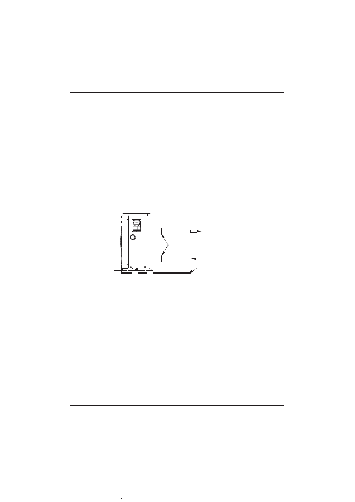
Location: Connect the unit in the pool pump discharge (return) line downstream of all filter
and pool pumps, and upstream of any chlorinators, ozonators or chemical pumps.
Standard model have slip glue fittings which accept 32mm or 50 mm PVC pipe for
connection to the pool or spa filtration piping. By using a 50 NB to 40NB you can plumb 40NB
Give serious consideration to adding a quick coupler fitting at the unit inlet and outlet to allow
easy draining of unit for winterizing and to provide easier access should servicing be
required.
To pool
PVC COUPLER
RECOMMENDED(Provided)
From pump
CONDENSATION
DRAIN
BARB FTG
Condensation: Since the Heat pump cools down the air about 4-5 ℃ , water may condense on
the fins of the horseshoe shaped evaporator. If the relative humidity is very high, this could
be as much as several litres an hour. The water will run down the fins into the basepan and
drain out through the barbed plastic condensation drain fitting on the side of the basepan.
This fitting is designed to accept 20mm clear vinyl tubing which can be pushed on by hand
and run to a suitable drain. It is easy to mistake the condensation for a water leak inside the
unit.
NB: A quick way to verify that the water is condensation is to shut off the unit and keep the
pool pump running. If the water stops running out of the basepan, it is condensation. AN
EVEN QUICKER WAY IS to TEST THE DRAIN WATER FOR CHLORINE - if the is no chlorine
present, then it's condensation.
IMPORTANT N OTE:
A WA TER BY-PASS MUST BE PLUMBED TO REGULATE WA TER F LOW TO HEAT PUMP.
FAILURE TO D O SO MAY RESULT IN POOR EFFICIENCY AND REDUCED HEATING OUTPUT.
11
Page 15

3.INSTALLATION AND CONNECTION
3.5
Swimming Pool Heat Pumps Electrical Wiring
NOTE: Although the unit heat exchanger is electrically isolated from the rest of the unit, it
simply prevents the flow of electricity to or from the pool water. Grounding the unit is still
required to protect you against short circuits inside the unit. Bonding is also required.
The unit has a separate molded-in junction box with a standard electrical conduit nipple
already in place. Just remove the screws and the front panel, feed your supply lines in
through the conduit nipple and wire-nut the electric supply wires to the three connections
already in the junction box (four connections if three phase). To complete electrical hookup, connect
Heat Pump by electrical conduit, UF cable or other suitable means as specified (as permitted by
local electrical authorities) to a dedicated AC power supply branch circuit
equipped with the proper circuit breaker, disconnect or time delay fuse protection.
Disconnect - A disconnect means (circuit breaker , fused or un-fused switch) should be
located within sight of and readily accessible from the unit, This is common practice on
commercial and residential air conditioners and heat pumps. It prevents remotely-energizing
unattended equipment and permits turning off power at the unit while the unit is being
serviced.
3.6
Initial startup of the Unit
NOTE- In order for the unit to heat the pool or spa, the filter pump must be running to
circulate water through the heat exchanger.
Start up Procedure - After installation is completed, you should follow these steps:
1. Turn on your filter pump. Check for water leaks and verify flow to and from the pool.
2. Turn on the electrical power supply to the unit, then press the key ON/OFF of wire
controller, It should start in several seconds.
3. After running a few minutes make sure the air leaving the top(side) of the unit is
cooler(Between 5-10 )
4. With the unit operating turn the filter pump off. The unit should also turn off automatically,
5. Allow the unit and pool pump to run 24 hours per day until desired pool water temperature
is reached. When the water-in temperature reaches this setting, the unit will slow down for a
period of time, if the temperature is maintained for 45 minutes the unit will turn off. The unit
will now automatically restart (as long as your pool pump is running)when the pool
temperature drops more than 0.2 below set temperature.
Time Delay- The unit is equipped with a 3 minute built-in solid state restart delay included to protect
control circuit components and to eliminate restart cycling and contactor chatter.
This time delay will automatically restart the unit approximately 3 minutes after each control circuit
interruption. Even a brief power interruption will activate the solid state 3 minute
restart delay and prevent the unit from starting until the 5 minute countdown is completed.
12
Page 16
4. Operationanduse
4.1
Color screen wire controller interface introduction
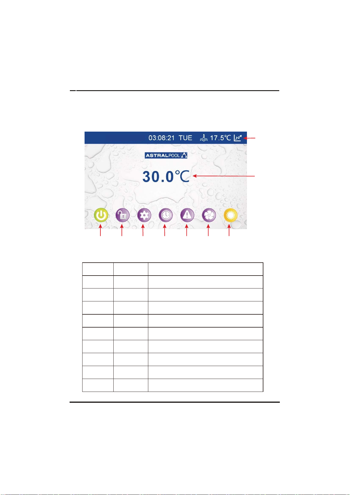
4.1.1Maininterface
⑨
⑧
4.1.2 Button Description
NO.
Name
The button function
①
ON/OFF
Press to start /shut off the unit
②
LOCK
Click to lock the screen ,Input "22" to unlock the
screen by press the "lock button"
③
Parameter
Click this button to view the unit state
and the
parameter
④
CLOCK
Press to set the clock,
the timer on or timer off
⑤
Fault display
Click to view fault history
⑥
Silent setting
Click to turn on/off silent function and to
set
timing
Low speed function.
⑦
MODE
Click to enter the mode switch interface
⑧
Water
Inlet Temp.
Click to enter mode setting and the
target
temp. Setting interface
⑨
Temp. curve
Click to view the temp. and power curve
13
09 DEC 2017
①
②
③
④
⑤
⑥
⑦
Page 17
4.Operationanduse
4.2
Color screen wire controller function introduction
4.2.1
Booting and shutdown
As shown in figure 1.1:
In shutdown status, click ① then the unit will be booted
In booting status, click ① then the unit will be shut down.
4.2.2
Mode switch and target temperature Setting
2.2 1 Mode switch
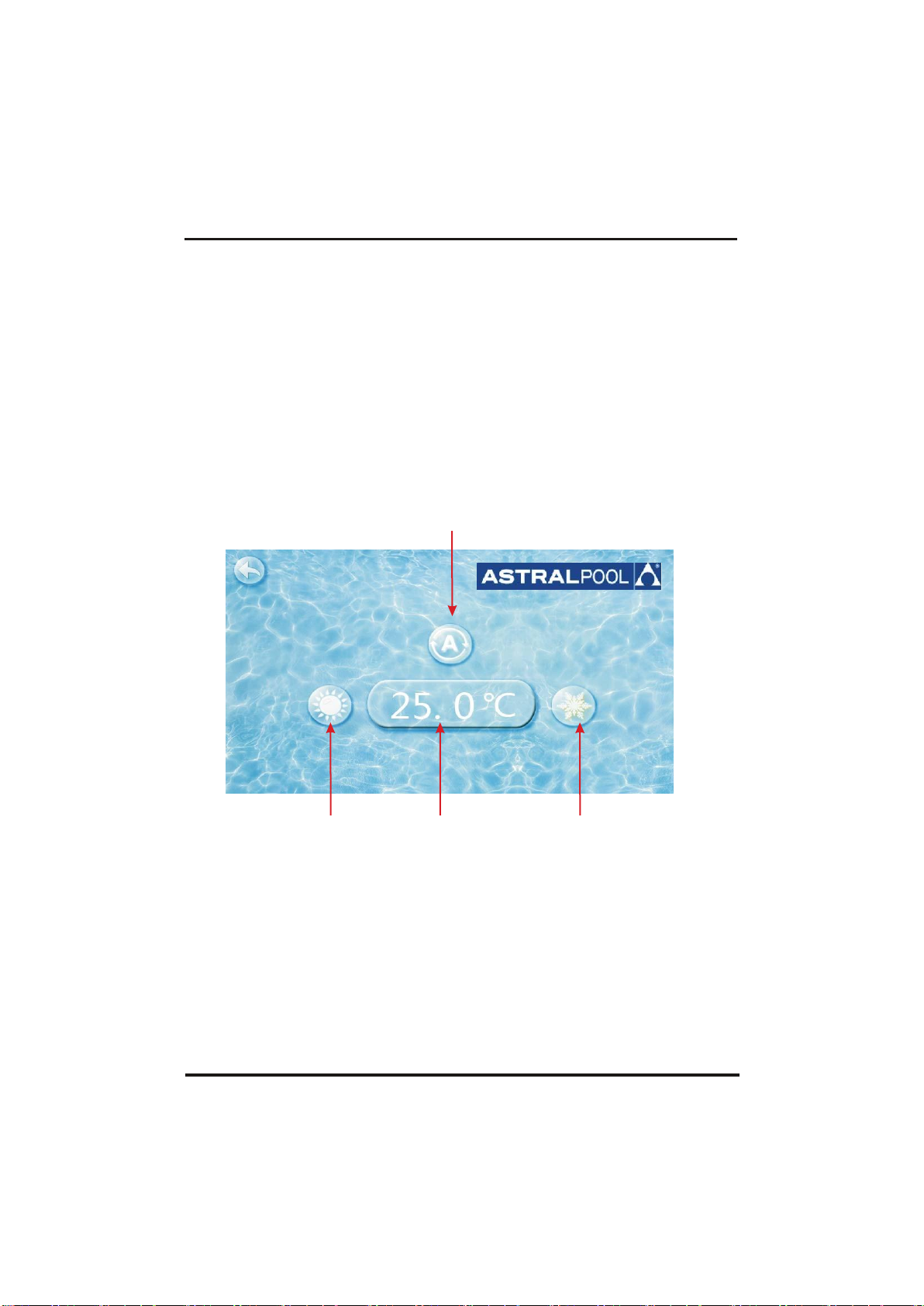
In the main interface, click mode button or inlet water temperature setting
button, interface displays as follows:
②
③ ④ ①
Click the refrigeration mode button ①, automatic mode button② or
heating mode button ③then you can select the corresponding mode.
Note: when the unit is designed for single automatic mode or single
thermal mode, the mode can not be switched.
2.2.2Target temp. setting
Clice the temperature set button ④,you can set the target temperature.
14
Page 18
15
4.Operationanduse
4.2.3
Clock setting
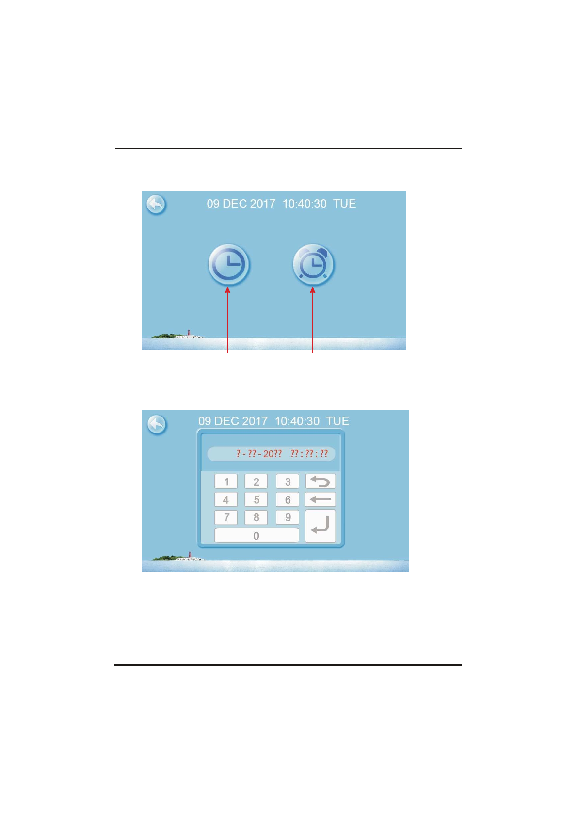
In the main interface, click on the clock Settings button, interface displays as follows:
① ②
2.3.1
The operation of time setting
Click on the time Settings button ① , interface displays as follows:
Click the value to set time directly, the click confirm button to save the
Settings.
For example: setup time: the 30-11-2016 16:00:00, input 30 11 16 16 00 00 , the
time change then click confirm button.
Note: if the input format is not correct, the wrong time will be saved by
clicking confirm button.
Page 19
16
4.Operationanduse
2.3.2
The operation of timing setting
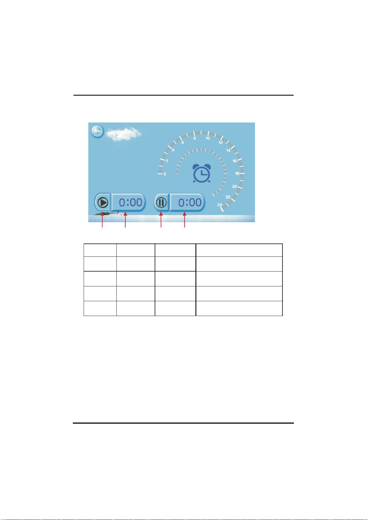
Click the timing set button ② to enter timing setinterface.
① ② ③ ④
NO.
Name
Button
color
Button function
①
Timing start
button
Start: green
End: gray
Click this button to start or end
timing start setting function
②
Timing on
setting
Click to set start time of the timing
③
Timing end
button
Open: red
End: gray
Click this button to start or end
timing end setting function
④
Timing off
setting
Click to set end time of the timing
For example above: without action, 0 o 'clock and 1o 'clock will
be the on and off time of timing settings.
Page 20
17
09 DEC 2017
09 DEC 2017
4.Operationanduse
4.2.4
Silent setting and silent timing setting
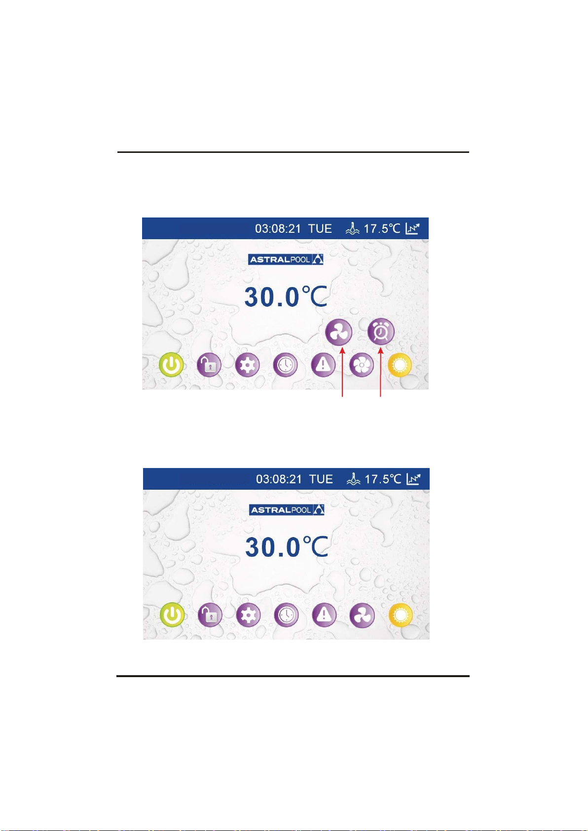
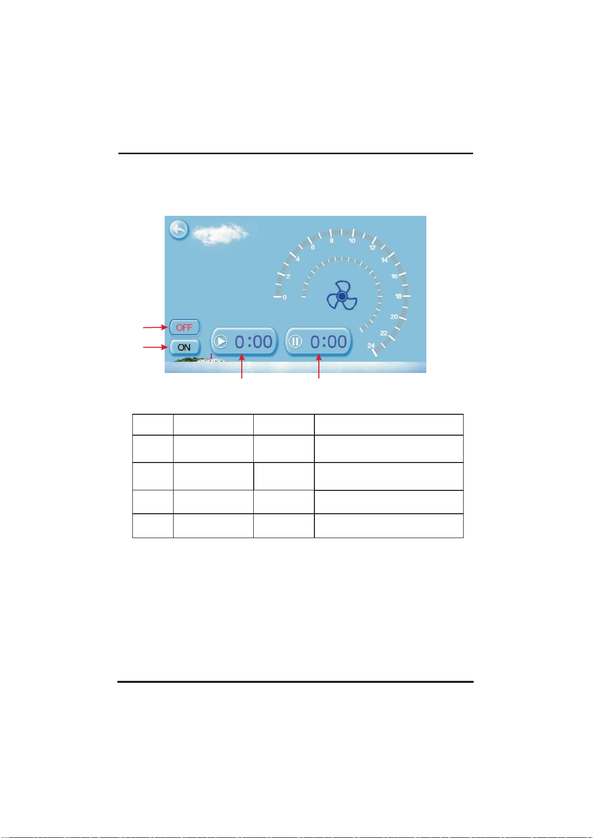
Click the silent setting button ,and the interface displays
as follows:
① ②
2.4.1
The silent button
Click the silent button ①, the unit will enter the silent mode, and
interface displays as follows:
Click the silent button ① again, to exit the silent mode.
Page 21
18
①
②
4.Operationanduse
2.4.2
Timing silent function setting
Click timing silent button ②, and interface displays as follows:
③
④
NO.
Name
Color
Function
①
Timing silent off
Used: red
Unused:gray
Click to use or unuse timing
off function
②
Timing silent on
Use:green
Unused:gray
Click to use or unuse timing
on function
③
Timing silent start
time
Click this button to set the timing
silent start time
④
Timing silent end
time
Click this button to set the timing
silent end time
Start time and end time setting value must be among the range of
0:00-23:00,
and setting value can be precise to hour digit.
For example above, click "ON"to use timing silent,
the unit will start the silent at 0:00 points and end at 4:00;
click "OFF" to unuse the timing silent, but if the unit
is in timing silent mode, it will exit silent timing immediately.
Page 22
19
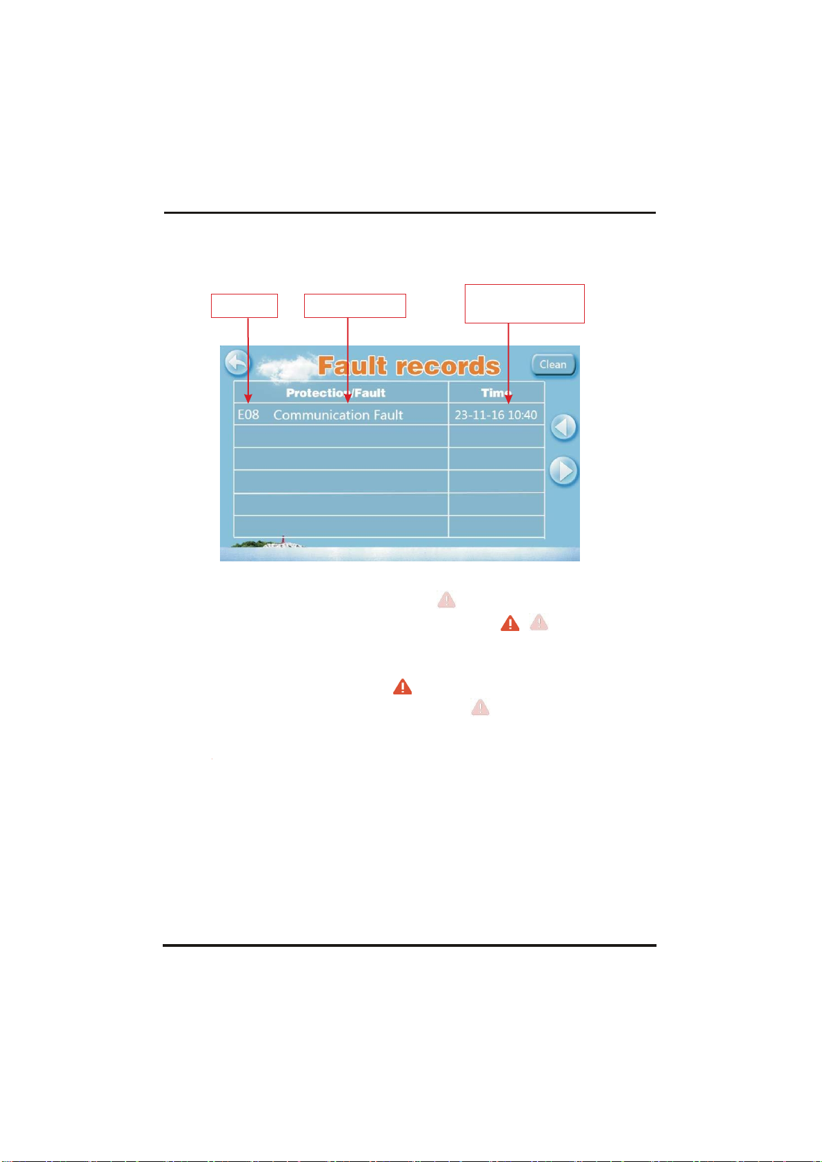
The fault name
Fault code
Fault time
day - month - year
hour:min
4.Operationanduse
4.2.5
History of the fault
In the main interface click fault display key, interface displays as follows:
If no failure, main interface displays static " "
When fault occurs,the fault icon will flash between the " " " ",
the failure interface will record time, code, name of the fault.
After troubleshooting, if you do not check the failure record,
the main interface will display static " "; if you check the
failurerecord, the main interface will displays static "
";
Failure record is in reverse order,according to the happening time.
Press the "Clean" key,you can delete the fault record.
4.2.6
Color Display Calibration
Keep click quickly at the blank area on any interface till you hear a long
beep. Then you will enter the calibration interface. Click "+" to start
calibration.When you hear the beep again, you will finish
calibration and exit.
Remark: the wire controller can display the temperature unit as "℉" or
"℃" according to the unit model you bought.
Page 23
20
4.Operationanduse
4.2.7
Temperature curve
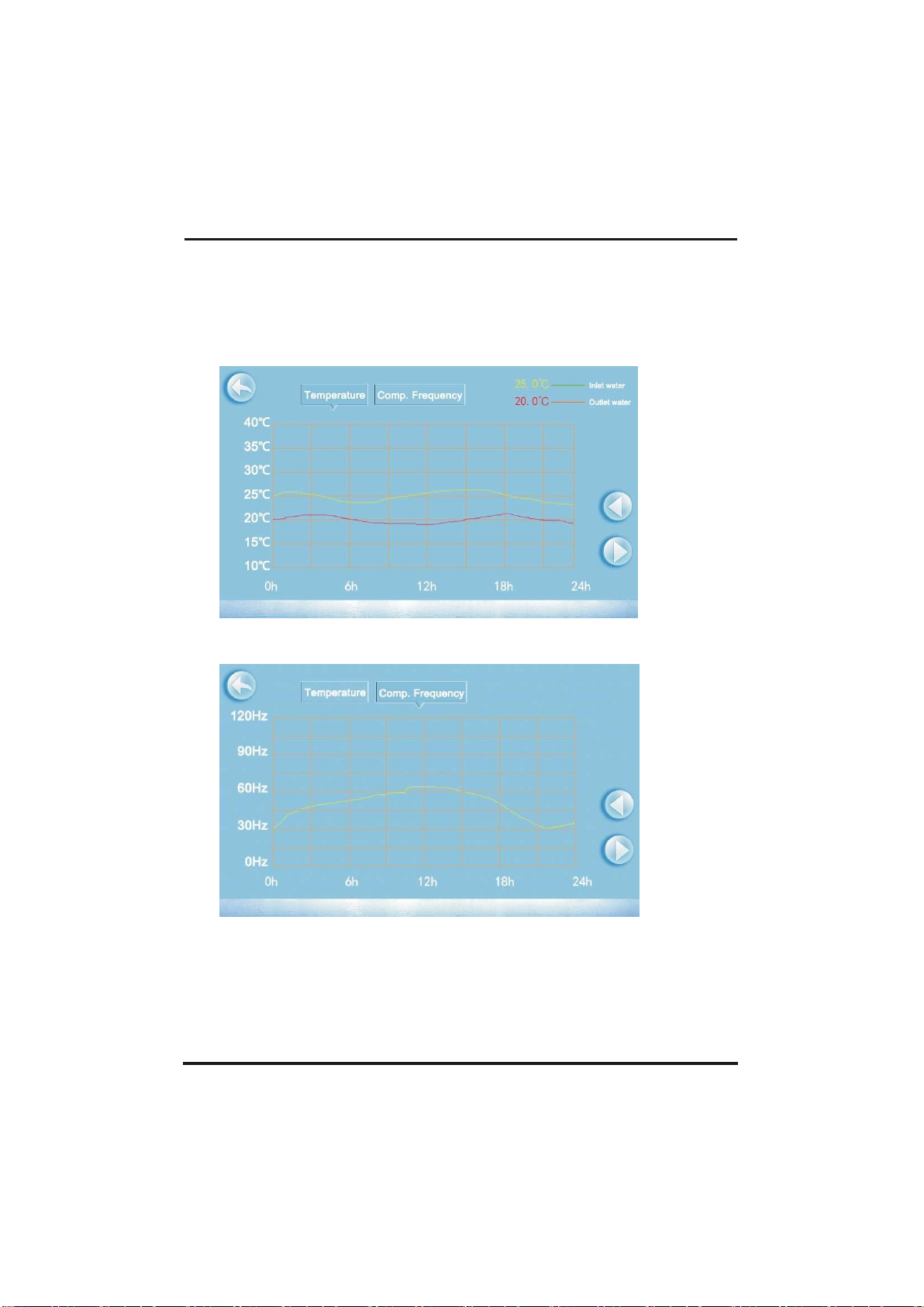
In the main interface, click the curve display button,
interface displays as follows:
2.7.1
Temperature recording curve is as follows:
2.7.2
Comp.Frequency curve
Temperature curve automatically updates every one hour, and
the curve record can be stored for 60 days;
Start from the latest curve saved time, if power is off and
curve data collecting time is less than one hour, the data in
this period will not be saved;
Page 24
21
4.OPERATION AND USE
4.3
Parameter list and breakdown table
(1) Electronic control fault table
Can be judged according to the remote controller failure code and
troubleshooting
Protect/fault
Fault
display
Reason
Elimination methods
Standby
Non
Normal boot
Non
Inlet Temp. Sensor Fault
P01
The temp. Sensor is broken
or short circuit
Check or change the temp. Sensor
Outlet Temp. Sensor Fault
P02
The temp. Sensor is broken
or short circuit
Check or change the temp. Sensor
Amibent Temp. Sensor Fault
P04
The temp. Sensor is broken
or short circuit
Check or change the temp. Sensor
Coil Temp. Sensor Fault
P05
The temp. Sensor is broken
or short circuit
Check or change the temp. Sensor
Suction Temp. Sensor Fault
P07
The temp. Sensor is broken
or short circuit
Check or change the temp. Sensor
Discharge Temp. Sensor
Fault
P081
The temp. Sensor is broken
or short circuit
Check or change the temp. Sensor
High Pressure Prot.
E01
The high-preesure switch is
broken
Check the pressure switch and cold circuit
Low Pressure Prot.
E02
Low pressure1 protection
Check the pressure switch and cold circuit
Flow Switch Prot.
E03
No water/little water in
water system
Check the pipe water flow and water pump
Anti-freezing Prot
E07
Water flow is not enough
Checkth ep ipew aterfl owa ndw hether
waters ystemi sja mmedo rn ot
Primary Anti-freezing Prot.
E19
The ambient temp. Is low
Secondary Anti-freezing Prot.
E29
The ambient temp. Is low
Inlet and outlet temp. too big
E06
Water flow is not enough
and low differential pressure
Check the pipe water flow and whether
water system is jammed or not
Low temperature protection
Non
The environment temp. is low
Comp. Overcurrent Prot.
E051
The compressor is overload
Check whether the system of the compressor
running normally
Exhaust Air over Temp Prot.
P082
The compressor is overload
Check whether the system of the compressor
running normally
Communication Fault
E08
Communicat ion failure between
wire controller and mainboard
Check the wire connection between
remote wire controller and main board
Antifreeze Temp. Sensor Fault
P09
antifreeze temp sensor is
broken or short circuited
check and replace this temp sensor
Waterway Anti-freezing Prot.
E05
water temp.or ambient temp. is
too low
EC fan feedback Fault
F051
There is something wrong with fan
motor and fan motor stops running
Check whether fan motor is broken or locked or
not
Pressure sensor Fault
PP
The pressure Sensor is broken
Check or change the pressure Sensor or
pressure
Fan Motor1 Fault
F031
1. Motor is in locked-rotor state
2.The wire connection between
DC-fan motor module and fan
motor is in bad contact
1.
Change a new fan motor
2.
Check the wire connection and make sure
they are in good contact
Page 25
22
4.OPERATION AND USE
Fan Motor2 Fault
F032
1. Motor is in locked-rotor state
2.The wire connection between
DC-fan motor module and fan
motor is in bad contact
1.
Change a new fan motor
2.
Check the wire connection and make sure
they are in good contact
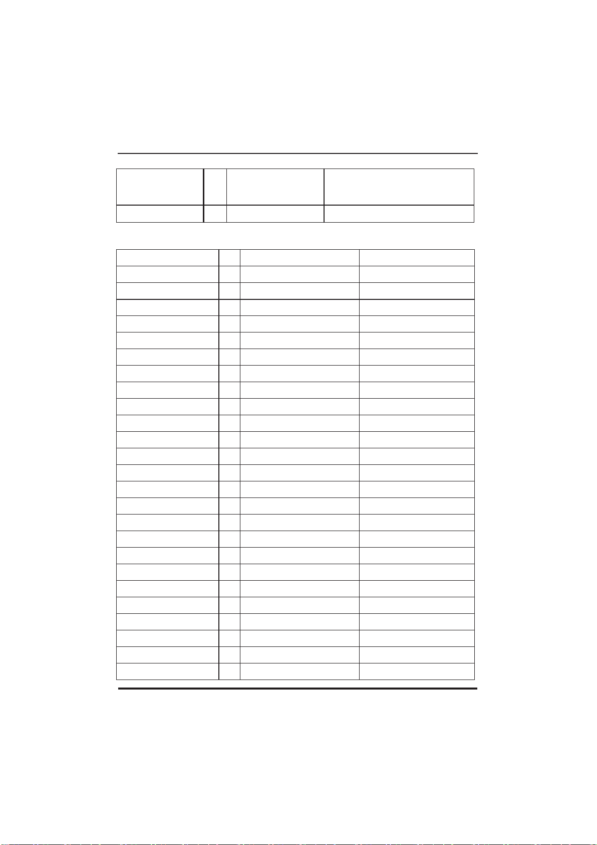
Communication Fault
(speed control module)
E081
Speed control module and main
board communication fail
Checkthe communication connection
Frequency conversion board fault table:
Protection/fault
Fault
display
Reason
Elimination methods
Drv1 MOP alarm
F01
MOP drive alarm
Recoveryafter the 150s
Inverter offline
F02
Frequency conversion board and main
board communication failure
Checkthe communicationconnection
IPM protection
F03
IPM modular protection
Recoveryafter the 150s
Comp. Driver Failure
F04
Lack of phase, step or drive hardware
damag
Checkthe measuringvoltage check
requencyconversion board hardware
DC Fan Fault
F05
Motor current feedback open circuit or
short circuit
Checkwhether currentreturn wires
connectedmotor
IPM Overcurrent
F06
IPM Input current is large
Checkand adjustthe current
measurement
Inv. DC Overvoltage
F07
DC bus voltage>Dc bus over-voltage
protection value
Checkthe input voltagemeasurement
Inv. DC Lessvoltage
F08
DC bus voltage<Dc bus over-voltage
protection value
Checkthe input voltagemeasurement
Inv. Input Lessvolt.
F09
The input voltage is low, causing the
inputcurrent is high
Checkthe input voltagemeasurement
Inv. Input Overvolt.
F10
The input voltage is too high, more than
outage protection current RMS
Checkthe input voltagemeasurement
Inv. Sampling Volt.
F11
The input voltage sampling fault
Checkand adjustthe current
measurement
Comm. Err DSP-PFC
F12
DSP and PFC connect fault
Checkthe communicationconnection
Input Over Cur.
F26
The equipment load is too large
PFC fault
F27
The PFC circuit protection
Check the PFC switch tube short circuit or
not
IPM Over heating
F15
The IPM module is overheat
Checkand adjustthe current
measurement
Weak Magnetic Warn
F16
Compressor magnetic force is not
enough
Inv. Input Out Phase
F17
The input voltage lost phase
Checkand measurethe voltage
adjustment
IPM Sampling Cur.
F18
IPM sampling electricity is fault
Checkand adjustthe current
measurement
Inv. Temp. Probe Fail
F19
Sensor is short circuit or open circuit
Inspectand replacethe sensor
Inverter Overheating
F20
The transducer is overheat
Checkand adjustthe current
measurement
Inv. Overheating Warn
F22
T
ransducer temperature is too high
Checkand adjustthe current
measurement
Comp. OverCur. Warn
F23
Compressor electricity is large
The compressorover-current
protection
Input Over Cur. Warn
F24
Input current is too large
Checkand adjustthe current
measurement
EEPROM Error Warn
F25
MCU error
Checkwhether the chip is damaged
Replacethe chip
V15V over/undervoltage fault
F28
The V15V is overload or undervoltage
Check the V15V input voltage in range
13.5v~16.5v or not
Page 26
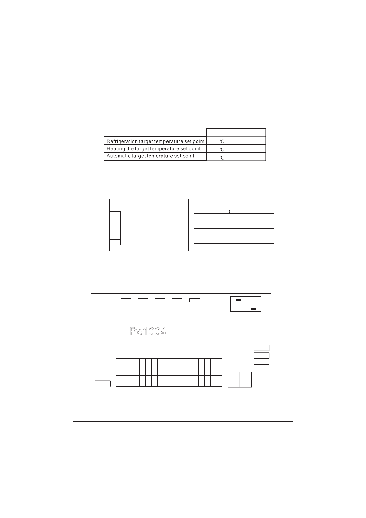
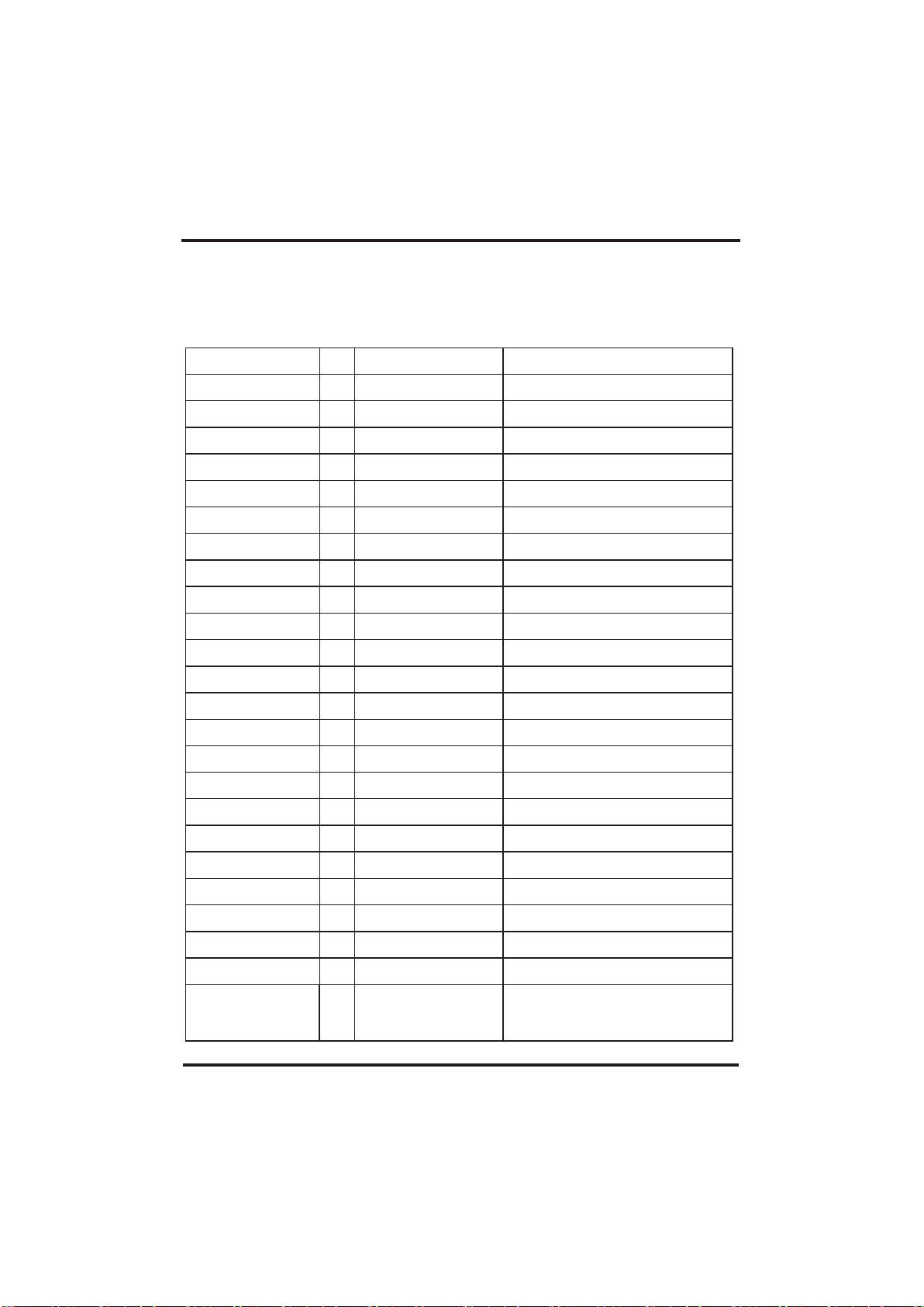
Default
27
27
27
Remarks
Adjustable
Adjustable
Adjustable
AC-N OUT5 OUT4 OUT3 OUT2
Pc1004
FUSE
CN9
12V
485_A2
485_B2
GND
12V
485_A1
485_B1
GND
AC-L OUT1
V
R
T
A
B
G
Sign
Meaning
V 12V power +
R
No use
T
No use
A
485A
B
485B
G
GND(power-)
4.OPERATION AND USE
(2) Parameter list
Meaning
4.4
Interface drawin
(1) Wire control interface diagram and definition
(2) Controller interface diagram and definition
+12V
+5V
PWM-OUT
PWM-IN
AI12(50K)
AI/DI11
AI/DI10
AI/DI09
AI/DI08
AI/DI07
AI/DI06
AI/DI05
AI/DI04
AI/DI03
AI/DI02
AI/DI01
GND
GND
GND
GND
GND
GND
GND
GND
GND
GND
GND
GND
GND
GND
GND
GND
GND
GND
23
T5AL250V
12V
485_A3
485_B3
GND
Page 27
4.OPERATION AND USE
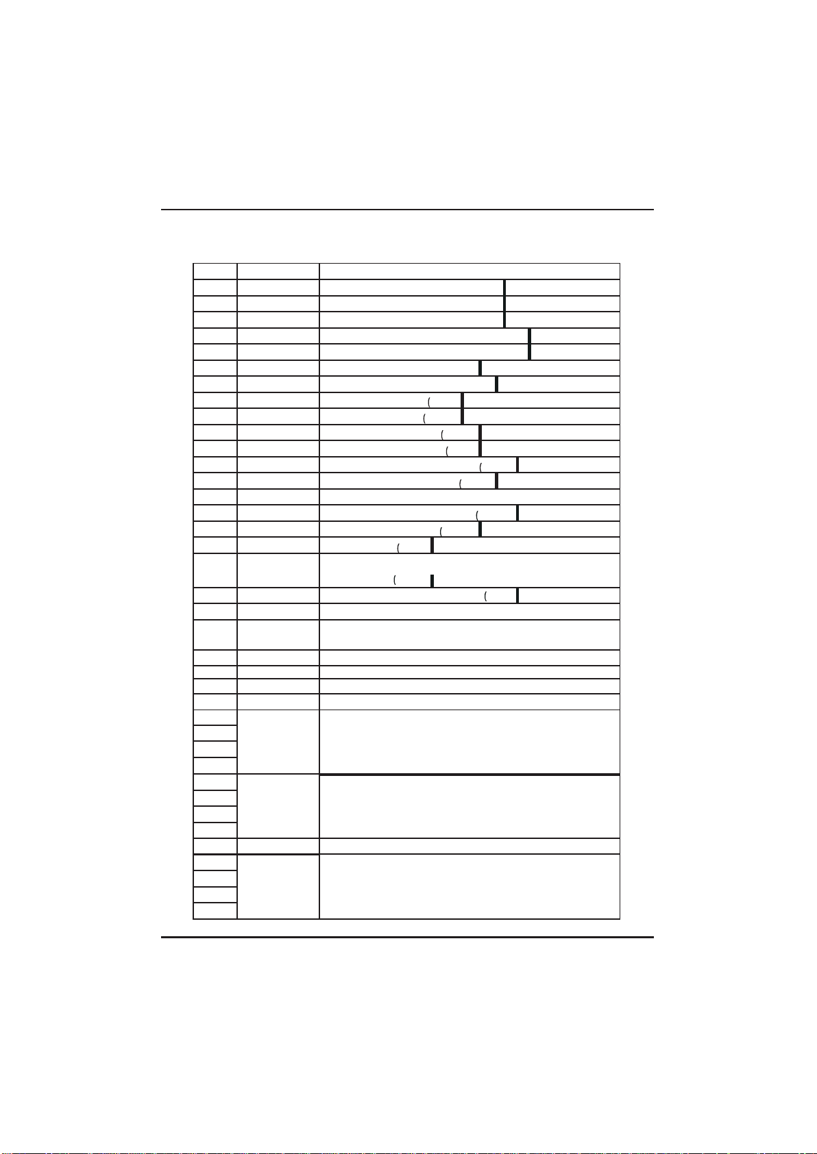
Main board of the input and output interface instructions below
Number Sign
Meaning
01
OUT1
Compressor ( output 220 -230VAC
02
OUT2
Water pump ( output 220-230VAC
03
OUT3
4-way valve ( output 220-230VAC
04
OUT4
High speed of fan ( output 220-230VAC
05
OUT5
Low speed of fan (output 220-230VAC
06
AC-L
Live wire ( input 220-230VAC
07
AC-N
Neutral wire ( input 220-230VAC
08
AI/DI01
Emergency switch input
09
AI/DI02
Water flow switch input
10
AI/DI03
System low pressure input
11
AI/DI04
System high pressure input
12
AI/DI05
System suction temperature input
13
AI/DI06
Water input temperature input
14
AI/DI07
Water output temperature ( input )
15
AI/DI08
System fan coil temperature input
16
AI/DI09
Ambient temperature input
17
AI/DI10
Mode switch input
18
AI/DI11
Master-slave machine switch / Antifreeze
temperature input
19
AI12(50K)
System Exhaust temperature input
20
0_5V_IN
Compressor current detection/Pressure sensor(input)
21
PWM_IN
Master-slave machine switch / Feedback signal of EC
fan ( input )
22
PWM_OUT
AC fan control ( output )
23 0_10V_OUT
EC fan control ( output )
24
+5V
+5V ( output )
25
+12V
+12V ( output )
26
GND
485_B1
485_A1
12V
Frequency conversion board communications
27 28 29 30
GND
485_B2
485_A2
12V
Color line controller communication
31 32
33
34
CN9
Electronic expansion valve
35
GND
485_B3
485_A3
12V
The port for centralized control system
36 37 38
24
Page 28
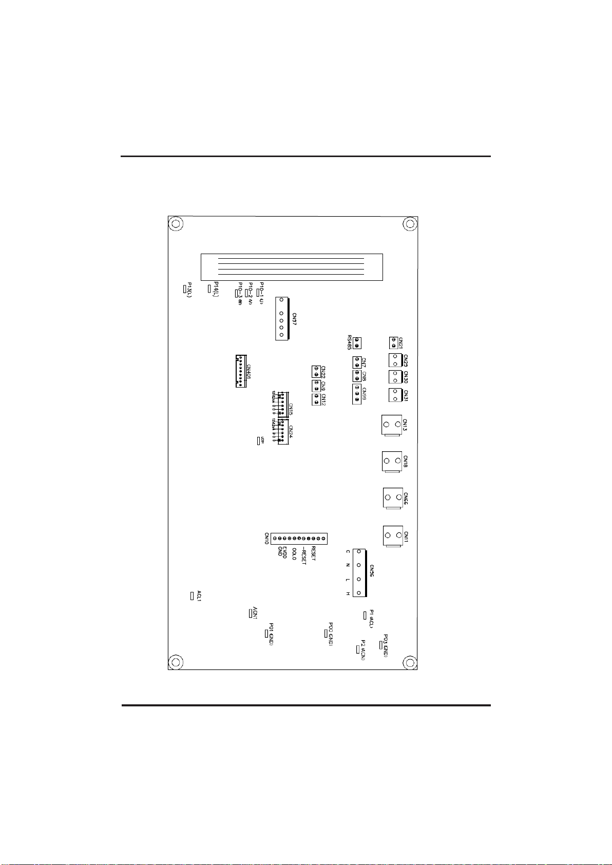
25
4.OPERATION AND USE
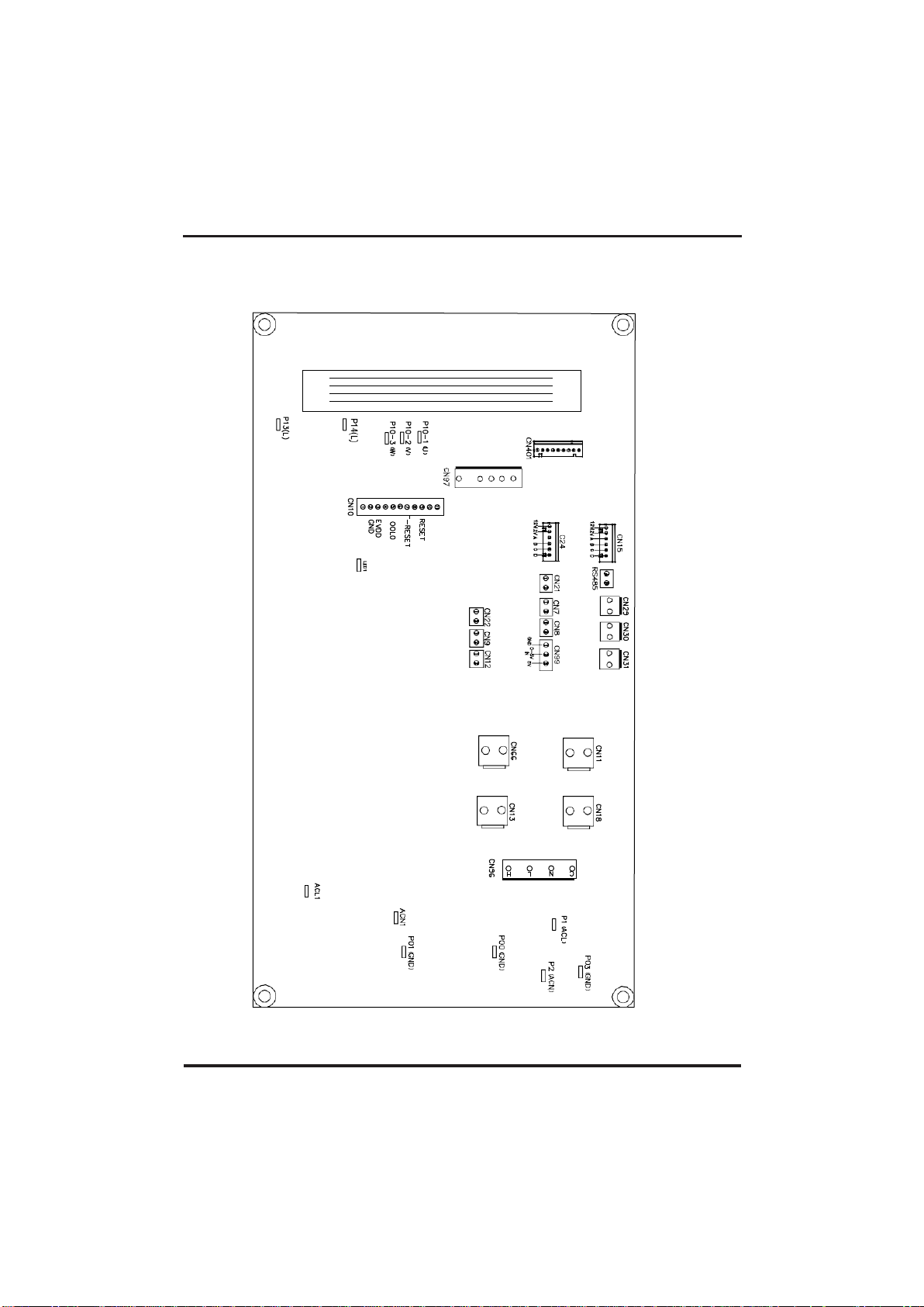
Controller interface diagram and definition
Page 29
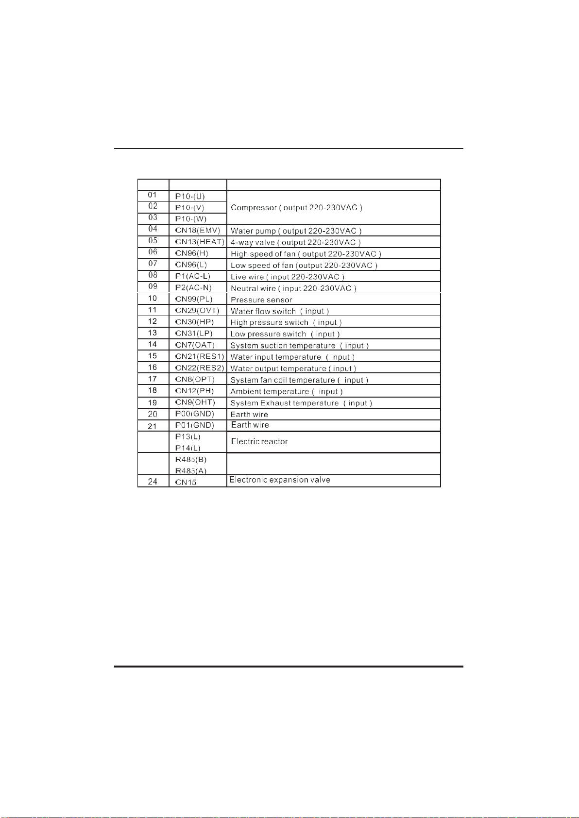
26
4.OPERATION AND USE
Controller interface diagram and definition
Page 30
27
4.OPERATION AND USE
Main board of the input and output interface instructions below
Number Sign
Meaning
22
23
Color line controller communication
Page 31

28
5. MAINTENANCE AND INSPECTION
Check the water s upply devic e and the release often. You should av oi d the condition of no
water or air entering into sy stem, as this will i nfluence unit's perf or manc e and reliabil it y.
You should clear the pool/ spa fi lter regularl y to av oid damage to the un it as a result of the
dirty of c logged f ilter.
The area around the unit should be dry, c lean and well v entil ated. C lea n the side heating
exc hanger regularly to maintain good heat exc hange as c ons erve ene rgy .
The operation press ure of the refrigerant s ys tem should only be serv ic ed by a certified
technici an .
Check the power supply and cable connection often,. Should the uni t b egin to operate
abnormally, s witch it off and c ontact the qualified tec hni cian.
Dis charge all water i n the water pump and water sy stem ,s o that f reez i ng of the water i n the
pump or w ater sy stem does not occ ur. You s hould dis charge the water at the bottom of
water pump i f the unit will not be us ed for an extended period of t ime. You s houl d chec k the
unit thoroughly and fi ll the s ystem with water fully before us ing it for th e f irst t ime after a
prolonged period of no usage.
Check s to the area
Prior to beginning work on sy stems containing fl am mabl e refrigerants, safety c hecks are
neces sary to ens ure that the risk of ignition is mini mised. For repai r to t he refrigerating sy
stem, the foll owing pr ec auti ons shall be complied with prior to c ondu c ting work on the sy
stem.
Work procedure
Work s hal l be undertak en under a c ontrol led proc edur e s o as to minim i se the ris k of a
flammable gas or v apour being present while the work i s being perform ed.
General w or k area
All maintenanc e s taff and others working in the loc al area s hal l be ins tr uc ted on the nature
of w or k being c arried out. Work in confi ned s pac es shall be avoided. T he area around the
work space shall be sec ti oned off. Ens ure that the conditions within the area hav ebeen made
safe by c ontrol of flamm abl e material.
Check ing for presenc e of refri gerant
The area s hall be c heck ed wi th an appropriate refri ger ant detec tor prio r to and during work, to
ens ur e the technic ian is aware of potential ly f lammable atmos phere s . Ensure that the
leak detection equipment bei ng us ed is suitable for use with fl am mabl e refrigerants, i. e.
non-spark ing, adequately s ealed or intrins icall y safe.
Presence of f ire extinguis her
I f any hot w or k is to be c onduc ted on the refri ger ation equipment or an y ass oc iated parts,
appropriate f ire extinguishi ng equipment s hal l be av ai lable to hand. Ha v e a dry powder or
CO 2 fir e ex tinguis her adjac ent to the charging area.
Page 32

29
5. MAINTENANCE AND INSPECTION
No ignition sources
No person carry ing out work in relation to a refr igeration sy stem whic h inv olves ex posing any
pipe work that contains or has contained f lammable refrigerant s hal l use any sourc es of i gni
tion in suc h a manner that it may l ead to the risk of f ire or ex plosion. All poss ible
ignition sources , inc luding cigarette s moking, s hould be kept suffic iently far aw ay from the si
te of i ns tal lati on, repairing, r emoving and dis posal, duri ng whi ch fl am mabl e refrigerant can
poss ibly be released to the s urrounding s pace. Prior to work taking place, the area
around the equipment is to be s ur veyed to mak e s ure that there ar e no fl ammable haz ards
or ignition r isk s. ᱑No Smok ing᱒ s igns s hal l be dis played.
Ventilated area
Ensure that the area i s in the open or that it is adequately venti lated befor e breaki ng into the
s ys tem or conducting any hot work . A degr ee of v enti lati on s hal l conti nue during the
period that the work is carried out. The ventilation s hould s afel y dispers e any rel eas ed
refrigerant and pr eferably ex pel it ex ternally into the atmosphere.
Check s to the refri ger ation equipment
Where el ectrical c omponents are being c hanged, they s hall be f it for the purpose and to the corr
ec t s pecific ation. At all t imes the manufac turer's m ai ntenance and s ervi ce gui del ines shall
be followed. I f i n doubt c onsult the manufac turer's tec hni cal depar tment for
ass istance.
The fol lowing check s s hal l be applied to ins tal lati ons us ing fl am mabl e refrigerants:
The charge si ze is in acc ordanc e with the room s ize wi thin whic h the refr igerant containing
parts are i nstalled;
The ventilation machinery and outlets are operati ng adequately and are not obstructed;
I f an indirec t refrigerati ng c ircui t is bei ng used, the sec ondary circ uit s hall be c hecked for
the pres enc e of refr igerant;
Mark ing to the equipment c ontinues to be v isi bl e and legible. M ar kings and signs that are
ill egi ble s hall be c orrected;
Refrigeration pi pe or components are installed in a posi ti on where they ar e unlik ely to be
expos ed to any s ubstance whic h may c orrode r efrigerant contai ni ng c omponents, unless
the c omponents are construc ted of materials w hi ch are i nherently res istant to bei ng
corr oded or are s uitabl y protec ted against bei ng s o c orroded.
Check s to el ec t rical devi ces
Repair and m ai ntenance to elec tr ical c om ponents shall i nc lude initial safety c heck s and
component i ns pection procedures. If a fault ex ists that c oul d c ompromise s afety, then no
electric al supply s hall be c onnec ted to the circ uit until it is s atis fac tor ily dealt with. I f the
faul t c annot be c or rected i mmediately but it is neces sary to conti nue operati on, an
adequate temporary s olution s hall be us ed. This shall be reported to the owner of the
equipment s o all parties are advis ed.
Initi al safety c hecks shall inc lude:
. T hat capaci tors ar e dis charged: this s hal l be done in a s afe manner to avoid poss ibility of
spark ing;
. T hat there no liv e elec tri cal components and w iring are ex pos ed w hile charging,
recov ering or purging the s ystem;
. T hat there is conti nui ty of earth bonding.
Page 33

30
5. MAINTENANCE AND INSPECTION
Repairs to sealed components
1)
During repairs to s ealed c omponents , all elec tri cal supplies shall be di sc onnec ted f rom
the equipment being work ed upon pr ior to any removal of sealed covers , etc. If it
is abs olutel y necess ary to hav e an electric al supply to equi pm ent during s ervi cing, then a
permanently operating form of leak detec ti on s hal l be loc ated at the m os t c rit ical point to
warn of a potentially haz ardous situation.
2)
Par tic ular attenti on s hal l be paid to the foll ow ing to ensure that by worki ng on electric al
components, the casi ng is not altered i n s uch a w ay that the level of pr otection is affec ted.
This shall inc lude damage to c abl es , ex cess iv e number of c onnec tions , terminals not made
to ori gi nal s pecific ation, damage to s eals, incorrec t f it ti ng of gl ands , etc.
Ensure that apparatus is m ounted securely.
Ensure that seals or s eal ing materials hav e not degr aded suc h that they no longer s erve
the purpose of prev enting the ingres s of f lammable atm os pheres. R epl acement parts s hal l
be in ac cordance with the manufac tur er 's speci fi cations.
NOTE: T he us e of sili con sealant may inhibit the effectiveness of some types of leak detec
ti on equipment. Intri nsic ally s afe components do not hav e to be is olated prior to work ing
on them .
Repair to i ntrins ical ly safe components
Do not apply any permanent i nduc ti ve or c apacitance loads to the c irc uit wi thout ens uring
that t hi s wil l not exc eed the permi ssi ble v olt age and current permi tted for the equipment i n
use.
Intri ns ic al ly s afe components ar e the onl y ty pes that can be w or ked on whil e l ive in the
presenc e of a f lammable atm os phere. The tes t apparatus shall be at the c orrect rating.
Replac e c omponent s only w ith parts spec ifi ed by the manufacturer. Other parts may resul t
in
the
ignition of refrigerant i n the atmosphere f rom a leak .
Cabling
Check that cabling will not be s ubject to wear, corr os ion, ex cess iv e pres sure, v ibration,
sharp edges or any other advers e envi ronmental effect s . The check shall als o take into
acc ount the effec ts of aging or c ontinual vi bration f rom sources s uch as compres sors or
fans .
Detection of f lammable refri gerants
Under no c irc um stanc es shall potenti al sources of ignition be used in the searc hing for or
detec ti on of refri gerant leaks . A halide torc h (or any other detector using a nak ed f lame)
shall not be us ed.
Leak detec ti on methods
The fol lowing leak detec ti on methods are deemed acceptable for s ys tems c ontaini ng
f lammable refri ger ant s.
Electronic l eak detectors s hal l be us ed to detect fl ammable r efrigerants, but the s ens it ivi ty
may not be adequate, or may need re-cali bration. (Detec t ion equipment s hall be calibrated in a
refri gerant-free area.) Ens ure that the detector is not a potential s our ce of ignition and is s uitabl
e for the refrigerant us ed. Leak detection equipment shall be set at a percentage of the LF L of
the refr igerant and s hall be c alibrated to the refrigerant employed and the
appropriate percentage of gas (25 % maxim um ) i s confirmed.
Leak detec ti on f luids are sui table for us e w ith mos t refrigerants but the use of detergents
containing chlorine shall be avoi ded as the c hlorine may react with the refri ger ant and corr
ode the c opper pipe-work .
I f a leak is s uspected, all nak ed f lames s hall be removed/ extinguis hed.
I f a leakage of refrigerant is found which requires brazing, all of
the refr igerant shall be
recov
ered f rom the s ystem, or i solated (by means of shut off v alves ) in a part of the s ystem remote f
rom the leak . Oxy gen f ree ni trogen (OF N) shall then be purged through the sys tem both befor
e and during the brazing process .
Page 34

31
5. MAINTENANCE AND INSPECTION
Remov al and evac uation
When break ing i nto the refrigerant c irc ui t to m ak e repai rs or for any other purpos e
conv entional procedures s hall be us ed. Howev er, it is important that bes t prac ti ce is
followed sinc e f lammabil ity is a consi deration. T he follow ing proc edure s hal l be adhered to:
. R emove refri ger ant;
. Purge the ci rcuit with inert gas;
. Ev acuate;
. Purge agai n w ith inert gas;
. Open the cir cuit by cutti ng or brazi ng.
The refrigerant charge shall be recov ered i nto the corr ec t rec overy c yli nders . T he s ystem
shall be "f lus hed" wi th OFN to r ender the unit safe. This pr oc ess m ay need to be repeated
sev eral ti mes. C ompressed air or oxy gen s hal l not be us ed for this tas k.
Fl us hing shall be ac hieved by breaki ng the v acuum in the sy stem with OFN and continuing to f
ill until the w or king press ur e is achiev ed, then venting to atm os phere, and f inall y pulling
down to a vacuum. This proc ess s hal l be repeated until no r efrigerant is within the s ystem.
When the fi nal OFN c harge is used, the sys tem s hall be v ented down to atmos pher ic
press ure to enabl e work to take place. T his operati on is abs olutel y vi tal if brazing
operati ons on the pipe-w ork are to tak e pl ace.
Ensure that the outl et for the vacuum pump is not c lose to any i gni tion sourc es and there is
ventilation available. worki ng on them.
Labelling
Equipment shall be labelled stating that i t has been de-c ommissioned and emptied of
refrigerant. The label s hall be dated and si gned. Ens ure that there ar e labels on the
equipment s tating the equipment contains f lammable refr igerant .
Rec overy
When r em ov ing refri ger ant fr om a sy stem, ei ther for s ervi cing or dec ommis sioning, i t is
recomm ended good practic e that al l refri gerants are removed saf ely.
When t ransferring refrigerant into cy linders, ens ure that only appropri ate refr igerant recov
ery cy linders are employed. Ens ure that the correc t number of cy linders for hol ding the total
s ys tem c harge is av ailable. All c ylinders to be us ed are designated for the
recov ered refrigerant and labelled for that refrigerant (i .e. special c yl ind er s for the r ec overy of
refrigerant). Cy linders s hall be c omplete wi th press ure r el ief valve and as soci ated shut- off
valv es in good work ing order. Empty rec overy c yli nders are ev acuated and, if possi ble, cooled
before rec ov ery occ urs.
The recov ery equipment shall be in good w or king order w ith a set of ins truc ti ons
conc erning the equipment that is at hand and s hal l be s uitable for the recov ery of
f lammable refri ger ants. In addition, a set of c al ibrated weighing sc ales shall be avail able
and i n good worki ng order. Hos es shall be complete with l eak -free dis connect couplings
and i n good condition. Befor e us ing the recovery machine, c heck that it is in s atis fac tor y
work ing order, has been proper ly maintained and that any associated elec tri cal
components are s ealed to prevent i gni ti on in the ev ent of a refr igerant release. Consult
manufac turer if in doubt .
The recov ered refrigerant s hall be r eturned to the refrigerant s uppl ier in the correc t
recov ery cy linder, and the relevant Was te Transfer Note arranged. Do not mi x refrigerants in
recov ery units and es pec ially not in cy linders.
I f c om pr es sors or c ompress or oil s are to be removed, ensure that they hav e been
evac uated to an ac ceptable level to mak e c ertai n that f lammable refrigerant does not
remain within the lubric ant. The ev acuation proc ess s hall be c arried out prior to returning the
c ompressor to the suppliers . Only elec tr ic heati ng to the compress or body shall be
employed to ac celerate this pr oc ess . When oi l is drained from a sy st em, i t shall be carr ied
out s afely.
Page 35

32
5. MAINTENANCE AND INSPECTION
Dec om miss ioning
Before carr ying out this procedure, it is essential that the technic ian i s completely famili ar with
the equipment and all its detail . I t is recommended good practice that all refrigerants are
recovered safely. Pri or to the tas k being carried out, an oi l and refrigerant s ample s hall be tak
en in cas e analy sis is required prior to re-us e of reclaim ed refrigerant. I t is es sential that
electric al pow er i s avail abl e before the tas k is c ommenced.
a) Bec ome famil iar with the equi pment and i ts operation.
b) Is olate s ys tem electric ally.
c) Before attem pting the procedure ensure that:
. M ec hanical handling equi pment is av ailable, i f required, for handl ing refrigerant cyl inders;
. All personal protec t ive equipment is av ailable and being used correc tl y;
. T he rec overy proc es s is supervis ed at all t imes by a competent person;
. R ecovery equipment and c ylinders conform to the appropr iate standards.
d) Pum p down refrigerant sy stem, i f poss ible.
e) If a vacuum is not pos si bl e, make a manifold s o that r efrigerant can be remov ed f rom
vari ous par ts of the sy stem.
f) ) Make sure that cy linder is si tuated on the s cales before r ec overy takes pl ace.
g) Start the recov ery machine and operate in ac cordance with manufac turer's i nstructions.
h) Do not overfill c yli nders . (N o more than 80 % v olume l iquid charge).
i) Do not ex ceed the maximum work ing press ur e of the cy linder, even temporari ly.
j)
When the cy linders have been f il led c orrectly and the proces s completed, mak e s ure that
the c yli nders and the equipment are remov ed f rom site promptly and all is olation v alves on
the equipment are cl osed off.
k)
R ec overed refr igerant shall not be c har ged into another r efrigeration sy stem unles s it
has been c leaned and check ed.
Charging procedures
In addition to conv entional c hargi ng procedures , the followi ng requirements shall be
followed.
Ensure that contaminati on of different refrigerants does not occ ur w hen usi ng c har gi ng
equipment. Hoses or li nes shall be as short as possi ble to minimi se the amount of
refrigerant c ontained in them.
Cy linders s hall be k ept upright.
Ensure that the refrigeration s ys tem is ear thed prior to charging the s ys tem with
refrigerant.
Label the sy stem when c harging is compl ete (if not already).
Extreme care shall be taken not to ov er fil l the refrigerati on s ystem.
Prior to rec har gi ng the s ys tem it shall be press ure tested with OFN . The sy stem shall be
leak tested on compl etion of c harging but pr ior to commi ss ioning. A foll ow up leak test shall
be carried out prior to l eav ing the si te.
The safety wire model is 5* 20_5A/ 250VAC ,And must meet the ex pl osion-proof
requirements
Page 36
33
6.APPENDIX
6.1 Cable specification
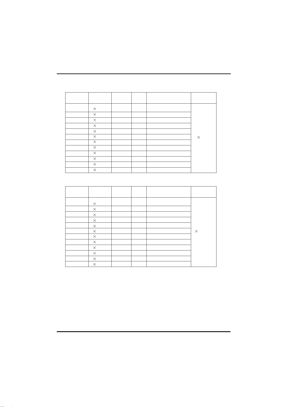
(1) Single phase unit
Nameplate
maximum
current
Phase line
Earth line
MCB
Creepage protector
Signal line
No more
than 10A
2 1.5mm
2
1.5mm
2
20A
30mA less than 0.1 sec
n
0.5mm2
10~16A
2
2.5mm
2
2.5mm
2
32A
30mA less than 0.1 sec
16
~25A
2
4mm
2
4mm
2
40A
30mA less than 0.1 sec
25
~32A
2
6mm
2
6mm
2
40A
30mA less than 0.1 sec
32
~40A
2
10mm
2
10mm
2
63A
30mA less than 0.1 sec
40
~63A
2
16mm
2
16mm
2
80A
30mA less than 0.1 sec
63~75A
2
25mm
2
25
mm
2
100A
30mA less than 0.1 sec
75~101A
2
25mm
2
25
mm
2
125A
30mA less than 0.1 sec
101~123A
2
35mm
2
35mm
2
160A
30mA less than 0.1 sec
123~148A
2
50mm
2
50mm
2
225A
30mA less than 0.1 sec
148~186A
2
70mm
2
70mm
2
250A
30mA less than 0.1 sec
186~224A
2
95mm
2
95mm
2
280A
30mA less than 0.1 sec
(2) Three phase unit
Nameplate
maximum
current
Phase line
Earth line
MCB
Creepage protector
Signal line
No more
than 10A
3
1.5mm
2
1.5mm
2
20A
30mA less than 0.1 sec
n
0.5mm2
10~16A
3
2.5mm
2
2.5mm
2
32A 30mA less than 0.1 sec
16
~25A
3
4mm
2
4mm
2
40A
30mA less than 0.1 sec
25
~32A
3
6mm
2
6mm
2
40A
30mA less than 0.1 sec
32
~40A
3
10mm
2
10mm
2
63A
30mA less than 0.1 sec
40
~63A
3
16mm
2
16mm
2
80A
30mA less than 0.1 sec
63~75A
3
25mm
2
25
mm
2
100A
30mA less than 0.1 sec
75~101A
3
25mm
2
25
mm
2
125A
30mA less than 0.1 sec
101~123A
3
35mm
2
35mm
2
160A
30mA less than 0.1 sec
123~148A
3
50mm
2
50mm
2
225A
30mA less than 0.1 sec
148~186A
3
70mm
2
70mm
2
250A
30mA less than 0.1 sec
186~224A
3
95mm
2
95mm
2
280A
30mA less than 0.1 sec
When the unit will be installed at outdoor, please use the cable which can against UV.
Page 37
34
6.APPENDIX
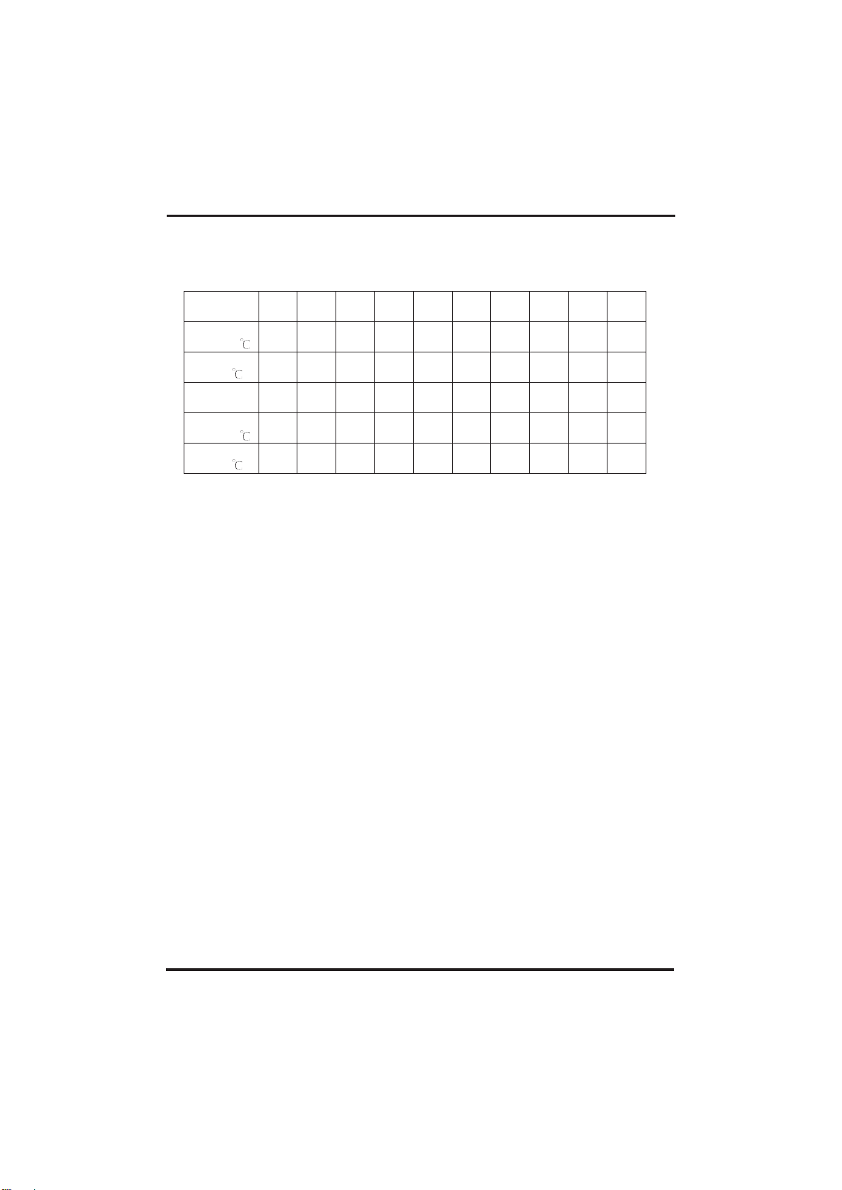
6.2 Comparison table of refrigerant saturation temperature
Pressure
(MPa )
0 0.3 0.5 0.8 1 1.3 1.5 1.8 2 2.3
Temperature
(R410A)( )
-51.3
-20 -9 4 11 19 24 31
35 39
Temperature
(R32)( )
-52.5
-20 -9 3.5 10 18 23
29.5 33.3 38.7
Pressure
(MPa )
2.5 2.8 3 3.3 3.5 3.8 4 4.5 5 5.5
Temperature
(R410A)( )
43 47 51
55
57 61 64 70 74 80
Temperature
(R32)( )
42 46.5 49.5 53.5 56 60 62
67.5 72.5 77.4
Page 38

Note:
Page 39

Page 40
Code:83900023
 Loading...