

Page 1
3
INSTALLATION AND OPERATING INSTRUCTIONS I INSTALLATION AND OPERATING INSTRUCTIONS
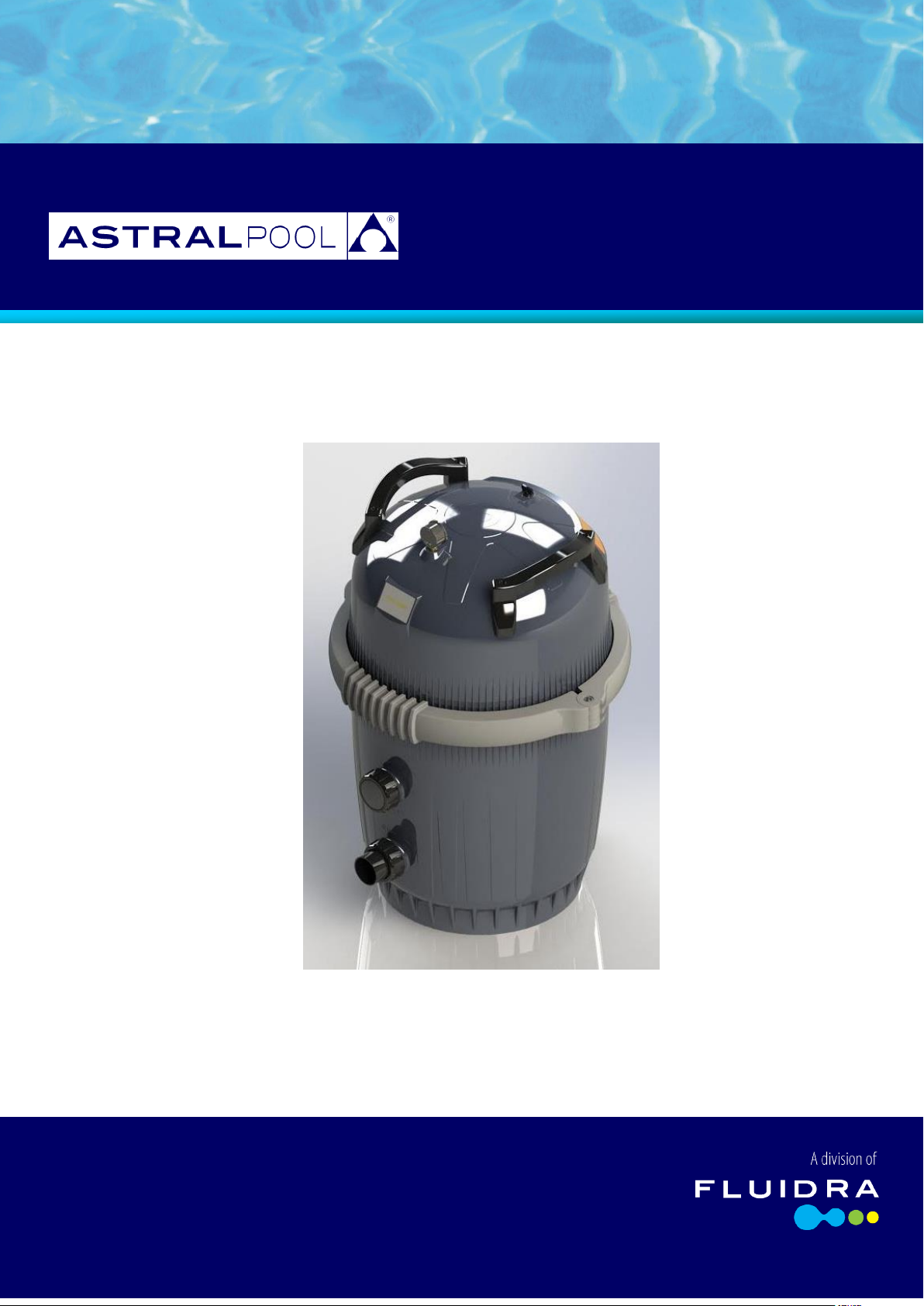
UF 80/100
ULTRA FINE
CARTRIDGE FILTER
INSTALLATION AND
OPERATING INSTRUCTIONS
Page 2
2
IMPORTANT SAFETY PRECAUTIONS
ATTENTION INSTALLER: This guide contains important information about the installation, operation and safe use of this
product. This information should be given to the owner and/or operator of this equipment after installation or left on or
near the filter.
ATTENTION USER: This manual contains important information that will help you in operating and maintaining this filter.
Please retain it for future reference.
WARNING- Before installing this product, read and follow all warning notices and instructions which are included.
Failure to follow safety warning and instructions can result in severe injury, death or property damage.
CONSUMER INFORMATION AND SAFETY
The Astralpool UF Series cartridge filter is designed and manufactured to provide many years of safe and reliable service
when installed, operated and maintained according to the information in this manual and the installation codes referred to in
later sections. Throughout the manual, safety warnings and cautions are identified by the symbol. Be sure to read and
comply with all of the warnings and cautions.
WARNING: Do not operate the filter until you have read and understand clearly all the operating instructions and
warning messages for all equipment that is a part of the pool circulating system. The following instructions are intended as a
guide for initially operating the filter in a general pool installation, however each installation may have unique conditions
where the starting procedure could be different. Failure to follow all operating instructions and warning messages can result
in severe injury, death or property damage.
WARNING: THIS FILTER OPERATES UNDER HIGH PRESSURE.
When any part of the circulating system, (filter, pump, valves, clamp etc) are serviced, air can enter the system and become
pressurized. Pressurized air can cause the lid to be blown off, which can result in severe injury, death, or property damage.
To avoid this potential hazard, please follow these instructions.
1. Before repositioning valve(s) and before beginning the assembly, disassembly or adjustment of the clamp of the filter
or any other service of the circulating system, TURN THE PUMP OFF and shut OFF any automatic controls to
ensure the system is NOT inadvertently started during the servicing, Open the AIR BLEED VALVE in the top of the
filter lid and wait until all pressure is relieved.
2. Whenever installing the filter clamp, follow the filter clamp installation instructions exactly.
3. Once service on the circulating system is complete, FOLLOW THE RESTART INSTRUCTIONS EXACTLY
4. Maintain circulation system properly. Replace worn or damage parts immediately
5. Be sure that the filter is properly mounted and positioned according to instructions provided.
WARNING: Due to the potential risk that can be involved, it is recommended that the pressure test be kept to
the minimum time required by the local code. Do not allow people to work around the system when the circulation system
is under pressure test. Establish a barrier and post warning signs around the pressurized equipment. If the equipment is
located in a plant room, lock the access doors and post warning signs.
Never attempt to adjust any closures or lids or attempt to remove or tighten bolts on the system when pressurized. These
actions can result in a separation or failure of the system components. This instantaneous release of pressure can cause
components to be accelerated to high velocities and to travel great distances. These components could cause severe
personal injury or death if they were to strike a person.
WARNING: Risk of electrical shock or electrocution.
This pool filter must be installed by a qualified pool serviceman in accordance with the National Electrical Code (NEC) and
all applicable local codes and ordinances.
Always disconnect power to the pool equipment at the circuit breaker before servicing any of the equipment. Ensure that
the disconnected circuit is locked out or properly tagged so that it cannot be switched on while you are working on the
pool equipment. Failure to do so could result in serious injury or death to service people, pool users or others due to
electric shock.
Position the filter and the air relief valve to safely direct water drainage and purged air or water. Water discharge from an
improperly positioned filter or valve can create an electrical hazard that can cause severe personal injury as well as damage
property.
; WARNING: To reduce the risk of injury, do not permit children to use this product unless they are closely
supervised at all times.
CAUTION: This filter is for use with permanently installed pools and may be used with hot tubs and spas if so
marked. Do not use with storable pools, A permanently installed pool is considered in or on the ground or in a building such
that it cannot be readily disassembled for storage. A storable pool is constructed so that it may be readily disassembled for storage and
reassembled to its original integrity.t
INST 412 UF ULTRA FINE Cartridge Filter V08-20
Page 3
3
GENERAL INSTALLATION INFORMATION.
The following information should be read carefully as it outlines the proper manner of care and operation of your filter
system. You can expect maximum efficiency and product life from you filtration system by following these instructions and
taking the necessary preventative maintenance.
*.Have a trainer pool professional perform all pressure testing
* Do not connect the system to a high pressure or city water systems.
* Trapped air in the system can create a hazardous condition. MAKE SURE to purge all air from the system before operating
or testing of the equipment.
* DO NOT PRESSURE TEST WITH COMPRESSED AIR
* Check local codes for restrictions on backwash to waste piping, separation tank requirements.
*Piping must conform to local/state plumbing and sanitary codes
*Support piping independently to prevent strains on the filter or valve
* Fittings restrict flow, for best efficiency, use the fewest possible fittings
* a check valve installed between the filter inlet will prevent contaminants from draining back into the Pool.
* A check valve installed between the filter and heater will prevent hot water from backing up into the filter and deforming
the internal components.
* All wiring, grounding and bonding of associated equipment must meet local and/or National Electrical Code (NEC)
standards
Record your Equipment details here for quick reference:
Model No.: ____________________________
Serial No.: ____________________________
Initial Pressure (p.s.i.): _______________________
INST 412 UF ULTRA FINE Cartridge Filter V08-20
Page 4

4
GENERAL OVERVIEW
The Astralpool UF Cartridge filter features 4 easily accessible and removable filter cartridges. When water passes through
these cartridges, microscopic impurities like dirt, algae and some forms of bacteria are filtered out, giving you water that
really sparkles.
The 4 cartridges design greatly increases the filter’s internal surface area, meaning a much greater cleaning capacity for every
cycle without the need for a larger filter. Cleaning couldn’t be easier, just simply removing the clamp band and lifting the lid
off. To access the 4 cartridges.
INSTALLATION
Only a Qualified service person should install the Astralpool UF Cartridge filter.
WARNING – Risk of electrical shock or electrocution.
Position the filter and allowing for the air/water bleed valve located in the lid to safely direct water drainage and purged air
or water. Water discharged from an improperly position filter can create an electrical hazard that can cause severe personal
injury as well as damage property.
WARNING – THIS FILTER OPERATES UNDER HIGH PRESSURE
Never subject the filter to pressure in excess of the maximum working pressure, even when conducting hydrostatic
pressure testing. Pressures above the maximum working psi pressures can cause the lid to be blown off. Which can result in
severe injury, death or property damage
1. The filter should be mounted on a level concrete slab. Position the filter so that the instructions, warning and
pressure gauge are visible to the operator. It should also be positioned so that the piping connections, control valve
and drain port are convenient and accessible for servicing and winterizing.
2. Install electrical controls (timers, Chlorinators, power points) at least 6 feet from the filter. This will allow you
enough room to stand clear of the filter during start up.
3. Allow sufficient clearance around the filter to allow visual inspection of the clamp is correctly installed around the
tank flanges. Using a soft mallet tap the clamp to ensure uniform loading during the clamp tightening.
4. Allow enough space above the filter to remove the filter lid for cleaning and servicing. This distance should be a
minimum of 2 feet
5. The Astralpool UF Cartridge filter has 1 inlet, 2 outlets and a drain port. Either inlet can be used (top inlet height
for other brands heaters, bottom inlet to suit HINRG 175,HiNRG 250 or HiNRG 400 heater. Whichever port you
use the other will have to be plugged with plug cap supplied with filter
6. Make all plumbing connections in accordance with local plumbing and building codes. Check local codes for
restrictions on backwash to waste piping, separation tank requirements. Allow minimum of 1 hour for glue to dry
on pipe fittings before pressuring up the system.
7. Filter plumbing connections are provided with an o-ring seal to avoid damage to the o-rings, use only a silicone base
lubricant on the o-rings. Do not use a petroleum based lubricate as it it degrade the o-rings.
8. Install the pressure gauge (supplied with the filter) into the marked hole in the lid, using Trflon tape on the gauge
thread.
9. If the filter is installed below water level, isolation valves must be installed on the inlet & outlet to enable the filter
to be dismantled for cleaning without the loss of water from the pool or spa.
10. It is recommended that a 3 way valve be installed on the return line to allow draining of water from the pool or spa
when necessary.
11. The maximum working pressure of this filter is 50 psi. Never subject this filter to pressure in excess of the amount,
even when conducting hydrostatic pressure testing. Pressures above 50 psi can cause the lid to be blown off, which
can result in severe injury, death or property damage
When performing hydrostatic pressure testing or when testing for external leaks of the completed filtration and plumbing
system, ensure that the maximum pressure that the filtration system will be subject to DOES NOT EXCEED THE
MAXIMUM WORKING PRESSURE OF ANY OF THE COMPONENTS CONTAINED WITHIN THE SYSTEM. In most
cases the maximum working pressure will be sated on each component of the system.
If doubt exists as to the pressure to which the system will be subjected, install an Automatic pressure relief or pressure
regulator in the circulation system for the lowest working pressure of any of the components in the system.
INST 412 UF ULTRA FINE Cartridge Filter V08-20
Page 5

5
GENERAL FILTER INFORMATION
Filter area (sq ft)
Weight of UF
No of 500ml Containers
80
2.75 kg (6 lbs)
16
100
4.5 kg (10Ibs)
20
WARNING: THIS FILTER OPERATES UNDER HIGH PRESSURE.
When any part of the circulating system, (filter, pump, valves, clamp etc) are serviced, air can enter the system and become
pressurized. Pressurized air can cause the lid to be blown off, which can result in severe injury, death, or property damage.
To avoid this potential hazard, please follow these instructions.
1. Before repositioning valve(s) and before beginning the assembly or disassembly or adjustment of the clamp or any
other service of the circulating system.
2. Turn the pump OFF and shut off any automatic controls to ensure the system is not inadvertently started during
the servicing.
3. Undo the bleed valve in the top of the lid slowly to relief air pressure from the filter until all pressure from the filter
is relieved.
4. Whenever installing the filter clamp FOLLOW THE FILTER CLAMP INSTALLATION INSTRUCTIONS EXACTLY.
5. Once the service on the circulating system is complete, FOLLOW THE RE-START PROCEDURE
INSTRUCTIONS.
6. Maintain circulation system properly. Replace worn or damaged parts immediately
7. Ensure that the filter is properly mounted and positioned according to instructions provided.
CLAMP INSTALLATION.
Please follow the following instructions exactly to prevent the lid from blowing off during system restart or later operation.
1. Perform the following steps before working on any part of the circulating system.
2. Turn the pump off and shut off any automatic controls to ensure that the system is not inadvertently started during
servicing
3. Open up the air bleed screw located in the lid to remove air pressure and leave open until all air pressure is
relieved.
4. Be certain the o-ring is in correct position in the lower tank half groove, fit the top filter lid carefully over the lower
half of the filter tank ensuring oring stays in position as doing so.
5. Holding the ends of the filter clamp apart, position the center segment of the filter clamp over both upper and
lower tank flanges. Bring the ends of the clamp together, while ensuring the T-BOLT located correctly in 1 ½ of the
clamp. While holding the 2 halves together screw on the brass nut until you are able to let go of the clamp and it
stays in position.
6. Begin to tighten the brass nut with a ¾”wrench, tighten the brass nut until the gap between the two clamps is
approx. 1 finger width. 5/8”(16mm)to 3/4”(19mm). DO NOT over tighten beyond this gap specified
PREPARING DIATOMITE FOR FILTER
Your filter requires diatomaceous earth (D.E . or diatomite) for proper filtration and operation. Your filter elements must
be pre-coated with this material in order to protect their surfaces and provide the most efficient filtering action. Refer to
the table below for proper quantity to use with your filter. We recommend the use of D.E. which is sold and labelled for use
with swimming pools and spas. These grades of D.E, typically have a median particle size of 34 microns, which is ideal for
most applications.
1. The Astralpool UF Cartridge filter listed below shows the appropriate amounts of diatomite to be used to pre-coat
the filter elements. Using an old 500ml container or something similar, fill level to the top with diatomite. This is
equal in weight of ½ lb of diatomaceous earth. DO NOT “PACK” or compress diatomite into the 500ml container.
2. Mix the required amount of diatomite with sufficient water in a bucket to make a thin, milky mixture.
3. Follow the instructions below for coating the filter elements to introduce the slurry of the diatomite into the filter.
INST 412 UF ULTRA FINE Cartridge Filter V08-20
Page 6

6
COATING OF THE FILTER ELEMENTS
CAUTION- The following information should be read very carefully as it outlines the proper manner of care and
operation of your filter. You can expect maximum efficiency and life from your filter by following these instructions and
taking the necessary preventative care.
1. Open the air bleed valve in the top of the filter lid
2. Prepare recommended amount of diatomaceous earth by mixing it with water in a bucket until it is the consistency
of milk ( see above PREPARING DIATOMITE)
3. On initial start-up, the pump must be primed by filling the hair lint basket with water. You may have to do this
serval times before the pump primes
4. Follow the steps outlined in START INSTRUCTIONS for system start up for PRIMING the filtration system.
5. With the filtration system now primed and operating correctly, add the Diatomite Slurry from the bucket directly
into the top of the skimmer. With the pump running and the pool skimmer valve open, pour the mixture directly
into the skimmer. The slurry will be drawn into the filter.
6. Your filter is now operational. Note down the original starting pressure on the pressure gauge on the filter and
record it below.
7. Clean your filter (BACKWASH) when pressure reads between 10 to 15 psi higher than the original starting
pressure. Your filter pressure reading will increase as it removes dirt from your pool. However, this build-up of
pressure will vary due to different bathing loads, temperature, weather conditions and so on.
ORIGINAL STARTING PRESSURE………………………psi
CLEAN FILTER WHEN GAUGE REACHES……………………..psi
STARTING INSTRUCTIONS
WARNING: THIS FILTER OPERATES UNDER HIGH PRESSURE.
When any part of the circulating system, (filter, pump, valves, clamp etc) are serviced, air can enter the system and become
pressurized. Pressurized air can cause the lid to be blown off, which can result in severe injury, death, or property damage.
To avoid this potential hazard, please follow these instructions.
1. Before start up, make sure the elements are in the filter and the clamp band is correctly fitted and tightened.
2. Open the air bleed screw, located in the lid. Rotate anti clockwise 2 full turns.
3. Open the suction and return line valves(where fitted)
4. Stand clear of the filter, then start the pump.
5. As the system “primes up” air will be released via the air bleed screw. Leave the air bleed screw open until a solid
stream of water appears from the air bleed screw. Shut the air bleed screw by turning it clockwise until fully done
up.
6. The system is now primed and should be operating correctly.
7. The system is not working correctly if, a solid stream of water does not appear from the air bleed screw, or the
pressure gauge indicates pressure before water out flow appears from the air bleed valve..
8. If either condition exists, switch off the pump immediately, open valves in the water return to relieve pressure from
the system.. .
INST 412 UF ULTRA FINE Cartridge Filter V08-20
Page 7
7
CLEANING ELEMENTS
NOTE: Special care must be taken when cleaning filter elements used in swimming pools and spas using Baquacil® as a
sanitizer. Because of the way Baquacil® works, the filter element must be cleaned more thoroughly and more frequently
than in a chlorine system. If extreme care is not taken to completely remove all residue from the filter media, a build-up will
occur. This build up will significantly shorten the life of the filter element.
Baquacil® is a mild coagulant which bacterial cells as well as other small particles contributed by the environment, bathers,
etc into particles large enough to be trapped by the filter. In comparison with all other trapped contaminants in a typical
pool or spa the amount of bacterial cells that are deposited on the filter minimal. The resulting deposit is a gray sticky film
which can only be removed with Baqua® clean. If TSP or any TSP type cleaner is used prior to stripping the film, the cleaner
and the gray film will combine to form a gum like substance. Once this occurs, the substance cannot be removed from the
media and the filter cartridges will have to be replaced.
Clean the cartridges when the flow to the pool reduces or the pressure gauge increases by 10 - 15 psi.
1. Stop the pump, close valves on the suction and return lines
2. Open the air bleed valve (located in the filter lid) Allow all pressure to be relieved from system.
3. Open the drain plug at base of the filter to drain the filter of water.
4. Loosen the brass nut on the clamp using a 3/4” wrench, Loosen until you are able to remove the clamp from the
filter.
5. Carefully remove the top manifold from the 4 elements by lifting up from the elements..
6. Carefully remove each element from the filter.
7. Clean the cartridges by using a garden hose without a nozzle, direct water spray at the element to dislodge and
wash away accumulated foreign matter. Flush each cartridge element both inside and outside
8. Hose out inside of the base of filter and inside of the lid.
9. Clean air relief and hose attached to the manifold
10. Replace the cartridges into the filter ensuring they are correctly located on the bottom spigot of the filter.
11. Refit the top manifold ensuring it is correctly fitted into the 4 elements and the internal pipe work.
12. Clean the filter body o-ring before refitting, ensure it is free from dirt.
13. Place the lid carefully over the elements and lower onto the lower body of the filter. Ensure o-ring stays in place.
14. Holding the ends of the filter clamp apart, position the center segment of the filter clamp over both upper and
lower tank flanges. Bring the ends of the clamp together, while ensuring the T-BOLT located correctly in 1 ½ of the
clamp. While holding the 2 halves together screw on the brass nut until you are able to let go of the clamp and it
stays in position.
15. Begin to tighten the brass nut with a ¾”wrench, tighten the brass nut until the gap between the two clamps is
approx. 1 finger width.(5/8”to 3/4”). DO NOT over tighten beyond this gap specified
16. Open the valves on suction and return lines, open up the air bleed valve in lid, restart the pump.
17. Wait for constant stream of water from the air bleed valve and close valve.
18. Check for leaks from around clamp band
19. Refer back to COATING OF FILTER ELEMENTS.
WARNING- Please ensure all manufactures posted instructions, warnings and cautions when using Baquacil® or
Baqua® clean.
INST 412 UF ULTRA FINE Cartridge Filter V08-20
Page 8
8
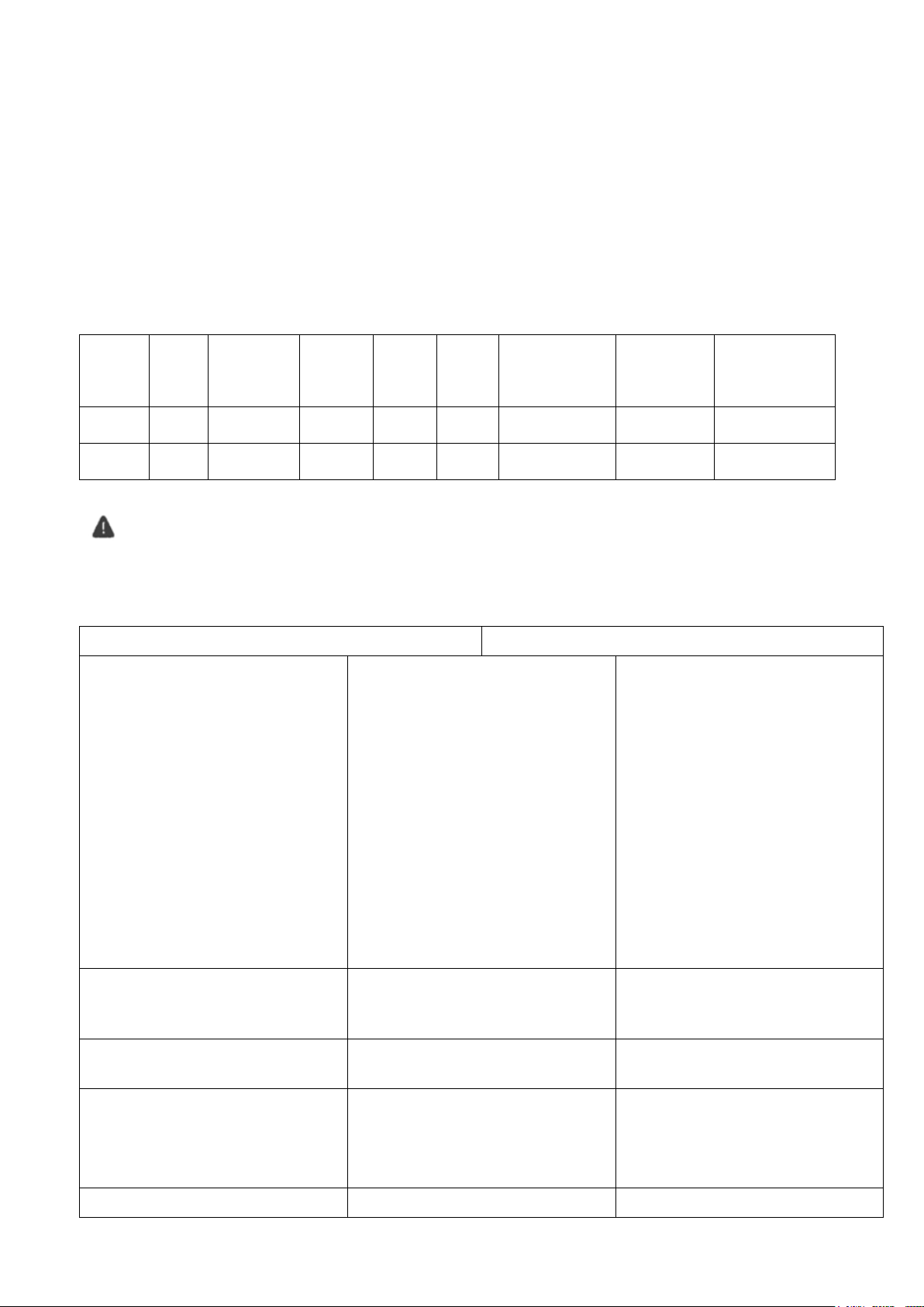
REPLACING FILTER CARTRIDGE ELEMENTS
MODEL
PART
NO.
ELEMENT
PART
NO.
FILTER
AREA
MAX
FLOW
RATE
G/Hr
MAX
FLOW
RATE
G/M
4 HR TURN
OVER
6 HR TURN
OVER
PUMP SIZE
UF 80
53945
78085 X 4
80 sq ft
5,520
92
22,080
33,120
750w
3000w
UF 100
53946
78086 X 4
100 sq ft
5,520
92
22,080
33,120
750w
3000w
PROBLEM
CORRECTION ACTION
AIR ENTERING THE FILTER
Correct any conditions in your filtration system
that allows air to enter the system
Low water level in pool or spa- skimmer is
starving for water with pump running. Add water
to pool or spa
Air bubbles or low water level in pump hair and
lint basket are caused by the following factors:
Low water level
Clogged skimmer basket
Split suction cleaner hose
Leak in pump hair and lint lid
Leak in pump suction line
Air bubbles coming out of water return lines into
pool or spa with pump running(see steps above)
LIMING UP
A stiffening of the fabric caused by mineral
deposits It usually is due to deposits of either
magnesium or calcium or both
Removal of these may be accomplished by
soaking the grids in six (6) parts water to one (1)
part hydrochloric acid (muriatic acid)
CLOUDY OF DIRT
A brief “cloud” of dirt may appear immediately
when the filter starts
This is a characteristic of Diatomite filters
SHORT FILTER RUNS
Until the water initially put into the pool has
been completely filtered, short filter runs are
normal
Plaster dust can be responsible for short filter
runs, requiring frequent cleaning
Elements may be loaded with oils, debris etc.
clean elements, refer to Cleaning Filter Elements
PRESSURE DROPS ON PRESSURE
If pressure drops on gauge, shut off power to
Filter cartridges element life will vary with pool/spa conditions such as bather load, wind, dust, etc. you can expect an average Element life
of 3 years under normal conditions.
To replace the elements, follow steps in the CLEANING FILTER ELEMENTS
PUMP PRIMING
With the pump OFF,
1. Remove the lid from the pump strainer and pour in approximately 1 gallon of water or until strainer is fully
covered
2. Replace the pump lid, ensuring it is fitted correctly
3. If valve(s) have been installed on the pump suction line, close before filling strainer. Open again after lid has been
securely fitted in place. Any valves on the return lines should be open. The pump should not need to be re-primed
unless the pump has been drained for servicing, or winterizing( refer to the pump instruction manual provided with
the pump)
NEVER LOOSEN THE CLAMP BAND WHEN PUMP IS OPERATING OR THE SYSTEM
IS UNDER PRESSURE
TROUBLESHOOTING
WARNING: THIS FILTER OPERATES UNDER HIGH PRESSURE.
When any part of the circulating system, (filter, pump, valves, clamp etc) are serviced, air can enter the system and become
pressurized. Pressurized air can cause the lid to be blown off, which can result in severe injury, death, or property damage.
NOTE;
Turn off power to the filtration system prior to attempting any service or repair
.
INST 412 UF ULTRA FINE Cartridge Filter V08-20
Page 9
9
GAUGE
pump and turn motor shaft with your fingers. If it
turns freely then the pump must be disassembled
and the impeller checked to see if it is clogged. If
it is not frozen or clogged then there is an
obstruction in the line between the pool and the
pump.
PRESSURE REMAINS HIGH AFTER
BACKWASH
If pressure remains high after backwash,
backwash filter again, if still high, treat for
conditions covered by LIMING UP above.
MAINTAIN YOUR PRESSURE GAUGE
IN GOOD WORKING ORDER
The pressure gauge is an important part of the
filter system. It is your primary indicator of how
the system is operating
Check the operation of your pressure gauge in
the following manner:
The pressure gauge should go to zero (0) when
the system is turned off and pressure is relieved.
The pressure gauge should indicate pressure
when the system is operating.
The pressure gauge should be readable and not
damaged in any way.
Replace the pressure gauge if it is not operating
correctly
DIATOMITE IS CONTINUOUSLY
ENTERING THE POOL
Inspect the elements for any tears and holes
Inspect the internal air bleed if broken
Inspect the elements and make sure the elements
are positioned vertically and properly seated
between the upper manifold and lower manifold.
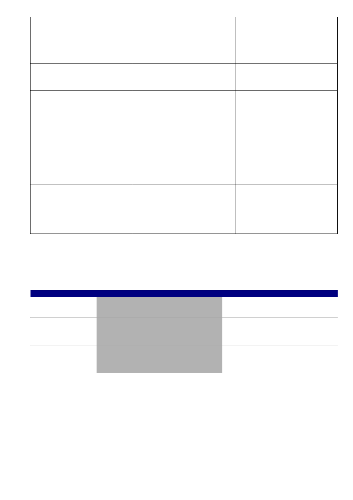
MAINTENANCEOF YOUR FILTER
Timing
Maintenance Check
Service action (if required)
Every 2 Weeks
Check pressure gauge. If pressure increase is
greater than 10-15 PSI cleaning may be required
In accordance with instructions, clean
elements with a high pressure cleaner or
purpose made element cleaner
Every 3 Months
Check inlet/outlet o’rings for leaks
Check operation of pressure gauge – salt water
can prematurely reduce the life of a gauge
Isolate Pump, turn power off, clean and
grease O rings or replace if necessary
Replace gauge if required
Once a Year
Compare operating pressure of a cleaned filter
to initial pressure (when new). Also check for
signs of damage to elements
If pressure is more than 8 – 10 PSI different
from cleaned elements to new filter, replace
elements
Maintenance Schedule: Your new product incorporates moving parts and withstands high velocity w ater with chemicals in
it. Some of these parts will wear in the normal course of use and require regular checks and maintenance. Performing
these checks and maintenance will identify parts that have worn and require repair/replacement before further serious
damage is sustained. A small amount of regular care and attention to your pool equipment will help ensure long life and
trouble free performance.
Important note: Regular maintenance is important to ensure long life and trouble free performance of your pool equipment.
If unable to perform the maintenance yourself, contact www.Jacuzzipool.com who will arrange a trained service technician to
perform the maintenance for you.
INST 412 UF ULTRA FINE Cartridge Filter V08-20
Page 10

10
INST 412 UF ULTRA FINE Cartridge Filter V08-20
Page 11

11
INST 412 UF ULTRA FINE Cartridge Filter V08-20
Page 12

12
Fluidra Group Australia Pty Ltd
219 Woodpark Road,
Smithfield. N.S.W. 2164
ABN 087 002 641 965
INST 412 UF ULTRA FINE Cartridge Filter V08-20
 Loading...