

Aston Martin V8 Vantage Workshop Manual
Workshop Manual
Issue 1
Aston Martin Lagonda Limited
Banbury Road, Gaydon, WARWICK, Warwickshire,
England, CV35 0DB
Telephone: (01926) 644700 Fax: (01926) 644733
Aston Martin are constantly seeking to improve the specification, design and production of their vehicles and alterations
take place accordingly. While every effort has been made to ensure the accuracy of this Manual, it should not be regarded
as an infallible guide to current specifications of any particular vehicle.
All rights reserved. No part of this publication may be reproduced, stored in a retrieval system or transmitted, in any form,
electronic, mechanical, photocopying, recording or other means without prior written permission from Aston Martin
Lagonda Limited.
The manufacturer reserves the right to vary specifications without notice in accordance with its policy of continual product
improvement.
Produced by the Technical Publications Department
Aston Martin Lagonda Limited
Issue 1 - October 2005 DVD Part No. 6G43-43-10055

Contents
October 2005 Workshop Manual 0-0-3
V8 Vantage Workshop Manual
Contents
Introduction
Welcome..............................................................0-0-6
Safety Precautions.................................................0-0-7
Lifting and Jacking.................................................0-0-9
Vehicle Recovery ................................................0-0-10
Vehicle Identification Number ............................0-0-11
Body System (01.00)
Body Structure (01.01)..........................................1-1-3
Front End System (01.02) ......................................1-2-1
Body Closures (01.03)...........................................1-3-1
Interior Trim (01.05) .............................................1-4-1
Exterior Trim (01.08)............................................. 1-5-1
Mirrors (01.09)......................................................1-6-1
Seating (01.10)......................................................1-7-1
Glass, Frame and Mechanism (01.11)....................1-8-1
Instrument Panel (IP) (01.12).................................1-9-1
Handles and Lock Mechanisms (01.14) ...............1-10-1
Wipers and Washer System (01.16).....................1-11-1
Bumpers (01.19) .................................................1-12-1
Restraining Devices (01.20).................................1-13-1
Frame and Mounting (02.00)
Subframes (02.03).................................................2-1-2
Engine Assembly (03.00) .......................................4-3-1
Engine System (03.00)
Engine Structure (03.01)........................................3-1-1
Lubrication System (03.02)....................................3-2-1
Cooling System (03.03) .........................................3-3-1
Fuel Charging System (03.04)................................3-4-1
Accessory Drive System (03.05).............................3-5-1
Engine Cranking System (03.06) ............................3-6-1
Ignition System (03.07) .........................................3-7-1
Emission Control (03.08) .......................................3-8-1
Valve Train (03.09) ...............................................3-9-1
Engine Sealing (03.10).........................................3-10-1
Power Conversion (03.11)...................................3-11-1
Air Charging (03.12)............................................3-12-1
Evaporative Emissions (03.13) .............................3-13-1
Engine Management System (03.14)....................3-14-1
Throttle Control (03.16) ......................................3-15-1
Suspension (04.00)
Road Wheel Alignment (04.00) .............................4-1-2
Front Suspension (04.01).......................................4-2-1
Rear Suspension (04.02)........................................4-3-1
Road Wheels and Tyres (04.04) ............................4-4-1
Driveline (05.00)
Driveshaft (05.01) .................................................5-1-2
Rear Drive System (05.02).....................................5-2-1
Halfshafts (05.05)..................................................5-3-1
Brake System (06.00)
Description........................................................... 6-1-2
Front Disc Brake (06.03) ....................................... 6-2-1
Rear Disc Brakes (06.04)....................................... 6-3-1
Hand Brake (06.05) .............................................. 6-4-1
Brake Actuation System (06.06) ............................6-5-1
Power Brake System (06.09) .................................6-6-1
Transmission (07.00)
Automatic Transmission (07.01) ............................7-1-2
Transmission Cooling (07.02) ................................ 7-2-1
Manual Transmission (07.03) ................................7-3-1
Automatic Control System (07.05).........................7-4-1
Clutch (08.00)
Clutch Controls (08.02).........................................8-2-1
Exhaust (09.00)
Exhaust Overview .................................................9-1-2
Silencer Assembly (09.01) ..................................... 9-1-3
Pipes and Supports (09.03) ...................................9-2-1
Fuel (10.00)
Fuel Tank and Lines (10.01)................................10-1-2
Steering (11.00)
Steering Gear (11.01)..........................................11-1-2
Power Steering (11.02)........................................ 11-2-1
Steering Column (11.04) .....................................11-3-1
Steering Column Switches (11.05).......................11-4-1
Steering Wheel (11.06) ....................................... 11-5-1
Climate Control (12.00)
Body Ventilation system (12.01)..........................12-1-3
Heater System (12.02) ........................................12-2-1
Air Conditioning (A/C) System (12.03).................12-3-1
A/C Control System (12.04).................................12-4-1
Information, Gauge and Warning (13.00)
Instrument Cluster (13.01) .................................. 13-1-2
Power Supply (14.00)
Battery System (14.01) ........................................14-1-2
Alternator and Regulator System (14.02) .............14-2-1
Vehicle Entertainment (15.00)
Audio System......................................................15-1-1
Vacuum Distribution (16.00)
Body Vacuum System (16.01) ............................. 16-1-1
Lighting (17.00)
Front Lights (17.01)............................................. 17-1-2
Interior Lighting (17.02) ......................................17-2-1
Rear Lights (17.03).............................................. 17-3-1
Lighting Mechanisms (17.04)...............................17-4-1

Contents
0-0-4 Workshop Manual October 2005
Electric Distribution/Electronic Control (18.00)
Wiring and Circuit Protection (18.01) ................. 18-1-2
Vehicle Control System (18.08) .......................... 18-2-1
Electronic Features (19.00)
Active Anti-Theft System (19.01)......................... 19-1-2
Appendix & Glossary
Fluids/Capacities................................................. 20-1-2
Abbreviations ..................................................... 20-1-3
Terms................................................................. 20-1-3
Special Tools - Pictorial Index............................. 20-1-4
Specialist Tool Operation ................................... 20-1-6
Maintenance Schedules...................................... 20-1-7
Torque Table...................................................... 20-1-9
Torque Conversion Tables................................ 20-1-10

Contents
October 2005 Workshop Manual 0-0-5
Introduction
Contents .................................................................0-3
Welcome................................................................0-0-6
Chapters .................................................................0-6
Chapter Navigation................................................0-6
Page Numbering..................................................... 0-6
Systems Classification Coding................................ 0-6
Special Tools..........................................................0-0-6
Location References................................................ 0-6
Warnings, Cautions and Notes..............................0-0-6
Repairs and Replacements ..................................... 0-6
Safety Precautions .................................................0-0-7
Battery Disconnection ............................................ 0-7
Air Conditioning (A/C) System................................0-7
Chemical Handling and Storage.............................0-7
Electrical Equipment..............................................0-0-7
Exhaust Fumes........................................................ 0-7
Fire Precautions...................................................... 0-7
Tools and Equipment.............................................0-0-8
Used Engine Oil...................................................... 0-8
Health protection precautions................................ 0-8
Environmental Protection.......................................0-8
Lifting and Jacking .................................................0-0-9
Safety ......................................................................0-9
Jacking Points ........................................................0-0-9
Lifting.....................................................................0-0-9
Workshop Hoist.....................................................0-9
Workshop Jack....................................................... 0-9
Stands.................................................................... 0-9
Vehicle Recovery..................................................0-0-10
General................................................................. 0-10
Transporting .........................................................0-10
Suspended Towing............................................... 0-10
Adhere to Towing Regulations..............................0-10
Towing by Another Vehicle..................................0-10
Vehicle Identification Number ............................0-0-11
VIN Number Location..........................................0-11
Welcome
0-0-6 Workshop Manual October 2005
Welcome
This Workshop Manual is part of a suite of technical manuals
provided for V8 Vantage. Other technical manuals include:
• Parts manual
• OBDII Diagnostic manual
• Man hour schedules
Chapters
Each chapter in this workshop manual is associated with a 4
digit number, i.e. Transmission (07.00). Each chapter is then
further broken into sections, i.e. Automatic Transmission
(07.01).
Chapter Navigation
Example 1:
Older workshop manuals would have Steering and
Suspension together in one chapter. The structure now used
places Steering and Suspension into their own chapters.
When required references are made out to other chapters.
Page Numbering
The page numbering system used within this workshop
manual is as follows:
Systems Classification Coding
Alongside the ‘System’ and ‘Subsystem’ section titles appear
codes. For example Exhaust ‘09.00’ or Power Steering
‘11.02’. These codes relate to a Corporate Product Systems
Classification (CPSC) and are designed to segregate the parts
for engineering release and organise a variety of engineering
data.
Special Tools
Where special service tools are required to perform an
operation, the tool number is recorded at the point of use
within the procedure. Where the operation of a special
service tool is complicated or not obvious, refer to Appendix
and Glossary for detailed operation procedures. A pictorial
list of special service tools available for this vehicle can also
be found in Appendix and Glossary.
Location References
References to left, right, front or rear of the vehicle or of a
component are referenced from sitting in the drivers seat
facing forward. Any such references to assemblies removed
from the vehicle are to the normal orientation of the
assembly when installed in the vehicle.
The following Warnings, Cautions and Notes are used within
this Owner’s Guide to call your attention to specific types of
information.
Warnings, Cautions and Notes
Warnings
Cautions
Notes
Repairs and Replacements
Where replacement parts are required, it is essential that
only genuine Aston Martin parts are used. Your attention is
drawn to the following points concerning repairs and the
fitting of genuine Aston Martin parts and accessories:
• Safety features embodied in the vehicle may be impaired
if other than genuine Aston Martin parts are installed. In
certain territories, legislation prohibits the fitting of parts
which are not produced to the manufacturers
specification
• Adhere to torque wrench settings given in this manual
• Locking devices, where specified, must be installed. If the
efficiency of a locking device is impaired during removal,
it must be renewed
• The vehicle warranty may be invalidated by the
installation of other than genuine Aston Martin parts
3- 2- 5
System, i.e. Engine system
Subsystem, i.e. Engine lubrication system
Page Number, i.e. Number within subsystem
Warning
Identifies procedures which must be followed precisely
to help avoid the risk of personal injury.
Caution
Provided to indicate procedures which must be followed
precisely to reduce the possibility of damage to the
vehicle.
Provided to indicate procedures which will help to avoid
difficulties in the operation of the vehicle.
Safety Precautions
October 2005 Workshop Manual 0-0-7
Safety Precautions
All service workshops are a source of potential danger and
repair work should only be performed by technically trained
staff following procedures detailed in this manual. A safety
conscious approach to the performance of all service
procedures must be observed at all times. Statutory
requirements governing all aspects of health and safety at
work including directives for the proper use of materials and
equipment must be implemented.
The following contains a list of particular safety precautions
which should be observed; it is not intended to be
exhaustive.
Battery Disconnection
When a service manual procedure requires the vehicle
battery to be disconnected - always physically disconnect
the vehicle battery earth (Negative) lead.
Do not use the ‘Battery Disconnect Switch’.
After reconnecting the vehicle battery the following items
will have to be reset or re-learnt:
•Radio pre-sets
•Windows
• DTCs will be lost
Air Conditioning (A/C) System
Do not break into the A/C refrigeration system until the
refrigerant has been evacuated using the procedure detailed
in this manual. Do not disconnect any A/C refrigerant system
pipes unless trained and instructed to do so. The refrigerant
used can cause blindness if allowed to contact your eyes.
Chemical Handling and Storage
Chemicals used in the servicing of motor vehicles include
acids, adhesives, antifreeze, brake fluids, coolants, grease,
oil, paint, resin and solvents. Exposure to certain chemicals
through direct contact or inhalation can be fatal.
Potential hazards may also be present through the incorrect
use, storage and handling of chemicals causing a fire risk.
The following precautions should be observed.
• Strictly adhere to handling and safety information found
on containers and labels.
• Do not store chemicals in unlabelled or incorrectly
labelled containers.
• Containers used for storing chemicals should not be left
open; there is a risk of spilling, or evaporation of fumes
which may be inflammable or toxic.
• Do not mix chemicals unless instructed to do so following
manufacturers guidelines.
• Do not inhale chemical materials to determine identity,
they may be toxic.
• Do not use petrol, kerosene, diesel fuel, gas oil, thinners
or solvents for washing skin.
• Containers whose capacity is over 25 litres (5 gallons)
require a bund wall in order to contain spillages.
• Chemicals based on solvents such as paint should not be
sprayed in a confined space; work areas used for such
operations should be well ventilated and fume extraction
equipment should be utilised.
• Ensure that adequate ventilation is provided when volatile
de-greasing agents are being used.
• Avoid splashing the skin, eyes and clothing.
• Clean chemicals from the skin and clothing as soon as
possible after soiling.
• Wear protective clothing such as goggles, non porous
gloves and apron when handling battery acid and other
corrosive and toxic substances.
Electrical Equipment
• Ensure that electrical equipment is in safe working order
before use.
• Inspect power leads of all mains electrical equipment for
damage and security, and check that it is properly
earthed.
• Ensure that electrical equipment is protected by a fuse of
the correct current rating.
• Disconnect the battery before commencing repair
operations to the electrical system, fuel system and engine
or when working beneath the vehicle.
Exhaust Fumes
Engines should not be run in confined spaces, exhaust fumes
contain harmful and toxic substances including carbon
monoxide which can prove fatal if inhaled. Engines must
only be run where there is fume extraction equipment in
operation or where there is adequate ventilation.
Fire Precautions
• Ensure that a suitable form of fire extinguisher is
conveniently located near the work area.
• Keep oils, solvents and combustible materials away from
naked flames and other sources of ignition.
• Ensure that NO SMOKING signs are posted around areas
where combustible materials and vapour may be present
and ensure that the warnings are strictly observed.
• Ensure that dry sand is available to soak up any spillage of
fuel or other flammable solutions.
• Fume extraction equipment must be available and in full
working order to remove combustible and toxic vapours.
• All personnel should be aware of the fire drill procedures
and precautions.
Warning
Do not smoke in the vicinity of volatile de-greasing
agents.
Warning
Fume extraction equipment must be in operation when
solvents are used e.g. trichloroethane, white spirit,
SBP3, methylene chloride, perchlorethylene.

Safety Precautions
0-0-8 Workshop Manual October 2005
Tools and Equipment
• Do not leave tools, equipment, spilt oil, etc. around or on
the work area.
• Ensure that tools and equipment used are in good
condition; do not use damaged or defective tools or
equipment.
• Do not apply heat in an attempt to free stiff nuts or fittings;
as well as causing damage to protective coatings, the stray
heat may damage electronic equipment, harnesses and
brake lines.
• Use the recommended service tool where instructed to do
so.
Used Engine Oil
Prolonged and repeated contact with mineral oil will result
in the removal of natural fats from the skin, leading to
dryness, irritation and dermatitis. In addition, used engine
oil contains potentially harmful contaminants which may
cause skin cancer. Adequate means of skin protection and
washing facilities should be provided.
Health protection precautions
• Avoid prolonged and repeated contact with oils,
particularly used engine oil.
• Wear protective clothing, including impervious gloves
where practicable.
• Do not put oily rags in pockets.
• Avoid contaminating clothes with oil.
• Overalls must be cleaned regularly. Discard un-washable
clothes and oil impregnated footwear.
• First aid treatment should be obtained immediately for
open cuts or wounds.
• Use barrier creams, apply before each work period to help
the removal of oil from the skin.
• Wash with soap and water to ensure all oil is removed.
Preparations containing lanolin replace the natural skin
oils which have been removed.
• Do not use petrol, kerosene, diesel fuel, gas oil, thinners
or solvents for washing skin.
• If skin disorders develop, obtain medical advice.
• Where practicable, degrease components prior to
handling.
• Where there is a risk of eye contact, eye protection should
be worn. In addition, an eye wash facility should be
provided.
Environmental Protection
It is illegal to pour used oil on the ground, down sewers or
drains, or into water courses. The burning of used engine oil
in small space heaters or boilers is not recommended unless
emission control equipment is installed; in case of doubt,
contact the Local Authority for advice on disposal facilities.
Lifting and Jacking
October 2005 Workshop Manual 0-0-9
Lifting and Jacking
Safety
• Recommended procedures for lifting, jacking and
towing must be strictly observed to ensure personal
safety.
• Always use a vehicle hoist, ramp or pit for working
beneath the vehicle in preference to jacking.
• Never rely on a jack to support a car independently, use
axle stands or blocks carefully placed at jacking points
to provide rigid support.
• When working beneath a vehicle, chock wheels as well
as applying handbrake.
• Ensure vehicle is standing on firm, level ground before
jacking or lifting.
• Check lifting equipment has adequate capacity for load
being lifted and is in full working order.
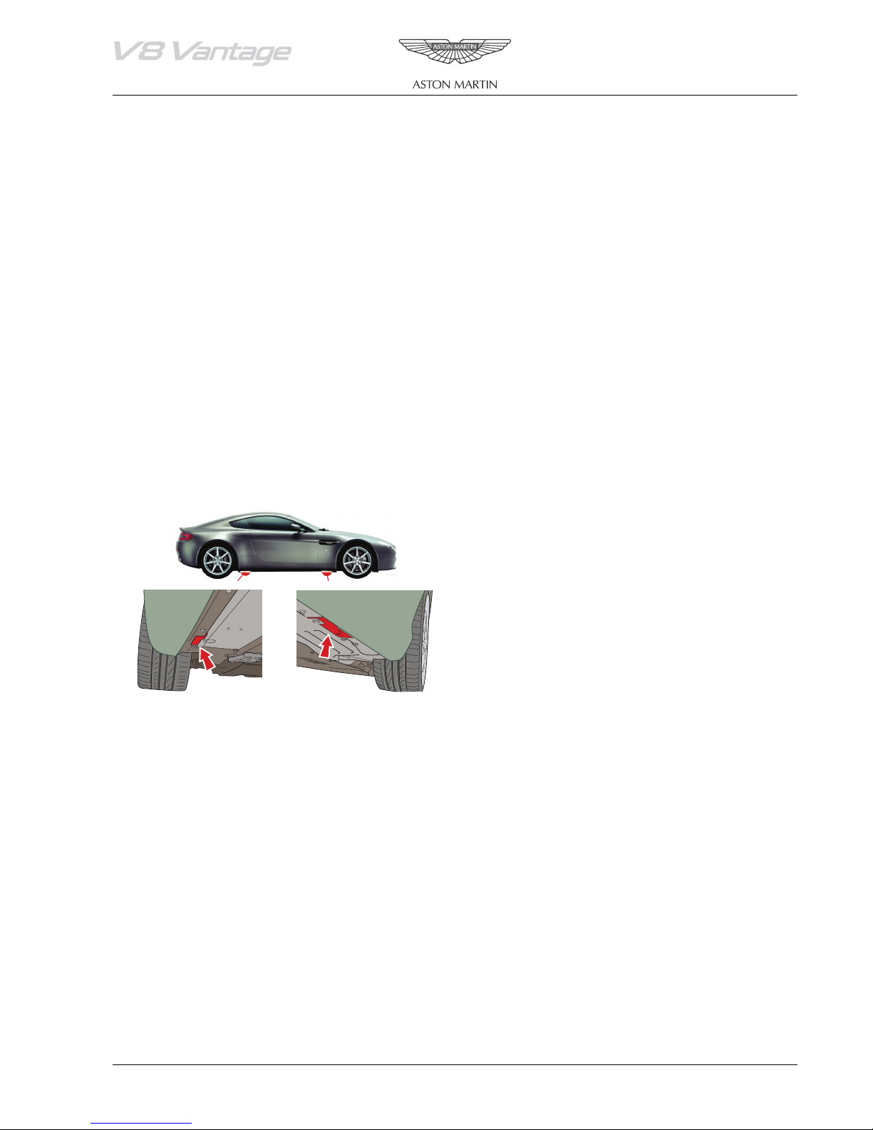
Jacking Points
This vehicle jacking points are at positions shown.
May also be jacked on the front subframe front crossmember
Always use a jack with a rubber contact pad. Avoid use of
jacks with sharp contact pads which would damage floor
pan Always chock the opposite road wheels as well as
applying the handbrake when using a hydraulic jack.
To prevent body distortion, avoid single point or one side
jacking with the tunnel shear panel removed.
Lifting
Workshop Hoist
Use of a workshop hoist is recommended for all operations
where vehicles must be raised. Follow manufacturers
instructions. If using an adjustable arm type, ensure lifting
pads are correctly positioned at the four jacking points
before lifting.
Workshop Jack
To avoid any danger of bodywork damage when using a
hydraulic jack, the vehicle must only be lifted at the jacking
points.
Stands
When carrying out work (other than a wheel change) which
requires a wheel to be raised, a stand must be used, located
at the jacking point, to provide a secure support for the
vehicle.
Vehicle Recovery
0-0-10 Workshop Manual October 2005
Vehicle Recovery
General
Preferred method of vehicle recovery is by flat bed
transporter.
The towing eye is primarily for emergency use when towing
for short distances, e.g. removing vehicle if it is causing an
obstruction or winching vehicle onto a flatbed transporter.
If moving this vehicle in such a situation, install the towing
eye to the bracket in the lower grille aperture.
Transporting
If vehicle is to be transported on a trailer or flat bed
transporter the handbrake must be applied and the road
wheels must be chocked.
Suspended Towing
Take care when using 'spectacle frame' type towing
equipment that the towing device is well clear of front or
rear apron. Body damage may occur if vehicle passes over
uneven road surfaces.
Rear Suspended Tow
1. Set the steering in the ‘straight ahead’ position.
Remove the ignition key from the ignition. Ensure the
steering is locked in the straight ahead position.
2. Raise the vehicle using a 'spectacle frame' style lifting
device where a cradle is positioned under each rear
wheel as indicated below.
Adhere to Towing Regulations
In certain countries the registration number of towing
vehicle and an ‘ON TOW’ sign or warning triangle must be
displayed in a prominent position at the rear of vehicle being
towed.
Towi ng b y An o the r Ve h icl e
This vehicle may be towed short distances by another
vehicle provided that a speed of 48 km/h (30 mph) is not
exceeded. Ensure the towed vehicle gear selection is in
‘Neutral’ (manual) or position ‘N’ (automatic) with ignition
key turned to position ‘II’ to release steering lock and to
render horn, indicators and brake lights operational.
Caution
Take care to protect the paint work when installing the
towing eye. Ensure the towing eye is tight.
Caution
Do not tow with ‘sling’ type equipment as this
could result in damage to the bodywork.
Warning
When the engine is not running, the steering will no
longer be power-assisted and the brake booster will
become ineffective after a few applications of the
brakes. Be prepared for relatively heavy steering and
the need for greatly increased brake pedal pressure.
Vehicle Identification Number
October 2005 Workshop Manual 0-0-11
Vehicle Identification Number
The Vehicle Identification Number (VIN) is a 17 character number which uniquely identifies the vehicle and gives
fundamental data on the build site, date and initial configuration of the vehicle.
VIN Number Location
The VIN number is shown on two labels in the vehicle:
1 Under the lower edge of the windscreen.
2 Front of the engine bay.
• The VIN number is also engraved on the floorpan in the
right front footwell.
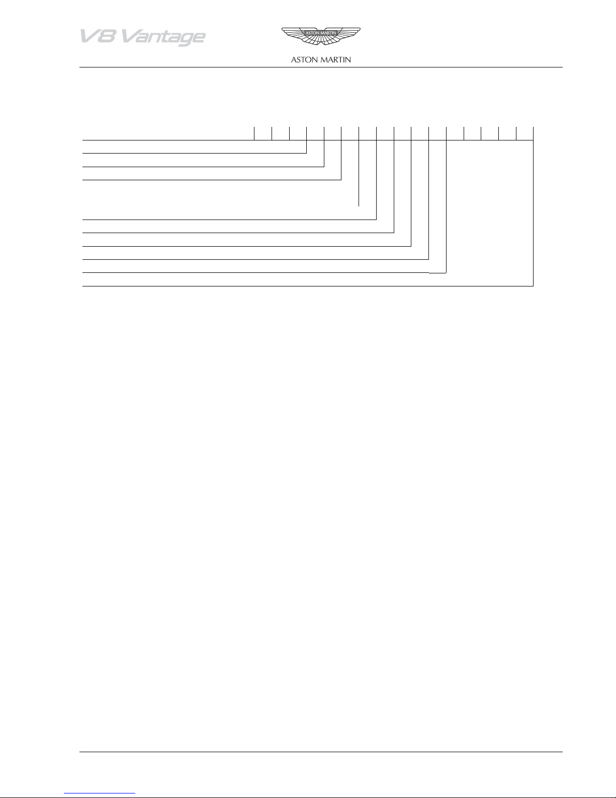
SCFBC3A45GC00001
Code for AML
Restraint System
Transmission and Steering
Body Type
Engine Type
Calculated Check Digit
Model Year
Manufacturing Plant
Series Identifier
Sequential Chassis Number
Body System (01.00)
Contents
Body Structure (01.01)...........................................1-1-3
Undertray Vehicle Set-Renew ................................ 5-2
5-2
Overview ................................................................1-3
RH/LH Front Wheel Arch Liner-Renew ..................
Front End (01.02)...................................................1-2-1
RH/LH Rear Wheel Arch Liner-Renew ................... 5-2
Front Wings ............................................................2-1
Specifications.........................................................2-1
Specifications ......................................................... 6-1
Body Closures (01.03) ...........................................1-3-1
Maintenance........................................................... 6-1
6-1
6-1
Tailgate.................................................................. 3-1
7-1
7-1
7-1
7-1
Specifications.......................................................... 3-1
RH/LH Door Mirror Assembly-Renew ....................
Doors ....................................................................3-1
Door Mirror Glass and Pad Assembly-Renew .........
Bonnet................................................................... 3-1
Description.............................................................
Maintenance........................................................... 3-2
Heated Seats .........................................................
Tailgate Assembly-Renew....................................... 3-2
Specifications ........................................................
Hood Assembly-Renew.......................................... 3-2
Maintenance...........................................................
Interior Trim (01.05)..............................................1-4-1
Maintenance........................................................... 4-1
Rear Centre Console-Renew
8-1
8-1
8-1
8-1
8-1
8-1
8-1
8-2
8-2
Door Trimboard Assembly-Remove for Access/Refit4-3
9-1
9-1
........................................ 9-1
9-6
9-6
9-6
.......................... 9-6
new ....................................................................... 4-5
9-7
9-7
9-8
.................................... 9-8
9-8
......................................... 9-9
..................................4-1
Description.............................................................
RH/LH Front Sill Plate-Renew ................................ 4-1
Frameless doors .....................................................
RH/LH Front Sill Name Plate-Renew ...................... 4-1
Specifications.........................................................
Header Panel Assembly-Renew..............................4-1
Maintenance...........................................................
RH/LH Upper Rear Pillar Panel Assembly-Renew ...4-2
Glass Regulator ......................................................
RH Sun Visor-Renew ............................................. 4-2
RH/LH Door Glass-Renew .....................................
LH Sun Visor-Renew.............................................. 4-2
Door Glass-Adjust/Reset.........................................
Rear Header Panel Assembly-Renew...................... 4-3
Front Windshield-Renew .......................................
Door Trimboard Assembly-Renew..........................4-3
Rear Windshield-Renew ........................................
RH/LH Door Trim Upper Veneer Panel-Renew ...... 4-4
Specifications .........................................................
LH Door Trim Upper Panel-Renew........................4-4
Maintenance...........................................................
RH/LH Interior Door Assembly Handle and Armrest-Re-
Instrument Panel-Renew
new ....................................................................... 4-4
Driver Upper Inner Panel Assembly-Renew............
RH/LH Door Pocket Assembly-Renew.................... 4-4
Driver Outer Upper Panel Assembly-Renew ..........
Lower Panel Assembly Quarter Trim-Renew ..........4-4
Passenger Upper Panel Assembly-Renew ...............
RH/LH Middle Section Quarter Trim Panel Assembly-Re-
Passenger Panel Assembly-Renew
RH/LH Upper Quarter Moulding Trim-Renew........4-5
Driver Lower Panel Assembly-Renew.....................
RH/LH Rear Heel Board Assembly-Renew..............4-5
Airbag Panel and Door Assembly-Renew ...............
Tailgate Lid Trim Assembly-Renew......................... 4-5
Instrument Cluster Hood Assembly-Renew.............
RH/LH Side Luggage Compartment Carpet Assembly-Re-
Glovebox Assembly-Renew
new ....................................................................... 4-5
Knee Protector-Renew...........................................
Luggage Compartment Front Carpet Assembly-Renew4-6
Glovebox Shield-Renew
Mirrors (01.09) ......................................................1-6-1
Seating (01.10).......................................................1-7-1
RH/LH Front Seat-Renew....................................... 7-1
Glass, Frame and Mechanism (01.11)................... 1-8-1
Instrument Panel (IP) (01.12)................................1-9-1
............... Passenger Lower Panel Assembly-Renew9-7
Luggage Compartment Floor Rear Carpet Assembly-Renew
Glove Compartment Damper Spring-Renew .......... 9-9
4-6
Cluster Bezel Panel-Renew .................................... 9-9
9-10
9-10
9-10
Tailgate Scuff Plate-Renew ..................................... 4-6
Driver Panel Assembly-Renew .............................
LH Side front Carpet Assembly-Renew...................4-6
Instrument Panel Bezel Assembly-Renew .............
Centre Stack Assembly-Remove for Access/Refit..... 4-6
Radio Speaker Grille Assembly-Renew .................
Exterior Trim (01.08) .............................................1-5-1
Maintenance
9-11
9-11
9-11
9-11
9-11
RH Wing Side Strake-Renew.................................. 5-1
10-1
10-1
10-1
........................................................... 5-1
Console Panel Assembly-Renew...........................
Radiator Grille-Renew............................................5-1
Master Lock Switch-Renew ..................................
RH/LH Hood Mesh Assembly-Renew..................... 5-1
IDV Control Switch-Renew ..................................
RH Side Strake Mesh-Renew..................................5-1
Heated Front Screen Switch-Renew.....................
LH Side Strake Mesh-Renew..................................5-1
PDC Off Switch-Renew .......................................
LH Wing Side Strake-Renew .................................. 5-1
Description...........................................................
Front Undertray-Renew .........................................5-2
Vehicle Key/Remote Transmitter ..........................
Rear Undertray-Renew .......................................... 5-2
Central Locking System........................................
Glovebox Open Switch-Renew............................ 9-11
Handles and Lock Mechanisms (01.14) .............. 1-10-1
October 2005 Workshop Manual 1-1-1

Remote Transmitter..............................................10-1
Fuel Filler Assembly..............................................10-1
Boot Emergency Release ......................................10-1
Specifications........................................................10-2
Maintenance .........................................................10-2
RH/LH Front Door Latch Assembly-Renew ...........10-2
0114BD|Latch Assembly - Hood - Renew............10-2
RH/LH External Front Door External-Renew .........10-2
Reduced Guard Switch-Renew.............................10-3
Passenger Airbag On/Off Switch-Renew ...............10-3
Tailgate Release Switch-Renew.............................10-3
Passenger Window Lift Switch-Renew ..................10-3
Driver Window Lift Switch-Renew........................10-3
Wipers and Washer System (01.16).................... 1-11-1
Headlamp Washing ..............................................11-1
Windscreen Reservoir and Motor Assembly-Renew11-3
Headlamp Wash Motor and Pump Assembly-Renew11-4
Specifications........................................................11-2
Maintenance .........................................................11-2
Windscreen Wiper Motor Assembly-Renew..........11-2
Wiper Linkage Assembly-Renew...........................11-2
Driver Wiper Arm Assembly-Renew .....................11-2
Passenger Wiper Arm Assembly-Renew................11-3
Windshield Wash Filler Neck-Renew....................11-3
Low Level Water Sensor-Renew ...........................11-3
Washer Fluid Reservoir-Renew.............................11-4
Bumpers (01.19) ................................................. 1-12-1
Front Bumper........................................................12-1
Rear Bumper.........................................................12-1
Specifications........................................................12-2
Maintenance .........................................................12-2
Front Bumper Cover-Renew.................................12-2
Rear Bumper Cover-Renew..................................12-2
RH/LH Rear Lower Bumper Mesh-Renew.............12-3
Rear Diffuser-Renew ............................................12-3
Rear Lower Assembly Centre Mesh-Renew...........12-3
Restraining Devices (01.20)................................ 1-13-1
Seat Belts...............................................................13-1
Emergency Locking Retractor (ELR).......................13-2
Airbag System .......................................................13-3
Maintenance .........................................................13-4
Driver’s Airbag Module-Renew.............................13-4
Passenger Airbag-Renew.......................................13-4
Side Impact Door ARS Sensor Assembly-Renew....13-5
1-1-2 Workshop Manual October 2005
Body Structure (01.01)
Body System (01.00)
Body System (01.00)
Body Structure (01.01)
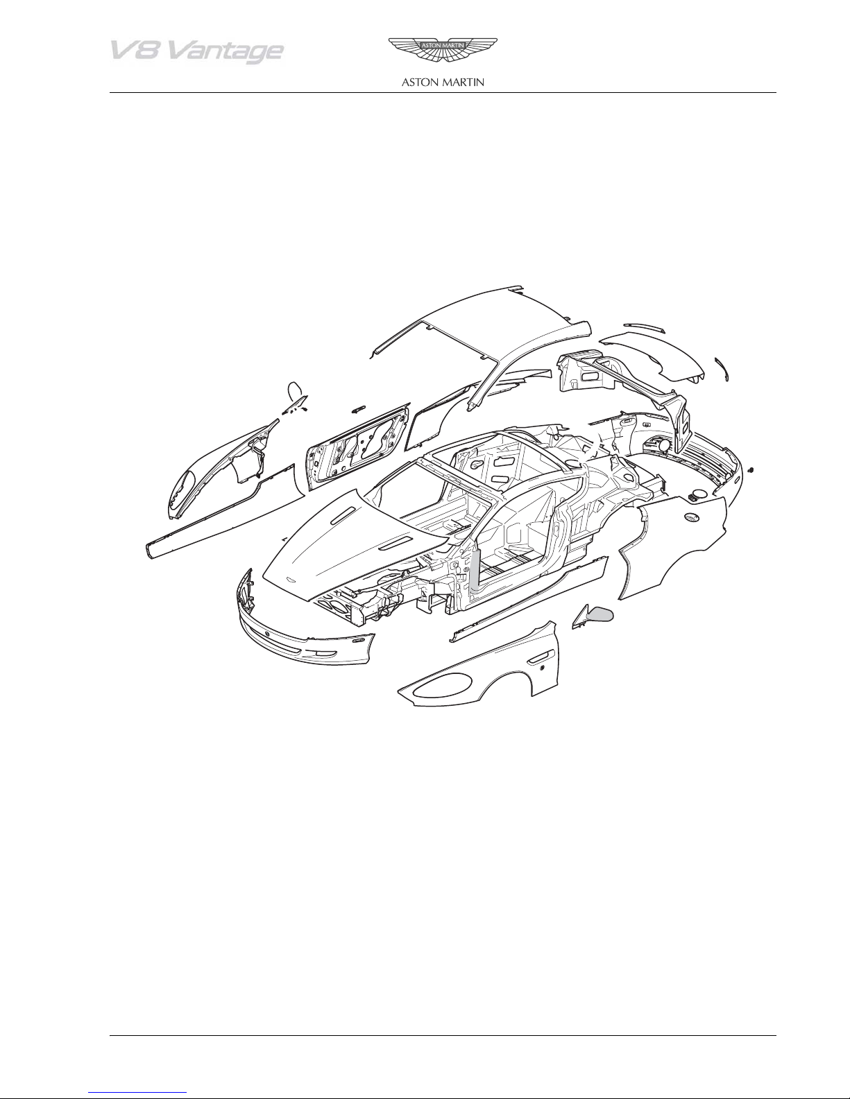
Overview
The all aluminium body underframe is bonded using an immensely strong hot-cured XD4600 red adhesive.
The rear quarter panels, roof and side mouldings are bonded to the structure using cold-cured 2810 MV adhesive. The
curing cycle is improved by using a hot air impingement system.
The composite front wings are bolted to the structure.
At no time should the body structure be subjected to temperatures in excess of 120°C (248°F).
01-01-020
October 2005 Workshop Manual 1-1-3

Body Structure (01.01)
Body System (01.00)
1-1-4 Workshop Manual October 2005
Front End (01.02)
Body System (01.00)
Body System (01.00)
Front End (01.02)
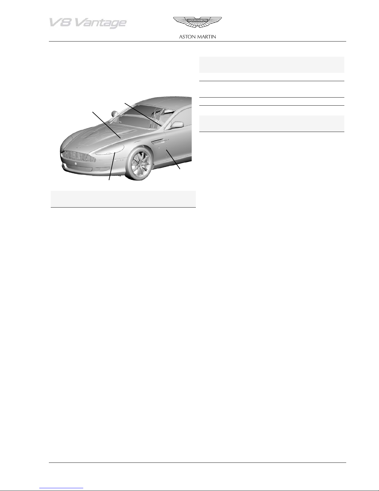
Wing Standard (mm)
Item 1 2 3 4
Front Wings
Tolerance ±0.75 +0.5 / -0.0 ± 0.75 ±0.5
Specifications
Flush -0.0 0.0 0.0 -0.5
Tolerance ±1.5 +0.0 / -0.5 ±1.5 ±0.5
Taper N/A
Symmetry N/A
Torque Figures
Description Nm
Wing Top 8
Wing Top Single nut Tight with
‘Threadlock’
Lower Rear 8
Slam panel 8
PCM Bracket 10
Bonnet Damper 25
Wing Standard (mm)
1
2
4
3
Item 1 2 3 4
Nominal gap 3.5 2.0 3.75 3.0
October 2005 Workshop Manual 1-2-1

Front End (01.02)
Body System (01.00)
1-2-2 Workshop Manual October 2005
Body Closures (01.03)
Body System (01.00)
Body System (01.00)
Body Closures (01.03)
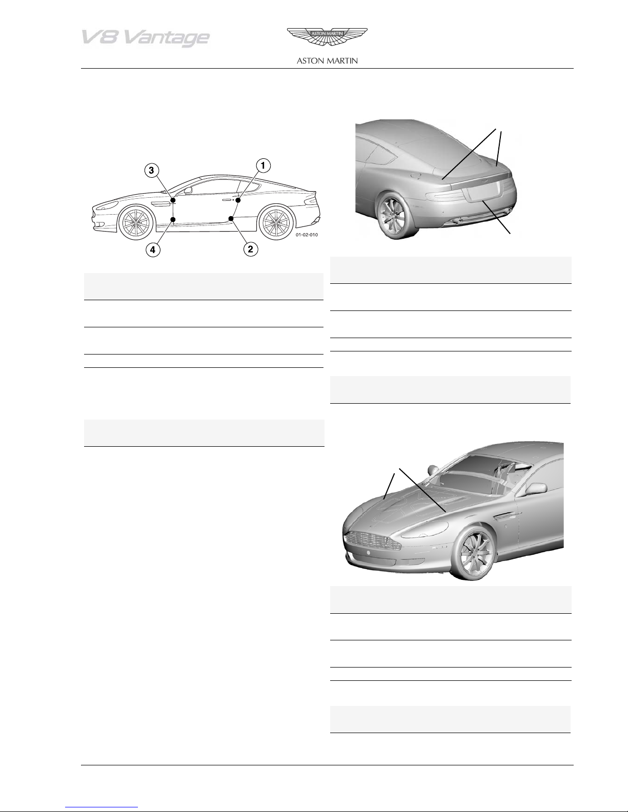
Tail ga te
Specifications
Doors
2
1
Tailgate Standard (mm)
Door Standard (mm)
Item 1 2
Item 1 *2 3 4
Nominal gap 3.5 3.5
Nominal gap 3.5 3.00 3.00 3.75
Tolerance ±0.75 ±1.0
Tolerance ±0.75 ±1.0 ±1.0 ± 0.75
Flush -0.5 N/A
Flush 0.0 -1.0 -1.0 0.0
Tolerance +0.5 / -1.0 N/A
Tolerance ±1.5 / 0.0 +0.0 / -1.0 ±1.0 ±1.5
Taper 1 mm Max. across the length
Taper N/A
Symmetry 1 mm Max. difference LH to RH
Symmetry N/A
* Flushness blends to 0.0 at the rear quarter
Torque Figures
* Gap blends to 3.5 at rear quarter
Description Nm
Hinge to Body 25
Torque Figures
Bonnet
Description Nm.
Hinge to Door 47.5
Hinge to Body 36
Door Striker plate
1
Bonnet Standard (mm)
Item 1
Nominal gap 3.5
Tolerance ±0.75
Flush -0.0
To le r an ce ± 1 .5
Taper N/A
Symmetry N/A
Torque Figures
Description Nm.
Hinge to Body 25
October 2005 Workshop Manual 1-3-1
Body Closures (01.03)
Body System (01.00)
Maintenance
Installation
Tailgate Assembly-Renew
1. Position hood to hinge and install bolts (x4).
2. Install hood ball studs.
Repair Operation Time (ROT)
Item Code
Tailgate Assembly-Renew 01.03.GG
3. Install Buffers to hood.
4. Install sound deadening.
5. Align hood to aperture.
Removal
6. Raise hood. Nip up one hinge bolt either side.
1. Remove RH quarter upper trim panel (see Workshop
7. Lower hood and check alignment.
Manual Procedure 01.05.CX Moulding Assembly -
8. Raise hood and tighten hinge bolts (x4) and tighten.
Quarter Trim Upper - RH - Renew).
9. Install gas struts.
2. Remove LH quarter upper trim panel.
10. Close bonnet to check engagement of latch assembly,
3. Remove rear header trim panel.
adjust if necessary.
4. Disconnect LH and RH tailgate harnesses in cabin
11. Close hood and check operation of hood release lever.
5. Remove LH and RH harness grommets from body shell
6. Remove tailgate trim panel (see Workshop Manual
Procedure 01.05.EF Trim - Tailgate Lid Assembly Renew).
7. Disconnect one multiplug and remove securing bolts
(x3) for GPS aerial and place to one side.
8. Disconnect multiplug and remove securing nuts (x2) for
central high stop lamp assembly, place to one side.
9. Disconnect multiplug and remove securing nuts (x2) for
tailgate release switch, place to one side.
10. Remove tailgate buffer stops and place to one side.
11. Provide collision protection between tailgate corners
and bodywork.
12. With assistance remove bolts (x4) from hinges and place
tailgate to one side.
Installation
1. With assistance align tailgate to hinges and install bolts
(x4), nip but do not tighten.
2. Adjust alignment of tailgate and tighten hinge bolts.
3. Install tailgate buffers and adjust height as necessary
4. Install tailgate release switch and secure with nuts (x2),
connect multiplug.
5. Install central high level stop lamp assembly, secure with
nuts (x2) and connect multiplug.
Hood Assembly-Renew
Repair Operation Time (ROT)
Item Code
Tailgate Assembly-Renew 01.03.AB
Removal
1. Open hood.
2. Disconnect windscreen wash pipe.
3. Remove ball studs from hood.
4. Remove buffers from hood.
5. Remove hood sound insulation.
6. Loosen hood hinge bolts (4).
7. Disconnect gas struts and remove hinge bolts.
8. Remove hood.
1-3-2 Workshop Manual October 2005
Interior Trim (01.05)
Body System (01.00)
Body System (01.00)
Interior Trim (01.05)
This section covers removal and installation of the interior moldings and trim panels. In many instances, one component
overlaps another component. If this condition is found, it will be necessary to loosen or remove the overlapping
component before removal, to prevent damage to either component.
Maintenance
Rear Centre Console-Renew
Repair Operation Time (ROT)
Item Code
Rear Centre Console-Renew 01.04.BB
Removal
1. Remove storage compartment door.
2. Remove bolt and screws (x5) from storage compartment
support rail.
3. Release and remove centre arm rest (see Fig. 1).
Fig. 1
4. Install storage compartment door.
RH/LH Front Sill Plate-Renew
Repair Operation Time (ROT)
Item Code
Front Sill Plate-Renew
Front Sill Plate-Renew
RH
LH
01.05.AJ
01.05.AK
Removal
1. Remove screws (x2) name plate to front plate.
2. Remove bolts (x6) front plate to sill.
3. Remove front plate
Installation
1. Position front plate and install bolts (x6).
2. Install front sill name plate.
RH/LH Front Sill Name Plate-Renew
Repair Operation Time (ROT)
Item Code
Front Sill Name Plate-Renew
Front Sill Name Plate-Renew
RH
LH
01.05.AL
01.05.AM
Removal
1. Remove screws (x2) name plate to front plate.
2. Remove name plate.
Installation
4. Remove nuts (x3), screws (x4) from panel assembly rear
1. Install name plate to front plate.
console (see Fig. 2).
Header Panel Assembly-Renew
Fig. 2
Repair Operation Time (ROT)
Item Code
Header Panel Assembly-Renew 01.05.BB
Removal
1. Remove grill from front header courtesy light console.
Installation
1. Install panel and tighten nuts (x3) and screws (x4).
2. Install centre arm rest.
3. Install support rail and tighten screws (x5) and bolt.
October 2005 Workshop Manual 1-4-1
Interior Trim (01.05)
Body System (01.00)
Fig. 1
3. Remove courtesy light console from header.
4. Remove sun visor Allen screws (x2 (see Fig. 2)).
2. Remove screw securing courtesy light console to header
Installation
(see Fig. 1).
1. Position sun visor and install screws (x2).
2. Install courtesy light console.
3. Install grille.
RH/LH Upper Rear Pillar Panel
Assembly-Renew
Repair Operation Time (ROT)
Item Code
Upper Rear Pillar Panel Assembly-
Renew
Upper Rear Pillar Panel Assembly-
Renew
RH
LH
01.05.BF
01.05.BG
Removal
1. Remove rear header.
2. Remove nut (x1) rear pillar panel assembly to body.
3. Release panel from fir tree clip (x1).
4. Disconnect multiplug (x1) light assembly and remove
panel.
Installation
1. Connect multiplug, position panel and secure with fir
tree clip.
2. Install nut (x1) panel to body.
3. Install rear header.
RH Sun Visor-Renew
Repair Operation Time (ROT)
Item Code
Sun Visor-Renew RH 01.05.BH
Fig. 2
5. Remove sunvisor (see Fig. 3).
Removal
1. Remove front header trim panel (see Workshop Manual
procedure 01.05.BB Panel Assembly - Header - Renew).
2. Remove rear header trim panel screws (x2) and fir trees
(x3).
3. Remove headliner rear retainers.
4. Remove headliner.
Installation
1. Position headliner and secure with rear retainers.
2. Install rear header trim panel.
3. Install front header trim panel (see Workshop Manual
procedure 01.05.BB Panel Assembly - Header - Renew).
LH Sun Visor-Renew
Removal
1. Remove grill from front header courtesy light console.
Fig. 3
Repair Operation Time (ROT)
Item Code
Sun Visor-Renew LH 01.05.BJ
1-4-2 Workshop Manual October 2005
Interior Trim (01.05)
Body System (01.00)
2. Remove screw securing courtesy light console to header
(see Fig. 1).
Fig. 1
3. Remove courtesy light console from header.
4. Remove sun visor allen screws (x2) (see Fig. 2).
Fig. 2
5. Remove sunvisor.
Installation
1. Position sun visor and install screws (x2).
2. Install courtesy light console.
3. Install grille.
Rear Header Panel Assembly-Renew
Repair Operation Time (ROT)
Item Code
Rear Header Panel Assembly-Renew 01.05.BK
Removal
1. Remove LH moulding assembly quarter trim upper (see
Workshop Manual procedure 01.05.CY Moulding
Assembly - Quarter Trim Upper - LH - Renew).
2. Remove RH moulding assembly quarter trim upper (see
Workshop Manual procedure 01.05.CX Moulding
Assembly - Quarter Trim Upper - RH - Renew).
3. Remove rear header panel assembly.
Installation
1. Install rear header panel assembly.
2. Install RH moulding assembly quarter trim upper (see
Workshop Manual procedure 01.05.CX Moulding
Assembly - Quarter Trim Upper - RH - Renew).
3. Install LH moulding assembly quarter trim upper (see
Workshop Manual procedure 01.05.CY Moulding
Assembly - Quarter Trim Upper - LH - Renew).
Door Trimboard Assembly-Renew
Repair Operation Time (ROT)
Item Code
Door Trimboard Assembly-Renew 01.05.CA
Removal
1. Lower door glass fully.
2. Disconnect vehicle battery.
3. Release door handle (bolts x2).
4. Remove door handle trim plate and disconnect door
catch inner release cable and remove bolts (x2) from
outer retaining plate.
5. Remove screw (x1) securing trim panel to top front of
door frame.
6. Remove door trim panel bolts (x5).
7. Lift trim out and up to release trim from door frame and
disconnect multiplugs (x2).
Installation
1. Position door trim panel and connect harness
multiplugs.
2. Place trim over top of retaining clips and pull out and
down to fit panel.
3. Install the door trim panel screws (x5).
4. Install screw (x1) trim panel to top front of door frame.
5. Connect release cable and position door handle trim
plate.
6. Install door handle (Bolts x2).
7. Connect vehicle battery.
Door Trimboard Assembly-Remove for
Access/Refit
Repair Operation Time (ROT)
Item Code
Door Trimboard Assembly-Remove/
Refit
01.05.CB
Removal
1. Lower door glass fully.
2. Disconnect vehicle battery.
3. Release door handle (bolts x2).
4. Remove door handle trim plate and disconnect door
catch inner release cable and remove bolts (x2) from
outer retaining plate.
5. Remove screw (x1) securing trim panel to top front of
door frame.
October 2005 Workshop Manual 1-4-3
Interior Trim (01.05)
Body System (01.00)
6. Remove door trim panel bolts (x5).
7. Lift trim out and up to release trim from door frame and
disconnect multiplugs (x2).
Installation
1. Position door trim panel and connect harness
multiplugs.
2. Place trim over top of retaining clips and pull out and
down to fit panel.
3. Install the door trim panel screws (x5).
4. Install screw (x1) trim panel to top front of door frame.
5. Connect release cable and position door handle trim
plate.
6. Install door handle (Bolts x2).
7. Connect vehicle battery.
RH/LH Door Trim Upper Veneer PanelRenew
Repair Operation Time (ROT)
Item Code
Door Trim Upper Veneer Panel-Renew
Door Trim Upper Veneer Panel-Renew
RH
LH
01.05.CC
01.05.CD
Removal
1. Remove door trimboard assembly (see Workshop
Manual procedure 01.05.CB Trimboard Assembly Door - Remove for Access & Refit).
2. Remove screws (x9), release clip securing trim upper
veneer panel to trimboard, and remove trim panel.
Installation
1. Install trim upper veneer panel, install clip, install and
tighten screws (x9).
2. Install door trimboard assembly ((see Workshop Manual
procedure 01.05.CB Trimboard Assembly - Door Remove for Access & Refit).
LH Door Trim Upper Panel-Renew
Repair Operation Time (ROT)
Item Code
Door Trim Upper Panel-Renew
Door Trim Upper Panel-Renew
RH
LH
01.05.CE
01.05.CF
Removal
1. Remove door trimboard assembly (see Workshop
Manual procedure 01.05.CB Trimboard Assembly Door - Remove for Access & Refit
2. Remove upper veneer door trim panel securing screws
(x9) and clip (x1).
3. Remove speaker grille securing screws (x2) and unclip
(x3) from panel.
4. Remove upper door trim panel securing screw (x1) and
drill out 7 pop-rivets
Installation
1. Install upper door trim panel, securing screw (x1) and
pop-rivets (x7).
2. Install speaker grille, clips (x3) and screws (x2).
3. Install upper veneer door trim panel, screws (x9) and
clip (x1).
4. Install door trimboard assembly (see Workshop Manual
procedure 01.05.CB Trimboard Assembly - Door Remove for Access & Refit).
RH/LH Interior Door Assembly Handle
and Armrest-Renew
Repair Operation Time (ROT)
Item Code
Interior Door Handle and Armrest-
Renew
Interior Door Handle and Armrest-
Renew
RH
LH
01.05.CG
01.05.CH
Removal
1. Open door.
2. Remove bolts (x2) securing interior door handle and
armrest.
3. Disconnect latch inner and outer cable from handle,
remove handle/armrest assembly.
Installation
1. Connect latch inner and outer cable to handle
mechanism.
2. Install handle/armrest assembly to trimboard, install and
tighten bolts (x2).
RH/LH Door Pocket Assembly-Renew
Repair Operation Time (ROT)
Item Code
Door Pocket Assembly-Renew
Door Pocket Assembly-Renew
RH
LH
01.05.CJ
01.05.CK
Removal
1. Remove door trimboard assembly (see Workshop
Manual procedure 01.05.CB Trimboard Assembly Door - Remove for Access & Refit).
2. Remove door ajar puddle lamp.
3. Remove nuts (x10), securing door pocket to trimboard,
remove door pocket.
Installation
1. Install door pocket, install and tighten nuts (x10).
2. Install door ajar puddle lamp.
3. Install door trimboard assembly (see Workshop Manual
procedure 01.05.CB Trimboard Assembly - Door Remove for Access & Refit).
Lower Panel Assembly Quarter TrimRenew
Repair Operation Time (ROT)
Item Code
Lower Panel Assembly Quarter Trim-
Renew
RH 01.05.CR
1-4-4 Workshop Manual October 2005
Interior Trim (01.05)
Body System (01.00)
Repair Operation Time (ROT)
Item Code
Lower Panel Assembly Quarter Trim-
Renew
LH 01.05.CS
Removal
1. Remove RH quarter trim middle panel (see Workshop
Manual procedure 01.05.CT Panel Assembly - Quarter
Trim Middle Section - RH - Renew).
2. Remove nuts (x3) from lower to middle trim panel and
remove lower trim panel.
Installation
1. Install lower trim to middle trim panel and tighten nuts
(x3).
2. Install RH quarter trim middle panel (see Workshop
Manual procedure 01.05.CT Panel Assembly - Quarter
Trim Middle Section - RH - Renew).
RH/LH Middle Section Quarter Trim
Panel Assembly-Renew
Repair Operation Time (ROT)
Item Code
Middle Section Quarter Trim Panel
Assembly-Renew
Middle Section Quarter Trim Panel
Assembly-Renew
RH
LH
01.05.CT
01.05.CU
Removal
1. Remove screw securing RH/LH quarter trim middle
section to rear bulkhead cover.
2. Release and remove trim panel fir tree clips (x4).
3. Remove fir tree clips (x4) and spring clip from trim
panel.
Installation
1. Install fir tree clips (x4) and spring clip in trim panel.
2. Install trim panel, secure with clips and tighten screw.
RH/LH Upper Quarter Moulding TrimRenew
Repair Operation Time (ROT)
Item Code
Upper Quarter Moulding Trim-Renew
Upper Quarter Moulding Trim-Renew
RH
LH
01.05.CX
01.05.CY
Removal
1. Remove RH quarter trim middle panel (see Workshop
Manual procedure 01.05.CT/01.05.CU Panel Assembly
- Quarter Trim Middle Section - RH/LH - Renew).
2. Remove bolts (x2) and screw (x1) securing upper quarter
trim to body.
3. Feed seatbelt through trim panel aperture and remove
panel.
4. Disconnect speaker multiplug.
5. Remove nuts securing speaker to trim panel (x3).
Installation
1. Install speaker (nuts x3).
2. Connect speaker multiplug.
3. Feed seat belt harness through panel and secure panel
to body.
4. Install RH quarter trim middle panel (see Workshop
Manual procedure 01.05.CT/01.05.CU Panel Assembly
- Quarter Trim Middle Section - RH/LH - Renew).
RH/LH Rear Heel Board Assembly-Renew
Repair Operation Time (ROT)
Item Code
Rear Heel Board Assembly-Renew
Rear Heel Board Assembly-Renew
RH
LH
01.05.EC
01.05.ED
Removal
1. Power drivers seat fully forward.
2. Remove stowage compartment door.
3. Release rear carpet studs (x2), move carpet aside.
4. Remove screws (x2), RH rear heel board to support rail.
5. Remove nuts (x2), RH rear heel board to body, remove
heel board.
Installation
1. Install RH rear heel board, install and tighten nuts (x2)
and screws (x2).
2. Position rear carpet, secure with studs (x2).
3. Install stowage compartment door.
4. Reposition drivers seat.
Tailgate Lid Trim Assembly-Renew
Repair Operation Time (ROT)
Item Code
Tailgate Lid Trim Assembly-Renew 01.05.EF
Removal
1. Disconnect emergency release handle from cable.
2. Remove closing strap handle securing bolt.
3. Remove fir tree trim pins (x16).
4. Place panel to one side.
Installation
1. Install panel and fit fir tree trim pins (x16).
2. Install closing strap.
3. Connect emergency release cable.
RH/LH Side Luggage Compartment
Carpet Assembly-Renew
Repair Operation Time (ROT)
Item Code
Side Luggage Compartment Carpet
Assembly-Renew
Side Luggage Compartment Carpet
Assembly-Renew
RH
LH
01.05.FB
01.05.FC
Removal
October 2005 Workshop Manual 1-4-5
Interior Trim (01.05)
Body System (01.00)
1. Release and remove rear luggage compartment floor
carpet.
2. Remove front floor carpet retainers (x6).
3. Remove luggage compartment front floor carpet.
4. Remove tailgate scuff plate (see Workshop Manual
procedure 01.05.FL Plate - Tailgate Scuff - Renew).
5. Partially remove tailgate aperture seal.
6. Release and remove RH/LH side luggage compartment
carpet.
Installation
1. Install and secure RH/LH side luggage compartment
carpet.
2. Install aperture seal.
3. Install tailgate scuff plate (see Workshop Manual
procedure 01.05.FL Plate - Tailgate Scuff - Renew).
4. Install luggage compartment front floor carpet and
secure with carpet retainers.
5. Install luggage compartment rear floor carpet.
Luggage Compartment Front Carpet
Assembly-Renew
Repair Operation Time (ROT)
Item Code
Luggage Compartment Front Carpet
Assembly-Renew
01.05.FE
Removal
1. Release and remove luggage compartment rear floor
carpet.
2. Remove carpet retainers (x6).
3. Remove luggage compartment front floor carpet.
Installation
1. Install luggage compartment front floor carpet and
secure with carpet retainers.
2. Install luggage compartment rear floor carpet.
Luggage Compartment Floor Rear Carpet
Assembly-Renew
Repair Operation Time (ROT)
Item Code
Luggage Compartment Front Carpet
Assembly-Renew
01.05.FF
Removal
1. Release and remove rear luggage compartment floor
carpet.
Installation
1. Install rear luggage compartment floor carpet
Tail ga te S cuf f Pl at e -Re new
Removal
1. Remove screws (x2) securing tailgate striker and remove
striker.
2. Remove screws securing tailgate scuff plate.
Installation
1. Position tailgate scuff plate and install screws (x3)
2. Install tailgate striker.
3. Adjust striker as necessary.
LH Side front Carpet Assembly-Renew
Repair Operation Time (ROT)
Item Code
Side Front Carpet Assembly-Renew LH 01.05.FM
Removal
1. Remove LH side rear luggage compartment carpet (see
Workshop Manual procedure 01.05.FC Carpet
Assembly - Luggage Compartment - Side Rear - LH Renew).
2. Remove front floor carpet retainers and carpet.
3. Remove LH front luggage compartment carpet.
Installation
1. Install LH front luggage compartment carpet.
2. Install front floor carpet and secure with carpet retainers
(x6).
3. Install LH side rear luggage compartment carpet (see
Workshop Manual procedure 01.05.FC Carpet
Assembly - Luggage Compartment - Side Rear - LH Renew).
Centre Stack Assembly-Remove for
Access/Refit
Repair Operation Time (ROT)
Item Code
Centre Stack Assembly-Remove/Refit 15.01.CB
Removal
1. Remove panel assembly - console (see Workshop
Manual procedure 01.12.DB Panel Assembly Console Renew).
2. Remove bezel assembly instrument panel (see
Workshop Manual procedure 01.12.AV Bezel Assembly
- Instrument Panel - Renew).
Repair Operation Time (ROT)
Item Code
Tailgate Scuff Plate-Renew 01.05.FL
1-4-6 Workshop Manual October 2005

Interior Trim (01.05)
Body System (01.00)
3. Remove screws (x4) that secure centre stack assembly to
IP (see Fig. 1).
Fig. 1
4. Release centre stack assembly and disconnect
multiplugs (x12).
Installation
1. Position centre stack assembly and install multiplugs
(x12).
2. Install and torque tighten screws (x4).
3. Install bezel assembly instrument panel (see Workshop
Manual procedure 01.12.AV Bezel Assembly Instrument Panel - Renew).
4. Install panel assembly - console (see Workshop Manual
procedure 01.12.DB Panel Assembly Console - Renew).
October 2005 Workshop Manual 1-4-7

Interior Trim (01.05)
Body System (01.00)
1-4-8 Workshop Manual October 2005
Exterior Trim (01.08)
Body System (01.00)
Body System (01.00)
Exterior Trim (01.08)
Maintenance
Radiator Grille-Renew
Repair Operation Time (ROT)
Item Code
Radiator Grille-Renew 01.08.AA
Removal
1. Remove number plate plinth (see Workshop Manual
procedure 01.19.BD Licence Plate - Plinth Assembly Front - Renew).
2. Remove number plate plinth securing plate.
3. Remove radiator grill screws (x6) and nuts (x2).
4. Remove grill assembly.
Installation
1. Position radiator grill and install screws (x6) and nuts
(x2).
2. Install number plate plinth securing plate.
3. Install number plate plinth (see Workshop Manual
procedure 01.19.BD Licence Plate - Plinth Assembly Front - Renew).
RH/LH Hood Mesh Assembly-Renew
Repair Operation Time (ROT)
Item Code
Hood Mesh Assembly-Renew
Hood Mesh Assembly-Renew
RH
LH
01.08.BA
01.08.BB
Removal
1. Release 4 trim clips securing sound deadening around
mesh.
2. Remove nuts and washers (x6) mesh to hood.
3. Release and remove mesh.
Installation
1. Position mesh to hood and install nuts and washers.
2. Secure sound deadening around mesh.
RH Side Strake Mesh-Renew
Repair Operation Time (ROT)
Item Code
Side Strake Mesh-Renew RH 01.08.CE
Removal
1. Remove engine control module.
2. Remove nuts (x3) securing mesh to side strake.
3. Remove mesh.
Installation
1. Position mesh to side strake and install nuts (x3).
1. Install engine control module.
LH Side Strake Mesh-Renew
Repair Operation Time (ROT)
Item Code
Side Strake Mesh-Renew LH 01.08.CF
Removal
1. Remove nuts (x3) mesh to side strake.
2. Remove mesh.
Installation
1. Position mesh to side strake and install nuts (x3).
RH Wing Side Strake-Renew
Repair Operation Time (ROT)
Item Code
Wing Side Strake-Renew RH 01.08.CG
Removal
1. Remove engine control module (see Workshop Manual
procedure 03.14.BB Engine Control Module - RH
Renew).
2. Remove nuts (x3) mesh to side strake.
3. Remove mesh.
4. Remove screw inside 'A' post securing side strake to
body.
5. Remove nut side strake to wheel arch.
6. Remove side strake.
Installation
1. Install side strake, nut and screw.
2. Position mesh to side strake and install nuts (x3).
3. Install engine control module (see Workshop Manual
procedure 03.14.BB Engine Control Module - RH
Renew).
LH Wing Side Strake-Renew
Repair Operation Time (ROT)
Item Code
Wing Side Strake-Renew LH 01.08.CH
Removal
1. Remove LH front wheel arch liner (see Workshop
Manual procedure 01.02.FB Wheel Arch Liner - Front LH - Renew).
2. Remove nuts (x3) mesh to side strake.
3. Remove mesh.
4. Remove screw inside 'A' post side strake to body.
5. Remove nut side strake to wheel arch.
6. Remove side strake.
Installation
1. Install side strake, nut and screw.
2. Position mesh to side strake and install nuts (x3).
October 2005 Workshop Manual 1-5-1
Exterior Trim (01.08)
Body System (01.00)
3. Install LH front wheel arch liner (see Workshop Manual
RH/LH Front Wheel Arch Liner-Renew
procedure 01.02.FB Wheel Arch Liner - Front - LH Renew).
Front Undertray-Renew
Repair Operation Time (ROT)
Item Code
Wheel Arch Liner-Renew RH
Wheel Arch Liner-Renew LH
01.02.GB
01.02.FB
Repair Operation Time (ROT)
Item Code
Removal
Front Undertray-Renew 01.02.NB
Removal
1. Raise vehicle on ramp.
2. Remove screws (x2),Torx screws (x12), front undertray
to body.
3. With assistance, remove front undertray.
Installation
1. With assistance, install undertray, install and tighten
Torx screws (x12) to (19-26 Nm) and screws (x2) to (810 Nm)
2. Lower vehicle on ramp.
Rear Undertray-Renew
4. Raise vehicle on ramp.
5. Remove road wheel(s).
6. Remove screws (x23), wheel arch liner to body.
7. Release and remove wheel arch liner.
8. Remove inner pad from liner.
Installation
1. Install inner pad to wheel arch liner.
2. Install wheel arch liner, fit and tighten screws (x23).
3. Install road wheel(s).
4. Lower vehicle on ramp.
RH/LH Rear Wheel Arch Liner-Renew
Repair Operation Time (ROT)
Repair Operation Time (ROT)
Item Code
Item Code
Rear Undertray-Renew 01.02.PB
Rear Wheel Arch Liner-Renew RH 01.02.HB
Removal
Rear Wheel Arch Liner-Renew LH 01.02.JB
1. Raise vehicle on ramp.
2. Remove Torx screws (x10), rear undertray to subframe.
3. Remove rear undertray.
Installation
1. Install rear undertray, install and tighten Torx screws
(x10) to (8-10 Nm).
2. Lower vehicle on ramp.
Undertray Vehicle Set-Renew
Repair Operation Time (ROT)
Item Code
Undertray Vehicle Set-Renew 01.02.PD
Removal
1. Raise vehicle on ramp.
2. Remove Torx screws (x12), screws (x2), front undertray
to subframe.
3. With assistance, remove front undertray.
4. Remove Torx screws (x10), rear undertray to subframe.
5. Remove rear undertray.
Installation
1. With assistance, install front undertray, install and
tighten Torx screws (x12), screws (x2).
2. Install rear undertray, install and tighten Torx screws
(x10).
3. Lower vehicle on ramp
Removal
1. Raise vehicle on ramp.
2. Remove road wheel(s).
3. Release vent pipe clips (x2) - Right-hand side only.
4. Remove screws (11), wheel arch liner to body.
5. Release and remove wheel arch liner, remove inner pad
from liner.
Installation
1. Install inner pad to wheel arch liner.
2. Install wheel arch liner, fit and tighten screws (x11).
3. Install vent pipe to liner, clips (x2) - Right-hand side
only.
4. Install road wheel(s).
5. Lower vehicle on ramp.
1-5-2 Workshop Manual October 2005
Mirrors (01.09)
Body System (01.00)
Body System (01.00)
Mirrors (01.09)
3. Turn on ignition and drive mirror to maximum away
from door, turn off ignition and disconnect lucar
Specifications
connectors (x2).
Installation
Torque Figures
1. Connect lucar connectors to mirror glass (x2).
Description Nm
2. Align mirror glass inboard clip with pad and fit white
Mirror Mounting 20-25
tags into their appropriate channels.
Maintenance
3. Press outboard edge of mirror glass until it can be heard
to clip into place.
RH/LH Door Mirror Assembly-Renew
Repair Operation Time (ROT)
Item Code
Door Mirror Assembly-Renew
Door Mirror Assembly-Renew
RH
LH
01.08.GC
01.08.GD
Removal
1. Remove door trimboard (see Workshop Manual
procedure 01.05.CB Trimboard Assembly - Door Remove for Access & Refit).
2. Lift rear of fixed window, remove rubber surround at
top and pull out window.
3. Remove the door mirror rubber cheater panel.
4. Disconnect multiplug and release harness from fir tree
clips (x2) and self adhesive clip.
5. Remove Torx bolts (x3) and screw from glass channel,
remove mirror assembly.
Installation
1. Position mirror, install and torque tighten Torx bolts (x3)
and screw (glass channel).
2. Connect multiplug and secure harness fir tree clips (x2)
and self adhesive clip.
3. Install rubber mirror cheater panel and insert rubber
guttering.
4. Refit fixed window, ensure rubber surround is correctly
installed.
5. Install door trimboard (see Workshop Manual procedure
01.05.CB Trimboard Assembly - Door - Remove for
Access & Refit).
Door Mirror Glass and Pad AssemblyRenew
Repair Operation Time (ROT)
Item Code
Door Mirror Glass and Pad Assembly-
Renew
Door Mirror Glass and Pad Assembly-
Renew
RH
LH
01.08.GE
01.08.GF
Removal
1. Switch ignition on, motor mirror fully inwards, switch off
ignition.
2. Support outer edge of mirror glass, using a suitable flat
blade between inboard glass edge and casing, lever glass
outwards to release from outboard clip.
October 2005 Workshop Manual 1-6-1
 Loading...