

Page 1

Page 2

1 .......................................................................... Introduction
2 .....................................................................Vehicle Security
3 .......................................................................Before Driving
4 ...........................................................Controls and Switches
5 .................................................................................. Driving
6 ....................................................Convertible Roof (Volante)
7 .....................................................................Climate Control
8 .....................................................................................Audio
9 ...............................................................Car Phone (Option)
10 ..............................................................Bluetooth (Option)
11 .............................................. Satellite Navigation (Option)
12 ....................................................................... Maintenance
13 ...................................................................... Specifications
A...................................................................................Service
B ..............................................................................Assistance
C............................................................................... Warranty
D .................................................................. Dealer Directory
E ................................................................ Alphabetical Index
1.2
Whilst every effort has been made to ensure the accuracy of
the particulars contained in this Owner’s Guide, neither the
manufacturer nor the Dealer, by whom this Owner’s Guide is
supplied, shall in any circumstances be held responsible for
any inaccuracy or the consequences thereof.
All rights reserved. No part of this publication may be
reproduced, stored in a retrieval system or transmitted, in any
form, electronic, mechanical, photocopying, recording or
other means without prior written permission from
Aston Martin Lagonda Limited.
The manufacturer reserves the right to vary specifications
without notice in accordance with its policy of continual
product improvement.
Produced by the Technical Publications Department
ASTON MARTIN LAGONDA LIMITED
Banbury Road,
Gaydon,
WARWICK
Warwickshire,
CV35 0DB,
England
Telephone (+44) 01926 644700
Fax (+44) 01926 644733
Issue 3 – June 2005
Part Number – 4G43-19A321-AC
Page 3
Welcome....................................................................... 1.4
Component Location ..................................................... 1.4
Vehicle Identification ..................................................... 1.5
Introduction
Contents
Data Recording .............................................................. 1.5
Vehicle Provenance........................................................ 1.6
Page 4
Welcome
to your new Aston Martin.
This Owner’s Guide, along with other publications included
in your literature pack, provides information which will
enhance your pleasure from owning and driving your
Introduction
Aston Martin.
This Owner’s Guide has been designed to explain the
vehicle’s operation and to make the control of it’s system
easy to understand and operate.
All new owner’s are recommended to carefully study the
contents of this Owner’s Guide prior to driving.
This Owner’s Guide forms part of the essential vehicle
equipment for homologation purposes and must remain with
the vehicle at all times.
1.4
The following Warnings, Cautions and Notes are used within
this Owner’s Guide to call your attention to specific types of
information.
Warnings
Warning
Identifies procedures which must be followed precisely
to help avoid the risk of personal injury.
Cautions
Provided to indicate procedures which must be followed
precisely to reduce the possibility of damage to your
vehicle.
Notes
Provided to indicate procedures which will help to avoid
difficulties in the operation of your vehicle.
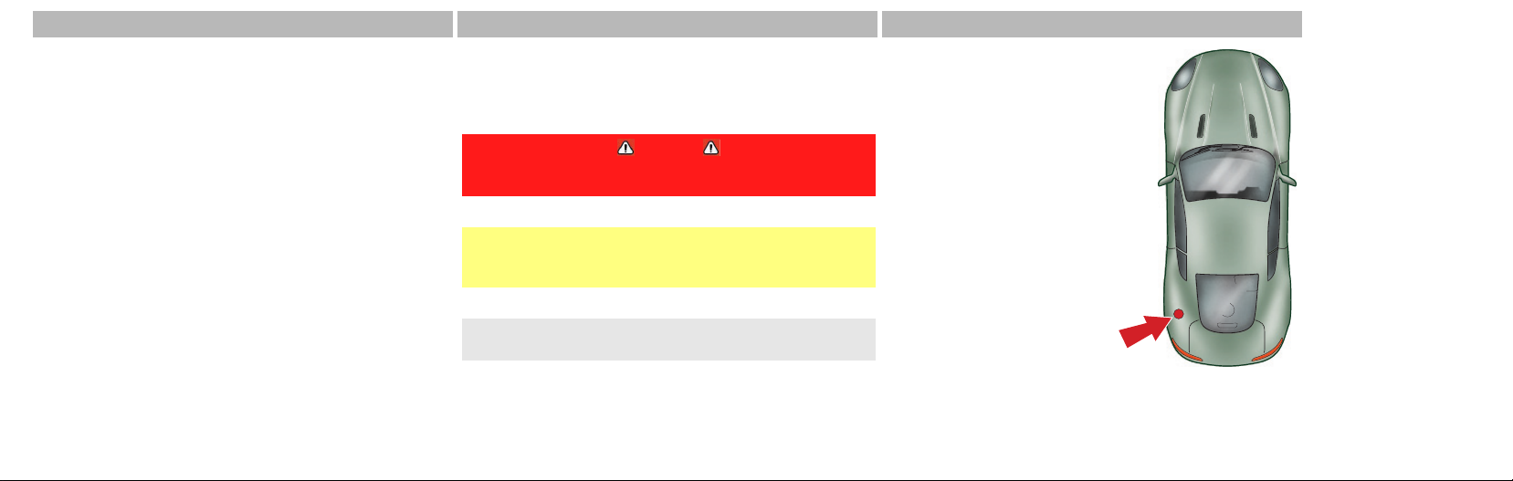
Component Location
All directions for locating
components are described as
viewed from the driver’s seat,
i.e. the fuel filler cap
indicated on this diagram will
be described as ‘located at
the rear left side of the
vehicle’.
Page 5

Vehicle Identification
The Vehicle Identification Number (VIN) is shown in the left
hand corner of the windscreen.
The Vehicle Identification Plate, attached to the front
subframe behind the engine bay front cross member (viewed
from above), is model and market dependant:
The vehicle identification
number is also stamped into
the floorpan in the RH side
footwell.
To view the vehicle identification number stamped into the
floorpan lift the carpet up, from the front, and then lift the
sound deadening material.
Data Recording
Computers in your vehicle are capable of recording detailed
data, potentially including but not limited to information
such as:
• The use of restraint systems including seat belts by the
driver and passengers
• Information about the performance of various systems and
modules in the vehicle
• Information related to engine, throttle, steering, brake or
other system status
Any of this information could potentially include information
regarding how the driver operates the vehicle, potentially
including but not limited to information regarding vehicle
speed, brake, throttle application or steering input. This
information may be stored under regular operation, in a
crash or near crash event.
1.5
Introduction
Page 6

This information may be read out and used by:
•AstonMartin
• Service and repair facilities
• Law enforcement or government agencies
Introduction
• Others who may assert a right or obtain your consent to
know such information
1.6
Reporting Safety Defects
If you believe that your vehicle has a safety defect which
could cause a crash or could cause injury or death, you
should immediately inform your Aston Martin Dealer or the
manufacturers Service Operations Department at the
address shown.
Aston Martin Lagonda Limited
Service Operations Department
Banbury Road
Gaydon
WARWICK
CV35 0DB
England
Telephone:
(International) ++44 1926 644700
(United Kingdom) 01926 644700
Facsimile (++44) 1926 644733
Vehicle Provenance
Model
e.g. Manual, Automatic
Colour
Body
Exterior
Vehicle
Identification
Number
As on the VIN plate
Interior Trim/
Piping
Interior
Veneers
Page 7

First Owner
Third Owner
Fifth Owner
Selling Dealer
Delivery Date
Second Owner
Selling Dealer
Delivery Date
Selling Dealer
Delivery Date
Fourth Owner
Selling Dealer
Delivery Date
Selling Dealer
Delivery Date
Sixth Owner
Selling Dealer
Delivery Date
Introduction
1.7
Page 8
Introduction
1.8
Page 9

Introduction................................................................... 2.2
Tracker System (Mainland UK only)................................ 2.2
Vehicle Key and Remote Transmitter.............................. 2.3
Unlocking the Vehicle.................................................... 2.4
Locking the Vehicle........................................................ 2.5
Master Lock Switch ........................................................ 2.6
Opening the Doors ........................................................ 2.7
Fuel Flap Release ........................................................... 2.7
Boot Open / Close / Lock ............................................... 2.7
Boot Emergency Release ................................................ 2.9
Deadlocking................................................................... 2.9
Drive-Away Locking....................................................... 2.9
Vehicle Security
Contents
Approach Lighting........................................................ 2.10
Homesafe .................................................................... 2.10
Alarm Cycle ................................................................. 2.10
Panic Alarm (Where enabled)....................................... 2.11
Alarm Options.............................................................. 2.11
Reduced Guard............................................................ 2.12
Remote Transmitter...................................................... 2.12
Passive Anti-Theft System (PATS) .................................. 2.13
Personalisation ............................................................. 2.14
Page 10

Introduction
Japanese Market
No vehicle alarm is installed.
Follow lock and unlock procedures as detailed, but
disregard references to vehicle alarm system.
This vehicle is protected by an electronic security system.
Vehicle Security
Two levels of alarm system are available:
•Standard
• High Specification (option) – includes an interior
movement sensor and a tilt sensor
Vehicle protection is enhanced by a passive anti-theft system
(PATS) which provides engine immobilisation if the wrong
ignition key is used.
2.2
The total vehicle security system includes:
• Remote arming and disarming
• Perimeter sensing
• Remote door, boot, fuel flap release lock and unlock
• A guard reduction mode
• Panic alarm
• Alarm siren with battery backup (in markets where audible
sirens are permitted)
• Random code encryption to prevent electronic scanning or
grabbing of the ignition key fob identity code
• Interior movement sensor (High spec alarm system only)
• Tilt Sensor (High spec alarm system only)
• Passive anti-theft system (PATS) (Engine immobilisation)
With the vehicle armed, any attempt to forcibly open a door,
the boot or the bonnet will result in full alarm activation.
Tracker System (Mainland UK only)
The Tracker hardware is installed as standard to UK vehicles
only and may be activated for any owners who wish to
subscribe to this additional vehicle security system. Please
consult your Aston Martin Dealer for Tracker details and
subscription rates.
The Tracker system places extra demands on vehicle
power while active. This will reduce vehicle battery
stand-by time (Refer to ’Battery Charge’, page 12.21).
Page 11
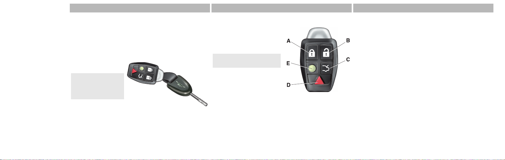
Vehicle Key and Remote Transmitter
The vehicle is supplied with three keys and two remote
transmitters. The keys operate the ignition and the door lock,
the remote transmitter operates the central locking and alarm
systems.
Keep the ‘spare’ keys and a remote transmitter together and
in a safe place.
Do not leave them in
the vehicle.
If a key or a remote
transmitter is lost,
contact your
Aston Martin Dealer.
Remote Transmitter
(A) Lock – One step vehicle
locking and alarm enable
(Refer to ’Locking the Vehicle’,
page 2.5).
The vehicle will deadlock
after 25 seconds.
(B) Unlock – One step vehicle
unlocking (Refer to ’Unlocking
the Vehicle’, page 2.4).
(C) Boot Open – Press to
enable the boot catch (Refer to ’Boot Open / Close / Lock’,
page 2.7).
(D) Panic Alarm – Activates / deactivates the panic alarm
(Refer to ’Panic Alarm (Where enabled)’, page 2.11).
(E) Approach Light – Activates the front and rear side lamps
(Refer to ’Approach Lighting’, page 2.10).
Vehicle Security
2.3
Page 12

Unlocking the Vehicle
Using the Remote Transmitter
Stand within 5m (16ft) of the vehicle. Point the remote
transmitter towards the vehicle and press the button.
The direction indicators will flash twice (Refer to
Vehicle Security
’Personalisation’, page 2.14), indicating that the alarm has
been deactivated. Both vehicle doors will unlock. The boot
catch and fuel flap release switch will be enabled.
The remote transmitter can be programmed to:
a. Unlock all doors and enable the boot and fuel flap
release switches with one press of the button
b. Unlock the drivers door only with the first press of the
button and the rest of the vehicle with a second
press.
2.4
The vehicle alarm is disabled on the first press of the button.
(Refer to ’Personalisation’, page 2.14).
As the vehicle is unlocked, the interior lamps will switch on
for 5 minutes. The lamps will switch off 30 seconds after
doors are closed or when the vehicle is started.
Using the Ignition Key
Turn the ignition key towards the rear of the vehicle and
release to centrally unlock the vehicle, enable the boot and
fuel flap release switches.
If unlocking a door using the ignition key after the vehicle
was armed, the alarm will activate. To deactivate the alarm
insert the key into the ignition and turn to position ‘II’ or
press the button on the remote transmitter.
Unlocking from Inside the Vehicle
If Locked with the Remote Transmitter
If the vehicle has been locked using the remote transmitter,
deadlocking will be active (Refer to ’Deadlocking’, page
2.9).
If the reduced guard switch has been activated, one pull of a
door handle will centrally unlock the doors, a second pull of
the door handle will open that door (Refer to ’Master Lock
Switch’, page 2.6).
If the reduced guard switch was not activated before
locking the vehicle, passengers will not be able to unlock
a door from the inside (Refer to ’Reduced Guard’, page
2.12).
Page 13
If Locked with the Vehicle Key
One pull of a door handle will centrally unlock the doors, a
second pull of the door handle will open that door (Refer to
’Master Lock Switch’, page 2.6).
Locking the Vehicle
Using the Remote Transmitter
Ensure that both doors, the boot and the bonnet are closed.
Stand within 5 m (16 ft.) of the vehicle. Point the remote
transmitter towards the vehicle and press the button
once to lock the doors, disable the boot and fuel flap release
switches and set the vehicle alarm.
The vehicle will arm and deadlock after 25 seconds.
The direction indicators will flash once (Refer to
’Personalisation’, page 2.14) as the alarm is activated.
If the vehicle is locked with the boot open, the vehicle will
lock and arm but deadlocking, tilt (option) and interior
movement (option) sensors will not activate. When closing
the boot deadlocking, tilt (option) and interior movement
(option) sensors will activate and the whole vehicle will be
locked and armed.
Do not leave the vehicle keys and remote transmitter in
the boot. If the boot is closed there will be no access to
the contents of the boot.
If passengers are to remain in the vehicle after it has
been locked using the remote transmitter, the reduced
guard switch (A) must be activated before locking. This
enables passengers to open the doors from inside the
vehicle (Refer to ’Reduced Guard’, page 2.12).
Vehicle Security
2.5
Page 14

Using the Ignition Key
Turn the ignition key towards the front of the vehicle and
release to centrally lock the vehicle, disable the boot and fuel
flap release switches.
Vehicle Security
The alarm will not be activated.
Automatic Re-locking
If the vehicle is locked by remote transmitter and then
unlocked by remote transmitter but a door or the boot is not
opened within 120 seconds, then the vehicle will
automatically lock and arm again.
Passive Alarm Setting (Belgium Only)
If, after a journey, the drivers door is opened and then closed
the alarm will automatically set after 90 seconds.
2.6
Master Lock Switch
Doors, fuel flap and boot release switches may be locked /
unlocked by pressing the master lock switch.
If the vehicle is locked
using the master lock
switch, one pull of a
door handle will
centrally unlock the
doors, a second pull of
the door handle will
open that door.
In the event of a vehicle accident the doors will
automatically unlock.
The master lock switch will not operate if the vehicle has
been locked from the outside using either the vehicle key or
the remote transmitter.
Operation of the master lock switch will override ‘Drive away
locking’.
(Refer to ’Deadlocking’, page 2.9).
Page 15
Opening the Doors
Push at point
(A) and grab
the emerging
door release.
Pull the door
release to
open the door.
If ‘Drive-away’
locking is
active one pull
of the door
handle will
centrally unlock both doors and a second pull will open that
door (Refer to ’Drive-Away Locking’, page 2.9).
If the door is left open the door puddle lamp will go out after
30 seconds.
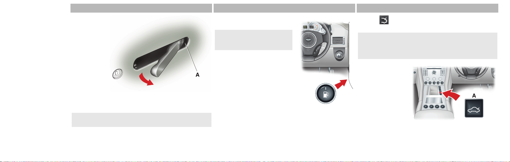
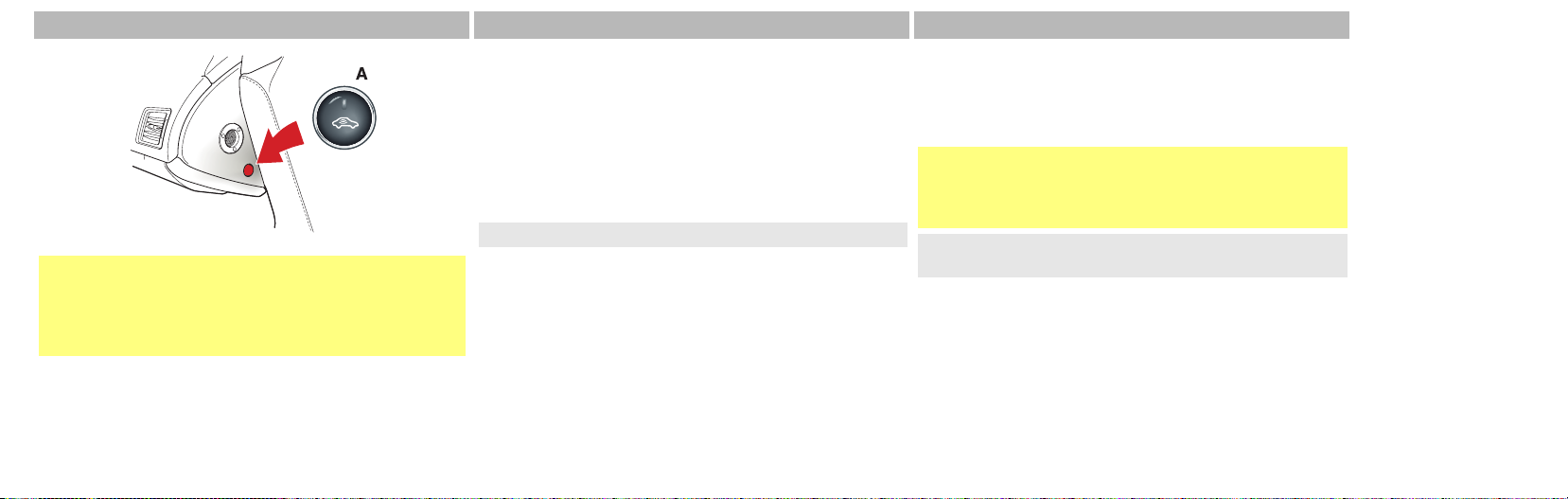
Fuel Flap Release
Push the fuel flap release switch to
open the fuel flap.
Unlock the vehicle using the
remote transmitter, to enable
the fuel flap release
The fuel flap release is disabled
when the vehicle is locked using
the remote transmitter or when the
vehicle moves off.
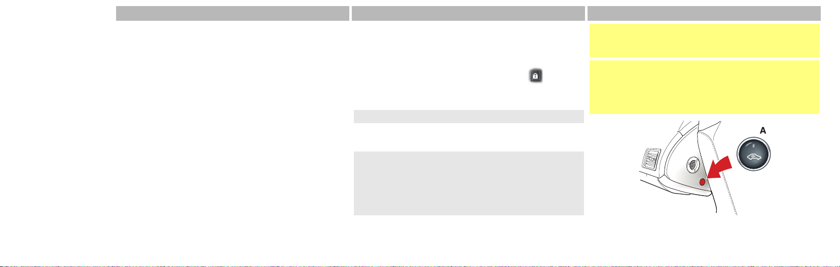
Boot Open / Close / Lock
Press the button on the remote transmitter to enable the
boot release switches.
If the vehicle is locked and armed the alarm system will be
disabled and the direction indicators will flash twice (Refer
to ’Personalisation’, page 2.14). The doors will remain
locked.
From inside the
vehicle press (A) or
operate the boot
catch (B) and lift open
the boot lid.
2.7
Vehicle Security
Page 16
To close, lower the boot lid and ensure the boot catch
engages.
The boot will not be locked.
Always ensure the boot is securely closed after use. The boot
interior lamps will remain on for 30 minutes if the boot lid
Vehicle Security
is left partially open.
2.8
Lock the boot by pressing the button on the remote
transmitter (The direction indicators will flash once (Refer to
’Personalisation’, page 2.14) as the alarm is activated).
Leaving the Boot Open While the Vehicle is Locked
To use the battery conditioner (Refer to ’Battery
Conditioner’, page 12.22) the boot has to be left open (boot
lid down but not latched).
If the vehicle is locked, with the remote transmitter, while the
boot is open, the vehicle will lock and arm (dealocking, tilt
(option) and interior movement (option) sensors will not
activate).
If the boot is then closed (latched) deadocking, tilt (option)
and interior movement (option) sensors will activate and the
whole vehicle will be locked and armed.
Do not leave the vehicle keys and remote transmitter in
the boot. If the boot is closed there will be no access to
the contents of the boot.
Page 17
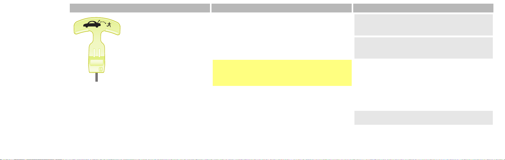
Boot Emergency Release
The boot can be opened from inside
the boot by pulling the luminous
emergency release handle.
Deadlocking
The vehicle will automatically deadlock after 25 seconds
when arming the vehicle using the remote transmitter.
When the vehicle is deadlocked, the doors cannot be
opened from the inside by pulling the interior door handle.
To open the doors activate the remote transmitter or use
vehicle key.
If passengers are to remain in the vehicle after locking
with the remote transmitter, the reduced guard switch
must be activated before locking (Refer to ’Reduced
Guard’, page 2.12).
Drive-Away Locking
All Markets Except Japanese
Drive away-locking (Auto Lock) is factory set to active (Refer
to ’Personalisation’, page 2.14).
Japanese Market
Drive away-locking (Auto Lock) is factory set to inactive
(Refer to ’Personalisation’, page 2.14).
When drive-away locking is active the central locking system
will automatically engage as the vehicle moves off. Both
doors and the boot will lock. This function prevents
unwanted access to the vehicle when stopped at traffic lights
etc.
One pull of a door handle will centrally unlock both doors, a
second pull of the door handle will open that door.
In the event of a vehicle accident the doors will
automatically unlock.
2.9
Vehicle Security
Page 18

Approach Lighting
When approaching the vehicle the side lamps can be
activated by pressing the button on the remote
transmitter.
The time that the side lamps stay on is programmable (Refer
Vehicle Security
to ’Personalisation’, page 2.14).
2.10
Homesafe
When exiting the vehicle and the ignition key has been
removed, flash the main beam (pull the LH stalk forwards
and release without latching), to active Homesafe. The main
beam and rear lamps will stay on for either 30, 60 or
90 seconds (Refer to ’Personalisation’, page 2.14).
If Homesafe has been activated with the master lamp
switch at position 3 (headlamps on), the main beam will
remain on. Ensure the master lamp switch is at position
1 before exiting (Refer to ’Master Lamp Switch’, page
4.16).
Alarm Cycle
Full Alarm Activation
A siren will sound for a 25 seconds cycle (ten cycles
maximum).
Markets where audible sirens are permitted.
The direction indicators flash for 5 minutes after which the
security system returns to the armed state.
Markets where visible alarm signals are permitted.
Doors and boot will remain locked throughout.
The alarm can be deactivated at any time during activation
by pressing the button on the remote transmitter or by
inserting the vehicle key into the ignition and turning to
position ‘II’.
Page 19

Panic Alarm (Where enabled)
Panic Alarm feature is not enabled for all markets.
This feature may be used to attract attention while inside or
outside the vehicle.
To activate the panic alarm either:
• Press the button on the remote transmitter for a
minimum of 3 seconds
• Press the button on the remote transmitter twice
within 3 seconds
When activated the vehicle horn will sound for 25 seconds
and the direction indicators will flash.
After the first three (3) seconds of activation, the panic alarm
can be deactivated by pressing the button on the
remote transmitter.
If the button is not pressed the panic alarm will cease
to sound after 25 seconds.
Alarm Options
Interior Movement Sensor
When the vehicle alarm system is activated the interior
movement sensor will sense movement inside the vehicle. If
movement is detected it will activate the vehicles alarm
system (Refer to ’Reduced Guard’, page 2.12).
Tilt Sensor
When the vehicle alarm system is activated the tilt sensor will
sense if the vehicle is tilted i.e., if the vehicle is being raised
on a jack. If vehicle tilt is detected it will activate the vehicles
alarm system (Refer to ’Reduced Guard’, page 2.12).
2.11
Vehicle Security
Page 20
Reduced Guard
Vehicle Security
If passengers are to remain in the vehicle after it has
been locked using the remote transmitter, the reduced
guard switch (A) must be activated before locking. This
will allow passengers to open the doors from inside the
vehicle.
2.12
When guard reduction is activated deadlocking, interior
movement (option) and tilt (option) sensors are disabled. This
will allow passengers to open the doors from the inside by
pulling the interior door handle and passengers or animals to
be left in the vehicle without activating the security system.
With the ignition key in the ‘0’ or ‘I’ position or within
60 seconds of removing the ignition key the reduced guard
switch can be activated.
The ignition key must have turned from position ‘II’ first.
The switch will show red when reduced guard is active.
Reduced guard remains active until the ignition key is
inserted and turned to position ‘II’.
Remote Transmitter
Battery Replacement
When the remote transmitter battery is low the warning
‘Remote Battery Low Voltage’ will show in the message
centre right.
Do not press the operating buttons during battery
replacement. If the coding is disrupted, it will be
necessary to have your Aston Martin Dealer
re-programme the remote transmitter.
Take care not to damage upper electrical contacts in battery
compartment.
Battery type: CR2032 three volt battery x1.
Page 21

1. Remove the small grub screw and withdraw the key
holder.
2. Remove a second grub screw and then part the two
halves of the battery case.
3. Replace the battery (+ve side down).
Finger marks will reduce battery life. Avoid touching the flat
surfaces of the battery and wipe the battery clean before
installation.
4. Reassemble the remote transmitter.
5. Test the alarm system ‘arm’
and ‘disarm’, using the remote
transmitter from a range of
approximately 5 m (16 ft.).
Passive Anti-Theft System (PATS)
PATS is a fully automatic engine immobiliser.
In the event of loss of one of the ignition keys, duplicate
ignition keys can be created and programmed from the
other ignition key by your Aston Martin Dealer.
Two coded ignition keys are
provided with the vehicle. These
ignition keys fit both the door locks
and the ignition lock.
To ensure a trouble-free signal
exchange between the ignition key
and the vehicle, do not cover the
ignition key head with any metal object (e.g. metal ignition
key tags or another ignition key).
Starting the Engine
When the alarm system is disarmed and the vehicle ignition
key is turned in the ignition lock, the PATS controller sends a
signal to the ignition key. The ignition key must respond with
a valid ignition key code before engine start will be enabled.
If a valid code is received, the ignition system will operate
normally.
If the ignition key code is not received, or is invalid, engine
start remains disabled.
2.13
Vehicle Security
Page 22
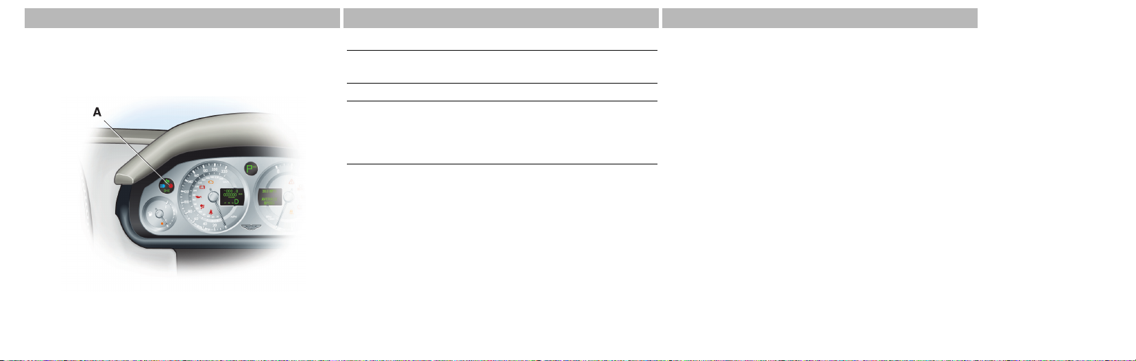
PATS Status
The PATS system state is shown by the red lamp on the
instrument cluster (A).
Vehicle Security
2.14
Ignition Action (Valid code)
Ignition turned ‘On’ Lamp illuminates for three
seconds.
Ignition turned ‘Off’ Lamp will flash.
Ignition turned ‘Off’ and
ignition key removed.
Fault Mode
If the status lamp continues flashing when the ignition is
turned on, the vehicle will remain immobilised.
Should this situation arise try turning the ignition off then on.
If this is unsuccessful try the other ignition key. If successful,
source a replacement for the faulty ignition key. If problems
persist with both ignition keys, consult your Aston Martin
Dealer.
Lamp will flash periodically for
five minutes or until the
vehicle is locked using the
remote transmitter.
Personalisation
A number of remote transmitter functions can be
personalised.
The functions are set by using the Infotainment screen.
(1) Enter – Select in the menu, activate a selection.
(2) On / Off – Infotainment centre On / Off
(3) Menu – Opens the main menu.
(4) Exit – Scroll back in the menu, cancel a selection.
(5) Screen – Presents options, menus and information.
(6) Menu Navigation – Scroll up or down in the menus
(7) Menu Navigation – Alternative method for scrolling
through the menus. Turn left or right to scroll up / down in
the menus.
Page 23

With the ignition at position ‘II’ and the Infotainment centre
on, press Menu. Select Car Settings...
From Car Settings... scroll to the required setting. Press Enter.
Use the Scroll buttons to make a selection and press Enter
to accept.
2.15
Vehicle Security
Page 24

Menu
1. Car Settings...
1.1 Lock confirm. light (*On / Off)
1.2 Unlock confirm. light (*On / Off)
Vehicle Security
1.3 Doors auto lock (On / *Off)
1.4 Doors unlock...
• **All doors / Driver door, then all
1.5 Approach light duration...
• *30 / 60 / 90 seconds
1.6 Homesafe light duration...
• *30 / 60 / 90 seconds
1.7 Information...
• VIN number...
* Default setting
** Market area dependant
2.16
Page 25

Checks Before Driving.................................................... 3.2
Seat Comfort Control ..................................................... 3.2
Steering Wheel .............................................................. 3.3
Mirrors........................................................................... 3.4
Seat Belts ....................................................................... 3.5
Child Seats..................................................................... 3.8
Airbags......................................................................... 3.10
Deployable Rollbars (Volante) ...................................... 3.13
Before Driving
Contents
Interior Storage ............................................................ 3.14
Accessory Socket.......................................................... 3.14
Ashtray and Cigar Lighter (Option)................................ 3.15
Electric Windows ......................................................... 3.16
Reading Lamps............................................................. 3.16
Page 26
Checks Before Driving
Inspect your vehicle to make sure that everything is according
to the information and specifications in this Owner’s Guide.
Outside the vehicle:
• Visually check the road wheels, nuts and tyres
Before Driving
• Check that all windows, mirrors and lamps are clear and
unobstructed
• Check that the boot, bonnet and fuel filler flap are securely
closed
• Check the operation of all lamps
Once you are in the vehicle:
• Check that the doors are securely closed
• Check that the seat, mirrors and steering wheel
adjustments are correct
3.2
Seat Comfort Control
• Check that all gauges and indicators are reading correctly
(Refer to ’Controls and Switches’, page 4.1)
• Check that the seat backs are in an upright position and
that the seat latch is engaged
• Check that all occupants have fastened their seat belts
Page 27
Warning
Do not attempt to adjust the seat whilst driving.
The ignition must be at position ‘II’ before the Heated seat
(option) and Lumbar support can be operated.
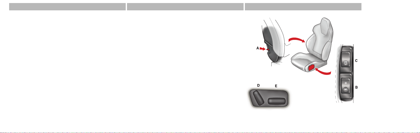
(A) Tilt – Raise the lever and tilt the seat forwards to access
the rear of the passenger compartment.
(B) Heated Seat (Option) – Press On or Off. The heater is
thermostatically controlled and maintains a constant seat
temperature until either the heater is switched off or the
ignition is switched off.
(C) Lumbar Support – Press either ‘+’ or ‘–’ to increase or
reduce lumbar support.
(D) Seat Back Angle – Increases or decreases
the angle of the seat back.
(E) Seat Base Control –
Seat forwards or rearwards.
Raise / lower the seat base.
Front. Rear.
Raise front and rear together
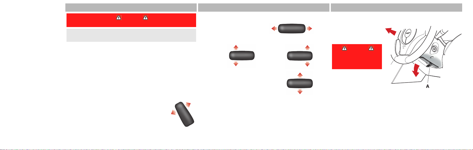
Steering Wheel
Rake and Reach
Rake and Reach are
adjusted by using the
release lever (A).
Warning
Do not adjust
steering wheel
whilst driving.
Pull the release lever
downwards and
manoeuvre the steering
wheel to the required
position. Hold the steering wheel in the required position
and lock it by pulling the release lever up.
After locking, attempt to move the steering wheel up / down
/ in / out to ensure that the lock is fully engaged.
3.3
Before Driving
Page 28
Mirrors
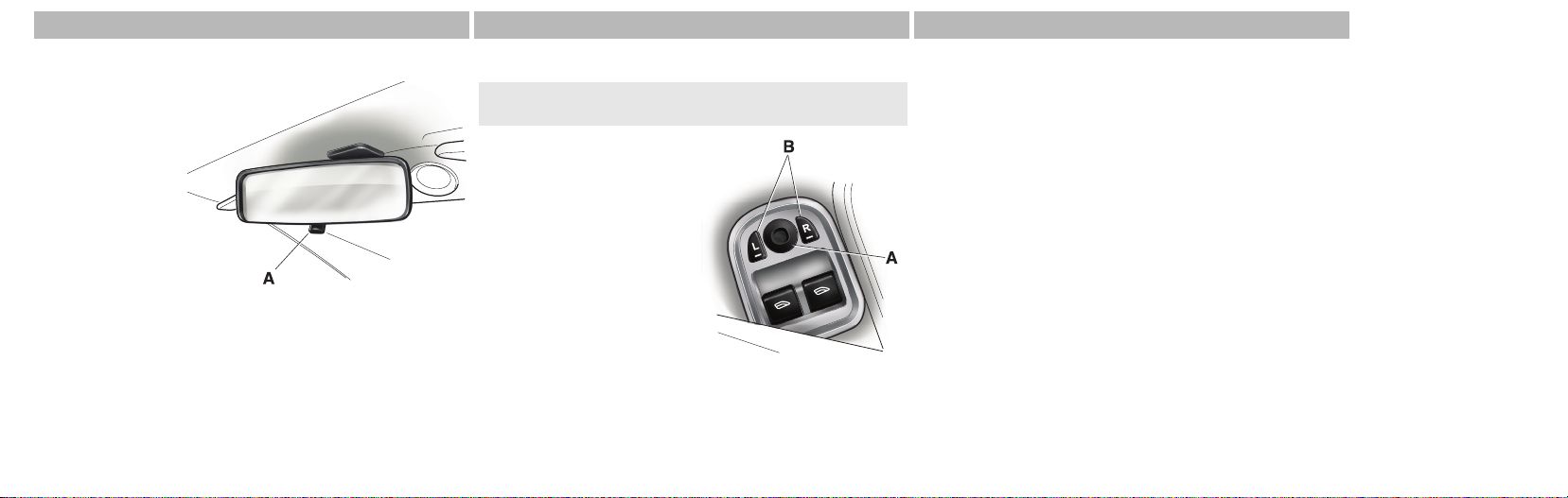
Interior Rear View Mirror
The interior rear
view mirror can be
adjusted on its ball
Before Driving
mounting until a
satisfactory rear
view is obtained.
Push the tab (A)
towards the rear to
dip the mirror. Push
the tab forwards to
re-establish the normal view.
3.4
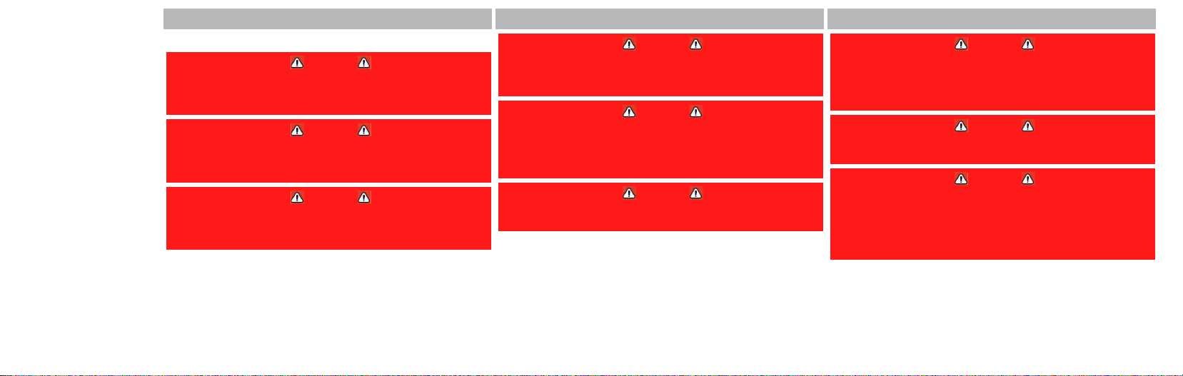
Door Mirrors
The ignition must at position ‘I’ or ‘II’ before the door
mirrors can be adjusted.
To adjust the door mirrors
select the left or right mirror
(B). Then move the joystick
(A) up / down / left / right to
adjust the selected mirror.
When the heated rear
windscreen is activated the
heaters in the door mirrors
will activate for 6.5 minutes.
Power Fold Door Mirrors (Option)
The ‘Power Fold Mirror’ function rotates the door mirror
assemblies until folded flat against the doors.
To move to the:
(1) Fold Position – Switch the ignition to position ‘I’ or ‘II’.
Press down and release the left and right hand mirror select
switches (B). The mirrors will motor to the ‘fold-in’ position.
(2) Driving Position – Switch the ignition to position ‘I’ or
‘II’. Press down and release the left and right hand mirror
select switches (B). The mirrors will motor to the driving
position.
Page 29
Seat Belts
Aston Martin strongly recommend the use of seat belts
Warning
Wearing your seat belt is crucial to your safety. Not
wearing a seat belt increases chance of serious injury or
death in the event of an accident.
Warning
Be sure that you and your passengers always fasten their
seat belts and use them properly even though airbags
are provided.
Warning
Reclining the seat back decreases protection provided
by the seat belt in the event of a crash. Adjust the seat
back to an upright position.
Warning
Make sure that the seat back is locked in place.
Otherwise it could move forward in the event of a
sudden stop or crash and cause injury.
Warning
Seat belts are designed to bear upon the bony structure
of the body, and should be worn low across the front of
the pelvis, chest and shoulders; wearing the lap section
of the belt across the abdominal area must be avoided.
Warning
Never place shoulder portion of belt under your arm or
behind your back.
Warning
Always remove from your pockets rigid or breakable
objects, i.e. spectacles or a mobile phone, which could
be trapped under seat belts, possibly causing injury in
the event of an accident.
Warning
Expectant mothers should seek medical advice on the
most appropriate way to wear the seat belt.
Warning
Seat belts must be kept clean so that the retractor works
correctly. Ensure that belt webbing is not twisted,
looped, frayed or obstructed in any way. If in doubt
about condition or operation of seat belt installation,
have it checked by your Aston Martin Dealer.
Before Driving
3.5
Page 30
Warning
No modifications or additions should be made by the
user which will either prevent seat belt adjusting
devices from operating, or prevent seat belt assembly
from being adjusted to remove slack. Never install
Before Driving
accessories on your seat belts.
This vehicle is installed with four inertia reel seat belts. The
inertia belt reels will automatically tension the belts to
provide security with comfort. In the event of a collision or
during severe braking, the belt reels will lock.
A lamp on the instrument panel will illuminate for
6 seconds when the ignition is at position ‘II’ if the
driver’s seat belt is not fastened. An audible
warning will sound at the same time.
The lamp and audible warning will continue to
active at intervals until the seat belt is fastened.
3.6
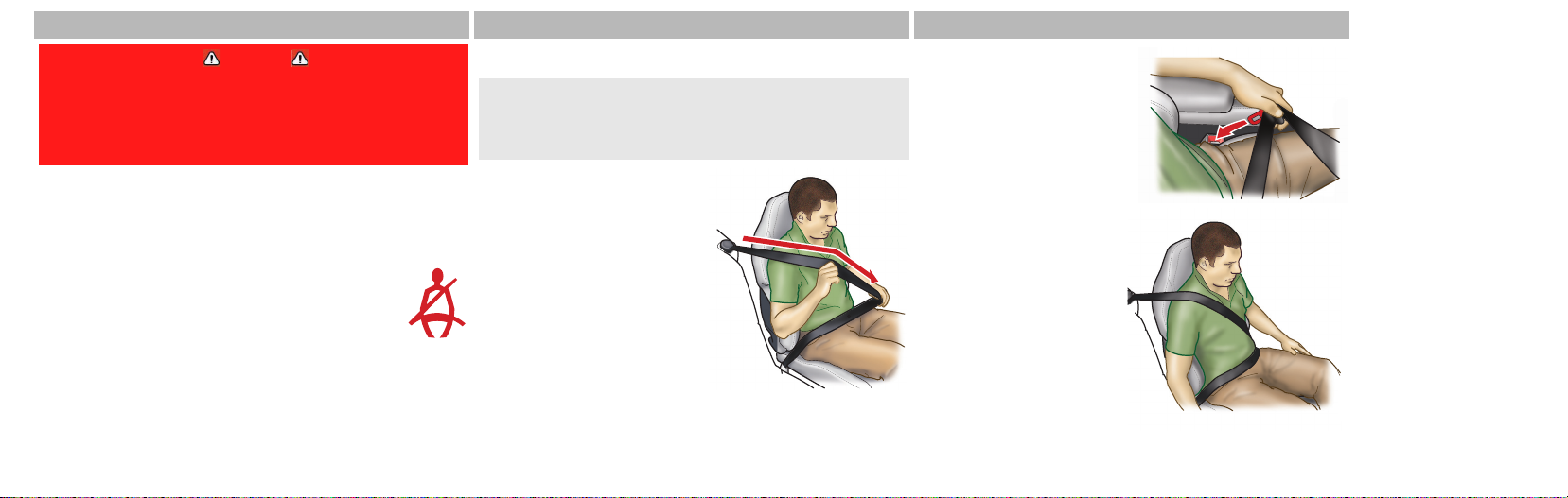
Seat Belt Fastening
When parked on an incline, the seat belt may lock as it is
withdrawn. This is not a fault. If the mechanism locks,
release the belt tension and then pull the belt very gently to
avoid operation of the inertia lock.
Pull out the seat belt, drawing
the tongue over the shoulder
and across the chest.
Push the tongue into the belt
buckle latch until a positive
click is heard.
Pull upwards on the diagonal
belt to ensure secure latching
and to remove all slack from
the belt.
Finally, double check that
the lap belt is installed
snugly, low down across the
hips, and that there are no
twists.
Page 31

If it is necessary for an occupant to adjust their seat or seating
position during a journey, the belt tension might be
disturbed. The occupant should therefore (as soon as it is safe
to do so) gently pull down the shoulder run of the seat belt to
create some slack and then immediately release it to
re-tension the belt for the new seating position.
Seat Belt Unfastening
Depress the button on the buckle.
Seat Belt Fastening (Child)
Ensure there is no slack in the webbing
and the restraint fits the child snugly
across the rib cage and hips. These are
the parts of the body most able to take
the force of impact.
The lap strap should pass across the top of the child’s thighs,
bearing on the pelvis, not on the abdominal area.
Child Safety
A child, regardless of age, should always be restrained when
travelling in a vehicle.
Warning
Do not allow children to travel in a vehicle without
restraint. An appropriate child seat or harness should
always be used.
Warning
Each seat belt assembly must be used by only one
occupant. It is dangerous to put a seat belt around a
child being carried on the occupants lap.
Warning
Accident statistics show that children are generally safer
when properly restrained in the rear seat than in the
front seat. A suitable child restraint, properly installed
and used, provides the highest degree of protection for
infants and small children in most accident situations.
Warning
Never use a rearward facing child seat in this vehicle.
Aston Martin strongly recommend not to place any child
seat in this vehicle.
Before Driving
3.7
Page 32

Pre-tensioner and Load Limiting Systems
For optimum protection, the driver and front passenger seat
belts are equipped with pre-tensioner and load limiting
systems.
Before Driving
In most moderate frontal or near frontal accidents, the front
airbag and pre-tensioner systems will deploy simultaneously.
In some moderate frontal or near frontal accidents, only the
pre-tensioner system will deploy.
The pre-tensioners take up slack in the front seat belts as the
airbags are expanding. The load limiting system releases belt
webbing in a controlled manner to reduce belt force on the
occupant’s chest.
3.8
Child Seats
Warning
Aston Martin has not tested any child restraint systems
for this vehicle, and does not recommend any specific
child restraint system.
Use of Child Seats in the European Community
The following table is supplied under EC Directive 77/541.
Mass Group (as indicated on the
child safety seat packaging)
‘0’
‘0+’
‘1’
‘11 &
Up to 10kg (0-9 months)
Up to 13kg
(0-18 months)
9 to 18kg (9 months to
4years
15 to 36kg (4 to 12 years)
111’
Seating Position
Front
Passenger
Second Row
Outboard
XX
XX
XX
XX
Key
U – Suitable for “universal” category restraints approved for this
mass group.
X – Seat position not suitable for children in the mass group.
* – Unsuitable for use with many child restraints due to limited
space.
Consult with local manufacturers of smaller forward facing
restraint and booster cushions. These manufacturers can
supply you with advice on the safety of their particular child
restraints, the position that they recommend, and also advice
on fitting instructions.
Page 33

Warning
Do not seat a child aged 12 or younger, or weighing
36 kg (79.4 lb.) or less in the car without an appropriate
child seat or booster cushion. Please confirm that any
child seat or booster cushion you may fit in the vehicle
has been designed for use in this model, and that it
conforms to local market requirements.
Use of Child Safety Seats
An infant or child that is not properly restrained can be
seriously injured or killed in a crash. Seat belts are designed
for adults and larger children; infants and smaller children
must be restrained in an approved child safety seat.
Children could be endangered in a crash if their child
restraints are not properly secured in the vehicle.
If you choose to use a child safety seat, follow the
manufacturers instructions. Never hold a baby or child on
your lap while riding in the vehicle. Check the seat
manufacturers instructions for proper use and installation –
use the correct size seat and properly secure the seat in the
vehicle in accordance with the manufacturers instructions.
Be sure to read and follow the ‘Installation and Use
Instructions’ provided with the child seat.
Child Seats and Passenger Airbags
Warning
Do not install a rearward facing child seat in the front
passenger seat position.
Aston Martin strongly recommend not to place any child
seat in this vehicle.
In the event of a serious frontal or side collision the vehicle
airbag system is designed to deploy, to provide additional
protection for the front seat occupants.
If a forward facing child seat is to be used in the front
passenger seat, follow the child seat manufacturer’s
instructions to secure the child seat and move the passenger
seat to its rearmost position.
Automatic Locking Retractors (ALR)
This vehicle has Automatic Locking Retractor (ALR) seat belts
installed to the front passenger seat and the rear seats.
This system is designed to securely hold child seats. The ALR
system temporarily locks the seat belt that is securing a child
seat.
3.9
Before Driving
Page 34

Securing a Child Seat
Install the child seat following the manufacturers instructions.
Gently pull out the relevant inertia reel seat belt until fully
extended. The ALR system will only engage at the maximum
extension point of the seat belt.
Before Driving
Thread the belt tongue through the child seat as instructed by
the child seat manufacturer. Engage the tongue into the belt
buckle.
Adjust the tongue position on the belt if necessary to ensure
that the lower belt run is tight and then allow the upper run
of the seat belt to fully retract until the child seat is securely
held. The ALR system will be heard ‘clicking’ as the seat belt
retracts. When fully retracted, pull down on the upper run of
the belt to check that the ALR lock has engaged.
3.10
Child Seat Removal
To remove the child seat, release the belt as normal and
allow it to retract through the seat frame.
When parked on an incline, the belt may lock as it is
withdrawn. This is not a fault. If the mechanism locks,
release the belt tension and then pull the belt very gently to
avoid operation of the inertia lock.
The ALR system will disengage when the belt is fully
retracted. The belt may then be worn when required as a
normal inertia reel belt. Once the ALR is disengaged, the belt
must be fully extended to re-engage the system on the next
occasion that a child seat is installed.
Airbags
The vehicle is equipped with driver and passenger airbags.
The airbags and seat belt pretensioners (Refer to
’Pre-tensioner and Load Limiting Systems’, page 3.8) are
electrically controlled by an advanced restraints system.
The front airbags (A) only deploy in a serious front collision.
The side airbags (B (one airbag in each front seat)) only
deploy according to which side has been impacted in a
serious side collision.
The purpose of the driver and passenger airbags is to provide
additional protection for the front seat occupants in the
event of a serious impact (front or side impacts). The airbags
are supplementary to the seat belts.
Important airbag safety labels are located on the sun visors
and on the end of the instrument panel (passenger side).
Ensure that the instructions on these labels are read and
complied with prior to driving the vehicle.
Page 35

Dual inflation technology
When activated, the airbags will deploy at either a normal or
reduced level of inflation, depending on crash severity.
Various sensors determine the direction and severity of an
impact. The system analyses this information then deploys
the appropriate airbags only e.g., the side airbags where the
impact is on that side only.
Airbag Deployment
Airbags inflate rapidly and with considerable force, there is
therefore a risk of death or serious injury such as fractures,
facial and eye injuries or internal injuries, particularly to
occupants who are not properly restrained by seat belts or
are not sitting correctly when the airbags deploy. The risk of
injury from a deploying airbag is greatest close to the trim
covering the airbag.
3.11
Before Driving
Page 36

The whole sequence of events from sensing the impact to full
inflation of the airbag takes place in a fraction of a second.
The noise and gas associated with the deployment of the
airbags is not injurious to health.
Before Driving
Warning
Do not use accessory seat covers. The use of accessory
seat covers may prevent the deployment of the side
airbags and increase the risk of injury in an accident.
Warning
All occupants, including the driver, should always wear
seat belts, whether or not an airbag is provided, to
decrease the risk of injury or death in the event of a
crash.
3.12
Warning
No objects whatsoever should be attached to the centre
cover of the steering wheel or the passenger fascia
panel. Such objects could cause harm if the vehicle is in
a collision severe enough to cause the airbags to deploy.
Do not change, modify or tamper with the steering wheel,
passenger side fascia or any other part of the airbag system.
Such actions could disable the system or cause inadvertent
airbag deployment.
The system will not deploy in the event of minor frontal or
side impacts, such as contacts when parking. The airbag
system is not designed to protect against rear impacts.
Any work on the airbag system must only be carried out by
an Aston Martin Dealer.
Child Seats and Passenger Airbags
Warning
Do not install a rearward facing child seat in the front
passenger seat position.
Aston Martin strongly recommend not to place any child
seat in this vehicle.
In the event of a serious frontal or side collision the vehicle
airbag system is designed to deploy, to provide additional
protection for the front seat occupants.
If a forward facing child seat is to be used in the front
passenger seat, follow the child seat manufacturer’s
instructions to secure the child seat and move the passenger
seat to its rearmost position.
Page 37

Deployable Rollbars (Volante)
Warning
Do not place any objects on the top of the deployable
rollbar covers behind the rear seat backs.
Warning
Do not allow any person to sit on the deployable rollbar
covers at any time.
Warning
Do not attempt to service or modify the deployable
rollbar system.
Warning
Do not attempt to reset the deployable rollbar system if
it deploys.
Warning
If the roof is not stowed and the deployable rollbars
deploy they will break through the rear glass.
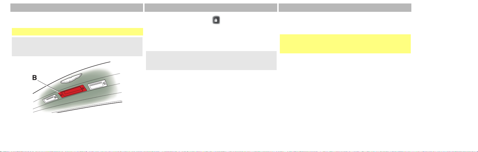
Warning Labels
The following warning labels are located on the deployable
rollbar system,
A – ‘Rollbar’
B – ‘Do Not Cover’
The deployable rollbar system
comprises an electronic roll
sensor unit mounted to the
body and two ‘U’ shaped roll
bars, concealed behind the
rear seat.
(Refer to ’Deployable Rollbars’, page 6.8)
If the deployable rollbar system has been deployed, proceed
to your nearest Aston Martin Dealer to check for any damage
and to reset the system.
Before Driving
3.13
Page 38

Interior Storage
a. Glovebox.
b. Door storage pockets.
c. Trinket box (Non smoking
option). Lift the lid to
Before Driving
open. To close the tray,
push in until it latches.
d. Trinket box and
coin / credit card
holder (Automatic
transmission).
3.14
Accessory Socket
Warning
Damage to electrical circuits will result if more than
15 amps is drawn from the accessory socket. Only
connect accessories which are designed for use in a
motor vehicle.
Warning
Prolonged use of accessory socket when vehicle is
stationary may seriously discharge battery.
An accessory socket is mounted in the
boot RH side wall and may be used to
power any 12 volt vehicle accessory
requiring a current of less than
15 amps. The boot mounted
accessory socket is a constant live.
Page 39

Read the manufacturer’s instructions and
ensure that you do not connect any device
which would exceed current rating of
accessory socket.
Ashtray and Cigar Lighter (Option)
The cigar lighter
may be used
when the
ignition switch
is in positions ‘I’
or ‘II’.
Push down
until it clicks. The lighter will pop up when ready for use.
Warning
The cigar lighter is heated to “Red Heat” when in use.
Take care to avoid burns. Do not allow children to play
with the cigar lighter.
Remove the ashtray
by opening the lid
and pulling the glass
tray upwards. Install
the tray by placing it
into position and
push down.
Before Driving
3.15
Page 40

Electric Windows
Warning
Misuse of the window switches, especially by children,
can result in injury due to entrapment in the window
closure. Drivers must advise all occupants of the
possible danger and ensure that all obstructions are
Before Driving
To raise and lower the
windows the ignition must
be at position ‘II’.
Raise – Lightly pull back and
release the window switch
(A) to raise the window in
stages.
3.16
clear before raising the window.
Lower – Lightly press and release the window switch (A) to
lower the window in stages. Press firmly and release to lower
the window with one touch.
If power to the electric windows has been interrupted for any
reason, they will fail to operate correctly until reset (Refer to
’Door Window Reset’, page 12.36).
Door Sealing
Warning
Ensure that all occupants are clear when the window
mechanism is operating.
To minimise wind noise and ensure a watertight window seal
a door sealing system is used to ensure a tight fit of the door
glass to the seals around the top of the door opening.
When a door is opened, the window glass automatically
lowers a few millimetres to clear the door seal. As the door is
closed, the window glass automatically, after a pause, raises
against the body frame rubber seals.
Reading Lamps
Both reading lamps are
controlled by the
individual switches
mounted on the
infotainment centre (A).
Unless switched off / on
at (A) they will continue
to operate up to four
minutes after the
ignition is switched off.
Page 41

Switches and Controls L/H ............................................. 4.2
Switches and Controls R/H............................................. 4.3
Instrument Cluster.......................................................... 4.4
Information / Warning Lamps......................................... 4.6
Stalk Controls............................................................... 4.10
Centre Stack (Automatic Transmission) ......................... 4.12
Centre Stack (Manual Transmission) ............................. 4.12
Centre Console (Automatic Transmission)..................... 4.14
Centre Console (Manual Transmission)......................... 4.14
Fuel Flap Switch........................................................... 4.15
Reduced Guard Switch ................................................ 4.16
Controls and Switches
Contents
Master Lamp Switch..................................................... 4.16
Vehicle Horn................................................................ 4.17
Ignition Lock ................................................................ 4.17
Trip Computer ............................................................. 4.18
Cruise Control (Option)................................................ 4.19
Ambient Temperature .................................................. 4.21
Tyre Pressure Sensing (Option) ..................................... 4.22
Page 42

Switches and Controls L/H
Controls and Switches
4.2
1. Reduced guard Switch (Refer to page 4.16).
2. Fuel flap release (Refer to page 4.16)
3. Master light Switch (Refer to page 4.16).
4. Instrument Cluster (Refer to page 4.4).
5. Centre Stack (Refer to page 4.12).
6. Centre Console (Refer to page 4.14).
7. Glovebox switch (Refer to page 4.12).
(Automatic Transmission shown)
Page 43

Switches and Controls R/H
1. Glovebox switch (Refer to page 4.12).
2. Centre Console (Refer to page 4.13).
3. Centre Stack (Refer to page 4.12).
4. Instrument Cluster (Refer to page 4.4).
5. Master lamp Switch (Refer to page 4.16).
6. Fuel flap release (Refer to page 4.16).
7. Reduced guard Switch (Refer to page 4.16).
(Automatic Transmission shown)
Controls and Switches
4.3
Page 44

Instrument Cluster
Controls and Switches
(3) Message Display (Left) – Displays the following:
(A) Trip Meter – Shows distances travelled since last reset
of trip counters T1 and T2 (Refer to ’Trip Meter’, page
4.19).
(B) Sport Mode Status (Auto Only) – Shows ‘Sport’ when
sport mode is activated.
(C) Gear Range (Auto
Only) – Indicates transmission
position and current gear
selection. Possible
transmission positions and
gear selection are in bold.
Items not in bold are not selectable.
(1) Fuel Gauge – Indicates how much fuel is in the fuel
tank. Refuel as soon as possible when the low fuel lamp
illuminates.
4.4
(2) Speedometer – Indicates vehicle road speed.
Page 45

(D) Cruise Status (Option) – Shows ‘Cruise’ when cruise
control is activated (Refer to ’Cruise Control (Option)’,
page 4.19).
(E) Odometer – Shows the total distance covered by the
vehicle.
(4) Gear Position Indicator Display (GPID) –
In Drive Auto mode indicates the current
transmission position. In ‘Touchtronic’ mode
indicates the current gear selection.
The current transmission mode is also shown
(‘Auto’ / ‘Touch’) (Refer to ’Automatic Transmission’, page
5.2).
Manual Transmission – Indicates the
optimum time to shift gear. A red ‘R’ will show
when the transmission is in reverse (Refer to
’Manual Transmission’, page 5.8).
(5) Message Display (Right) – Displays the following:
Driver Information / Warnings Messages appear if an
unsatisfactory condition is detected. Message priority is
indicated by a red / amber triangle above the message
display.
• Red Potential personal danger or danger of damage to
the vehicle
• Amber Advisory, indicate possible degraded vehicle
performance
Warning messages will be displayed when the ignition is
on and will cycle automatically. View / acknowledge
messages at any time by pressing the Read button (located
on the Infotainment Centre).
Trip Computer The message display defaults to the trip
computer when there are no messages to show (Refer to
’Trip Computer’, page 4.18).
Service Intervals
‘Time for Regular Service’ will be displayed when a regular
vehicle service is due. This message will show at ignition on
for 120 seconds. It will continue display at ignition on until
the regular service has taken place.
(6) Tachometer – Indicates engine speed in revolutions
per minute x 1000.
(7) Engine Coolant Temperature Gauge – Shows the
temperature of the engine coolant.
Controls and Switches
4.5
Page 46

Information / Warning Lamps
Controls and Switches
(2) Left Turn Direction Indicators (Green) –
Flashes with the indicator lamps or hazard warning
lamps (Ignition at position ‘II’).
(3) Headlamps (Blue) – Indicates the main beam of
the headlamps is in use.
(4) Side Lamps (Green) – Indicates the side lamps /
dip or main beams are illuminated.
(5) PATS Lamp – If the lamp flashes continuously at
ignition position ‘II’ the vehicle will remain
immobilised. If the lamp is on continuously at ignition
position ‘II’ the vehicle will start but PATS has gone into
‘Fail Safe’ mode (Refer to ’Passive Anti-Theft System
(PATS)’, page 2.13).
4.6
(1) Low Fuel Warning Lamp (Amber) – Illuminates
when approximately 9 litres (2 Galls) remain.
At 9 litres (2 Galls) and 5 litres (1 Galls) an audible ‘beep’
will sound and the ‘estimated distance’ message will show
(for 20 seconds) in the message centre right.
Page 47

Warning
Stop immediately if the Check Engine lamp flashes, do
not drive the vehicle. Contact your Aston Martin Dealer.
(6) Check Engine (Amber) – Steady amber indicates
a fault in the engine management system. Consult
your Aston Martin Dealer immediately. Flashing amber
indicates a major fault in the engine management system.
(7) Ignition Warning Lamp (Red) – Illuminates
when the ignition is on. Extinguishes when the
engine is started and battery charging commences.
Illuminates if battery charging fails whilst driving.
(8) Oil Pressure Warning Lamp (Red) – Illuminates
when the engine oil pressure falls below minimum.
Do not continue driving if this lamp remains illuminated.
Contact your Aston Martin Dealer immediately.
Warning
Do not drive the vehicle if the SRS warning lamp remains
on. Have the system checked by an Aston Martin Dealer.
(9) SRS (Supplementary Restraint System) (Red) –
At ignition positions ‘I’ and ‘II’ or on vehicle start up,
this lamp illuminates for a few seconds as a readiness
indicator. If it does not illuminate, or if it does not go off
after a few seconds, or if it comes on whilst driving, the
airbag self-diagnostic system has detected a fault.
Warning
Do not drive the vehicle if the seat belt warning lamp
remains on. Have the system checked by an Aston Martin
Dealer.
(10) Seat Belt Warning (Red) – This warning lamp
will illuminate and a chime will sound for six seconds
if the driver’s seat belt is not fastened when the ignition is
switched on. The chime will continue to activate at
different vehicle speeds until the seat belt is fastened.
(11) Warning Triangle – Indicates Red or Amber
depending on warning / information message
priority.
Controls and Switches
4.7
Page 48

Warning
If the Brake Warning lamp remains illuminated, after
fully releasing the handbrake do not drive the vehicle.
Have the system checked by an Aston Martin Dealer
(12) Brake Warning (Red) – At ignition position ‘II’
this lamp will illuminate when the handbrake is
applied. It will go out when the handbrake is fully
Controls and Switches
released. If the lamp remains on, after fully releasing the
handbrake, it indicates that either the brake fluid level is
low and / or that the brake pads require regular
maintenance (Refer to ’Footbrake’, page 5.9).
4.8
Warning
If the ABS Warning lamp remains illuminated, do not
drive the vehicle. Have the system checked by an
Aston Martin Dealer
(13) ABS Warning Lamp (Amber) – Indicates a
concern in the ABS control circuits. Consult your
Aston Martin Dealer immediately if this lamp remains
illuminated.
(14) Tyre Pressure (Amber) (Option) – At ignition
position ‘II’ or on vehicle start up, this lamp will
illuminate, as a readiness indicator. It will go off when the
tyres start to rotate. It will illuminate again if tyre pressure
falls below specification or there is fault with the tyre
pressure sensing system (Refer to ’Tyre Pressure Sensing
(Option)’, page 4.22).
(15) Dynamic Stability Control. – At ignition
position ‘II’ or on vehicle start up, this lamp will
illuminate, as a readiness indicator. If, while DSC is
active, the DSC symbol stays illuminated or it illuminates
whilst driving, the DSC system has detected a fault. A DSC
fault message will be displayed in the message centre
(right). Consult your Aston Martin Dealer as soon as
possible. (Refer to ’Dynamic Stability Control (DSC)’, page
5.12).
(16) Right Turn Direction Indicators (Green) –
Flashes with the indicator lamps or hazard warning
lamps (Ignition at position ‘II’).
(17) Rear Fog – Indicates if the rear fog lamps are
on.
(18) High Coolant Temp (Red) – Indicates when
engine coolant temperature exceeds 120°C.
Page 49

Warning Lamp Indications
As the ignition is switched on, the electronic control units
complete a self check to ensure correct operation. During
these checks, the information and warning lamps will
illuminate for 5 seconds and ‘System Check’ will appear on
the message display right. Under normal circumstances most
warning lamps will extinguish at the end of the individual
system check if system checks are satisfactory.
Controls and Switches
4.9
Page 50

Stalk Controls
Left Hand Stalk
Turn Signals – Up indicates a right
turn. Down indicates a left turn. Hold
against spring pressure to indicate a
lane change. Returns to the centre
position on completion of a
manoeuvre.
Controls and Switches
Main and Dipped Beam
Switching – Pull forwards and latch for
main beam. Pull forwards again and
latch to return to dipped beam. Pull
forwards and release without latching,
at any time while the ignition key is
inserted, to flash main beam on and off.
Pull forwards and release without latching, when the ignition
key is removed, to activate Homesafe (Refer to ’Homesafe’,
page 2.10).
4.10
Trip Computer – Repeated
pressing of the trip function button
cycles through the trip computer
displays. (Refer to ’Trip Computer’,
page 4.18).
Right Hand Stalk
Windscreen Wiper Control –
(1) Off.
(2) Intermittent Wipe.
(3) Normal Speed Wipe.
(4) Fast Wipe.
Demand Wipe – Pull the stalk
forwards.
The windscreen wipers will return to their park position if
the ignition is switched off or the bonnet is unlatched,
regardless of the RH stalk position.
Speed Sensitive Wipe – If the wipers are at fast wipe, when
the vehicle slows down (below 11 kmh (7 mph)) the wipers
will go to normal wipe speed.
If the wipers are at normal speed when the vehicle slows
down (below 11 kmh (7 mph)) the wipers will go to
intermittent wipe (position 2).
As soon as the vehicle speeds up (above 15 kmh (9.5 mph))
the wipers will return to their original setting.
Windscreen Wiper Delay Control –
Intermittent wipe time delay increases
/ decreases in six steps (A). Sixth
position gives the shortest delay
between wipes.
Page 51

Windscreen Washer Control –
Press for more than one second to
activate the windscreen washers.
Operation continues until the
button is released. When released
the washers stop immediately but
the wipers continue for a few strokes, ending with a pause
and then a final wipe.
If used during normal wiper operation, the wipers operate
continually irrespective of the washer operation.
Headlamp Washers – Headlamp washers will operate
automatically, once per journey (each ignition cycle), if the
windscreen washers are operated and the headlamps are on.
Controls and Switches
4.11
Page 52

Centre Stack (Automatic Transmission)
Centre Stack (Manual Transmission)
(1) Satellite Navigation Screen (Option (Not Middle East
/ Japan)) – Vehicles installed with Satellite Navigation only
(Refer to ’Satellite Navigation (Option)’, page 11.1).
(2) Engine Start – When illuminated Red,
press to start the engine (Refer to ’Starting
the Engine’, page 5.18).
Controls and Switches
4.12
(3) Transmission Control Switches – Automatic vehicles
only. (Refer to ’Automatic Transmission’, page 5.2).
Page 53

(4) Infotainment Centre – Contains the controls and
switches for Audio (Refer to ’Audio’, page 8.1), Telephone
(Refer to ’Car Phone (Option)’, page 9.1) and Satellite
Navigation (Refer to ’Satellite Navigation (Option)’, page
11.1).
The two top RH switches control the two reading lamps
(Refer to ’Reading Lamps’, page 3.16).
(5) Clock – The left button will retard
time and the right button will advance
time. Use an object with a point, e.g. a
ballpoint pen, to set the time.
(6) Glovebox – Press to open the glovebox. Push
up and latch to close
(7/8/9) Climate Control Switches – (Refer to ’Climate
Control’, page 7.1).
(10) Hazard Warning Lamps – Press to activate
the hazard warning lamps. Press again to
deactivate.
(11) Heated Rear Windscreen – Press to
activate the rear windscreen heater. Switches off
after 21 minutes if not manually switched off.
When the heated rear windscreen is activated
the door mirror heaters will work for 12 minutes, then
switch off.
(12) Rear Fog Lamps – Used in conjunction with
the dipped beam when fog is causing restricted
visibility. They must be switched off when
visibility clears to reduce glare to the drivers of
following vehicles.
Controls and Switches
4.13
Page 54

Centre Console (Automatic Transmission) Centre Console (Manual Transmission)
Controls and Switches
7
(1) Bluetooth (Option) LEDs (Not Middle East / Japan) –
Blue and green LEDs to indicate Bluetooth status (Refer to
’Bluetooth (Option)’, page 10.1).
4.14
(2) Master Vehicle Lock – Press to lock both
doors and disable the boot lock and the boot
open switch. Pull up to unlock. (Refer to ’Master
Lock Switch’, page 2.6).
(3) Boot Open – Pull up to open the boot. On
Volante models this switch becomes the roof
raise and lower switch (Refer to ’Convertible
Roof (Volante)’, page 6.1).
(4) Parking Assistance (Option) – Switch
parking assistance On / Off. Illuminates when
5
7
’Climate Control’, page 7.1).
Parking assistance is On. (Refer to ’Rear Parking
Assistance (Option)’, page 5.16)
(5) Heated Front Windscreen (Option) –
Switches off after 6.5 minutes if not manually
switched off. Will operate automatically when
auto defrost and defrost are used (Refer to
(6) Sport Mode Switch (Automatic transmission
only) – (Refer to ’Automatic Transmission’, page
5.2).
Page 55

(7) Dynamic Stability Control (DSC) – The DSC
system is always on when the ignition is switched
on. Press and hold for approx. 4 seconds to
switch Off. Press and release to switch On. (Refer
to ’Dynamic Stability Control (DSC)’, page 5.12).
Fuel Flap Switch
Press to open the fuel
flap.
Close the fuel flap by
pressing down on the flap
until the lock engages.
Filler Flap Emergency Release
If the filler flap will not open when the release switch is
pressed, open the filler flap manually. Reach through the LH
boot trim to access the manual fuel filler flap release. Pull the
lever (A) to open the filler flap.
Controls and Switches
4.15
Page 56

Reduced Guard Switch
The reduced guard switch disables the deadlock system and
allows for passengers or animals to be left in the vehicle
without activating the security system.
With the ignition key in
the ‘0’ or ‘I’ position or
within 60 seconds of
removing the ignition
Controls and Switches
key the reduced guard
switch can be activated.
The switch lamp will
show red when reduced
guard is active.
(Refer to ’Reduced Guard’, page 2.12).
4.16
Master Lamp Switch
(1) – All external lamps off.
(2) – Side lamps, rear lamps and
registration plate lamps on.
(3) – Headlamps on, in addition
to the side, rear and registration
plate lamps.
If Homesafe (Refer to ’Homesafe’, page 2.10) has been
activated with the master lamp switch at position 3
(headlamps on), the main beam will remain on. Ensure
the master lamp switch is at position 1 before exiting.
Day Time Running Lamps
(Denmark, Iceland and Norway only)
The dipped beams and side lights are permanently on.
Headlamp Levelling
The weight of items placed in the boot and passengers may
change the beam angle of the headlamps. The headlamps are
continuously monitored and automatically adjusted to
compensate.
Instrument Cluster Illumination
The level of instrument illumination can be adjusted using
the rotary control (A). Clockwise rotation increases the
brightness of the illumination.
Push the rotary control in and release to enable the control.
Push in and release to lock the control.
Page 57

Vehicle Horn
To sound the horn press
the centre pad of the
steering wheel.
Ignition Lock
(1) ‘0‘ – All
systems off,
steering lock
engaged.
(2) ‘I’ – Steering
lock released.
Auxiliaries on (e.g.
Audio).
(3) ‘II’ – Ignition
and all other
electrical systems on.
Vehicles with automatic transmission must show ‘P’ (Park)
in the message display (left) to remove the ignition key.
Preventing Unnecessary Battery Drain
Some circuits remain active when the ignition is switched off
and the ignition key remains in the ignition lock. If the key is
left in the ignition lock, unnecessary current will be drawn
from the battery.
A temporary
label is installed
on all new
vehicles to
ALWAYS REMOVE KEY
remind drivers
to remove the
ignition key whenever the ignition is switched off.
(Refer to ’Battery Charge’, page 12.21).
DO NOT
Leave Key
in Ignition
4.17
Controls and Switches
Page 58

Trip Computer
Pressing (A) for less than
3 seconds cycles through the trip
computer functions one at a
time. Trip computer information
is viewed in the message centre
right.
If an information message displays, after reading and acting
Controls and Switches
on the information provided press the ‘Read’ button to
return to the trip display.
Range – Estimated range on remaining
fuel (no reset). The minimum distance
displayed will read 20 km (15 mile).
Below this distance will show ‘---’.
4.18
A
Average Fuel – Average fuel
consumption since last reset. Press (A)
for more than 3 seconds but less than
5 seconds to reset. Press (A) for
5 seconds or more will reset both the
average fuel consumption and average
speed. ‘Infocenter is Reset’ will be displayed in the message
centre right.
Instantaneous Fuel – Indicates the fuel
consumption over the last 3 seconds of
travel (no reset).
Average Speed – Shows the average
speed since last reset. Press (A) for more
than 3 seconds but less than 5 seconds
to reset. Press (A) for 5 seconds or more
will reset both the average speed and
average fuel consumption. ‘Infocenter is
Reset’ will be displayed in the message centre right.
Present Speed – Indicates the present
vehicle speed.
Driver aid only.
Trip computer default screen.
Blank Screen – Blank screen will show.
Page 59

Tri p M et er
Shows distances travelled since last
reset of trip meters T1 and T2.
Toggle between T1 and T2 by
pressing (B) for less than 3 seconds.
Press (B) for more than 3 seconds to
reset the trip meter on display.
Display Units
Press (C) and (D) together for
5 seconds to change the trip
computer display units.
The display will always return to
the default display units when the
ignition is switched off.
Cruise Control (Option)
Cruise control can be used to maintain a selected vehicle
speed, above 24 km/h (15 mph), without having to use the
accelerator.
(A) RES – Resume the set
speed retained in
memory.
(B) SET ‘+’ / ’–’ – Set the
speed or accelerate /
decelerate.
(C) On / Off – Switches
cruise control On / Off.
(D) CAN – Cancels cruise
control but retains the set
speed in memory.
Cruise Control On /Off
Use the ‘On / Off’ switch (C) to activate / deactivate the
cruise control option. Under certain conditions cruise control
will automatically switch off (Refer to ’Cruise Control
Automatic Switch Off’, page 4.21). When cruise control is
active ‘Cruise’ will show in the message display (left) (Refer to
’Instrument Cluster’, page 4.4).
4.19
Controls and Switches
Page 60

Setting Vehicle Speed
Warning
Only use cruise control when conditions are favourable,
for example, straight, dry, open roads with light traffic.
When travelling at the desired speed, which must be above
24 km/h (15 mph), press the ‘SET’ (+ or –) button (B). Cruise
Controls and Switches
control will engage and maintain that speed without the need
to use the accelerator pedal.
Cruise control will automatically disengage when the brake
pedal is pressed or when the vehicle speed falls below
24 km/h (15 mph).
4.20
Changing the Set Speed
There are three ways to change the set speed:
1. Accelerate or decelerate to the desired speed then press
‘SET’ (+ or –).
2. Increase or decrease the speed by pressing and holding
either SET ‘+’ or ‘–’ until the desired speed is obtained,
then release the switch.
3. Increase or decrease the speed in steps of 2 km/h
(1 mph) by briefly pressing either SET ‘+’ or ‘–’ until the
desired speed is obtained.
Resuming the Set Speed
If the vehicle is accelerated above the set speed, then the set
speed will be resumed when the accelerator pedal is
released.
If ‘CAN’ (D) is pressed, or the brake or clutch pedal is
pressed, the cruise control will disengage but the set speed
memory will be retained. Press ‘RES’ (A) and the vehicle will
return to the set speed.
Cruise control will not resume at speeds below 24 km/h
(15 mph). ‘RES’ will not operate if the ignition has been
turned off.
‘RES’ should only be used if the driver is aware of the set
speed and intends to return to it.
It is not recommended to resume set speed when a low
gear is selected as excessive engine speeds will occur.
Page 61

Cruise Control Automatic Switch Off
Cruise control will automatically switch off and clear the
memory when:
• The ignition is switched to position ‘0’
• A fault occurs. The cruise control system will switch off and
cannot be used until the fault is cleared
• The handbrake is applied
• Maximum vehicle speed is reached
Cruise control will automatically switch off but the set speed
will remain in the memory when:
• The ‘CAN’ button is pressed
• The brake pedal is pressed
• Vehicle speed falls below 24 km/h (15 mph)
• Neutral, Park or Reverse gear positions are selected
• The difference between the actual and set speed is too
great
• When the set speed is above 144 km/h (90 mph); cruise
control will disengage automatically after approximately
20 minutes
• The accelerator pedal is used to accelerate beyond the set
speed for too long a period
Ambient Temperature
The ambient temperature (outside temperature) is displayed
in the top RH corner of the Infortainment centre display.
If the vehicle has been travelling a while and then is stopped
in a shaded / enclosed area the ambient temperature may
rise, this is due to the heat from the engine bay. The ambient
temperature display will reflect the true ambient
temperature once the vehicle is moving again or the engine
bay cools down.
If required the display units can be changed from °C to °F or
°F to °C (Refer to ’Display Units’, page 7.10).
4.21
Controls and Switches
Page 62

Tyre Pressure Sensing (Option)
Warning
Tyre pressure sensing is not intended to replace driver
awareness of tyre performance or the need for
recommended weekly checks on tyre condition and
pressure.
Tyre pressure sensing monitors the vehicle tyre pressures and
feeds this information back to the driver.
Controls and Switches
Each road wheel is installed with a tyre pressure sensing
device which sends tyre pressure information to a control
unit mounted in the centre, rear wall of the boot.
Volante Only: The tyre pressure control unit is located
underneath, at the front, of the front passenger seat.
Each pressure sensing device has a colour coded collar.
Ensure the coloured collars are installed correctly, i.e. after
new tyres are installed.
4.22
Roadway Colour
Front Right
Front Left
Rear Right
Rear Left
The control unit provides a
visual warning by
illuminating the tyre
pressure warning lamp (A)
on the instrument panel if
any tyre pressure falls
below specification.
Green
Red
Blue
Yellow
Tyre pressure sensing is
also available on winter
wheels and tyres.
Warnings
Instrument
Cluster
Control module Tyre LED constant red.
Fault Tyre pressure below specification.
Action
Reduce speed to 48 km/h (30 mph). Stop in safe place as
soon as possible.
One of the coloured LEDs on the control module will
illuminate to indicate which tyre requires inflating. The
LED colour corresponds to the colour of the band below
each tyre valve cap. Inspect affected tyre. Re-inflate if
necessary. If on inspection the tyre is found to be OK,
continue at 48 km/h (30 mph) maximum. Have the
control module checked at the earliest opportunity.
Consult your Aston Martin Dealer.
Lamp constant / Message ‘Check Tyres’.
Page 63

Take care to replace caps on the correct road wheel after
re-inflating the tyre
Instrument
Lamp constant / Message ‘Check Tyres’.
Cluster
Control module Tyre LED constant amber.
Fault Tyre transmitter fault.
Action
Reduce speed to 48 km/h (30 mph). Stop in safe place as
soon as possible.
Inspect affected tyre. Re-inflate if necessary.
If on inspection the tyre is found to be OK, continue at
48 km/h (30 mph) maximum. Have the control module
checked at the earliest opportunity.
Consult your Aston Martin Dealer.
Instrument
Cluster
Lamp constant / Message ‘Tyre system
Fault’
Control module Module LED constant amber.
Fault Control module fault.
Action
Stop in safe place as soon as possible.
Check all tyres for flats. If OK, continue at 48 km/h
(30 mph) maximum.
Have the control module replaced at the earliest
opportunity. Consult your Aston Martin Dealer.
Controls and Switches
4.23
Page 64

Controls and Switches
4.24
Page 65

Driving Safety................................................................. 5.2
Automatic Transmission ................................................. 5.2
Manual Transmission...................................................... 5.8
Footbrake ...................................................................... 5.9
Anti-Lock Braking System (ABS).................................... 5.10
Handbrake................................................................... 5.11
Dynamic Stability Control (DSC)................................... 5.12
Driving
Contents
Fuel Filling ................................................................... 5.14
Rear Parking Assistance (Option) .................................. 5.16
Driving Techniques ......................................................5.17
Starting the Engine ....................................................... 5.18
Driving (Automatic Transmission) ................................. 5.18
Page 66

Driving Safety
Always wear your seat belt
• Never drive under the influence of alcohol or drugs
Driving
• Always obey all speed and traffic laws and regulations.
Never drive faster than the posted speed limit or than
conditions allow
• Be particularly careful driving on slippery or wet surfaces
• This vehicle is a high performance vehicle and has
handling characteristics you may not be accustomed to.
Familiarise yourself with the vehicle and always drive
prudently, being aware of your own limitations and the
limitations of the vehicle. As with other vehicles of this
type, failure to operate the vehicle properly can result in
accident and injury
• Follow the maintenance schedule prescribed in this guide
• Never allow the vehicle to be driven by inexperienced
drivers
5.2
Automatic Transmission
Innovative ‘Shift by Wire’ technology has allowed
Aston Martin to replace the conventional PRND shift lever
with a series of PRND selection buttons and gearshift paddles
(Touchtronic control).
PRND Buttons
P (Park)
‘P’ can be selected from any gear position once the
vehicle is stationary. The transmission will
mechanically lock.
If the ignition is turned to position ‘0’ while the
vehicle is at a standstill, the transmission will
automatically select ‘P’ (Auto park).
Always ensure that the handbrake is
applied.
The message centre left displays the current position and the
GPID displays ‘P’.
It is not possible to select ‘P’ above approx. 2 km/h (1 mph).
R (Reverse)
The engine cannot be started in this position.
Reverse can only be selected by pressing the ‘R’
button, while in ‘P’ or ‘N’, with the brake pedal
pressed.
If the vehicle speed is less than approx. 5 km/h (3 mph), ‘R’
may be selected from ‘D’, without pressing the brake pedal,
to enable a vehicle ‘rocking’ i.e. to enable vehicle movement
out of mud, snow, etc. If 5 km/h (3 mph) is exceeded then
the transmission will automatically select ‘N’.
Page 67

If the brake pedal is not pressed the message display will
read ‘Press Brake Pedal’.
The message centre left displays the current
position, the GPID displays ‘R’ coloured red,
an audible warning will sound and the reverse
button ‘telltale’ lamp will illuminate.
N (Neutral)
Select neutral by pressing the ‘N’ button or by
pulling back on both gearshift paddles
simultaneously.
When selecting ‘N’ from ‘P’ the brake pedal
must be depressed.
If the brake pedal is not pressed the message
display will read ‘Press Brake Pedal’.
The message centre left displays the current
position and the GPID displays ‘N’.
D (Drive)
The engine cannot be started in this position.
At standstill drive is selected by pressing the ‘D’
button with the brake pedal depressed.
If the vehicle speed is less than approx. 5 km/h (3 mph), ‘D’
may be selected from ‘R’, without pressing the brake pedal.
This enables a vehicle ‘rocking’ motion, i.e. to enable
vehicle movement out of mud, snow, etc.
If the brake pedal is not pressed the message display will
read ‘Press Brake Pedal’.
Driving
5.3
Page 68

The message centre (left) will display the
current position, the GPID displays ‘D’ and
Driving
‘Auto’ and the drive button ‘telltale’ lamp will
illuminate.
From ‘D’ enter ‘Touchtronic’ mode (Refer to
’Touchtronic Mode’, page 5.4) by pulling back
on either the ‘+’ or ‘–’ gearshift paddles. The message centre
left will still display the current position but the GPID will
now display the current gear, i.e. ‘2’ and ‘Touch’ and the
drive button ‘telltale’ lamp will go out.
If selecting drive from ‘N’, ‘D’ or ‘Touchtronic’ mode can
‘Touchtronic’ – Pull back the either the ‘+’ or ‘–’ gearshift
5.4
be selected.
‘D’ – press the ‘D’ button.
paddles.
Gearshift Paddles
Two gearshift paddles (A)
are mounted behind the
steering wheel. In
touchtronic mode use the
paddles to change gear.
RH paddle (+) – Controls
upshifts
LH paddle (–) – Controls
downshifts.
Touchtronic Mode
Gearshifts up and down are controlled by the driver, using
the shift paddles mounted on the steering column.
While in ‘D’ select ‘Touchtronic’ mode by pulling back on
either the ‘+’ or ‘–’ gearshift paddles. As a paddle is pulled
back a gearshift will occur, this will be an upshift or downshift
according to which shift paddle is pulled.
To select ‘Touchtronic’ mode directly from ‘N’, pull back
either the ‘+’ or ‘–’ gearshift paddles.
If no driver input is detected the transmission will
automatically upshift and downshift to remain within
operating limits of the engine and transmission (except
when in Sport mode (Refer to ’Sport Mode’, page 5.5)).
Page 69

When shifting gear the GPID displays the target
gear and ‘Touch’, while the message centre
left will display the actual gear when the
transmission has shifted.
Sport Mode
Sport mode can be selected while in
‘D’ or ‘Touchtronic’ modes. Press the ‘Sport’
button once to enter sport mode and press again to
exit sport mode.
The Sport mode button lamp will illuminate and ‘Sport’ will
display in the message centre (left) when sport mode is
engaged.
If selecting ‘Sport’ mode while in ‘D’ – top gear (6th) a
downshift to 5th gear will occur.
This will not happen if cruise control (option) is active.
Upshifts and downshifts will occur at higher engine speeds in
‘D’ Sport than in ’D’ Auto mode to provide a sportier drive.
When Sport mode is engaged while in ‘Touchtronic’ mode,
automatic upshifts are inhibited.
To inform the driver that
the current gear has
reached it’s upper rev.
limit the GPID gear
indication will change from green to flashing red.
Maximum Engine Speed
The maximum safe engine speed is 7,200 rpm. If this speed
is exceeded, fuel supply to the engine is reduced. As the
engine speed reduces back to a safe level, fuel supply is
progressively restored.
Park (P) Override
If the vehicle fails to start or has broken down the automatic
transmission will go into ‘P’ (park) mode. To tow or move the
vehicle a ‘park override’ lever is provided to manually
disengage the automatic transmission park lock.
Apply the handbrake before operating the park override.
There is the danger that the vehicle will roll, depending
on the incline of the road.
After stopping the vehicle apply the handbrake and push
back the park override lever.
5.5
Driving
Page 70

Operating the Park Override
Apply the handbrake. Remove the LH rear seat base (A) and
Driving
unscew the two screws that secure the park override lever
cover. Remove the cover.
Pull the manual park override lever (B) fully up on the
ratchet, fully releasing the parking lock.
After towing or moving the vehicle apply the handbrake. Lift
the manual park override lever slightly, press the ratchet
release (C) and lower the manual park override lever back to
the stop. The parking lock is now engaged. Install the cover
and the rear seat base.
The message in the instrument pack must disappear and
the position display must change from ‘N’ to ‘P’.
Otherwise there is the danger that the vehicle will roll
away.
5.6
Limp-home Mode
If a fault is detected in the ‘Shift by Wire’ system the vehicle
will go into ‘Limp Home’ mode. There are three types of
‘Limp Home’.
Electrical – ‘Gearbox Fault Reduced Function’ will be
displayed in the message centre right. Touchtronic and Sport
modes will be disabled. Gearshifts will still be possible but
shift quality will be degraded.
In certain circumstances ‘D’ will be restricted to 3rd gear. If
travelling at speed 3rd gear will engage when an appropriate
speed has been reached.
Contact your Aston Martin Dealer.
Reduced Engine Performance – ‘Reduced Engine Perform’
will display in the message centre right. Engine performance
will be restricted. Contact your Aston Martin Dealer.
Page 71

Mechanical – ‘Limphome No Gear Change Possible’ will
display in the message centre right and an audible warning
will sound. If travelling forwards in ‘D’ or ‘D Touch’ the
vehicle will go into a locked gear (3rd or 5th depending on
vehicle speed).
Do not attempt to change position while in mechanical
limp home mode, i.e. pressing either P, R, N, D or
pulling back on both gear shift paddles simultaneously.
If this request is detected at a speed below approx.
20 km (12.5 mph) the engine will stop and the parking
lock will engage.
At a speed above approx. 20 km (12.5 mph) the request
and any other transmission request will be rejected and
the vehicle will continue in 3rd or 5th.
If entering mechanical limp home mode in any position other
than ‘D’, ‘D Touch’ (forward gears) the park lock will engage
(Refer to ’Park (P) Override’, page 5.5). Contact your
Aston Martin Dealer.
Driving
5.7
Page 72

Manual Transmission
The manual
transmission
Driving
features a six
speed gearbox.
Gearshifts
Press the clutch
pedal, move the
gear lever to the
required gear
position then
slowly raise the clutch pedal.
Reverse gear is selected by overcoming spring resistance.
A red ‘R’ will show in the GPID when the
transmission is in reverse.
5.8
To inform the driver that the current gear has reached it’s
upper rev. limit the GPID will indicate revs increasing. The
optimum time to shift gear is when the GPID shows three
bars and is red at the top and bottom.
For the first 2000 km (1243 mile) and when ever the engine
temperature is below 40°C (104°F) the shift control will
indicate early shift changes to protect the engine.
Maximum Engine Speed
The maximum safe engine speed is 7,200 rpm. If this speed
is exceeded, fuel supply to the engine is reduced. As the
engine speed reduces back to a safe level, fuel supply is
progressively restored.
Page 73

Footbrake
The footbrake operates through a vacuum boosted, dual
(diagonal split) circuit, hydraulic system incorporating an
Anti-lock Brake System (ABS).
Vacuum boost is only available while the engine is running.
If one circuit fails brake pressure will still be available to two
road wheels. The footbrake will still operate but with greater
pedal pressure, increased pedal travel and longer stopping
distances.
Warning
In the event of a brake failure bring the vehicle to a halt
as soon as it is safe to do so. Do not continue to drive.
Brake Warnings
While driving, if the brake warning lamp illuminates, it
indicates either that:
• The handbrake is not fully released
• The brake pads require regular maintenance
• The brake fluid level has fallen below an acceptable level
A warning message will show in the message centre right.
Stop, as soon as possible in a safe and convenient place, and
ensure that the handbrake is fully released. If the handbrake
is fully released and the lamp remains on, do not drive the
vehicle. Contact the nearest Aston Martin Dealer. It is
essential that the brake system is checked immediately,
preferably by an Aston Martin Dealer.
Warning
If the brake warning lamp illuminates, you should
immediately be prepared for possible increased
stopping distances and possible partial failure of the
braking system.
Driving
5.9
Page 74

Anti-Lock Braking System (ABS)
The anti-lock braking system (ABS) helps prevent the road
wheels from locking and skidding during emergency braking.
Driving
This also assists the driver in maintaining steering and
directional stability.
If, in an emergency braking situation, the braking force
applied begins to exceed the tyre to road adhesion, the ABS
is activated to prevent the road wheels locking. When this
happens a pulsating effect is felt through the brake pedal.
This is a normal ABS effect.
Safety
In all cases it remains the drivers responsibility to drive safely
according to the law and with due regard to prevailing
conditions. The fact that a vehicle is equipped with ABS must
never allow the driver to be tempted into taking risks which
could affect his or her safety or that of other road users.
5.10
The addition of ABS cannot overcome the consequences of
trying to stop in too short a distance, cornering at too high a
speed, or the risk of aquaplaning (where the tyres are
prevented from contacting the road surface by a layer of
water).
The driver should always take road conditions into account.
A slippery road surface always requires more braking
distance for a given speed, even with ABS. Possible
extensions of stopping distance compared to locked wheels
may occur during ABS operation on slushy snow, gravel, sand
or certain heavily corrugated or ridged warning sections of
road surfaces.
If any braking system malfunction occurs, immediately have
the Braking and ABS systems checked by your Aston Martin
Dealer.
ABS Warning
Warning
If the ABS warning lamp illuminates, you should be
aware that wheels could lock during extreme braking or
when braking on slippery surfaces.
ABS is monitored for correct operation while the ignition is
switched on. If a fault is detected, the ABS warning lamp
will illuminate and the ABS will be partly or fully disabled.
Normal braking will continue to function without ABS.
In the event of an ABS fault, consult your Aston Martin
Dealer immediately.
Page 75

Handbrake
Always fully apply the handbrake before leaving the
vehicle.
To apply the handbrake:
1. Press the footbrake pedal firmly.
2. While pressing the footbrake pedal, pull the handbrake
lever up, smartly, to its fullest extent.
Do not press the release button while pulling the
handbrake lever up.
3. Allow the handbrake lever to lower.
If the ignition is on the handbrake warning light on
the instrument cluster will illuminate, indicating that
the handbrake is applied.
To release the
handbrake:
1. Press the
footbrake
pedal firmly.
2. While pressing
the footbrake
pedal, pull the
handbrake
lever up until
resistance is felt, then depress the release button and
push the handbrake lever down.
If the handbrake lever is not fully off, the handbrake warning
light will stay on.
Always check that the brake warning lamp is correctly
extinguished before moving off. Do not attempt to drive
the vehicle if the brake warning lamp remains on.
An audible warning will sound if the vehicle is moving and
the handbrake is still applied.
• If the vehicle is parked on a hill and facing uphill, select
first gear and turn the steering wheel away from the
kerb.
• If the vehicle is parked on a hill and facing downhill,
select reverse gear and turn the steering wheel towards
the kerb.
5.11
Driving
Page 76

Dynamic Stability Control (DSC)
Warning
It is the drivers responsibility to drive safely according to
Driving
the law and with due regard to prevailing conditions.
Warning
DSC must never allow the driver to be tempted into
taking risks which could affect his or her safety or that of
other road users. DSC cannot overcome consequences
of applying too much engine power for prevailing
conditions.
Dynamic Stability Control (DSC) is a system designed to
enhance driving safety by improving the vehicle handling
when the tyres are at the limits of their grip capabilities. This
is achieved through the reduction of engine torque and
strategic application of the brakes at individual wheels.
5.12
Driver Interface and Control
The DSC system is switched ‘On’ when the engine is started.
When the system is operating, the DSC warning lamp will
flash.
DSC can be switched ‘OFF’ by pressing the DSC
switch for a minimum of 4 seconds.
The DSC button lamp and the DSC symbol
(instrument pack) will illuminate
continuously when the system is switched ‘OFF’.
‘DSC FUNCTION OFF’ will be displayed in the message
centre right to indicate that DSC is ‘OFF’.
Press and release the DSC switch again to switch the DSC
‘ON’.
Use tyres of the same manufacturer, brand, tread
pattern and correct size specified for this vehicle on all
four road wheels. Do not mix worn tyres.
The DSC may not operate correctly when using tyre
chains or a temporary spare tyre.
If repair or replacement of the steering or other
surrounding equipment is necessary, always refer to
your Aston Martin Dealer. If the centre position of the
steering deviates, the DSC may not operate correctly
because there is a sensor in the steering which detects
steering wheel position.
Page 77

Fault Indication
A malfunction in the DSC control system will be indicated by
the following:
• The DSC lamp in the instrument cluster will illuminate
continuously
• A warning message will be displayed in the message centre
right depending on the fault detected
If vehicle cruise control (option) is engaged it will
automatically disengage when traction control is operating.
Tra ct i on Co nt r ol
Warning
It is the drivers responsibility to drive safely according to
the law and with due regard to prevailing conditions.
Warning
Traction Control must never allow the driver to be
tempted into taking risks which could affect his or her
safety or that of other road users.
Warning
Traction Control cannot overcome consequences of
applying too much engine power for prevailing
conditions.
Traction control is a function of DSC, and is operated in
association with the DSC system.
Traction control prevents excessive wheel-spin at standing
starts, or during acceleration. Wheel-spin is usually caused by
excessive use of the accelerator pedal, or slippery, loose or
bumpy road surfaces.
To prevent excessive wheel-spin and maintain vehicle
stability in such situations the traction control system will:
• Brake the driven-wheel when it starts to slip
• And / or adapt the engine torque to a level corresponding
to the traction available on the road surface
These symptoms are normal and will clear as wheel spin is
eliminated and normal engine power is restored.
During activation, the DSC warning lamp will flash. The
driver may experience a loss in power or temporary ’misfire’
as engine power is reduced.
5.13
Driving
Page 78

If traction control cuts in when driving on extended icy or
slippery surfaces, reduce engine power as necessary until the
Driving
DSC warning lamp is extinguished.
Do not maintain engine power at such a level that
traction control is activated for long periods (more than
about one minute). This reduces fuel to the engine and
may cause the exhaust catalysts to overheat.
Overheating of the exhaust catalysts can destroy them.
Traction control is always operational when DSC on.
5.14
Fuel Filling
Open the fuel flap by
pressing the fuel flap release
switch.
The vehicle alarm must be
off to enable the fuel flap
release switch.
Rotate the cap anticlockwise
past resistance, then lift off.
Place the cap into it’s
holder.
Install the cap by turning clockwise past resistance, until three
‘clicks’ are felt as the cap is fully tightened. Close and latch
the fuel flap.
The fuel tank filler neck has a restricted opening which will
only accommodate the fuel supply nozzle of unleaded fuel
pumps.
The fuel system will not permit overfill but there will be
instances when the nozzle will shut off prematurely. If this
happens wait 5 seconds after nozzle shut off before trying to
re-initiate fill.
Fuel Cutoff
In the event of a vehicle accident the vehicle will enter Crash
mode. Power to the fuel pumps will terminate, thereby
reducing fire risk.
Page 79

Filler Flap Emergency Release
If the filler flap will not open when the release switch is
pressed, open the filler flap manually (Refer to ’Filler Flap
Emergency Release’, page 4.15).
Catalytic Converters
Warning
Do not park over dry grass, leaves or other combustible
material. Significant fire risk exists because of residual
heat in the catalytic converters.
Warning
Do not drive through deep water. Rapid cooling of
catalysts may cause them to break up.
Catalytic convertors convert harmful exhaust gasses into less
noxious substances and so reduce environmental pollution.
They operate at high temperatures and continue to radiate a
considerable amount of heat after turning off the engine.
Leaded fuel will cause irreparable damage to catalytic
converters. If leaded fuel is inadvertently added to the fuel
tank do not start the engine, do not drive the vehicle.
Contact your Aston Martin Dealer immediately.
Driving
5.15
Page 80

Rear Parking Assistance (Option)
Warning
Rear parking assistance does not replace need for total
Driving
vigilance and caution when parking or reversing.
Rear parking assistance assists in detecting
obstructions as the vehicle is reversed towards
them. The system is active when reverse gear is
selected. When the system is operating an
intermittent ‘beep’ signal will be heard. The ‘beep’ increases
in persistence as the vehicle reverses to an obstruction.
The ‘beeps’ start at approx. 1.7 m (5.5 ft.) from any
obstruction. The ‘beep’ becomes continuous at distances
5.16
less than 30 cm (1 ft.).
If reversing into a confined area, i.e. a home garage, the rear
parking assistance outer sensors will detect the side walls
and, after 3 seconds, the ‘Beep’ sequence will stop. As
reversing continues the rear parking assistance inner sensors
will detect the rear wall / obstruction and the ‘Beep’
sequence will start again.
Press the parking assistance button to disable rear parking
assistance. The rear parking assistance button will illuminate
when the system is disabled.
When parking or reversing make full use of rearward
vision and all mirrors to be aware of persons or objects
in the vicinity of the vehicle. Take appropriate measures
to protect them from danger.
In heavy rain or similar adverse conditions, the rear
parking assistance sensors may not always be able to
accurately measure distance to close objects. A fully
laden vehicle or irregular obstacles may also cause
inaccurate measurements.
The parking sensors
should be kept clear of
dirt, snow etc. to ensure
clean signals and
accurate distance
monitoring.
Page 81

Driving Techniques
Procedures for driving this vehicle may be unfamiliar to many
new owners. Please take time to safely acquire the necessary
new driving skills. Practise in safe, lower speed conditions
before investigating the high performance potential of the
vehicle. Please ensure a safe and enjoyable entry into this
new phase of Aston Martin motoring.
High performance driving courses are available to enable
customers to get the best from their vehicle in the safest way.
Consult your Aston Martin Dealer.
Wet Conditions
When driving in wet conditions, water can build up under
your tyres so that they ride on a layer of water. This is called
aquaplaning or hydroplaning. When this happens, you have
little or no control.
This vehicle should not be driven through water depths
of up to 175 mm (7 in) above 50 km/h (30 mph) or
through water depths over 175mm (7 in) above idle
speed.
Water depths of 200 mm (8 in) or more should not be
traversed as this may cause extensive damage to the
engine.
Aquaplaning is more prone to happening at higher road
speeds if there is a lot of water on the road and particularly if
the tyres are also under inflated or approaching minimum
tread depth. Slow down when it is raining.
It is important to take bends or curves at a safe, reasonable
speed, particularly when driving on wet or slippery road
surfaces.
Running-In
This vehicle is fully hot tested during manufacture and no
special running-in procedures are necessary. Nevertheless it
is prudent to limit engine loads (e.g. by accelerating gently
and by using lower gears on steep hills or when negotiating
tight turns) during the first 4,000 km (2,500 mile).
Overspeed Warning ‘Gong’ (Middle East only)
If vehicle speed reaches 120 km/h (74.5 mph) a warning
‘gong’ will sound. This warning will continue until either the
vehicle speed goes beyond 130 km/h (81 mph) or the vehicle
speed falls below 117 km/h (73 mph).
If the vehicle speed has increased beyond 130Km/h
(81 mph) the warning ‘gong’ will not sound again until the
vehicle speed has fallen below 120 km/h (74.5 mph) and
then increased to 120km/h (74.5 mph) or greater.
5.17
Driving
Page 82

Starting the Engine
Ensure you are wearing appropriate footwear to efficiently
operate the control pedals. Ensure pedal movement is not
Driving
restricted by floor mats or other objects trapped beneath
pedals
.
1. Check that the handbrake is applied and insert the
ignition key. Rotate to position ‘II’.
Automatic Transmission: ’P’ will show on the GPID and
in the message display left. The engine start button will
illuminate red.
Under certain conditions ‘N’ may be displayed. This may
indicate a transmission fault. Consult your Aston Martin
5.18
Dealer
Manual transmission: The start button will not
illuminate red until the clutch pedal is pressed down.
‘Please press clutch to start’ will show in the message
display right.
2. Press the illuminated (red) ‘Engine Start’ button, wait until
the engine fires, then release the button.
The engine start button will show a white light when the
engine is running, and then fade out.
If the start button does not illuminate red, check that the
BDS is not active (Refer to ’Battery Charge’, page 12.21). If
the BDS is not active look for a fault message in the message
centre right. Contact your Aston Martin Dealer.
Starting From Cold
The engine management system automatically compensates
for cold or warm start conditions and makes appropriate
adjustments to the fuel / air mixture and ignition timing.
Driving (Automatic Transmission)
Automatic Mode
1. Start the engine.
2. Apply the footbrake and select a drive option. Check that
the handbrake is released. Release the footbrake and
gradually increase engine speed to move off. Gearshifts
will occur automatically as speed increases.
When selecting a gear ensure that the correct position and
gear has been selected by checking the message display left
and the GPID.
At any point while in ‘D’ pull back on a gear shift paddle to
enter ‘Touchtronic’ mode (‘+’– Upshift / ‘–’– Downshift).
3. To bring the vehicle to a halt, press the brake pedal. The
transmission will downshift automatically.
The vehicle will remain ready to move off immediately
when the accelerator is pressed.
Page 83

When the vehicle is stationary the transmission will select
1st gear.
4. To stop the engine, press ‘P’, apply the handbrake and
turn the ignition key to position ‘O’.
If unable to engage ‘P’ a warning will appear in the
message centre right and a audible warning will sound.
Touchtronic Mode
1. Start the engine.
2. Select Touchtronic mode.
•From position ‘P’
Apply the footbrake and push the ‘D’ button, then pull
back either the ‘+’ or ‘–’ gearshift paddles.
•From position ‘N’
Apply the footbrake and pull back either the ‘+’ or ‘–’
gearshift paddles.
When selecting a gear ensure that the correct position and
gear has been selected by checking the message display left
and the GPID.
3. Check that the handbrake is released. Gradually increase
engine speed to move off.
4. Upshift by pulling and releasing the ‘+’ paddle and
downshift by pulling and releasing the ‘–’ shift paddle.
Upshifts and downshifts will automatically occur if the
engine speed rises or lowers to the Max. or Min. operating
limits. Unless the transmission is in Sport mode (Refer to
’Sport Mode’, page 5.5).
At any point while in ‘Touchtronic’ mode press the ‘D’
button to enter Automatic mode.
5. To bring the vehicle to a halt, press the brake pedal and
downshift as required.
The transmission will automatically downshift if no driver
input is detected.
When the vehicle is stationary the transmission will select
1st gear.
The vehicle will remain ready to move off immediately
when the accelerator is pressed.
6. To stop the engine, press ‘P’, apply the handbrake and
turn the ignition key to position ‘O’.
If unable to engage ‘P’ a warning will appear in the
message centre right and a audible warning will sound.
5.19
Driving
Page 84

Selecting Reverse
Bring the vehicle to a halt, press the brake pedal and press
Driving
the ‘R’ button.
If the brake pedal is not pressed the message display will
read ‘Press Brake Pedal’.
While the vehicle is stationary reverse can be selected from
any gear position.
If the vehicle speed is less than approx. 5 km/h (3 mph), ‘R’
may be selected from ‘D’, without pressing the brake pedal,
to enable a vehicle ‘rocking’ motion i.e. to enable vehicle
movement out of mud, snow, etc.
Reverse can not be selected over approx. 5 km/h (3 mph).
5.20
The button lamp will illuminate red and ‘R’ will be displayed,
in red, in the GPID. Additionally, an audible warning will
sound.
Release the brake pedal. Press the accelerator to move off in
reverse.
Deselection of Reverse
Bring the vehicle to a halt. Either select a new gear position
from the PRND buttons or pull back on both shift paddles to
select ‘N’.
Page 85

Roof Operation.............................................................. 6.2
Raising the Roof ............................................................. 6.3
Lowering the Roof.......................................................... 6.4
Manual Operation ......................................................... 6.5
Convertible Roof (Volante)
Contents
Roof Maintenance.......................................................... 6.7
Deployable Rollbars ....................................................... 6.8
Page 86

Roof Operation
Aston Martin recommend that the convertible roof is
not operated at temperatures of 0°C (32°F) and below.
Before attempting to raise / lower the roof the following must
be observed:
• The boot must be shut
The boot will lock and will remain inhibited during roof
lowering / raising operations.
• The ignition must be at position ‘II’
Convertible Roof (Volante)
• The vehicle speed must be at ‘0’ km/h
Warning
Only operate the roof when the vehicle is stationary
with the handbrake applied, and the gear selector in ‘P’
or ‘N’ (Automatic) or Neutral (Manual).
6.2
If the vehicle starts to move while the roof is being raised /
lowered, a safety interlock will allow roof movement to
continue, while the roof switch remains pressed, until the
roof has locked in the raised or lowered position. ‘Road
Speed Exceeded for Roof’ will display in the message centre.
Warning
Before raising or lowering the roof, ensure that all
occupants are clear of the roof linkage, the windscreen
frame, door windows and rear quarter windows.
Before raising or lowering the roof, ensure that there are
no objects placed on the rear sloping deck area which
could interfere with the folded, stored roof, especially
the heated rear windscreen glass. Even small objects
can cause damage.
Do not store objects / items in the roof storage area.
Any objects / items stored in the roof storage area may
cause damage to the roof when attempting to lower the
roof. Even small objects can cause damage.
If attempting to raise / lower the roof while driving the
warning message ‘Road Speed Exceeded for Roof’ will
display in the message centre and roof movement will not be
allowed until the vehicle speed has fallen to 0 km/h.
Rear Quarter Windows
The rear quarter windows only operate as part of the roof
movement sequence. They can not be operated separately.
Page 87

The roof operation
switch is located on
the centre console.
If at any time during
the lowering or
raising of the roof the
switch is released –
the roof will stop
immediately.
‘Roof Movement Paused’ will appear
in the message display and a
continuous ‘beep’ will activate until the
roof continues to lower or raise.
Raising the Roof
Warning
Roof movement has not finished and locked until ‘Roof
Movement Complete’ appears in the message display.
Ensure that there is sufficient headroom for the roof to
be raised (Refer to ’Exterior Dimensions (Volante)’, page
13.9).
Push the roof switch forwards and hold
until ‘Roof Movement Complete’
appears in the message display.
If the door
windows are required to be closed
continue to press the switch after ‘Roof
Movement Complete’ appears until
the door windows have closed.
Raise (1)
The lid opens and
the roof unfolds.
Raise (2)
The roof lid closes.
Convertible Roof (Volante)
6.3
Page 88

Raise (3)
The roof
raises.
Convertible Roof (Volante)
Raise (4)
The roof
locks and
the rear
quarter
windows
rise. Door widows rise if required.
6.4
Lowering the Roof
Warning
Roof movement has not finished and locked until ‘Roof
Movement Complete’ appears in the message display.
Ensure that there is sufficient headroom for the roof to
be lowered (Refer to ’Exterior Dimensions (Volante)’,
page 13.9).
Pull the roof switch rearwards and hold
until ‘Roof Movement Complete’
appears in the message display.
Lower (1)
If open the
door
windows
drop. The
rear
quarter windows will drop.
Lower (2)
Roof
unlocks and
starts to
lower.
Page 89

Lower (3)
The roof lid opens.
Lower (4)
The roof folds away
and the roof lid
closes.
Manual Operation
In the unlikely event of the roof failing during raising or
lowering (after the locks have released), the roof can be
manually raised and locked.
Do not lower the roof. Roof and roof cover locks will not
be available.
The message ‘Roof Fail’ will show in the message centre
right.
Procedure
If the roof fails, remove the ignition key and wait for a
minimum of five seconds.
Warning
Keep fingers clear of the roof linkage when moving the
roof manually.
During this time the roof hydraulics will relax allowing
manual movement of the roof. Some hydraulic fluid
resistance will still be present in the operating rams. It may
take considerable effort to fully raise the roof manually.
Convertible Roof (Volante)
6.5
Page 90

If the roof lid has unlocked and the roof rear is underneath.
Manually lift the roof lid. Continue to hold the roof lid while
raising the roof. When the roof rear has cleared the roof lid,
let the roof lid slowly fall to close. Manually raise the roof to
the fully raised position.
Convertible Roof (Volante)
Do not allow the roof cover to rest on the roof fabric.
If the roof lid is closed with the roof rear on top.
Manually raise the roof to the fully raised position.
6.6
Ensure that the hook on the last roof joint engages
correctly on both sides.
Remove the trim
plug.
Ensure the
two lock arms
are located in
their catches.
Page 91

Locking the roof manually may require the assistance of a
second person to push down so the catches engage while
the allen key is turned.
Using the allen key provided in
the vehicle tool kit, lock the
roof in position.
Many turns of the allen key
will be required to lock the
roof.
Continue to turn the allen key
until no more movement is
possible.
‘Roof Movement Paused’ will appear in
the message display and a continuous
‘beep’ will activate until the roof has
been locked.
Rear Quarter Windows
Depending on the reason why the roof fails, the rear quarter
windows may not close when raising the roof manually.
When the roof has been manually raised
and locked, turn the ignition key to
position ‘II’. Attempt to close the rear
quarter windows by operating the roof
raise switch.
Roof Maintenance
If the convertible roof is left for prolonged periods in the
lowered position (folded), in certain circumstances
permanent soiling along folds may occur in the roof fabric.
Do not leave the convertible roof in the lowered (folded)
position for longer than necessary.
Roof Fabric Maintenance
(Refer to ’Convertible Roof Fabric (Volante)’, page 12.38)
Convertible Roof (Volante)
6.7
Page 92

Deployable Rollbars
Warning
Do not place any objects on the top of the deployable
rollbar covers behind the rear seat backs.
Warning
Do not allow any person to sit on the deployable rollbar
Do not attempt to service or modify the deployable
Convertible Roof (Volante)
The Volante is equipped with a deployable rollbar system,
which is in addition to and independent of the airbag system.
The deployable rollbar system and the airbag system react
independently. The deployable rollbars and the airbags may
deploy together or alone, depending on the type of impact.
6.8
covers at any time.
Warning
rollbar system.
The deployable rollbar system
comprises an electronic roll
sensor unit mounted to the
body and two ‘U’ shaped roll
bars, concealed behind the
rear seat, which will deploy in
the unlikely event of the
vehicle rolling over.
The electronic roll sensor constantly monitors the vehicle
attitude and road loads.
On sensing an impending roll over situation the electronic
roll sensor sends a signal to the deployable rollbars, triggering
a release.
The deployable rollbars then
extend upward.
Warning
If the roof is not stowed
the deployable rollbars
will break through the
rear glass.
Extreme manoeuvres may cause the system to predict a
roll over and deploy the rollbars for protection of the
occupants. If such driving events are anticipated by the
customer (e.g. Track day driving) the roof should be
retracted to allow the rollbars to deploy without
damaging the vehicle.
Page 93

Warning
Do not attempt to reset the deployable rollbar system
after it has deployed.
If the deployable rollbar system has been deployed, proceed
to your nearest Aston Martin Dealer.
Warning Labels
The following warning labels are located on the deployable
rollbar system,
A – ‘Rollbar’
B – ‘Do Not Cover’
Convertible Roof (Volante)
6.9
Page 94

Convertible Roof (Volante)
6.10
Page 95

Operating Tips ............................................................... 7.2
Control Switches ............................................................ 7.3
Airflow Modes ............................................................... 7.4
Automatic Operation ..................................................... 7.6
Manual Operation ......................................................... 7.7
Climate Control
Contents
Solar / Temperature Sensors ......................................... 7.10
Display Units................................................................ 7.10
Page 96

Operating Tips
• A solar sensor is installed on top of the instrument panel,
this should not be covered when driving
• The intake grille of the in-car temperature sensor is located
in the driver’s knee bolster, close to the centre console. To
ensure optimum temperature control this grille should not
Climate Control
be obstructed
• Moisture which forms on the evaporator in the air
conditioning unit is discharged via a drain tube onto the
road. After stopping, small puddles of water may form
underneath the vehicle. This is normal and does not
indicate a system malfunction
• Operate the climate control system with the engine
running
7.2
• Clear all obstructions like leaves, snow and ice from the
bonnet and the air inlet in the front grille to improve the
system efficiency
• Windows may fog up easily in humid weather. Use the
climate control system to demist the windows
• To help demist the windows, operate the air conditioner to
dehumidify the air
• Use the ‘outside air’ position in normal conditions. The
‘recirculated air’ position should be used temporarily when
driving on dusty roads or for quick cooling / heating of the
interior
• If the vehicle has been parked in direct sunlight during hot
weather, open the windows to let warm air escape, then
close the windows and run the climate control system
• Run the climate control system at least once a month to
keep internal parts lubricated
• Have the climate control system checked before the
weather gets hot. If the climate control system is low on
refrigerant or has a malfunction, consult your Aston Martin
Dealer
• The vehicle is equipped with a pollen filter. It is necessary
to change the filter periodically as indicated in scheduled
maintenance. Consult your Aston Martin Dealer
Page 97

Control Switches
(1) Temperature Control Dial – Set the required in
vehicle temperature. Turn clockwise for hot and
anticlockwise for cold. The selected temperature is
displayed on the Infotainment centre screen.
(2) Air Flow Dial – Select the required airflow. The
selected air flow mode is displayed on the Infotainment
centre screen.
(3) Fan Speed Dial – Turn the fan speed dial from ‘Off’ to
set the required fan speed (clockwise for fast speed and
anticlockwise for low speed). The fan speed is displayed
on the Infotainment centre screen. Rotate to ‘Auto’ for
fully automatic air conditioning operation.
Warning
Do not select re-circulated air in cold or rainy weather,
it may cause the glass to mist up.
(4) Air Circulation Button – Controls the source of air
entering the vehicle. Press to select re-circulated air (a
lamp on the button illuminates to indicate that
re-circulated air is selected). Use this position when going
through tunnels, driving in congested traffic (high engine
exhaust areas) or when maximum cooling is required.
On start up the default position is outside air selected. Use
this position for normal conditions and demisting.
(5) A/C Button – Push the button to turn the air
conditioning on (an indicator lamp on the button will
illuminate when the fan control dial (3) is on). Push the
button again to turn the air conditioning off
Air conditioning may not function when the outside
temperature approaches 0°C (32°F). (Indicator remains on
even when system is off.)
Climate Control
7.3
Page 98

Airflow Modes
Face Only Face and Feet Feet Only
Climate Control
7.4
Page 99

Defroster and Feet Defroster Only Adjusting the Vents
To adjust the air flow vents:
Climate Control
7.5
Page 100

Automatic Operation
When using the air conditioner, mist may come out from the
vents. This is not a sign of trouble but a result of humid air
being suddenly cooled.
Turn the fan speed dial to Auto and set the
required in-vehicle temperature (read the
Climate Control
actual temperature setting in the
Infotainment centre screen). The A/C button
lamp will illuminate.
Adjustments to fan speed, air flow and air recirculation will
be made automatically according to the set temperature and
interior / exterior conditions.
When resetting climate control functions other than the fan
speed, fan speed will remain set as in automatic mode. Turn
the fan speed dial from ‘Auto’ to set the required fan speed.
The A/C button lamp will switch off.
7.6
Automatic Windscreen Defrosting and Demisting
Vehicles not installed with heated front windscreen
(option).
To defrost or demist the windscreen on vehicle start up
in extreme cold weather conditions, run the engine at
1500 rpm.
1. Turn the fan speed dial to the ‘Auto’ position.
2. Turn the air flow mode dial to the position.
If the engine is cold the fan speed will be low for a few
minutes until the engine warms up, then the fan speed will
increase.
In the position, outside air intake is automatically
selected and air conditioning is automatically started.
Recirculated air cannot be selected.
The heated front windscreen (option) will activate and
remain on for 6.5 minutes.
Automatic defrost and demist will remain active until the air
flow mode dial is turned from the position.
If ‘Auto’ mode is selected and the air flow mode dial is in a
setting other than , and the heated front windscreen
button is operated, then auto defrost mode will be initiated
for a period of two minutes. If the heated front windscreen
is turned off within the two minute period, then the auto
defrost mode will cease and ‘Auto’ mode will resume.
 Loading...