

Page 1

DB7 Zagato
Owner's Guide
i
Page 2
Whilst every effort has been made to ensure the accuracy of the particulars
contained in this Owner's Guide, neither the Manufacturer nor the Dealer, by
whom this Owner's Guide is supplied, shall in any circumstances be held
responsible for any inaccuracy or the consequences thereof.
All rights reserved. No part of this publication may be reproduced, stored in a
retrieval system or transmitted, in any form, electronic, mechanical, photocopying, recording or other means without prior written permission from Aston
Martin Lagonda Limited.
The manufacturer reserves the right to vary specifications without notice in
accordance with its policy of continual product improvement.
Produced by the Technical Publications Department
ASTON MARTIN LAGONDA LIMITED
Banbury Road, Gaydon, WARWICK, CV35 0DB, England
Telephone: (+44) 01926 644700 Fax: (+44) 01926 644733
Issue 1 - July 2003 Part No. 40-140025-AA
ii
Page 3
Vehicle Provenance
DB7 Zagato Vehicle Provenance
Model
Colour
○○○○○○○○○○○○○○○○○○○○○○○○
○○○○○○○○○○○○○○○○○○○○○○○○
Body Exterior Interior Trim
○○○○○○○○○○○○○○○○○○○○○○○○
Interior Veneers
Vehicle Identification Number
As on the VIN plate
First Owner
Vehicle prepared for:
By - Selling Dealer
Date of Delivery
○○○○○○○○○○○○○○○○○○○○○○○○
○○○○○○○○○○○○○○○○○○○○○○○○
○○○○○○○○○○○○○○○○○○○○○○○○
First Owner
Name
Date Delivered to First Owner
Second Owner
Selling Dealer
Date of Sale
○○○○○○○○○○○○○○○○○○○○○○○○
○○○○○○○○○○○○○○○○○○○○○○○○
○○○○○○○○○○○○○○○○○○○○○○○○
Name
Dealer Name
Date Sold
iii
Page 4
DB7 Zagato Vehicle Provenance
Third Owner
○○○○○○○○○○○○○○○○○○○○○○○○
Name
Selling Dealer
Date of Sale
Fourth Owner
Selling Dealer
Date of Sale
Fifth Owner
Selling Dealer
○○○○○○○○○○○○○○○○○○○○○○○○
○○○○○○○○○○○○○○○○○○○○○○○○
○○○○○○○○○○○○○○○○○○○○○○○○
○○○○○○○○○○○○○○○○○○○○○○○○
○○○○○○○○○○○○○○○○○○○○○○○○
○○○○○○○○○○○○○○○○○○○○○○○○
○○○○○○○○○○○○○○○○○○○○○○○○
Dealer Name
Date Sold
Name
Dealer Name
Date Sold
Name
Dealer Name
Date of Sale
iv
○○○○○○○○○○○○○○○○○○○○○○○○
Date Sold
Page 5

DB7 Zagato Owner's Guide Contents
Introduction
Vehicle Provenance iii
Warnings, Cautions and Notes vi
General Information vii
Reporting Safety Defects x
Regular Checks xi
Section 1 - Owner's Guide
Before Driving 1-A-1
Controls 1-B-1
Driving 1-C-1
Heating, Ventilation & Air Conditioning 1-D-1
Security System 1-E-1
Owner Maintenance 1-F-1
Specifications 1-G-1
Section 2 - Service Schedules & Service Records
Service Schedules 2-A-1
Service Records 2-B-1
Section 3 - Warranty and Emergency Service
Warranty 3-A-1
Aston Martin Emergency Service 3-B-1
Section 4 - Dealer Directory
Aston Martin Lagonda Ltd. Worldwide Dealer Directory 4-A-1
Section 5 - Index
Index 5-A-1
v
Page 6

DB7 Zagato Owner's Guide
Warnings, Cautions and Notes
Within this Owner's Guide, advice is given at three levels, Warnings,
Cautions and Notes. Take particular care to read all relevant advice before
operating or servicing the vehicle.
Warnings
Procedures which must be followed precisely to help avoid the risk of
personal injury.
Example:
WARNING: Avoid touching the sides of the engine when working in the engine
compartment. The exhaust system will be hot if the engine has recently been run.
Cautions
Procedures which must be followed precisely to reduce the possibility of
damage to the vehicle.
Example:
Caution: Take care that hydraulic fluid does not contact the paint work during the
topping-up operation. Serious paint work damage can result. If a spillage does
occur, immediately flush the hydraulic fluid from the paint work with clean, fresh
water and then wipe with a clean damp cloth.
Notes
Procedures which will help to avoid difficulties in the operation of the
vehicle.
Example:
Note: The ignition must be switched on (position I or II) before the door mirrors
can be adjusted.
vi
Page 7

DB7 Zagato Owner's Guide
General Information
DB7 Zagato Owner's Guide
This Owner's Guide forms part of the essential vehicle equipment for
homologation purposes and must remain with the vehicle at all times.
Important Safety Information
1. Always wear your seat belt.
2. Never drive under the influence of alcohol or drugs.
3. Always obey all speed and traffic laws and regulations. Never drive
faster than the posted speed limit or than conditions allow.
4. Be particularly careful driving on slippery or wet surfaces.
5. Your DB7 Zagato is a high performance car and has handling
characteristics that you may not be accustomed to. Familiarise
yourself with the car and always drive prudently, being aware of
your own limitations and the limitations of the vehicle. As with
other vehicles of this type, failure to operate the vehicle properly
can result in accident and injury.
6. Follow the maintenance schedule prescribed in this guide.
7. Never allow your DB7 Zagato to be driven by inexperienced
drivers.
8. Never allow your DB7 Zagato to be worked on by unqualified
individuals.
9. To be sure that you are receiving qualified technical assistance
using correct parts, have all service work performed by an Aston
Martin Dealer.
10. Use snow tyres in winter conditions
vii
Page 8
DB7 Zagato Owner's Guide
Maintenance and Servicing
Regular maintenance and servicing is the responsibility of the owner.
Regular routine maintenance helps to prevent unnecessary breakdowns
and inconvenience. Each vehicle is given a full Pre-Delivery Inspection to
ensure that all systems function correctly and that the vehicle meets its
specifications. Failure to carry out maintenance at the recommended
intervals could result in deterioration of vehicle performance and possible
infringement of regulations. Such lack of proper maintenance may also
adversely affect your warranty protection.
Your Aston Martin Dealer will arrange for appointments on a distance or
time interval basis to ensure that all routine and corrective maintenance
work is undertaken and recorded in the 'Service Schedules and Service
Records' section of this Owner's Guide.
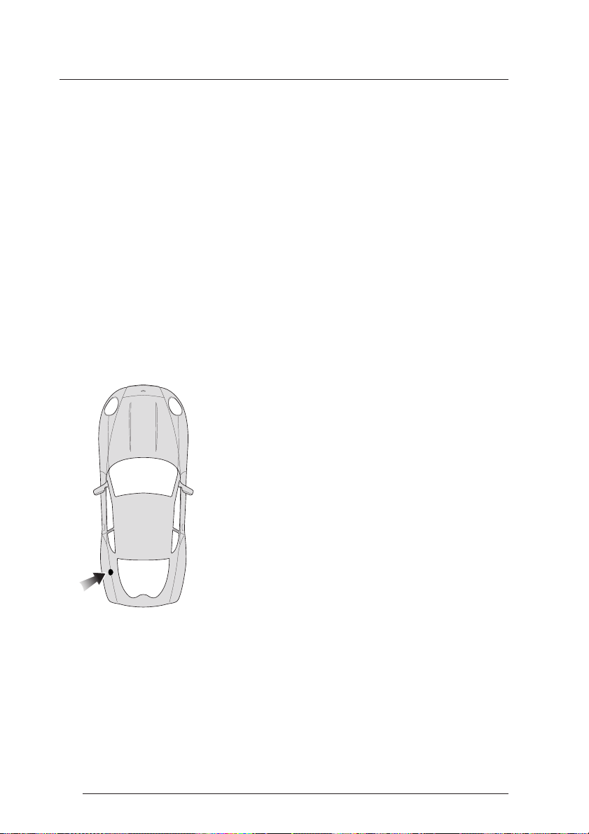
Location of Components
When reading component descriptions or when
following procedures in this Owner's Guide, the
following convention is adopted for locating items
within the vehicle.
viii
All directions are described as viewed from the
driver's seat. Thus the fuel filler cap indicated on this
diagram will be described as "located at the rear left
side of the vehicle".
Page 9
DB7 Zagato Owner's Guide
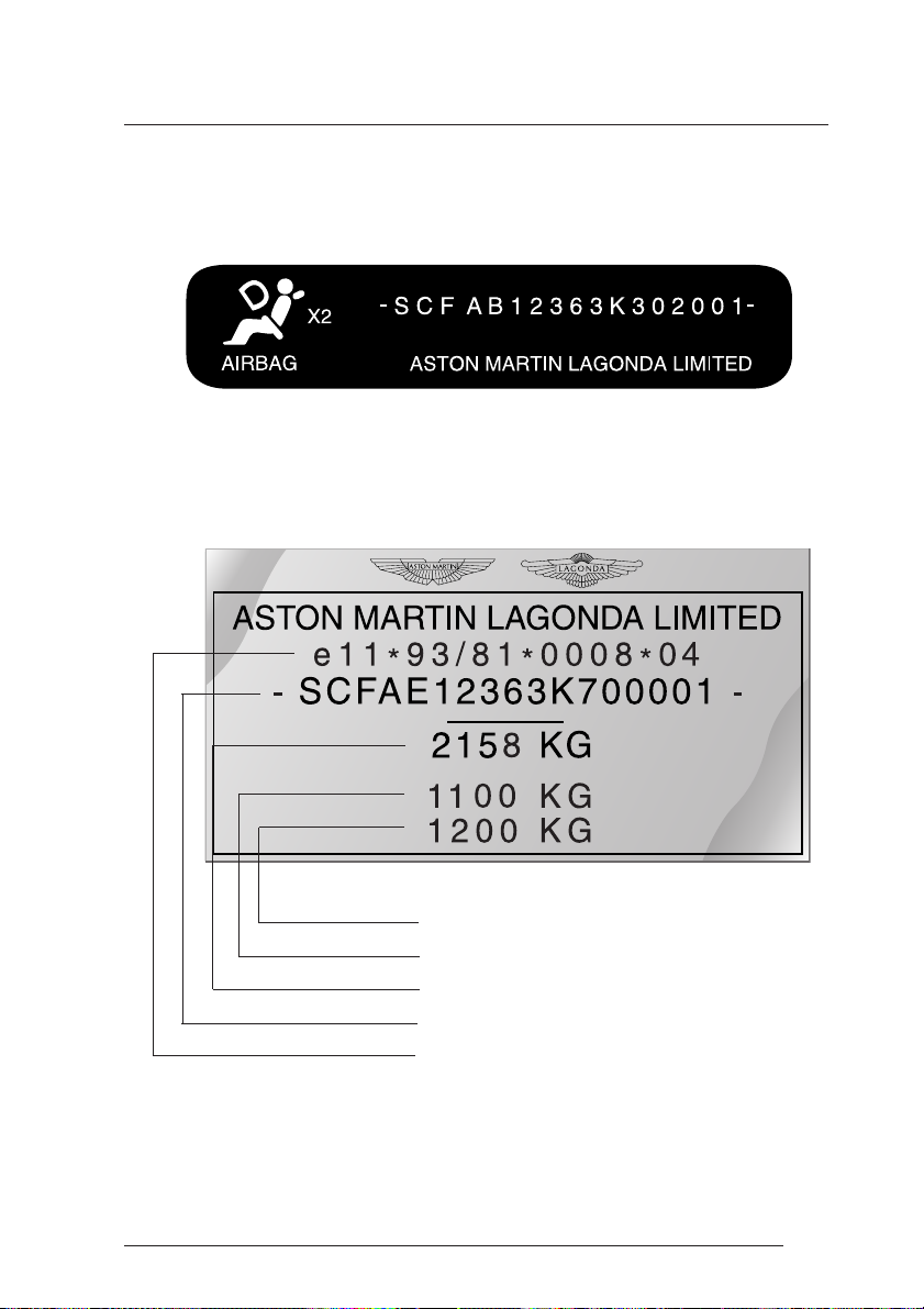
Vehicle Identification
The Vehicle Identification Number (VIN) is shown in the left hand lower
corner of the windscreen.
The Vehicle Identification Plate attached to the right front inner wing is
model and market dependant but typically contains the following types of
information:
Maximum Gross Rear Axle Weight
Maximum Gross Front Axle Weight
Maximum Permitted Laden Weight
Vehicle Identification Number
Model Type Approval Number
Note: Gross axle weight is the maximum permissible weight on a single axle. The
sum of the axle weights must never exceed the maximum permitted laden weight
of 2100kg.
ix
Page 10

DB7 Zagato Owner's Guide
Reporting Safety Defects
If you believe that your vehicle has a safety defect which could cause a crash
or could cause injury or death, you should immediately inform your Aston
Martin Dealer or the manufacturers service operations department at the
address below:
Aston Martin, Service Operations Department,
Banbury Road, Gaydon, WARWICK, CV35 0DB, England
Telephone (44) (0)1926 644700
Facsimile (44) (0)1926 644733
Regular Checks
In the interests of safety and reliability, it is advisable to carry out the
following checks at the intervals suggested (more frequently if the vehicle is
heavily used or operating in adverse conditions), and always before starting
on a long journey. Refer to the Owner Maintenance section of this guide.
Each Day
Check that there is sufficient fuel for the intended journey, particularly at
night and before entering highways.
x
Page 11

DB7 Zagato Owner's Guide
Weekly - (Daily if covering high mileage or touring)
Tyres - Check the tyres, for condition and pressure. See the 'Specifications'
section for the recommended tyre pressures.
Lights - Check that all exterior lights and direction indicators function
correctly and that the lenses are clean.
Engine Oil - With the vehicle standing on level ground, check the oil level
and top up if necessary with oil of the correct grade.
Engine Cooling System - With the engine cold, check the level of the engine
coolant. Top-up if necessary with coolant containing the required percentage
of anti-freeze. Any significant coolant loss should be investigated by your
Aston Martin Dealer.
Brake Fluid - Check the level of the fluid in the brake reservoir. Top-up if
necessary with the specified brake fluid from a new unopened container.
Power Steering Fluid - Check and top-up the level of fluid in the power
steering reservoir with fluid of the correct specification.
Monthly
Windscreen Washer - Top-up with the recommended windscreen wash
fluid. Check the operation of the windscreen washers. Use the recommended
concentration of additives to prevent freezing in winter conditions. Check
the windscreen wash fluid level more frequently if the wash system is being
heavily used.
xi
Page 12

DB7 Zagato Owner's Guide
xii
Page 13

A - Before Driving
Contents
Vehicle Keys ....................................................................................... 1-A-2
The Security System and Door Locks .................................................. 1-A-3
Adjustments Before Driving ................................................................ 1-A-7
Seat Belts ......................................................................................... 1-A-11
Airbags ............................................................................................. 1-A-17
Interior Storage ................................................................................. 1-A-19
1-A-1
Page 14
A - Before Driving
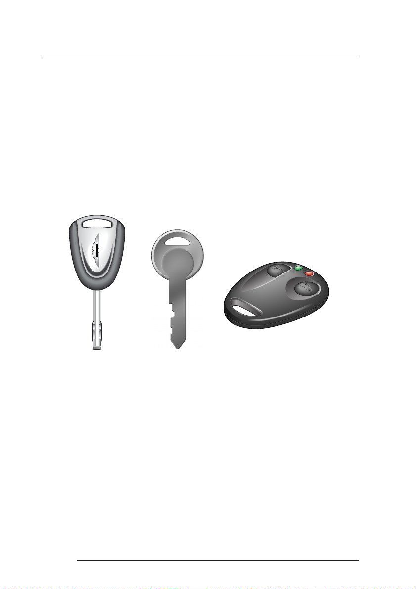
Vehicle Keys
Your DB7 Zagato is supplied with two sets of keys. Each set contains the
following:
One ignition/door key
One key number tag
One key for the centre armrest storage box
One alarm key fob
ASTON MARTIN
Security of Keys and Alarm Key Fobs
It is important to keep your keys and alarm key fobs in a safe place at all
times. Leaving them in a conspicuous place is an invitation for a thief to steal
them and consequently your car and belongings. Keep your key sets secure
at all times.
Remove the key number tags from each key set and keep them secure. They
will be required if you wish to obtain replacement keys.
1-A-2
Page 15
A - Before Driving
The Security System and Door Locks
Your DB7 Zagato is fitted with sophisticated security systems which protect
your car against theft. The alarm system is linked to the central locking
system. The following two pages describe the basic operations required to
turn on or off the alarm and at the same time to lock or unlock the car. The
systems are fully described in section 'E - Security Systems'.
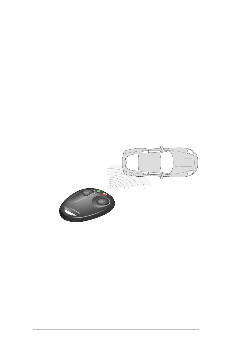
Alarm Key Fob
Basic alarm functions are controlled using the alarm key fob which sends
radio signals to the alarm unit aerial near the rear window when either the
left or right key fob button is pressed.
The left button is used for turning the alarm system on/off and locking/
unlocking the car. The right button is used for unlocking the boot.
The key fob has a range of about 10 metres (30 feet) when operating with
no intervening obstructions.
1-A-3
Page 16

A - Before Driving
Unlocking the Car / Turning off the Alarm
To unlock the car and turn the alarm system off, approach to within 10
metres (30 feet) of the car and point the key fob towards the rear window.
Press the left button on the alarm key fob.
The exterior direction indicators flash three times, indicating that the alarm
has been switched off. At the same time, the central locking system unlocks
the car doors and fuel filler flap. Alarm sensing on the boot lock is also
switched off so that the boot may be opened without triggering the alarm.
Locking the Car / Turning on the Alarm
To turn the alarm system on and lock the car, stand within 10 metres (30 feet)
of the car and point the key fob towards the rear window. Press the left
button on the alarm key fob.
The direction indicators flash once as the alarm is switched on. Alarm
sensing is then operative on the door locks, bonnet and boot. The glass
break sensor will also be activated. At the same time, the car doors, boot and
filler flap are locked by the central locking system.
Engine Immobiliser
The engine is immobilised by the Passive Anti-Theft System (PATS) and may
not be started until a correctly coded key is inserted and turned in the
ignition switch (See 'Security Systems' for a full description of PATS). The
PATS system is fully automatic and requires no intervention from the driver.
1-A-4
Page 17

A - Before Driving
Door Locks
The door locks and fuel filler flap are centrally controlled and are normally
unlocked when the left button is pressed on the alarm key fob. The boot lock
is also enabled at this time but does not release until opened using the boot
release switch or by pressing the right button on the key fob.
NOTE: If a door is unlocked and opened with the key whilst the alarm is switched
on, the alarm will sound.
If the alarm system is off, then locking or unlocking of either door with the
ignition key causes simultaneous locking or unlocking of the other door and
the fuel filler flap by means of the central locking system.
Door Sealing
Your DB7 Zagato is fitted with frameless door windows. A special door
sealing system is fitted to ensure a tight fit of the door glass to the seals around
the top of the door opening. This minimises wind noise and ensures a
watertight window seal.
When you open a door, the window glass is automatically lowered a few
millimetres to clear the door seal.
As you close a door, the window glass is automatically raised against the
body frame rubber seals.
WARNING: Ensure that all occupants are clear when the window mechanism is
operating.
Caution: Door Seal Damage - Reconnect the battery (see Battery Reconnect Switch
1-F-29) before opening the doors to avoid damage to the door seals.
1-A-5
Page 18
A - Before Driving
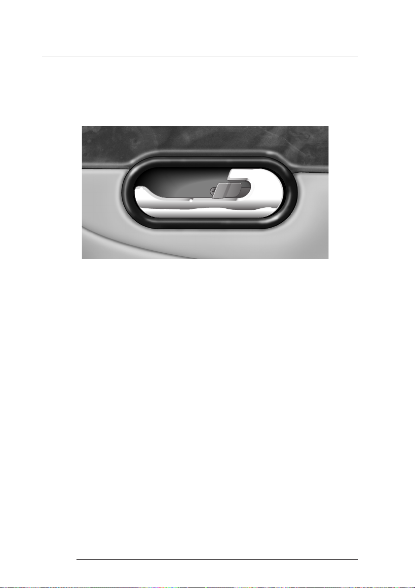
Interior Door Handles and Locks
To open either car door from inside, pull on the release lever and push
outwards on the door.
Locking the Doors when Inside the Car
If you wish to lock the car doors from inside the vehicle, push the lock tab
on the release lever towards the rear of the car. This will activate the central
locking system and lock both doors and the fuel filler flap.
WARNING: The interior door handle will also be disabled at this time.
Pushing the lock tab towards the front of the car will unlock the doors and
fuel filler flap.
1-A-6
Page 19
A - Before Driving
Adjustments Before Driving
When you get into the car you should check and, if necessary, adjust the
seat, steering wheel, interior and door mirrors, and secure your seat belt.
The controls for these functions are described on the following pages.
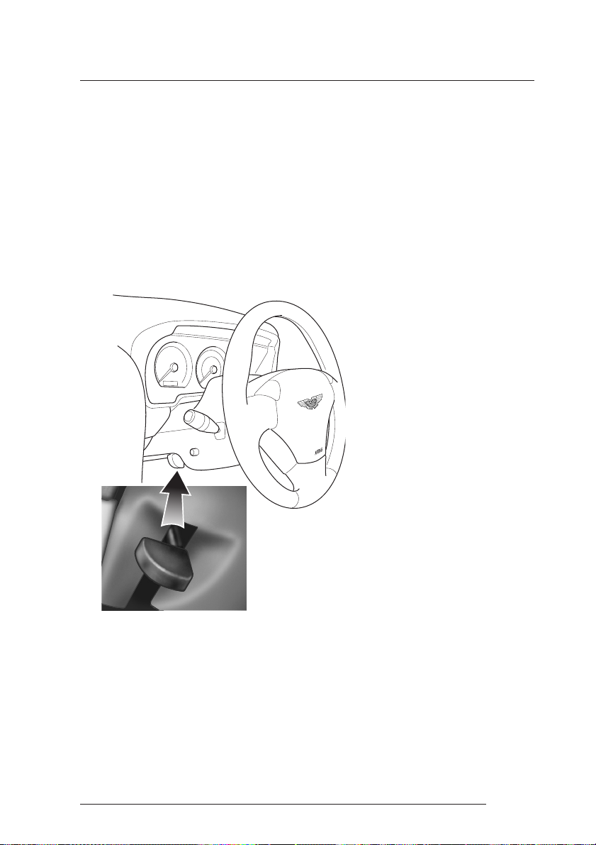
Steering Wheel
WARNING: Do not attempt to adjust the steering wheel whilst driving.
Rake
The rake of the steering wheel
is adjusted by using the release
lever to the left of the steering
column.
The steering wheel rake may
be locked in any one of four
positions.
Pull the release lever and apply
downwards pressure on the
steering wheel. Hold the wheel
in the desired rake position
and lock it by releasing the
lever.
After locking, attempt to move
the wheel up and down to
ensure that the lock is fully
engaged.
1-A-7
Page 20
A - Before Driving
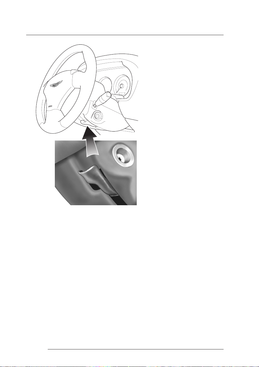
Reach
The reach to the steering wheel
may be adjusted by pushing
down the lever below the
steering column.
Adjust the reach position of
the wheel and then raise the
lever to lock the wheel
position.
After locking, attempt to move
the wheel in and out to ensure
that the lock is fully engaged.
1-A-8
Page 21
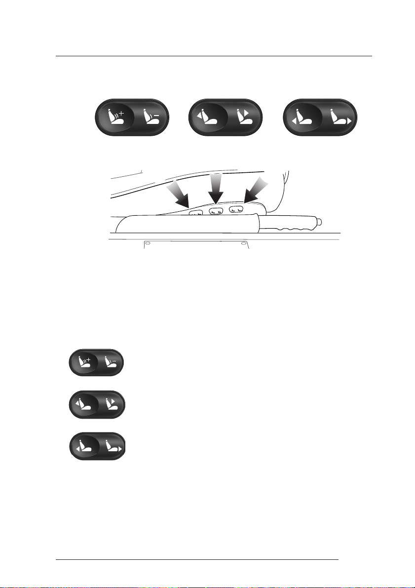
Seat Controls
A - Before Driving
B
A
WARNING: Do not attempt to adjust the seat whilst driving.
The Seat Control Panels
Three rocker switches are mounted on the outside of each front seat. The
switches may be operated with the ignition on or off.
Lumbar Support - Press either the + or - symbol on the
rear switch (A) to increase or reduce lumbar support.
Seat Back Angle - Use the centre switch (B) to increase or
decrease the angle of the seat back.
Front to Rear - Use the forward switch (C) to move the seat
in the front to rear direction.
C
1-A-9
Page 22
A - Before Driving
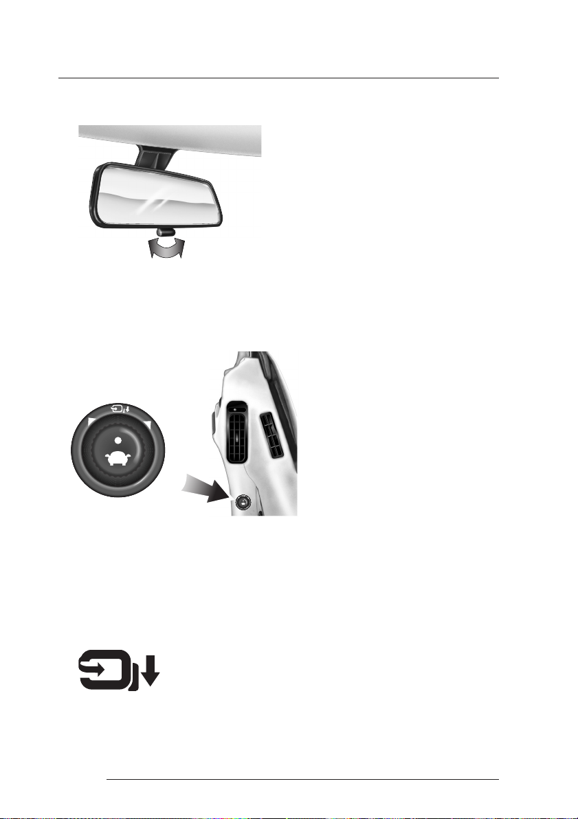
Interior Mirror
The interior rear view mirror can be
adjusted on it's ball mounting until a
satisfactory rear view is obtained when
sitting in the normal driving position.
The rear view mirror can be dipped to
reduce the glare from the headlights of
following vehicles.
Pull the tab towards the rear to dip the mirror. Push the tab forwards to reestablish the normal view.
Door Mirror Switch
The exterior door mounted
mirrors can be adjusted using a
single control knob mounted on
the driver's door.
Note: The ignition must be
switched on (position I or II)
before the door mirrors can be
adjusted
To select the mirror to be adjusted
rotate the knob left or right.
The joystick can then be moved forwards and backwards or to the left or
right to adjust the mirror up/down or left/right as required.
Powerfold Mirrors (Optional)
Push the control knob towards the mirror symbol and hold
to fold the door mirrors against the door when parked.
Repeat this procedure to unfold the mirrors before driving
the car.
1-A-10
Page 23
Seat Belts
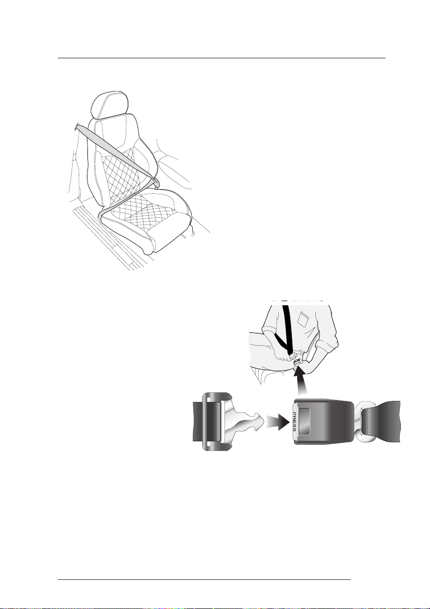
Seat Belt Fastening
Sit upright with your back
fully in contact with the seat
back. Pull out the seat belt,
drawing the tongue over
the shoulder and across the
chest.
A - Before Driving
The DB7 Zagato is fitted with two inertia
reel seat belts which automatically tension
to provide security with comfort. In the
event of a collision or during severe braking,
the belt reel will lock.
A light on the instrument panel is
illuminated when the car is started and the
driver's seat belt is not fastened. There is
also a brief reminder buzzer that sounds at
the same time.
Note: When parked on an
incline, the belt may lock as it
is withdrawn. This is not a fault.
If the mechanism locks, release
the belt tension and then pull
gently to avoid operation of
the inertia lock.
1-A-11
Page 24

A - Before Driving
Push the tongue into the belt buckle latch until a positive click is heard.
Pull upwards on the diagonal belt to ensure secure latching and to remove
all slack from the belt. Finally, double check that the lap belt is fitted snugly,
low down across the hips, and that there are no twists.
If it is necessary for an occupant to adjust their seat or seating position during
a journey, the belt tension might be disturbed. The occupant should
therefore (as soon as it is safe to do so) gently pull down the shoulder run
of the seat belt to create some slack and then immediately release it to retension the belt for the new seating position.
Seat Belt Pretensioner
The seat belt pretensioner system is designed to hold vehicle occupants
against the seat back when a frontal collision occurs.
The seat belt pretensioner system works in conjunction with the airbag
system. In a serious frontal impact, as the airbags are triggered, the
pretensioners will also be triggered. These apply additional tension to the
front seat belts to hold the front seat occupants back in their seats.
Automatic Locking Retractors (ALR)
All vehicles are fitted with an ALR seat belt in front passenger seat.
This system is designed to securely hold child seats. The ALR system
temporarily locks the belt securing the child seat.
1-A-12
Page 25

A - Before Driving
Securing a Child Seat (ALR System)
Fit the child seat following the manufacturers instructions. Gently pull out
the relevant inertia reel seat belt until fully extended. The ALR system will
only engage at the maximum extension point of the seat belt.
Thread the belt tongue through the child seat as instructed by the
manufacturer. Engage the tongue into the belt buckle. Adjust the tongue
position on the belt if necessary to ensure that the lower belt run is tight and
then allow the upper run of the seat belt to fully retract until the child seat
is securely held. The ALR system will be heard 'clicking' as the seat belt
retracts. When fully retracted, pull down on the upper run of the belt to
check that the ALR lock has engaged.
Child Seat Removal (ALR System)
To remove the child seat, release the belt as normal and allow it to retract
through the seat frame. The ALR system will disengage when the belt is fully
retracted. The belt may then be worn when required as a normal inertia reel
belt. Once the ALR is disengaged, the belt must be fully extended to reengage the system on the next occasion that a child seat is fitted.
WARNINGS - Seat Belts - General
Wearing your seat belt is crucial to your safety. Not wearing a seat belt increases
the chance of serious injury or death in the event of an accident. Be sure that you
and your passengers always fasten their seat belts and use them properly even
though airbags are provided. Seat belt usage is mandatory in most countries and
should be used in accordance with local laws.
By reclining the seat back, you decrease the protection you get from the seat belt
in the event of a crash. Adjust the seat back to an upright position (approximately
90° to the seat base.
1-A-13
Page 26

A - Before Driving
Seat Belts are designed to bear upon the bone structure of the body and should
be worn low across the front of the pelvis and across the chest and shoulders.
Wearing the lap portion of the belt across the abdominal area must be avoided.
Never place the shoulder portion of the belt under your arm or behind your back.
Always remove from your pockets rigid or breakable objects, such as spectacles,
which could be trapped under seat belts, possibly causing injury in the event of
an accident.
Expectant mothers should seek medical advice on the most appropriate way to
wear the seat belt.
In the interests of safety, seat belts must be kept clean so that the retractor works
correctly. Ensure that the belt webbing is not twisted, looped, frayed or
obstructed in any way. If in doubt about the condition or operation of the seat
belt installation, have it checked by your Aston Martin Dealer.
No modifications or additions should be made by the user which will either
prevent the seat belt adjusting devices from operating, or prevent the seat belt
assembly from being adjusted to remove slack.Never install accessories on your
seat belts.
USE OF CHILD SEATS IN THE EUROPEAN COMMUNITY
WARNING
Child Restraints
Aston Martin has not tested any child restraint systems for this vehicle, and does
not recommend any specific child restraint system.
The following table is supplied under EC Directive 77/541.
1-A-14
Page 27

A - Before Driving
Mass Group Seating Position
as indicated on the Front Passenger Second Row *
child safety seat packaging Outboard
0 = Up to 10kg (0-9 months) X X
0+ = Up to 13kg (0-18 months) X X
1 = 9 to 18kg (9 months to 4 years X X
11 & 111 = 15 to 36kg (4 to 12 years) X X
U = Suitable for "universal" category restraints approved for this mass group.
X = Seat position not suitable for children in the mass group.
* = Unsuitable for use with many child restraints due to limited space.
Please consult with local manufacturers of smaller forward facing restraint and
booster cushions. These manufacturers can supply you with advice on the safety
of their particular child restraints, the position that they recommend, and also
advice on fitting instructions.
Do not seat a child aged 12 or younger, or weighing 36 kg or less in the car without
an appropriate child seat or booster cushion. Please confirm that any child seat
or booster cushion you may fit in the vehicle has been designed for use in this
model, and that it conforms to local market requirements.
SPECIAL WARNINGS ON USE OF SAFETY RESTRAINTS FOR CHILDREN:
A child, regardless of age, should always be restrained when travelling in a
vehicle. The following precautions are strongly recommended.
Do not allow children to travel in the vehicle without restraint. Approved child
seats or harnesses should always be used.
1-A-15
Page 28

A - Before Driving
Each seat belt assembly must be used by only one occupant. It is dangerous to put
a seat belt around a child being carried on the occupants lap.
Child restraint anchorages are designed to withstand only those loads imposed
by correctly fitted child restraints. Under no circumstances are they to be used
for adult seat belts, harnesses or for attaching other items or equipment to the
vehicle
CHILDREN AND THE USE OF CHILD SAFETY SEATS
An infant or child that is not properly restrained can be seriously injured or killed
in a crash. Seat belts are designed for adults and larger children; infants and
smaller children must be restrained in an approved child safety seat.
All child restraint systems are designed to be secured by lap belts, or the lap belt
portion of a lap-shoulder belt. Children could be endangered in a crash if their
child restraints are not properly secured in the vehicle. If you choose to use a
child safety seat, follow the manufacturers instructions. Never hold a baby or
child on your lap while riding in the car.
Check the seat manufacturers instructions for proper use and installation - use
the correct size seat and properly secure the seat in the car in accordance with
the manufacturers instructions. Be sure to read and follow the 'Installation and
Use Instructions' provided with the child seat.
Remember that children who have outgrown child restraints should wear the
vehicle's seat belt.
CHILD SEATS AND PASSENGER AIRBAGS
DO NOT install a rearward facing child seat in the front passenger seat position.
If a front seat position must be employed, use only a forward facing child seat
with the passenger seat set as far rearwards as practical.
1-A-16
Page 29
A - Before Driving
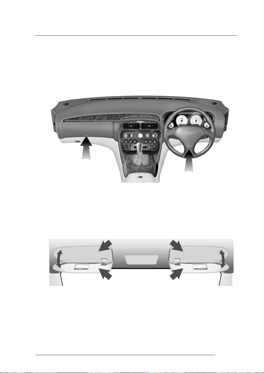
Airbags
In order to provide optimum occupant protection the DB7 Zagato is
equipped with a driver airbag mounted in the centre of the steering wheel
and front passenger airbag located in the fascia panel immediately in front
of the passenger seat. The airbags are supplementary to the seat belts.
Note: There are important airbag safety labels on the sun visors
(illustrated below).
Some models may have additional safety labels elsewhere, easily visible
to the vehicle occupants. Ensure that you have read and complied with
the instructions on these labels prior to driving the vehicle.
SECS
12
Do not change or modify or tamper with the steering wheel, passenger side
fascia or any other part of the airbag system. Such actions could disable the
system or cause inadvertent inflation.
1-A-17
Page 30

A - Before Driving
The airbags are designed to deploy only in a serious frontal collision. Their
purpose is to provide additional protection for the front seat occupants if
thrown forwards in an accident. The system is designed so that it will not
deploy in the event of trivial frontal impacts such as minor contacts when
parking. The airbag system is not designed to protect against side or rear
impacts.
WARNINGS:
No objects whatsoever should be attached to the centre cover of the steering
wheel or the passenger fascia panel. Such objects could cause harm if the vehicle
is in a crash severe enough to cause the airbags to deploy.
All occupants, including the driver, should always wear seat belts, whether or not
an airbag is provided , to decrease the risk of injury or death in the event of a crash
CHILD SEATS AND PASSENGER AIRBAGS
DO NOT install a rearward facing child seat in the front passenger seat position.
If a front seat position must be employed, use only a forward facing child seat
with the passenger seat set as far rearwards as practical.
Any work on the airbag system must only be done by an Aston Martin Dealer.
1-A-18
Page 31

A - Before Driving
Interior Storage
Door Storage
Open storage pockets are provided below the arm rests in both doors.
Front Armrest Storage
The front armrest lid is lockable.
The boot release switch and the
accessory socket are fitted in the
front armrest storage box.
Rear Storage
A rear storage area is provided
behind the driver and passenger
seats. Tie down straps enable
items to be secured.
1-A-19
Page 32

A - Before Driving
1-A-20
Page 33

B - Controls
Contents
Introduction ....................................................................................... 1-B-2
Information/Warning Lights ................................................................. 1-B-4
Instrument Panel Illumination ............................................................. 1-B-9
Instruments ...................................................................................... 1-B-10
Steering Column Controls - Left Hand Stalk ...................................... 1-B-12
Steering Column Controls - Right Hand Stalk .................................... 1-B-14
Steering Wheel ................................................................................. 1-B-15
Console Mounted Controls ............................................................... 1-B-16
Bonnet and Boot .............................................................................. 1-B-23
Accessory Socket .............................................................................. 1-B-26
Interior Lights ................................................................................... 1-B-27
1-B-1
Page 34

B - Controls
Introduction
Your DB7 Zagato has been designed to provide easy access to all primary
controls. The illustrations below show the main controls on the centre
console and instrument panel. The operation and function of each control
is described on the following pages.
1-B-2
Page 35

B - Controls
Take a moment to familiarise yourself with those controls which you will
require most frequently and with the additional functions which may be
required in an emergency.
1-B-3
Page 36

B - Controls
Information/Warning Lights
The Instrument Panel contains a number of information and warning lights
mounted above the instruments.
The information/warning light colours are significant and have the following
uses:
RED is used to warn drivers of concerns which may endanger them (e.g. Seat
Belt Warning, Brake System Warning, etc.) or to indicate potentially serious
problems with the car (e.g. Low Oil Pressure, Low Engine Coolant, etc.)
1-B-4
Page 37

B - Controls
AMBER is used for non-emergency indications such as Low Fuel, Low
Screen Wash Fluid.
GREEN signals the use of normal functions such as Direction Indicators.
BLUE is used to indicate that the Headlight Main Beams are on.
The following descriptions cover all instrument panel warning lights grouped
in the order, warnings (reds), cautions (ambers), and normal status lights
(greens and blue).
1-B-5
Page 38

B - Controls
Information/Warning Lights
Ignition Warning Light (Red)
Illuminates when the ignition is switched on. Extinguishes when
the engine is started and battery charging commences.
Brake Warning (Red)
Illuminates when the brake fluid level is low. May
illuminate with the ABS Warning Light.
Note: When the ignition is turned on, the Brake warning light will illuminate
briefly and extinguish if the brake fluid level is within specification.
Parking Brake Warning (Red)
Illuminates when the parking brake is applied
with the ignition On.
Low Coolant Level (Red)
Illuminates if the level of the engine coolant in the header is
tank is low.
1-B-6
Oil Pressure Warning Light (Red)
Illuminates when the engine oil pressure falls below minimum.
Do not continue driving if this light remains illuminated.
Consult your Dealer immediately.
Seat Belt Warning (Red)
This warning lamp will illuminate and a chime will sound if the
driver's seat belt is not fastened when the ignition is switched
on.
Hazard Warning (Red)
Flashes in time with the external indicator lamps when the
hazard warning lamps are switched on.
Page 39

B - Controls
Door or Boot Open (Red)
Indicates that any door and/or the boot is open.
ABS Warning Lamp (Amber)
Indicates a concern in the ABS control circuits. Consult your
Dealer immediately if this light remains illuminated.
Low Fuel Warning Lamp (Amber)
Illuminates when the fuel level drops to approximately 20 litres
(4.4 imp gallons).
Check Engine (Amber)
Indicates that an anomaly is detected in the engine management
system. The vehicle may go into 'Limp Home' mode with the
possibility of reduced engine performance.
If the lamp is on constantly, complete your journey and consult
your dealer at the earliest opportunity.
If the lamp flashes, a misfire is occurring which could damage
the catalytic convertor. Stop as soon as possible in a safe
location and have your car recovered to an Aston Martin
dealership.
Low Screen Wash (Amber)
Illuminates to warn you when the level of fluid in the screen
wash reservoir is low.
1-B-7
Page 40

B - Controls
SRS (Supplementary Restraint System) (Amber)
Flashes if a fault is detected in the airbag system.
When you start the car, this lamp comes on for a few seconds
as a readiness indicator. If it does not come on when you start
the car, or if it does not go off after a few seconds, or if it comes
on whilst driving, the airbag system has detected a fault. Consult
your Dealer immediately if this light illuminates.
Frost Warning Lamp (Amber)
This lamp will illuminate if the external temperature falls to
+4°C. At or below this temperature there is an increased risk
of frost on the road surface.
Traction Control Warning (Green)
Traction control is normally on. This lamp illuminates if the
system is switched off. The lamp flashes when traction control
is active. See the traction control description in this section.
Left Turn Direction Indicator (Green)
Flashes with the indicator lights during operation of the left turn
signal or hazard warning lights.
1-B-8
Right Turn Direction Indicator (Green)
Flashes with the indicator lights during operation of the right
turn signal or the hazard warning lights.
Headlights (Blue)
Shows when the main beam of the headlights are in use.
Page 41

B - Controls
Instrument Pack Chime
A warning chime will sound briefly to attract your attention if any of the
following warning lamps illuminate - ABS, Low brake fluid, Low coolant
level, Low fuel level, Low oil pressure, Boot open or a Frost warning.
The warning will be repeated each time the ignition is switched on until the
cause is cleared.
Instrument Panel Illumination
The level of instrument illumination can be adjusted using the rotary control
on the left hand side of the steering column.
1-B-9
Page 42

B - Controls
Instruments
Voltmeter (top left)
Shows the battery voltage when the ignition is turned on and shows the
voltage delivered from the alternator when the engine is running.
Fuel Gauge (bottom left)
The DB7 Zagato fuel capacity is 82 litres (18 Imp gallons). The low fuel
warning lamp will illuminate when approximately 20 litres (4.4 Imp gallons)
of fuel remain.
Note: Approximately 7 litres of the total fuel capacity specified above is required
to prime the fuel system and is therefore not usable.
Tachometer (centre left)
Indicates the engine speed in revolutions per minute x 1000.
Trip Meter/External Temperature Digital Display
The tachometer also contains the trip meter/external temperature display.
1-B-10
Page 43

B - Controls
Trip Meter - The trip meter may be used to record the distance travelled on
individual journeys. Whilst the trip reading is displayed, it may be set to zero
by holding the trip button pressed for more than two seconds.
External Temperature Display - Press the trip button briefly to display the
external temperature. Whilst the external temperature is displayed, press
and hold the button to change between °C and °F read-out. Briefly press the
button again to return to the trip display.
Speedometer (centre right)
Indicates the vehicle speed in miles per hour and/or kilometres per hour.
Also houses the odometer recording the total distance travelled by the
vehicle.
Oil Pressure Gauge (top right)
The oil pressure gauge is graduated in bar (1 bar 14.7 psi). Normal oil
pressure at medium engine revs should be in the range 3-6 bar.
Engine Coolant Temperature Gauge (bottom right)
In temperate climates, normal coolant temperature is indicated with the
needle to the left of the 'N' position, but coolant temperature will vary
(within the range 92 - 105°C) dependent on ambient temperature and
driving conditions.
1-B-11
Page 44

B - Controls
Steering Column Controls - Left Hand Stalk
The left column stalk controls the following functions:
Turn Signals
Move the stalk up to indicate a right turn, or down to indicate a left turn. The
stalk automatically returns to the centre position on completion of the
manoeuvre. The stalk may be moved partially up or down to bring on the
indicator lights to indicate a lane change. When released from the partially
up or down positions, the stalk is returned to the centre position by spring
pressure.
If an external indicator bulb fails, the remaining indicator lights on that side
of the car and the instrument panel warning light for that side will flash at
twice the normal rate when a turn to that side is indicated. If this situation
occurs, replace the defective bulb as soon as possible.
1-B-12
Page 45

B - Controls
Side and Headlight Switching
The left stalk collar has three positions that control the external running lights
of the vehicle: in the off position all external lights are off.
Rotating the collar to the first click (the side lamp symbol) switches on the
side lights, side marker lights, rear lights and registration plate lights (licence
plate lights).
Rotating to the second click position (the headlamp symbol) switches on the
headlight dipped beams in addition to the side, rear and registration plate
lights.
Main and Dipped Beam Switching
When the headlight dipped beams are switched on, they may be switched
to main beams by pushing the left stalk away from the steering wheel. Pulling
the left stalk back to its central position will switch the headlights back to
dipped beams.
Headlight Flashing
When all lights are off or when only the side lights are on, the headlight main
beams may be flashed by pulling the left stalk towards the steering wheel.
The headlights will go off when the stalk is released.
1-B-13
Page 46

B - Controls
Steering Column Controls - Right Hand Stalk
The right column stalk controls the following functions:
Windscreen Wiper Control
Upwards movement of the stalk from its lowest Off position switches the
wipers through the range Intermittent Wipe - Normal Speed Wipe - Fast
Wipe.
Windscreen Wiper Delay Control
When in the intermittent wipe position, the wiper delay interval may be
adjusted using the collar on the right stalk. The wiper delay increases by two
seconds for each of the five collar positions, Maximum rotation of the collar
away from the driver gives the shortest delay between wipes.
1-B-14
Page 47

B - Controls
Windscreen Washer Control
The windscreen washers are switched on by pressing the button on the end
of the right column stalk. The washers and wipers operate whilst the button
is pressed. On releasing the button, the washers stop immediately but the
wipers continue for a few strokes to clear any residual washer fluid from the
screen.
If the washer button is used during normal wiper operation, the washers
operate whilst the button is pressed and the wipers operate continually
irrespective of the washer operation.
Steering Wheel
Horn Push
The horn is sounded by pressing
either of the horn buttons above
the steering wheel pad.
1-B-15
Page 48

B - Controls
Console Mounted Controls
1-B-16
Page 49

B - Controls
The centre console contains the following controls:
Clock and PATS Status Light
Heating, Ventilation and Air-Conditioning Controls
Fog Lamp, Screen Heater (where fitted) and Seat Heater Switches
Radio Cassette Player (Control for the CD autochanger)
Hazard Light Switch
Starter Button
Traction Control Switch
Window Lift Switches
Cigar Lighter and Ashtray
The Heating, Ventilation and Air-Conditioning Systems are fully described
in the Air-Conditioning section of this Owner's Guide.
Clock
The clock in the centre of the air conditioning
control panel is set using the buttons on the clock
ASTON MARTIN
panel.
The left button is used to retard the time and the
right button to advance the time.
The small light between the time set buttons is the
PATS Status Light which is described in the Security
section of this Owner's Guide.
1-B-17
Page 50

B - Controls
Fog Lights, Screen Heater and Seat Heater Switches
The row of controls beneath the air-conditioning panel contains a variety of
switches. Your DB7 Zagato has an appropriate selection of switches as
detailed below.
Front and Rear Fog Lights
Front Fog Lights
The front fog lights can be switched on when the headlights or
sidelights are in use. They must be switched off when visibility
clears to reduce glare to the drivers of oncoming vehicles.
Rear Fog Lights
These lights may only be used in conjunction with the headlamps
or sidelamps. They should be switched on when fog is causing
restricted visibility. They must be switched off when visibility
clears to reduce glare to the drivers of following vehicles.
1-B-18
Heated Rear Screen
This switch controls the rear windscreen heater, which turns
off automatically after about 10 minutes if not turned off
manually.
Page 51

B - Controls
Heated Front Screen (Where fitted)
This switch, if fitted, controls the front windscreen heater
which turns off automatically after about 4 minutes if not
turned off manually.
Seat Heater Switches
Press to switch on the heater. Press the button a second time
to switch off the heater. The heater is thermostatically
controlled and maintains a constant seat temperature until
either the heater is switched off or the ignition is switched
off.
Radio/Cassette/CD Player
The radio/cassette player is located beneath the console switch panel. The
CD changer is fitted in the boot. Manufacturers operating instructions for the
in-car entertainment system are included with this Owner's Guide.
Hazard Warning Lights
The hazard warning light switch is located beside the
radio cassette player. When pressed, the external indicator
lights and side repeater lights will flash in unison.
Press the switch again to turn off the hazard lights.
Caution: Observe local laws on the use of hazard lights.
1-B-19
Page 52

B - Controls
Starter Button
This button is located on the drivers side of the radio
cassette player. It is used to start the engine after turning on
the ignition. See the detailed instructions in the 'Driving'
section.
The button will illuminate when the ignition is switched on.
The button lamp will extinguish when the engine starts.
Traction Control Switch
The traction control system is always switched on when the ignition is
switched on. The system may be switched off using this switch on the centre
console.
The traction control warning lamp in the instrument pack will illuminate to
warn you when the system is switched off.
1-B-20
Page 53

B - Controls
Electric Window Switches
On either side of the gear selector lever are two identical
rocker switches to control the movement of the electric
windows.
With the ignition on and the doors closed, press and hold
the down (hollow) arrow to lower the window.
Press and hold the up (solid) arrow to raise the window.
Note: The electric window will only operate if the door is
closed.
Electric Window 'One Touch Down' Feature
Briefly press and release the down (hollow) arrow to lower the window fully.
Pressing the button again will stop downward window movement.
WARNINGS: Clear all obstructions before raising the window. When leaving the
vehicle, remove the ignition keys. Misuse of window switches, especially by
children, can cause injury.
Note: If battery power to the electric windows has been interrupted for any
reason, they will fail to operate correctly until reset using the procedure described
in 'Owner Maintenance'.
1-B-21
Page 54

B - Controls
Cigar Lighter and Ashtray
The cigar lighter is located to the left of the ashtray and may be used when
the ignition switch is in positions I or II. It is heated by pushing down until
it clicks. The lighter will pop up when ready for use.
WARNING: The cigar lighter is heated to "Red Heat" when in use. Take care to
avoid burns and do not allow children to play with the lighter.
The ashtray may be removed for cleaning by sliding back the lid and pulling
the tray upwards. After cleaning it should be replaced and pushed down
until the locating springs click into position.
1-B-22
Page 55

Bonnet and Boot
Bonnet Release
The bonnet release
lever is situated on the
outside of the left
hand front footwell.
Pull the lever to
release the bonnet
latches. The bonnet
will be released and
will rise until captured
by the bonnet safety
catch.
Bonnet Safety Catch
B - Controls
The bonnet safety catch is located under
the bonnet rear edge on the drivers side
of the car (left side on left hand drive,
right side on right hand drive).
Push down slightly on the bonnet rear
edge whilst pushing forward on the
bonnet safety catch to release it. Lift the
bonnet until fully open. The bonnet is
held open by two gas struts.
1-B-23
Page 56

B - Controls
Closing the Bonnet
To close the bonnet, hold near the centre of the rear edge and lower until
approximately 450 mm (18 inches) from the latch mechanisms and then
release it. After closing the bonnet, ensure that both left and right hand
latches have fully engaged by pulling up at either side of the bonnet rear
edge.
WARNING: Before closing the bonnet, ensure that no one is obstructing
the closing area and that hands and clothing are clear. Remove tools,
cleaning cloths, etc. from the engine compartment.
Boot Release
WARNING: The open boot lid is not designed to take weight. Do not sit
or lean on the open boot lid. Do not place heavy objects on the boot lid.
There are three methods for opening the boot.
1. The boot lid may be released at any time using the right hand button on
the key fob.
1-B-24
Page 57

B - Controls
2. The boot may be opened by pressing
the boot release switch located in the
front cubby box at any time when the
alarm system is switched off and the
ignition is switched on.
3. In an emergency the boot can be
released from inside the cabin by pulling
down the emergency release handle.
Push the emergency release handle back
into position after releasing the boot.
Boot Closing
Close the boot lid gently and push forward until the lock engages. Slamming
of the boot lid may damage the lock mechanism or the boot seals.
1-B-25
Page 58

B - Controls
Accessory Socket
The accessory socket is mounted in the centre armrest beside the boot open
switch and may be used to power any 12 volt vehicle accessory requiring
a current of less than 15 amps.
The accessory socket is only live when the ignition key is inserted and the
switch is turned to position I or II.
WARNING: Damage to the electrical circuits will result if more than 15 amps is
drawn from the accessory socket.
Only connect accessories which are designed for use in a motor vehicle.
Read the manufacturer's instructions and ensure that you do not connect any
device which would exceed the current rating of the accessory socket.
1-B-26
Page 59

B - Controls
Interior Lights
The interior light assembly is mounted in the front windscreen header rail
and contains two 'eyeball' lamps and the front interior lamp. The 'eyeball'
lamps are controlled by the outer switches on the lamp assembly and may
be rotated to illuminate the driver or passenger seat areas.
The centre switch on the lamp assembly controls the operation of the front
and rear interior lights as follows:
12 sec
Front and rear interior lights on
Front and rear interior lights off
Front and rear interior lights come on when a door is opened and
remain on for approximately 12 seconds after a door is closed with
the ignition off.
1-B-27
Page 60

B - Controls
1-B-28
Page 61

C - Driving
Contents
Checks Before Driving ........................................................................ 1-C-2
The Ignition Lock ................................................................................ 1-C-5
The Block Heater (Optional) ...............................................................1-C-7
Starting the Engine - Hot or Cold ........................................................ 1-C-8
Stopping the Engine - Removing the Ignition Key ................................ 1-C-8
Fuel Cut-Off Switch ............................................................................1-C-9
Gear Changing ................................................................................. 1-C-11
Traction Control System .................................................................... 1-C-12
The Braking Systems .........................................................................1-C-14
1-C-1
Page 62

C - Driving
Checks Before Driving
Inspect the car to make sure that everything is according to the information
and specifications in this Owner's Guide.
Check the wheels, wheel nuts and tyres.
Check that all windows, mirrors and lights are clear and unobstructed.
Check that the boot and bonnet are closed.
Once you are in the car, check that the doors are closed.
Check that the seat, mirrors and steering wheel adjustments are correct.
Check that all gauges and indicators are reading correctly.
Check that the seat backs are in an upright position.
Check that all occupants have fastened their seat belts.
Fuel
DB7 Zagato uses 95/98 RON Unleaded fuel only. For optimum performance
and extended high speed driving, the use of 98 RON fuel is recommended.
Caution: Do not use unleaded petrol containing metal based additives, such as those
based on Manganese (often sold as MMT) and Iron (often sold as Ferrocene). The use
of fuel containing such additives could lead to catalyst failure which is not covered by
the vehicle warranties.
The DB7 Zagato total fuel capacity is 82 litres (18 Imp gallons).
Note: Approximately 7 litres of the total fuel capacity specified above is required
to prime the fuel system and is therefore not usable.
1-C-2
Page 63

C - Driving
Fuel Filler Cap
The fuel filler cap is located on the
left side of the car, to the left of the
boot lid. The filler flap is unlocked
automatically upon turning off the
alarm or upon operating the central
locking system by unlocking either
door lock with the ignition key.
Lift the filler flap. Release the filler
cap by rotating a quarter turn
anticlockwise, then lift off the cap.
WARNINGS: Fuel vapour is highly flammable, toxic and explosive. Always switch
off the ignition before refuelling. Do not overfill the fuel tank. Do not inhale fuel
fumes.
Never carry additional fuel in portable containers. They may leak, explode or
cause a fire, whether full or partially empty.
If you handle fuel improperly, it can ignite or explode and cause injury. Do not
smoke or light a flame while refuelling. Do not use mobile phones at filling
stations.
Do not use the car if there is fuel leakage or a persistent smell of fuel.
1-C-3
Page 64

C - Driving
Fuel Filling
The unleaded fuel tank filler neck has a restricted opening which will only
accommodate the fuel supply nozzle of unleaded fuel pumps.
To avoid fuel spillage, stop filling at the first automatic cutoff of the fuel
supply nozzle.
Catalytic Converters
The DB7 Zagato exhaust system contains 3-way catalytic convertors which
convert harmful exhaust gasses into less noxious substances and so reduce
environmental pollution. Catalytic converters operate at high temperatures
and continue to radiate a considerable amount of heat after turning off the
engine.
WARNINGS:
Leaded fuel will cause irreparable damage to the catalytic converters. If you do
inadvertently put leaded fuel into a DB7 Zagato, DO NOT START THE ENGINE.
DO NOT DRIVE THE CAR. Contact your Aston Martin Dealer immediately.
Do not park over dry grass, leaves or other combustible material. A significant
fire risk exists because of residual heat in the catalytic converters.
Do not drive through deep water. The rapid cooling of the catalyst may cause it
to break up. Replacement catalytic converters are expensive.
1-C-4
Page 65

C - Driving
The Ignition Lock
The Ignition Lock, located on the right side of the steering column, performs
the following functions:
Steering Lock
Ignition Switch
The switch has three positions:
Position O All systems off, steering lock engaged.
Position I Auxiliaries on (e.g. radio), steering lock released. Use this
position if the vehicle is being towed.
Position II Ignition and all other electrical systems on. This is the
normal running position.
1-C-5
Page 66

C - Driving
Warning Light Indications at Ignition On
As the ignition is switched on, the DB7 Zagato electronic control units each
complete a self check to ensure correct operation. During these checks, the
warning lights on the instrument panel will illuminate as follows:
Bulb Check - All warning lamps illuminate for about three seconds as a
bulb check.
The Ignition and Oil Pressure warning lights illuminate until the engine
starts.
The Check Engine light will illuminate during the engine management
self-check and will extinguish when the starter button is pressed.
The Seat Belt warning light illuminates and a gong sounds for six seconds
if the driver's seat belt is not fastened. On fastening the seat belt, the gong
immediately ceases. The warning lamp extinguishes at the end of the six
second warning period.
The ABS and Traction Control warning lights illuminate and extinguish
if the system self checks are satisfactory.
The Brake warning light will illuminate and extinguish if the brake fluid
level is within specification.
The SRS Airbag warning light will illuminate and extinguish if the SRS
Airbag control system check is satisfactory.
1-C-6
Page 67

C - Driving
Only the handbrake warning light should stay on after the engine has started
and is running correctly. The handbrake warning light will extinguish as the
handbrake is fully released.
Note: Other Information lights may remain on (e.g. Main Beam Warning or Low
Screen Wash) dependant on the vehicle state and switch settings at the time.
If either the ABS or Brake Fluid Warning lights remain illuminated, refer to
the description of Brake Warnings during 'Driving' later in this section.
The Block Heater (Optional)
In extremely low ambient temperatures, engine freezing may be prevented
by use of the optional engine 'Block Heater'. This electrical heating device
is fitted into the engine cooling system and has a supply connector located
in the engine bay.
The recommended engine coolant (50% water, 50% BASF D542) will
prevent freezing of the coolant down to about -40°C. Whenever there is the
possibility of such low temperatures, connect the heater supply lead to the
socket in the engine bay and then to an appropriate power outlet. Switch
on the electrical supply. Leave the heater on at all times when the
temperature is extremely low.
Switch off and then disconnect the heater before starting the engine and
driving off.
WARNING: Always switch off and disconnect the supply socket before connecting
or disconnecting the power supply cable from the heater connector.
1-C-7
Page 68

C - Driving
Starting the Engine - Hot or Cold
WARNING: Before driving the vehicle, ensure that you are wearing appropriate
footwear to efficiently operate the floor mounted pedals. Ensure that floor
mounted pedal movement is not restricted by floor mats or other objects trapped
beneath the pedals.
The engine can only be started with the clutch pedal fully depressed.
Insert the ignition key and rotate it to position II. Press the
starter button, wait until the engine fires, then release the
starter button.
Note: Do not press the accelerator during engine starting. The Electronic Engine
Management System automatically compensates for cold or hot start conditions
and makes appropriate adjustments to the fuel/air mixture and engine idle speed
without driver intervention.
Stopping the Engine - Removing the Ignition Key
To stop the engine, turn the ignition key anti-clockwise to position 0.
Note: If the Ignition Key is left in positions I or II and a door is opened, a warning
chime will sound to advise removal of the key.
1-C-8
Page 69

C - Driving
Fuel Cut-Off Switch
Your DB7 Zagato is fitted with an emergency
fuel cut-off inertia switch mounted on the
passenger side door pillar. This switch
operates to cut-off fuel supply to the engine
in the event of an accident, thereby reducing
fire risk.
If the engine cuts out and then does not
restart in such a situation, open the passenger
door and press the top of the cut-off switch
until it latches down. With the ignition on,
the fuel pumps will then run and fuel will
again be supplied to the engine. Restart the
engine as normal.
WARNING: To avoid the possibility of fire, do not reset the fuel cut-off switch if
you smell fuel.
Running-In
Your DB7 Zagato engine is fully hot tested during manufacture and no
special running-in procedures are necessary. Nevertheless it is prudent to
limit engine loads (e.g. by using lower gears on steep hills) during the first
4,000 km (2500 miles).
Maximum Engine Speed - Fuel Cut-Off
The maximum safe engine speed is 7,000 RPM. If this speed is exceeded,
fuel supply to the engine is gradually reduced. As the engine speed reduces
back to a safe level, fuel supply is progressively restored.
1-C-9
Page 70

C - Driving
Driving in Wet Conditions
When driving in wet conditions, water can build up under your tyres so that
they ride on a layer of water. This is called aquaplaning or hydroplaning.
When this happens, you have little or no control. Aquaplaning is more prone
to happening at higher road speeds if there is a lot of water on the road and
particularly if the tyres are also under inflated or approaching minimum
tread depth. Slow down when it is raining.
It is important to take bends or curves at a safe, reasonable speed,
particularly when driving on wet or slippery road surfaces.
Rapid acceleration or deceleration can cause loss of control, especially on
slippery surfaces. Use extra care when driving on such surfaces.
1-C-10
Page 71

C - Driving
Gear Changing
When operating the DB7 Zagato, the following warnings are of particular
importance:
WARNING: Do not skip one or more gears when downshifting, you could lose
control of the vehicle and injury could result.
WARNING: Shifting without correct operation of the clutch and throttle can
result in severe damage to the transmission and engine.
Gear Changing
The gear lever for the six speed manual transmission is spring biased to the
centre of the gate. Push to the left before selecting first or second gears and
to the right before selecting fifth or sixth gear.
Press fully to the right and forwards to overcome additional spring pressure
when selecting reverse gear. The reverse gear position has a solenoid lock
to prevent accidental engagement when driving forward.
1-C-11
Page 72

C - Driving
Traction Control System
On/Off Switch
The traction control system is always operational when the ignition is
switched on. The traction control system can be switched off at any time
using the switch in the centre console.
Traction Control Warning Lamp
To ensure that the system is working correctly, a warning
lamp is integrated into the instrument panel. When the
ignition is switched on, the lamp should illuminate for
approximately 2 seconds and will then extinguish if the
system is in working order.
If the lamp remains on after 2 seconds, a system fault is present and should
be investigated by your Aston Martin Dealer.
During normal operation, the light remains off until wheel slip is detected.
The warning lamp will then flash whilst the system controls the wheel slip.
The warning lamp remains illuminated if traction control is switched off.
1-C-12
Page 73

C - Driving
Traction Control Operation
WARNING: In all cases it remains the drivers responsibility to drive safely
according to the law and with due regard to prevailing conditions. The fact that
a vehicle is equipped with Traction Control must never allow the driver to be
tempted into taking risks which could affect his/her safety or that of other road
users. The addition of Traction Control cannot overcome the consequences of
applying too much engine power for the prevailing conditions.
The traction control system is designed to limit engine power when driven
wheel slip is detected. This most commonly happens when accelerating on
a slippery road or loose surface.
The system uses the vehicles ABS sensors to monitor the wheel speed of all
four road wheels. As soon as a driven rear wheel starts to spin due to the
application of too much power for the available grip, the system automatically
reduces engine power by temporarily adjusting the fuel supply. The brake
on the slipping wheel will also be applied as necessary until the wheel speed
matches that of the other wheels.
During activation, the system warning light will flash. The driver may
experience a loss in power or temporary 'misfire' as engine power is
reduced. These symptoms are normal and will clear as wheel spin is
eliminated and normal engine power is restored.
If traction control cuts in when driving on extended icy or slippery surfaces,
reduce engine power as necessary until the traction control warning light is
extinguished.
Caution: Do not maintain engine power at such a level that traction control is
activated for long periods (more than about one minute). The reduced fuelling levels
to the engine will cause the exhaust catalysts to overheat. Overheating of the exhaust
catalysts can destroy them.
1-C-13
Page 74

C - Driving
The Braking Systems
The Footbrake System
Your DB7 Zagato uses a vacuum boosted hydraulic braking system with antilock (ABS) function. This system ensures braking performance in keeping
with the vehicle performance.
The Anti-Lock Braking System (ABS) is continually monitored for correct
operation whilst the ignition is switched on. Should a fault occur, it will be
signalled by the Anti-Lock Warning Light.
Brake System Safety Features
The brake system tandem master cylinder is designed so that in the worst
case (barring major accident damage), only half the brake system could fail.
Even in the event of a major brake pipe fracture, at least two wheels will have
fully operative brakes.
1-C-14
Page 75

C - Driving
Bedding-In of New/Replacement Brake Pads
To ensure that brake pads and discs are correctly 'bedded-in' on new cars,
the factory road test the car and perform the following brake bedding-in
procedure:
1. Three light brake applications from 80-50 kph (50-30 mph) using normal
acceleration to 80 kph.
2. Three medium applications from 110-65 kph (70-40) mph using normal
acceleration up to 110 kph.
3. Two hard applications from high speed to 50 kph (30 mph), again using
normal acceleration.
4. Drive a further 8 km (5 miles) with minimal brake use.
5. Stop and allow the brakes to cool.
6. Drive a further 8 km (5 miles) back to the workshop with normal brake
use.
Aston Martin dealers are required to perform this routine each time brake
pads / discs are replaced.
Aston Martin require owner's to perform this routine if pads or discs are
replaced by a non-franchised workshop who will not know of the correct
bedding in procedure.
Failure to bed-in the brake pads / discs will result in reduced brake
performance and possible brake judder or squeal.
1-C-15
Page 76

C - Driving
Anti-Lock Braking System (ABS)
The anti-lock braking system (ABS) fitted to the DB7 Zagato helps prevent
the road wheels from locking and skidding during emergency braking,
helping steering and directional stability to be maintained.
If, in an emergency braking situation, the braking force applied begins to
exceed the tyre/road adhesion, the ABS system is activated to prevent the
road wheels locking. When this happens a pulsating effect is felt through the
brake pedal. This is a normal ABS effect.
WARNING: In all cases it remains the drivers responsibility to drive safely
according to the law and with due regard to prevailing conditions. The fact that
a vehicle is equipped with ABS must never allow the driver to be tempted into
taking risks which could affect his/her safety or that of other road users. The
addition of ABS cannot overcome the consequences of trying to stop in too short
a distance, cornering at too high a speed, or the risk of aquaplaning - where the
tyres are prevented from contacting the road surface by a layer of water.
The driver should always take road conditions into account. A slippery road
surface always requires more braking distance for a given speed, even with ABS.
Possible extensions of stopping distance compared to locked wheels may occur
during ABS operation on slushy snow, gravel, sand or certain heavily corrugated
or ridged warning sections of road surfaces.
1-C-16
Page 77

C - Driving
Brake Warning Indications During Driving
Your DB7 Zagato electronic control units continue to monitor correct
operation of the braking sub-systems while the vehicle is being driven. Two
brake warning lights are of particular importance.
The Anti Lock Braking (ABS) Warning Light
The ABS system is monitored for correct operation while the
ignition is switched on. If a fault is detected, the Anti-Lock
warning light will illuminate and the ABS system will be partly
or fully disabled.
The normal braking system will continue to function without anti-lock but
with full vacuum boosted braking to all road wheels being maintained. In
the event of an ABS fault, consult your Aston Martin Dealer immediately.
WARNING: If the ABS warning light illuminates, you should be aware that wheels
could lock during extreme braking or when braking on slippery surfaces. Take
additional care to avoid the danger of wheels locking.
The Brake System Warning Light
The braking system is continuously monitored for fluid level.
If only the brake warning light illuminates, it indicates that the
brake fluid has fallen below the acceptable level. It is essential
that the braking system is checked immediately, preferably by
an Aston Martin Dealer.
WARNING: If the brake warning light illuminates, you should immediately be
prepared for possible increased stopping distances and possible partial failure
of the braking system.
1-C-17
Page 78

C - Driving
The Handbrake
The handbrake lever is situated on the outside of the drivers seat. The
handbrake operates on brake drums within the rear wheel brake discs.
To engage the handbrake, pull up firmly on the lever without pressing the
release button. The handbrake ratchet will latch and the handbrake warning
light will illuminate. Note that this lamp is the only indication that the
handbrake is applied. The lever can then be lowered to its fully down
position.
To release the handbrake, pull up on the lever against spring pressure, press
and hold the lock release button whilst lowering the lever to its maximum
down position.
The handbrake warning light extinguishes when the handbrake is fully
released.
Caution: Always check that the warning lamp is correctly extinguished before moving
off. Do not attempt to drive the vehicle if the warning lamp remains on.
1-C-18
Page 79

D - Heating, Ventilation & Air Conditioning
Contents
The Air Conditioning System.............................................................. 1-D-2
Air Conditioning Controls .................................................................. 1-D-6
1-D-1
Page 80

D - Heating, Ventilation & Air Conditioning
The Air Conditioning System
The air conditioning system is used to maintain a selected temperature level
within the passenger compartment. The system has heating, ventilation and
air conditioning functions. The system offers other functions such as
humidity control, rapid demisting and defrosting of the windscreen and
recirculation of internal air to avoid drawing unpleasant fumes into the
vehicle.
Caution: If your DB7 Zagato has not been used for a period of two weeks or more,
ensure that the Air Conditioning system is started up with the vehicle engine
speed at idle, using a low temperature with a slow fan speed. Increase temperature
and fan speed, as required, as the Air Conditioning system warms up.
Heating/Cooling
Incoming air may be heated or cooled to a chosen temperature and then
distributed within the passenger compartment through a number of fixed
and adjustable vents. Once set, the chosen conditions will be maintained
by the computer controlled air-conditioning system.
1-D-2
Page 81

D - Heating, Ventilation & Air Conditioning
Internal Air Flow
Air flows into the car through the exterior intake grilles below the windscreen.
It then flows through the air-conditioning unit and into the passenger
compartment through a number of fixed and adjustable vents.
Air flows out from the passenger compartment through outlets in the rear
shelf. Ducts carry the air to ventilate the boot via openings in the top boot
liner. Finally, stale air is removed from the car through the boot side vents
connecting to outlets under both rear wheel arches.
1-D-3
Page 82

D - Heating, Ventilation & Air Conditioning
Ventilation
The air from the air-conditioning system is fed into the passenger compartment
through a distribution system with several outlets. The diagram below
illustrates the principal outlet positions.
Face Level Vents
The face level vents are controllable and can be adjusted, horizontally or
vertically. Air supply to these vents is closed off in heating and defrost modes.
To direct the air from any of the face
level vents, rotate the central thumb
wheel left/right or up/down.
1-D-4
Page 83

D - Heating, Ventilation & Air Conditioning
Door Mounted Vents
The door vents are also controllable and can be set to suit the occupants
requirements.
A lever at the top of each door vent controls the distribution and volume of
air.
In the mid position, unrestricted airflow is available from the door vent and
the side window vent.
Moving the lever towards the window symbol progressively closes off the
door vent and biases airflow to the side window vent.
Moving the lever towards the symbol progressively closes off the airflow
to both side window and door vents. This lever position may be used during
demist operations to ensure maximum airflow to the windscreen.
1-D-5
Page 84

D - Heating, Ventilation & Air Conditioning
Air Conditioning Controls
The air conditioning controls are located on two panels mounted either side
of the clock on the centre console.
Left Panel
The left panel contains the temperature and fan speed controls.
Temperature Control
This control sets the desired in-car temperature
for the system. Incoming air is cooled and then
heated or blended as required to maintain the
in-car temperature at the set level within the
operating range of the system.
Fan Speed Control
This five position switch is used to set the fan
speed: Off (Fan symbol), 1-Low, 2-Medium, 3High and Defrost. In Defrost mode the fans run
at high speed and supply air to the windscreen
and side screen vents only.
1-D-6
When the system is switched Off, (Fan symbol)
the complete system is OFF. The external air
inlets are closed, cutting off fresh air supply
from outside the car.
Page 85

D - Heating, Ventilation & Air Conditioning
Defrost (A/C Off)
In defrost mode, the system is
automatically switched to high fan speed
and maximum heat with no air
conditioning. The hot air is directed to the
screen and door vents only. The door
vents may be closed to direct maximum
air flow to the windscreen.
Right Panel (AC Mode Switch)
The right panel contains the mode switch and temperature differential
controls.
The mode switch settings are:
Economy (A/C off)
Manual Control
Auto Control
Demist
Recirculation
ECON (Economy)
In the ECON position, the air conditioning compressor is switched off.
Incoming air can be heated if required and the fan speed can be adjusted
to increase or decrease the airflow in the vehicle. This mode puts minimum
load on the engine and gives the best fuel economy with no air conditioning
(no cooling or dehumidifying of incoming air).
1-D-7
Page 86

D - Heating, Ventilation & Air Conditioning
MAN (Manual)
In Manual mode, the air delivered from the
vents remains at the temperature set on the
temperature control regardless of the
temperature inside the passenger
compartment. In this mode, incoming air is
also dehumidified and blended.
AUTO Control
This is the automatic mode of operation in
which the heating and cooling functions of
the system operate automatically, as
required, to maintain the selected in-car
temperature. In this mode, incoming air is
also dehumidified and blended.
Note: If the incoming air requires little heating or cooling when in AC mode, the
centre vent will close reducing the air flow in the upper part of the passenger
compartment. If more airflow is required, the Demist function can be used to
provide the same temperature level but with increased air flow to the windscreen
vents.
1-D-8
Page 87

D - Heating, Ventilation & Air Conditioning
DEM (Demist)
When this mode is selected heated air is directed
to the windscreen vents for demisting as well as
to the face level, footwell and door vents. Air
speed and temperature depend upon the fan
speed, in-car temperature selected and engine
temperature.
Recirculation
In Recirculation mode, all external air inlets are
closed and conditions within the vehicle are
maintained by drawing air from within the
cabin and heating or cooling it as required
before returning it to the passenger
compartment.
Recirculation mode avoids drawing noxious
fumes into the vehicle from outside. This mode
is not recommended for continuous use since
no fresh air is drawn into the vehicle and
drowsiness may occur.
The car interior may be rapidly cooled in
recirculation mode by selecting Recirculation,
Minimum Temperature and Fan Speed 3.
1-D-9
Page 88

D - Heating, Ventilation & Air Conditioning
Temperature Differential Control
This control sets the difference in temperature
between the air from the face vents and that
from the footwell vents.
To provide cooler air to the face, the differential
control should be set fully anticlockwise. If the
control is set fully clockwise, the air from the
face vents will be at the same temperature as
that from the footwell vents.
The differential control is only effective when
the temperature control is set to its mid position.
1-D-10
Page 89

E - Security Systems
Contents
Security Systems ................................................................................. 1-E-2
System Operation - Basic Controls ...................................................... 1-E-3
The Passive Anti-Theft System (PATs) ................................................... 1-E-7
Alarm System - Operating Summary ................................................... 1-E-9
Alarm Key Fob - Range and Battery Replacement.............................. 1-E-10
1-E-1
Page 90

E - Security Systems
Security Systems
The primary protection for your DB7 Zagato is provided by an electronic
security system. Protection is further enhanced by a passive anti-theft system
(PATS) which provides engine immobilisation measures if the wrong ignition
key is used. The total system has the following functions:
Remote Arming/Disarming via a Key Fob
Perimeter Sensing via switches on the doors, boot lid and bonnet
Glass Breakage Detection
Boot Release on the Key Fob
Panic Alarm triggered using the Alarm Key Fob
120dB Siren with battery back-up (in markets where audible sirens are
permitted)
Random Code Encryption to prevent electronic scanning or grabbing of
the key fob identity code
Passive Anti-Theft system
Tracker System (Optional - UK only excluding Channel Isles)
The Tracker hardware is fitted to UK cars only and may be activated for
any owner's who wish to subscribe to this additional vehicle security
system. Please consult your dealer for system details and subscription
rates
1-E-2
Page 91

E - Security Systems
System Operation - Basic Controls
The system is controlled using the two button key fob. The left (key symbol)
button controls the normal locking/unlocking of the car and arms/disarms
the alarm system. The right (boot open symbol) button controls the
unlocking of the boot. The Panic Alarm feature is operated using the left key
fob button.
The security system aerial is located below the rear window. The key fob
should be pointed towards this area of the vehicle to ensure a strong signal.
The normal operating range of the key fob is approximately 10 metres (30
feet).
The Passive Anti-Theft feature is fully automatic and is operated via a
transponder in the ignition key head which communicates with the engine
immobiliser circuits.
1-E-3
Page 92

E - Security Systems
Unlocking the Car, Disarming the Alarm
Point the key fob towards the rear window and press the left button once.
The following events will occur:
1. The green light on the key fob will light while the left button is pressed.
2. The car doors and fuel filler flap will unlock.
3. The direction indicators will flash (in markets where visible alarm signals
are permitted and programmed).
4. The alarm system will be switched off.
Locking the Car, Arming the Alarm
Point the key fob towards the rear window and press the left button. The
following events will occur:
1. The green light on the key fob will light while the left button is pressed.
2. The car doors and fuel filler flap will lock.
3. The direction indicators will flash once (in markets where visible alarm
signals are permitted).
4. The alarm system will be switched on.
1-E-4
Page 93

E - Security Systems
Alarm and Security System Protection
With the alarm system armed, any attempt to open a door, the boot or the
bonnet will result in full alarm activation.
The alarm will also be fully activated if the glass break sensor detects any
attempt to break a vehicle window.
(See also the engine immobilisation protection afforded by the PATs system)
Full Alarm Activation
When activated, the siren sounds for 30 seconds (in markets where audible
sirens are permitted) and the direction indicators flash (in markets where
visible alarm signals are permitted). After 5 minutes the alarm stops (i.e. the
direction indicators stop flashing) and returns to the armed state. The doors,
boot and filler flap remain locked throughout.
The alarm can be deactivated by pressing the left (Key) button on the key
fob. This will also disarm the alarm and unlock the doors and filler flap.
1-E-5
Page 94

E - Security Systems
Panic Alarm
The system has a panic alarm feature which can be activated whatever the
alarm state. This feature may be used to discourage offenders when you are
either inside the car or within the operating range of the alarm key fob
(approximately 10 metres / 30 feet).
To activate the panic alarm, press and hold the left key fob button for at least
three seconds. The system will enter the full alarm state.
Press the key fob left button again to stop the panic alarm and return to the
state prior to initial panic alarm activation.
If the panic alarm is not switched off using the left button, the siren will stop
after 30 seconds and the indicator flashing will deactivate after 5 minutes.
Boot Lock Control
To open the boot , press the right key fob
button. The key fob red lamp will stay on
so long as the right hand button is pressed.
The direction indicators will flash once
(in markets where visible alarm signals
are permitted), the siren will chirp once
(in markets where audible sirens are
permitted and programmed) and the
boot will unlock. It is not necessary to
disarm the alarm in order to use the boot
unlock feature.
Caution: Always ensure that the boot lid is securely closed after use. The boot interior
lights will be on when the lid is left partially open and will cause the vehicle battery
to discharge.
1-E-6
Page 95

E - Security Systems
The Passive Anti-Theft System (PATs)
The PATs system is a fully automatic engine immobiliser. The system consists
of a transponder inside the head of each ignition key and, around the
ignition lock, a transceiver aerial which communicates signals to the PATs
electronic control unit. The PATs control unit communicates with the
engine management controller to immobilise the engine until a valid code
signal is received from the ignition key.
Two coded keys are provided with the vehicle. These keys
ASTON MARTIN
Starting the Engine
fit the door locks and the ignition lock.
In the event of loss of one of the keys, duplicate keys can
be created and programmed from the other key by your
Aston Martin Dealer.
When the alarm system is disarmed and the vehicle key is turned in the
ignition lock, the PATs controller sends a signal to the ignition key. The
ignition key must respond with a valid code before engine start will be
enabled. If a valid code is received, the ignition system will operate
normally.
If the key code is not received, or is invalid, engine start remains disabled.
Caution: To ensure a trouble-free signal exchange between the key and the vehicle,
do not cover the key head with any metal object (e.g. another key).
1-E-7
Page 96

E - Security Systems
PATs Status
The PATs system state is shown by the red status
LED in the centre console.
The status LED will illuminate for three seconds
when the ignition is turned on and will extinguish
when a valid code is received from the ignition
key.
When the ignition is turned off, the status LED
will flash. This is the normal state when the
vehicle is parked with the ignition off and the
key removed.
If the status LED remains on when the ignition is switched on, the system is
in fail-safe mode. This means that the car will start, but PATs has a fault.
After one minute, the status LED will flash a fault code. Your Aston Martin
dealer can use this code to aid diagnosis of the PATs problem.
If the status LED continues flashing when the ignition is turned on, the
vehicle remains immobilised due to a fault in the system or an invalid key
code. Should this situation arise, try the spare key. If successful, source a
replacement for the faulty key. If problems persist with both keys, consult
your Aston Martin dealer.
During normal operation, the only indication that PATs is present is the PATS
status LED. The system is designed to be completely transparent to the
vehicle user.
1-E-8
Page 97

E - Security Systems
Alarm System - Operating Summary
Note: Siren and indicator lamp flashes are prohibited in some markets.
Panic Alarm
Siren On for 30 secs
Indicators Flash
5 minutes
Resets after
5 minutes
Alarm On
System Armed
Normal state - parked and locked
Press Left Button Once
Indicators flash
three times
(where permitted and
programmed).
Doors Unlock
Press Left Button Once
(where permitted and
Indicators flash
programmed).
Doors Lock
Press Left Button
for 3 seconds
once
Press Right Button
1indicator flash
1 siren chirp
(where permitted
and programmed).
Boot unlocks
Boot Open
Alarm Off
System Disarmed
Normal state when driving
Resets after
5 minutes
Panic Alarm
Siren On for 30 secs
Indicators Flash
5 minutes
Press Right Button
1 indicator flash
1 siren chirp
(where permitted
and programmed).
Boot unlocks
Press Left Button
for 3 seconds
1-E-9
Page 98

E - Security Systems
Alarm Key Fob - Range and Battery Replacement
The normal range of the alarm key fob is approximately 10 metres (30 feet).
If you need to come closer to the car before the key fob signal is effective,
the key fob battery probably needs replacing.
To replace the key fob battery, open the battery compartment using a small
flat bladed tool and remove the cover.
Lift out the two batteries noting the correct orientation (positive terminals
uppermost). Take care not to damage the upper electrical contact in the
battery compartment.
Fit replacement batteries (Two x Varta CR2016 3 volt batteries or similar),
observing the correct polarity. Refit the battery compartment cover and
press the outer end to engage the cover lock tab.
Test that the alarm system will arm/disarm when actuated using the key fob
from a range of approximately 10 metres (30 feet).
1-E-10
Page 99

F - Owner Maintenance
Contents
Introduction ........................................................................................ 1-F-2
Servicing Precautions ...........................................................................1-F-4
Fluid Level Checks ............................................................................... 1-F-6
Wheels and Tyres ..............................................................................1-F-13
The Vehicle Toolkit ............................................................................1-F-17
Vehicle Recovery ............................................................................... 1-F-20
Electrics .............................................................................................1-F-24
Fuse Boxes ........................................................................................1-F-32
Bulb and Fuse Replacement...............................................................1-F-36
Bodywork and Fittings .......................................................................1-F-49
Vehicle Cleaning ................................................................................1-F-49
Storing the Car - Recommendations ................................................... 1-F-53
1-F-1
Page 100

F - Owner Maintenance
Introduction
Owner Maintenance
Each item in the Service Schedules must be performed on time as failure to
do so may void the New Car Warranty or other warranties. It is the owner's
responsibility to see that the vehicle is maintained properly and in accordance
with the manufacturer's service schedules.
Due to the sophistication of the various systems and the specialised
equipment required to maintain the DB7 Zagato, owner maintenance
should be restricted to the routine procedures given in this Owner's Guide.
If you think that the car is not functioning properly, always return it to an
Aston Martin dealer to be checked professionally.
Electronic Fuel Injection
WARNING: Electronic Fuel Injection: If the fuel system is allowed to run dry
irreparable damage to the fuel pumps may occur.
The electronic fuel injection system requires special equipment and test
facilities to set up and maintain so that the car gives optimum performance
coupled with economy and reliability. You are, therefore, strongly advised
to entrust all service work to an Aston Martin Dealer.
WARNING: Any modifications/additions to the fuel system not specifically
designed by Aston Martin are prohibited. If done, they may cause damage to the
fuel system which in some circumstances could result in fire. It is recommended
that all Service Field Actions and Recalls are entrusted to an Aston Martin dealer.
1-F-2
 Loading...