

Page 1
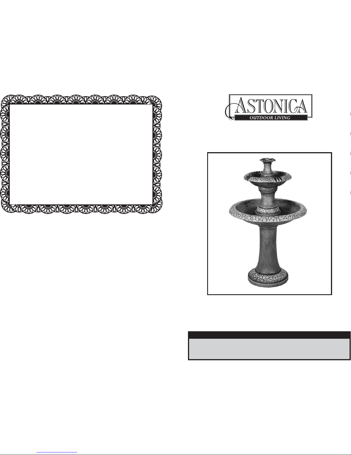
Model No. 40200091
Crackled Three Tier Fountain
Instruction Manual
Due to ongoing product development
the actual product or products may vary from
the illustrations or photos shown within this manual.
NOTE: This product is intended for residential, non-commercial use.
060911rev1
Read the instructions and precautions before use of this product
Please keep this instruction manual for future reference
®
For warranty information, please refer to the back page of
this instruction manual.
Made in China
©2011 World Factory, Inc.
Distributed by:
World Factory, Inc.
Westlake, TX 76262
Limited Warranty
World Factory, Inc. Products for Home Use
World Factory, Inc. (Seller) warrants to the original Buyer only, that each Astonica Product will be free
from defects in material and workmanship for a period of one (1) year from date of purchase.
SELLER’S SOLE OBLIGATION AND BUYER’S EXCLUSIVE REMEDY UNDER THIS LIMITED
WARRANTY SHALL BE THE REPAIR OR REPLACEMENT OF PARTS, WITHOUT CHARGE, WHICH
ARE DEFECTIVE IN MATERIAL OR WORKMANSHIP. ANY PARTS AS DETERMINED BY THE
SELLER WHICH HAVE BEEN MISUSED; ABUSED OR DAMAGED EITHER DIRECTLY OR INDIRECTLY
FROM REPAIRS OR ALTERATIONS ATTEMPTED BY UNAUTHORIZED PERSONS; IMPROPER
MAINTENANCE, NEGLECT OR ACCIDENT ARE NOT COVERED BY THIS LIMITED WARRANTY. This
warranty does not apply to damage, heat-induced coloration changes, scratching or alteration due to
normal use or weathering. To make a claim under this Limited Warranty, you must return the complete
product with proof of purchase, transportation prepaid, to any World Factory, Inc. authorized service
center. Call 1-888-422-7800 for the location of the nearest authorized service center.
Additional Limitations
THIS LIMITED WARRANTY DOES NOT APPLY TO ACCESSORY OR CONSUMABLE ITEMS RELATED
TO THIS PRODUCT. ALL IMPLIED WARRANTIES SHALL BE LIMITED IN DURATION TO ONE (1)
YEAR FROM DATE OF PURCHASE. IN NO EVENT SHALL SELLER BE LIABLE FOR ANY INCIDENTAL
OR CONSEQUENTIAL DAMAGES, INCLUDING BUT NOT LIMITED TO LIABILITY FOR LOSS OF
PROFITS, ARISING FROM THE SALE OR USE OF THIS PRODUCT.
If any provision of this Limited Warranty is for any reason held to be invalid or unenforceable, such
provision shall not affect any other provision herein, this Limited Warranty shall be construed as if
such invalid and/or unenforceable provision had never been contained herein.
This warranty gives you special legal rights, and you may also have other rights which vary from state
to state.
This Warranty contains the entire agreement between Seller and Buyer and supersedes any and all
prior agreements, arrangements, or understandings between the parties relating to product warranty.
Page 2
WARNING! ELECTRICAL SHOCK. Read and understand all instructions. Failure to follow all
instructions listed below, may result in electrical shock, fire and/or serious personal injury.
SAVE THESE INSTRUCTIONS.
Grounding Instructions
This fountain must be plugged into a 3-wire, 3-prong outlet that is properly working and has
been installed and grounded in accordance with all local, state or federal codes and ordinances.
DANGER: IMPROPER INSTALLATION OF THE GROUNDING PLUG CAN RESULT IN A RISK OF
ELECTRICAL SHOCK. Check with a qualified electrician or serviceman if the grounding instructions
are not completely understood, or if doubt as to weather the product is properly grounded. Do not
modify the plug provided; if it will not fit the outlet, have a proper outlet installed by a qualified
electrician. Do not use any type of adapter with this product.
Adjust Speed of Water Flow
1. Unplug pump (H) from AC power outlet.
2. Move adjustment switch on pump (F)
toward "+" positive to increase water
flow, or "-" to decrease water flow.
Maintenance
1. Check water level periodically, adding
water if necessary.
2. If water is not flowing, check electric pump (F),
and the clear tubing (G) for clogs.
NOTE: Pump may build up calcium after a
long period of time and stop running when
tap water is used. Any calcium remover can
be used to clean pump.
ELECTRICAL SAFETY INSTRUCTIONS
4
1
Grounded
Outlets
AMP Load Volts Extension Cord Length
120V 25' 50' 100' 150'
AWG
1-5 18 16 16 14
6-10 18 16 14 12
10-12 14 14 14 12
12-16 14 12
Not recommended
Table 1. Minimum Recommended Extension Cord Gauge (AWG) Chart
Outdoor Use Extension Cords.
1. When product is used outdoors, use only extension cords marked for outdoor use.
2. Use only UL listed extension cords. Never use damaged or altered extension cords.
3. Follow extension cord manufacturer safety instruction.
Extension Cords
1. Make sure your extension cord is in good condition.
2. When using extension cords, be sure to use one heavy enough to carry the current your product
requires. An undersized cord will cause a drop in line voltage resulting in power loss and
overheating. Reference Table 1 at the bottom of the page for the correct size to use depending
on cord length and nameplate Ampere rating. If in doubt, use the next heavier gage. The smaller
the gage number, the heavier the cord.
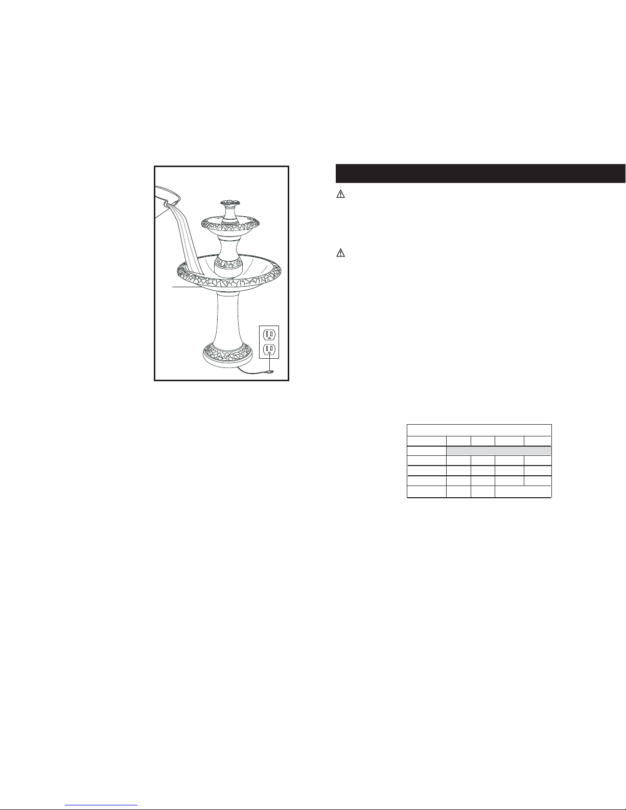
5. (SEE FIGURE 5) Fill the large basin (B) with
water. If possible use distilled water to
fill the basin.
6. Plug power adapter plug (F) into properly
grounded 120V AC outlet.
Figure 5
B
Page 3
ASSEMBLY INSTRUCTIONS
2
3
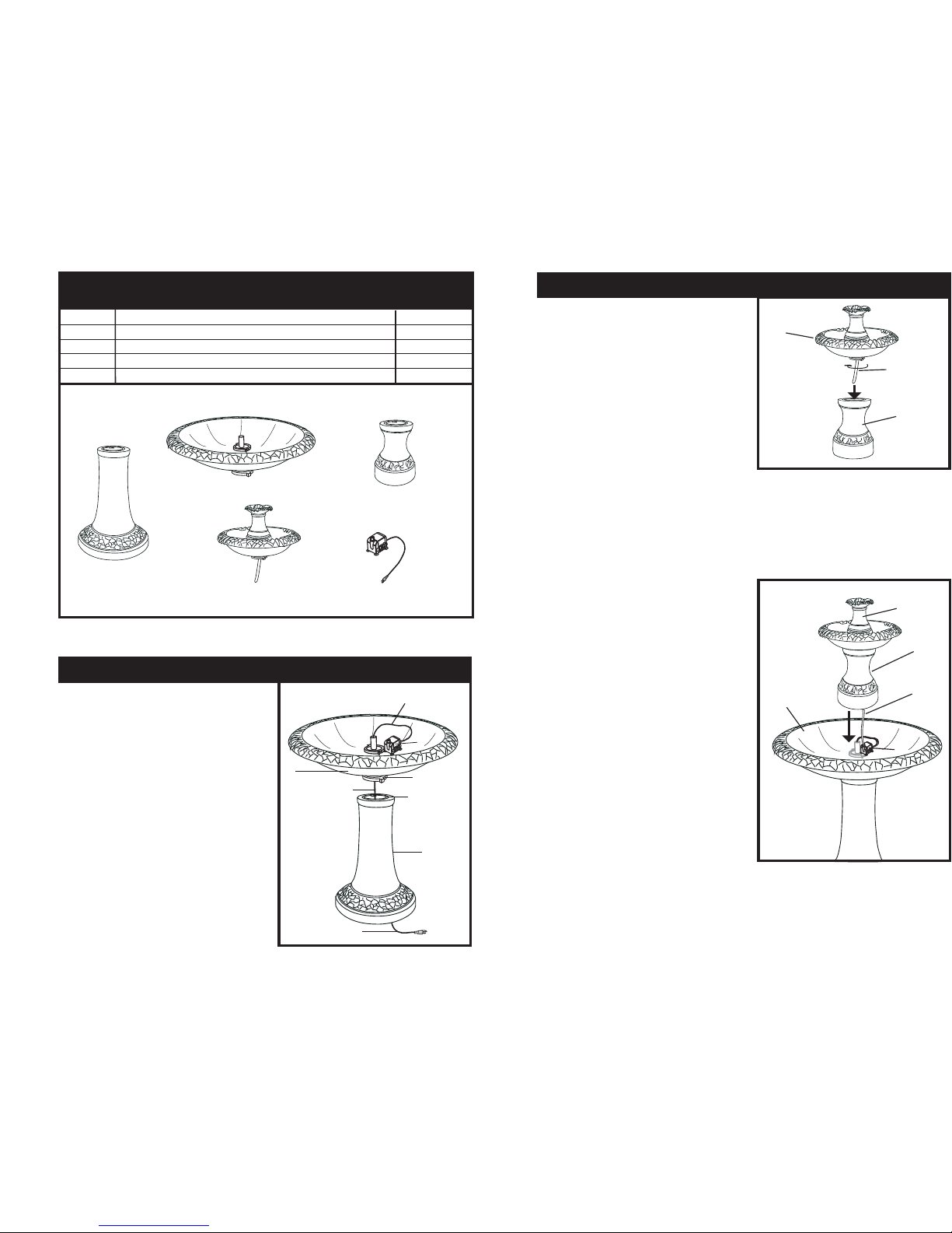
A Base Pedestal 1
B Large Basin 1
C Center Pedestal 1
D Small Basin 1
E Electric Pump 1
PARTS & HARDWARE LIST
PAR T #
DESCRIPTION QUANTITY
Carefully remove the contents from the package. If any parts are missing do not
attempt to use the product until they have been obtained and correctly installed.
D
C
Parts Detail
A
E
B
Figure 2
ASSEMBLY INSTRUCTIONS
1. (SEE FIGURE 1) Place the base pedestal (A) on
flat, level surface. Put the large basin (B) on the
base pedestal (A) aligning the tabs of the basin
with the notches in the top of the base pedestal
(A). Turn the large basin counter clockwise to
lock into place. Put the electric pump (E) into
the center ring in the bottom of large basin (B)
beside the PVC tube. Place the power cord of
the pump (E) through the PVC tube in the
pedestal base (A) and out the bottom of the base
as shown.
B
D
Figure 1
Power Cord
Power Cord
3. (SEE FIGURE 3) Connect the tube of the small
basin (D) to the spout on the electric pump (E).
4. Place the center pedestal and small basin
assembly (C,D) in the center of large basin (B)
making sure the electric pump (E) is inside the
center pedestal.
2. (SEE FIGURE 2) Feed the tube on the small
basin (D) through the center pedestal (C), then
connect the small basin (D) to the center
pedestal (C) by aligning the tabs of the small
basin with the notches in the top of the center
pedestal. Secure the small basin (D) by turning
counter clockwise onto the center pedestal (C).
3.
Basin Tab
Basin Notch
Power Cord
Figure 3
A
E
C
Tubing
C
D
Tubing
E
B
 Loading...