

Page 1

Installation, Operation and Maintenance User’s Manual
Aston Tire Changer Model# ATC-5800
ASTON TECHNOLOGIES, INC.
Page 2

Aston® Tire Changer ATC-5800 User’s Manual |
2
www.astontechusa.com
Semi-automatic swing arm tire changer
Parameters: rim: 10 "-28", Tire width:3"-16", tire diameter: 1160mm
Page 3

Aston® Tire Changer ATC-5800 User’s Manual |
3
www.astontechusa.com
Warning!
FAILURE TO OPERATE THIS EQUIPMENT AS DIRECTED MAY CAUSE INJURY OR DEATH. PLEASE READ
THIS ENTIRE MANUAL PRIOR TO INSTALLATION AND OPERATION. BY USING THIS PRODUCT, YOU
AGREE THAT YOU FULLY UNDERSTAND AND COMPREHEND THE FULL CONTENTS OF THIS MANUAL.
MAKE SURE ALL OPERATORS READ AND UNDERSTAND. KEEP YOUR INVOICE WITH THIS MANUAL FOR
FUTURE REFERENCE. MANUFACTURER SHALL NOT BE LIABLE FOR ANY INJURY TO PERSONS ON
DAMAGE TO THINGS CAUSED BY FAILURE TO COMPLY WITH THESE REGULATIONS AND CAN CANCEL
WARRANTY COVERAGE.
Failure to follow danger, warning, and caution instructions may lead to serious personal injury or death to operator or
bystander or damage to property. Do not operate this machine until you read and understand all the dangers, warnings and
cautions in this manual.
OWNER’S RESPONSIBILITY
To maintain machine and user safety, the responsibility of the owner is to read and follow these instructions:
• Follow all installation instructions.
• Make sure installation conforms to all applicable Local, State, and Federal Codes, Rules, and Regulations; such as State
and Federal OSHA Regulations and Electrical Codes.
• Carefully check the unit for correct initial function.
• Read and follow the safety instructions. Keep them readily available for machine operators.
• Make certain all operators are properly trained, know how to safely and correctly operate the unit, and are properly
supervised.
• Allow unit operation only with all parts in place and operating safely.
• Carefully inspect the unit on a regular basis and perform all maintenance as required.
• Service and maintain the unit only with authorized or approved replacement parts.
• Keep all instructions permanently with the unit and all decals on the unit clean and visible.
IMPORTANT SAFETY INSTRUCTIONS READ BEFORE OPERATING UNIT
• Read and understand all safety warning procedures before operating the machine.
• Before performing any services or maintenance, always disconnect the machine from its air supply source. Pump the
bead breaker pedal several times to evacuate all compressed air from the machine and disconnect the unit from its
electrical supply source.
• Keep hands and feet clear. Remove hands and feet from any moving parts.
• Keep work area clean and dry. Cluttered, damp or wet work areas invite injuries.
• Keep children away from work area. Do not allow children to handle this machine.
• Consider work area environment. Do not expose equipment to rain. DO NOT use in damp or wet locations. Keep
area well lighted.
Page 4

Aston® Tire Changer ATC-5800 User’s Manual |
4
www.astontechusa.com
• Only trained operators should operate this equipment. All non-trained personnel should be kept away from work
area. Never let non-trained personnel come in contact with or operate machine.
• Use machine correctly. Use machine in the proper manner. Never use adapters other than what is approved by the
manufacturer.
• Do not override or disable safety valves and/or devices.
• Always insure that all safety procedures are followed before any attempt is made to work on or near the equipment.
• Dress properly. Non-skid steel-toe footwear is recommended when operating machine.
• Guard against electric shock. This equipment must be grounded while in use to protect the operator from electric
shock. Never connect the green power cord wire to a live terminal. This is for ground only.
• DANGER! The motor on this machine contains high voltage. Disconnect power at the receptacle before
performing any electrical repairs. Secure plug so that it cannot be accidentally plugged in during service.
• WARNING! RISK OF EXPLOSION. This equipment has internal arcing or sparking parts which should not be
exposed to flammable vapors. This machine should not be located in a recessed area or below floor level.
• Maintain with care. Keep unit clean for better and safe performance. Follow manual for proper lubrication and
maintenance instructions. Keep control pedals and/or buttons dry, clean and free from grease and oil.
• STAY ALERT. Watch what you are doing. Use common sense. Do not use tools when you are tired or distracted
from the job at hand.
• Check for damaged parts. Check for condition of all moving parts, breakage of parts or any condition that may
affect the machines operation. Do not use if any component is broken or damaged. Replace or repair damaged or
worn parts immediately.
• Never remove safety related components or device from the machine. Do not use if safety related components are
damaged or missing.
• To reduce fire hazard, keep engine/motor exterior free of oil, solvent, or excessive grease.
• Illegible and missing warning labels must be replaced immediately. Do not use the tire changer if one or more
labels are missing. Do not add any object that could prevent the operator from seeing the labels.
TIRE AND WHEEL SERVICE SAFETY INSTRUCTIONS
Only properly trained personnel should service tires and wheels. Read all safety and operating instructions thoroughly
before use. The following safety instructions are for one-piece wheels only.
• Always refer to the manufacturer’s procedures for multi-piece wheels.
• The machine must be connected to a power supply line circuit bracket set for 30mA.
• Always keep all working surfaces clean and free of debris.
• Always wear durable personal protective work clothing and safety gear during tire service activity.
• To avoid personal injury and/or machine damage, always make sure the tire rim is firmly secured on the tire changer
with the jaws.
• Always remove all wheel weights and the valve core to deflate the tire before servicing.
• Never place your hands between the vehicle wheel rim and the jaws during the locking/clamping stage.
• Always be aware of what each person is doing and what they will do before attempting any two-person operation.
• Always cover the electric motor and switch box before cleaning the tire changer. Be sure water or cleaner does
not enter the motor or switch box.
Page 5

Aston® Tire Changer ATC-5800 User’s Manual |
5
www.astontechusa.com
• Always disconnect the electric power and air supply before attempting any maintenance.
Demounting & Mounting
• Always clean and inspect the wheel prior to any service.
• Never stand on the frame or work table while demounting or mounting a tire.
• Always keep hands, feet, and other objects away from moving parts while the machine is turned on.
• Always place the narrow bead seat to the outside when clamping. Failure to demount the tire from the narrow bead seat
side may cause damage to the tire beads.
• Always apply an approved rubber lubricant to rim flanges and both tire beads before demounting or mounting and
seating the beads.
• Never mount a tire on a damaged or rusty wheel as tire or wheel failure may result during inflation. Explosion from
failure may result in severe injury or death of the operator and bystanders.
Inflation
• Always be sure the bead opposite the tool is in the drop center before rotating the tire when demounting or mounting to
avoid damage to the tire beads.
• Always follow all applicable Local, State, and Federal Codes, Rules, and Regulations; such as the Federal OSHA
Standard Number 1910.177.
• Always use an approved inflation chamber or inflation cage equipped with a self-gripping chuck and remote inflation
gauge and valve.
• Always inflate the tire to manufacturer’s recommended cold operating pressure.
• DO NOT OVER INFLATE! Tire or wheel failure during and after inflation may result in an explosion capable of causing
severe injury or death.
• Never reinflate a tire that has been run under inflated or flat without first demounting the tire and checking for wheel
and tire damage.
• Always inspect the tire interior for loose or broken cords, cuts, penetrating objects, and other damage. Discard tires that
cannot be properly repaired.
• Never rework, weld, heat or braze wheels.
• Never strike the tire or wheel with a hammer.
• Always be sure the tire diameter exactly matches the wheel diameter.
Danger!
Tire failure under pressure can be hazardous. When possible, always place wheels inside an approved inflation chamber or cage
before inflating. Use an approved remote inflation valve, hose, and gauge. Always wear safety goggles for eye protection. Do
not stand beside the wheel or cage during inflation. Keep hands and other parts of the body out of the cage during inflation.
Observe the tire pressure frequently. Do not exceed the manufacturer’s recommended maximum inflation pressure. Failure to
follow these instructions may cause the tire and rim to separate with tremendous force, resulting in serious personal injury or
death.
Page 6

Aston® Tire Changer ATC-5800 User’s Manual |
6
www.astontechusa.com
TABLE OF CONTENTS
Overview ............................................................................................................................................................................... 8
1.1 Important note ......................................................................................................................................................... 8
1.2 Qualified users ........................................................................................................................................................ 8
1.3 Notes ....................................................................................................................................................................... 8
1.4 Danger warning signs ............................................................................................................................................ 10
1.5 Noise standard ....................................................................................................................................................... 10
Equipment description ........................................................................................................................................................ 11
2.1 Product introduction .............................................................................................................................................. 11
2.2 Specifications ........................................................................................................................................................ 11
2.3 Transportation ....................................................................................................................................................... 11
2.4 Figure and part name .......................................................................................................................................... 12
Installation and commissioning instructions ....................................................................................................................... 14
3.1 Installation Preparation ......................................................................................................................................... 14
3.2 Precautions during installation .............................................................................................................................. 15
3.3 Main installation procedure................................................................................................................................... 16
3.4 Check the project table after installation ............................................................................................................... 17
3.5 Commissioning and debugging ............................................................................................................................. 17
Operation............................................................................................................................................................................. 18
4.1 Operating notes ..................................................................................................................................................... 18
4.2 Disassembly operation process ............................................................................................................................. 18
Page 7

Aston® Tire Changer ATC-5800 User’s Manual |
7
www.astontechusa.com
4.3 Mounting……………………………………………………………………………………………………………………………………………………… 24
Maintenance ........................................................................................................................................................................ 35
5.1 Maintenance .......................................................................................................................................................... 35
5.2 Storage and scrap .................................................................................................................................................. 38
Fault causes and Solutions .................................................................................................................................................. 38
Parts List & Exploded Drawings ........................................................................................................................................ 40
Warranty……………………………………………………………………………………………………………………………………………………………………….41
Page 8

Aston® Tire Changer ATC-5800 User’s Manual |
8
www.astontechusa.com
Overview
1.1 Important note
1.1.1 Thank you for your purchase and use of this product. Please read and follow the safety
instructions. Keep them readily available for machine operators.
1.1.2 Service and maintain the unit only with authorized or approved replacement parts.
1.2 Qualified users
1.2.1 Make certain all operators are properly trained, know how to safely and correctly
operate the unit, and are properly supervised.
1.2.2 Electrical appliances must be operated by the normal electrician.
1.2.3 Do not attempt to operate this equipment if you have never been trained on basic tire
service and mounting / dismounting procedures.
1.3 Notes
1.3.1 Before using the product, please carefully read every part of the manual, especially the
operation of the safety and mechanical maintenance of the part.
1.3.2 Use the tire assembly machine must be operated by professional training personnel.
1.3.3 Tire disassemble is forbidden to use in explosive gas.
1.3.4 Before the machine is connected, the user must ensure that the use of power and gas
supply and mechanical requirements, the circuit system must be operated by professional
staff.
1.3.5 In the operation process, do not face close to the turntable, so as to avoid dust and
other debris hit the operator's eyes. In order to ensure safety, mechanical operation, to be
careful, do not touch the inflatable pedal, so as to avoid accidents.
1.3.6 To operate tire inflation must be very careful, strictly according to the instructions for
operation, if the tire suddenly burst, tire assembly machine design and structure is not to
protect the operator's personal safety (or any mechanical in the vicinity of the kind).
1.3.7 Operation of the tire changer, necklace, loose clothing, etc., may give the operator to
bring personal injury.
1.3.8 In the process of removing or installing the operation of the tire, the turntable has
always been to ensure that the clockwise rotation; if there is a counter clockwise rotation
Page 9

Aston® Tire Changer ATC-5800 User’s Manual |
9
www.astontechusa.com
indicates that the turntable is a failure or operator error.
1.3.9 Manufacturers are responsible for the damage caused by the use of other parts of the
manufacturer or the damage of the safety device.
1.3.10 periodically check the oil mist, oil, if the oil level is low and need to unscrew the oil
cup and then add. Oil mist using models for ISO Hg and viscosity for ISO vg32 oil mist
special oil (such as: Esso Fedis k32, 1405, Mobil Acauline, KLUBER32)
1.3.12 if the product is not used for a long time, please user A. disconnect all power supply,
B. and lubricate the turntable fixture slide to prevent oxidation.
1.3.13 when deciding to scrap equipment, to determine the total energy of all the energy to
be cut off, according to the relevant laws and regulations for all non-ferrous metals and non-
ferrous metal scrap processing.
Page 10
Aston® Tire Changer ATC-5800 User’s Manual |
10
www.astontechusa.com
1.4 Danger warning signs
1.5 Noise standard
The noise of the tire changer shall be less than 70dB. for your health, and it is recommended
that you place a noise meter in your operating area.
Page 11

Aston® Tire Changer ATC-5800 User’s Manual |
11
www.astontechusa.com
Equipment description
2.1 Product introduction
This model of semi-automatic tire changer is a half - automatic, convenient and quick
disassemble and installation of wheel size of 10” to 28”, the tire width of 110-380mm and
the diameter of the tire is 1040mm.
2.2 Specifications
Special points
Specifications
Outer rim
12"-26"
Inner rim
14"-28"
Maximum tire diameter
46"/1160mm
Maximum tire width
17"/425mm
Pressing force (10bar)
5731 lbs. (2600kg)
Operating air pressure
8bar-10bar(116-145psi)
Maximum charge pressure
3.5bar(50psi)
Power supply voltage
120V1ph/220V 1ph/380V 3ph
Motor power
1.1kw/0.75kw/1.5kw
Outline dimension
968×992×1800
Net weight
595 lbs. (270kg)
Working state noise
<70dB(A)
2.3 Transportation
Handling of the machine must be performed only with an appropriate lifting device such as a forklift
or pallet jack. Only personnel who are experienced and qualified on material handling procedures
should handle any transportation or moving of machine..
Page 12

Aston® Tire Changer ATC-5800 User’s Manual |
12
www.astontechusa.com
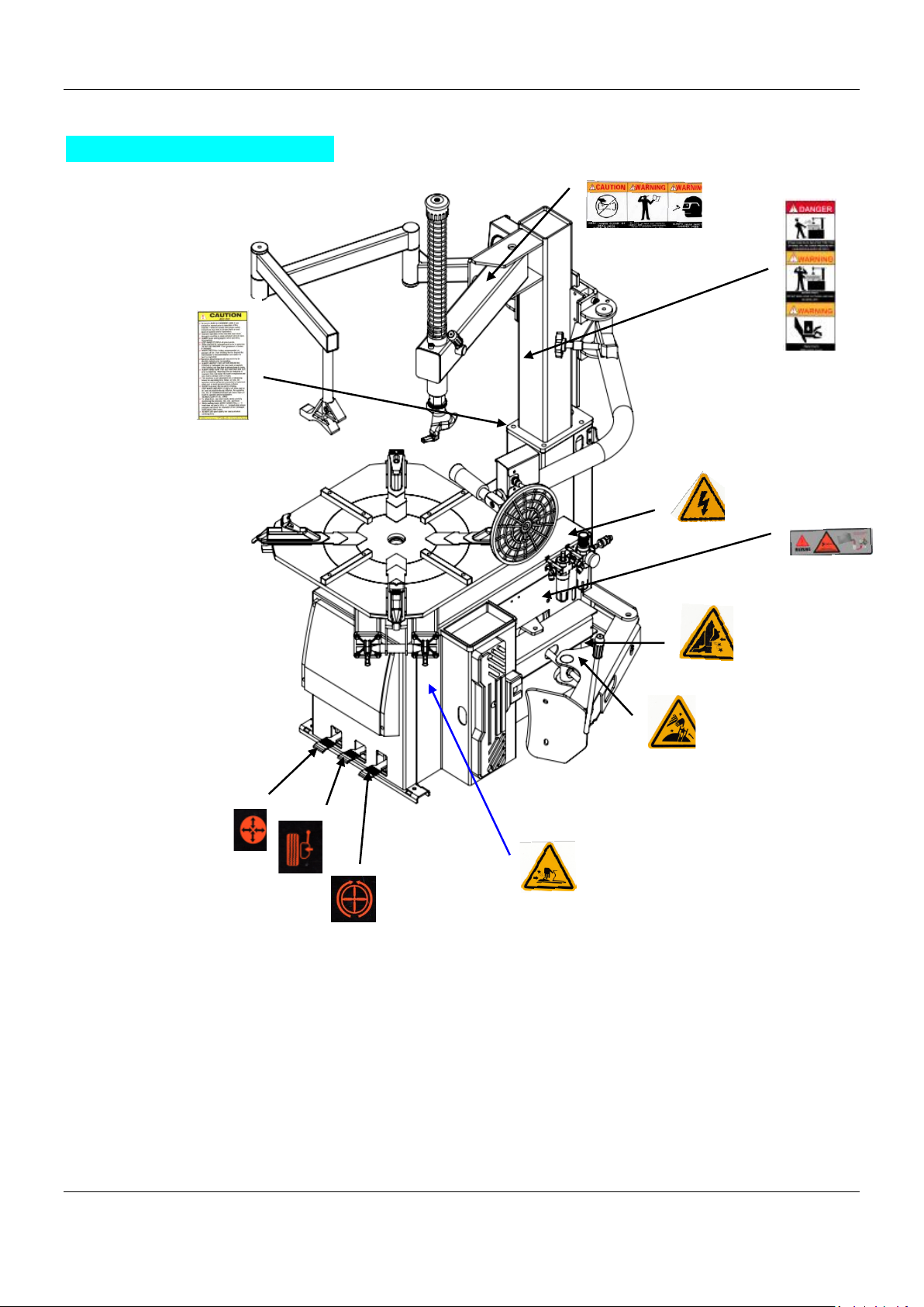
2.4 Figure and part name
G:Wheel Clamp
P:column
U:Bead Breaker pedal
I:mounting / dismounting head
R:Bead Breaker
Z:reversing pedal of table
M: Bead Breaker Pad
Y: turntable
N: horizontal pendulum arm
T: Bead Lifting Tool
K: locking handle
Q: oil water separator
Page 13

Aston® Tire Changer ATC-5800 User’s Manual |
13
www.astontechusa.com
V1, V2: Wheel Clamp Pedal
C: Turbo Blast Hose Assembly
E: hand wheel
E
K
C
P
N
I
G
Y
R
Z
U
V2
V1
Q
M
Page 14

Aston® Tire Changer ATC-5800 User’s Manual |
14
www.astontechusa.com
Installation and commissioning instructions
3.1 Installation Preparation
3.1.1 Installation location
·The area should provide the operator with enough space to use the equipment in a safe
manner.
·The area selected should be well lit, easy to clean and should be away from oil, grease,
brake lathe chips, etc. Avoid areas where bystanders and customers may be present.
·Equipment installation location should be at least up to the standard shown in Picture,
which can ensure the normal operation and the machine parts are not subject to any
restrictions. The tire changer is forbidden to use in explosive gas.
Page 15

Aston® Tire Changer ATC-5800 User’s Manual |
15
www.astontechusa.com
3.1.2 Installation equipment and tools
◇ Installation equipment and tools
3.1.3 Inspection products
◇ The shipment should be thoroughly inspected as soon as it is received. The signed Bill
of Lading is acknowledgement by the shipping carrier as receipt of this product as listed
in your invoice as being in a good condition of shipment. If any of these goods listed on
this Bill of Lading are missing or damaged, do not accept goods until the shipping carrier
makes a notation on the freight bill of the missing or dam- aged goods. Do this for your
own protection.
3.1.4 Unpacking
◇ Check the packaging damage and
the rain and other damage
phenomenon, using the tool unpack
the packing as shown in Picture,
please dispose of packaging box,
lest the environmental pollution.
◇ Check the condition of the machine,
in accordance with the packing list
to check if there is any damage or
lost, once found contact the dealer
and manufacture immediately. If
you find that the leakage but still installed, we will not assume any responsibility. If you
have any questions, please do not use the machine, the supplier contact.
3.2 Precautions during installation
◇ All bolts must be tightened.
◇ Power cord, no broken skin, no broken pipe, and other damage.
Figure 5
Page 16

Aston® Tire Changer ATC-5800 User’s Manual |
16
www.astontechusa.com
3.3 Main installation procedure
3.3.1 Standard configuration installation
◆ The first step: unscrew wooden pallet fixing screws, tire changer placed at the
installation site. (installation site must conform to the requirements.
◆ The second step: unscrewing the bolts from the box, the column is installed in the
machine box on the specified position, tighten the bolts.
◆ The third step: Fix the inflation box on the left side of tower with box.
◆ The forth step: Fix the turbo blast tank at back of machine box with box and connect its
nozzle on the left it with the given pipe in the back of machine.
Page 17

Aston® Tire Changer ATC-5800 User’s Manual |
17
www.astontechusa.com
3.4 Check the project table after installation
No.
Inspection item
Yes
No
Remarks
1
Whether the power supply voltage is consistent
with the requirements of the equipment
2
Whether the components are installed correctly
3
Whether the bolts, screws, nuts are tightened
Note: Please fill in the inspection item list after the installation is finished.
3.5 Commissioning and debugging
3.5.1 Commissioning
◇ After the installation of the machine but before the connection with the power supply, it
is necessary to determine the user's power supply, the gas source and the requirements
of the machine is consistent.
◇ The machine is connected to the circuit, the circuit must be fitted with a fuse that is in
line with the operating rules. The automatic circuit breaker of 25A is required to be
operated by professional personnel. The power plug of the tire changer is provided with
the customer.
◇ The compressed air system is connected to the machine by a pipe joint on the right side
of the tank.
3.5.2 Debugging
◇ Step 1: turn on the power and gas supply, depress the Turntable Rotation pedal, turntable
should be clockwise. Raise the Turntable Rotation pedal, the turntable should be anti-
clockwise rotation. (If the turntable is opposite to the specified rotation direction, the
position of the two lines in the three-phase plug should exchange position.)
◇ The second step: depress the Bead Breaker Pedal, start the Bead Breaker device; when
the pedal is released, the Bead Breaker device to return to the original position.
◇ The third step: depress the Jaw Clamp Pedal, open the 4 clamps; release the Jaw Clamp
Pedal, the Jaw Clamps returns to the original position.
◇ The forth step: Swing Arm / Vertical Shaft / Mount-Demount Head Assembly
Page 18

Aston® Tire Changer ATC-5800 User’s Manual |
18
www.astontechusa.com
Operation
Operation
4.1 Operating notes
◇ Check the connection of air pipe is in place, ensure that no air leakage, ensure the
operation space to meet the requirements, then start work.
◇ Before any operation, the gas in the tire is needed to be released, and the balance block
of the tire balancing device is removed.
4.2 Disassemble operation process
4.2.1 Bead Loosening
◇ Deflate tire completely by removing the valve core from the valve stem. To avoid
damaging the clamps and/or wheel, move the clamps to their full inward position before
positioning a tire for bead loosening.
◇ Pull the bead breaker blade away from the machine and roll the wheel into position. If
servicing a performance wheel or any other wheel with Tire Pressure Sensor), make sure
that the valve stem is either in the 12 o’clock or 6 o’clock position.
◇ Position the bead breaker blade against the tire next to, but not on, the rim or the sidewall
of the tire. Press the breaker pedal to actuate the blade and loosen the bead. It may be
necessary to loosen the bead in multiple locations around the tire. Use extra care in
⚫ Raise the Vertical Shaft / Mount-demount head
assembly to the highest position and lock it in
place by pushing the Locking Handle up.
⚫ Check the Socket Head Cap Screw on the Cap,
tighten if necessary.
⚫ Check the operation of the Vertical Shaft and
the Locking Handle.
Page 19

Aston® Tire Changer ATC-5800 User’s Manual |
19
www.astontechusa.com
positioning the bead breaker blade on larger wheels/tires, and on alloy wheels.
◇ Turn wheel around and repeat procedure on the other side of the wheel. This should be
the long side of the drop center. It will be easier to clamp the wheel to the table top if
the lower bead is loosened last.
⚫ Determine the mounting side of the wheel. The mounting side is the narrow side of the
drop center.
4.2.2 Wheel Clamping
◇ Place the Wheel Protector pads on the
Wheel Clamps if desired when
clamping from the outside.
◇ Place tire/wheel assembly on Table
Top with mounting side up.
Page 20

Aston® Tire Changer ATC-5800 User’s Manual |
20
www.astontechusa.com
◇ Use the Wheel Clamp Foot Pedal to move the Clamps inward (pedal down) or outward
(pedal up).
4.2.3 Tire mounting
◇ Apply tire manufacturer’s approved rubber lubricant liberally to entire circumference of
both upper and lower beads after loosening bead and placing on table top.
◇ After the wheel is secured to the Turntable, swing the Vertical Arm into position. Use
the large adjusting Knob to position the Mount/Demount Head directly over the edge of
the rim.
◇ Push the Vertical Shaft down and position the Mount/ Demount Head into contact with
the rim edge.
◇ Pull the locking handle towards you to lock the Vertical Shaft into position. As the slide
is locked, the Mount/ Demount Head will move upward approximately 1/8 inch and
backward 1/8 inch from the rim edge. The Mount/Demount head roller should not be in
contact with the rim edge.
◇ Place tire/wheel assembly on Table Top with mounting side up.
Page 21

Aston® Tire Changer ATC-5800 User’s Manual |
21
www.astontechusa.com
◇ Rotate the wheel using the Turntable Pedal until the valve stem is at the 3 o’clock
position in relation to the Mount/Demount Head.
◇ Insert the smooth curved end of the Bead Lifting Tool over the tab side of the
Mount/Demount Head and below the top bead of the tire.
◇ Push the Bead Lifting Tool down and away from the wheel to lower the bead into the
Drop Center while lifting up on the Table Top Pedal to rotate the turntable counter
clockwise.
NOTE:
THIS CLEARANCE WILL BE MAINTAINED AS LONG AS THE VERTICAL SHAFT REMAINS
LOCKED. THE OPERATOR MAY SWING THE ARM OUT OF THE WAY AND BACK INTO PLACE
AGAIN WITHOUT NEEDING TO REPOSITION THE HEAD WHEN CHANGING A LIKE SET OF
WHEELS. THE TOOL CLEARANCE MAY CHANGE WITH MACHINE USE AND SHOULD BE
INSPECTED OFTEN. FAILURE TO MAINTAIN PROPER CLEARANCE MAY RESULT IN DAMAGE
TO THE WHEEL RIM OR TIRE.
THE BEAD LIFTING TOOL AND DEMOUNT HEAD MAY ENCOUNTER RESISTANCE OR COME
UNDER LOAD AT TIMES DURING THE MOUNT AND DEMOUNT PROCEDURES. KEEP ONE HAND
FIRMLY ON THE TOOL TO AVOID POSSIBLE TOOL KICK BACK. USE THE REVERSING FEATURE
(LIFT TABLE TOP PEDAL UPWARDS) TO BACK OUT OF JAM UPS.
Page 22

Aston® Tire Changer ATC-5800 User’s Manual |
22
www.astontechusa.com
◇ Push the Bead Lifting Tool down toward the wheel to lift the tire bead up and over the
tab of the demount head. Hold the Bead Lifting Tool in this position. Depress the Table
Top Foot Pedal to rotate the wheel clockwise.
◇ Hold the Bead Lifting Tool down until the upper bead is solidly above the rim. Continue
rotating the wheel clockwise until the upper bead is completely demount.
◇ Liberally lubricate the lower bead again, if there was any difficulty lubricating the lower
bead earlier.
◇ Put the edge of the helper disc at the bottom of lower bead, lifting the bottom of tire up
by turn the control left. Lift and hold the tire so it is positioned with the lower bead in
the drop-center portion of the wheel.
◇ Insert the smooth curved end of the Bead Lifting Tool over the tab end of Mount /
Demount Head and below the lower bead of the tire. Push the Bead Lifting Tool down
toward the wheel to lift the tire bead up and over the left tab side knob portion of the
NOTE:
FOR LOW PROFILE TIRES, GET THE UPPER BEAD INTO THE DROP CENTER OF THE WHEEL.
Page 23

Aston® Tire Changer ATC-5800 User’s Manual |
23
www.astontechusa.com
Mount/ Demount Head. Hold the Bead Lifting Tool in this position.
◇ Depress the Table Top Pedal to rotate the wheel
◇ The Mount / Demount Head will guide the bead up and over the edge of the wheel.
Continue rotation until the lower bead is demount.
CUSTOM AND SPECIAL WHEELS
ALLOY WHEELS
IF A CUSTOM WHEEL IS DAMAGED WHILE DEMOUNTING, STOP, AND AVOID
DAMAGING THE OTHER WHEELS. CONTINUE ONLY WHEN THE CAUSE IS IDENTIFIED
AND CORRECTED.
Some manufacturers offer wheels with little or
no drop center. These are not DOT approved.
The tire or wheel - or both - can be damaged and
the tire could explode under pressure, resulting
in serious injury or death. If you attempt to
mount/demount this type of wheel, use extreme
caution.
Page 24

Aston® Tire Changer ATC-5800 User’s Manual |
24
www.astontechusa.com
WHEELS WITH TIRE PRESSURE WARNING SENSORS
◇ After both tire beads are loosened, try to remove the tube. If you cannot remove the tube lubricate the beads and rim
liberally.
DEMOUNTING TUBE TYPE TIRES
4.2.4 Demount Tube type tires
◇ After both tire beads are loosened, try to remove the tube. If you cannot remove the tube
lubricate the beads and rim liberally.
◇ Position the demount head and bead lifting tool as described earlier paying careful
attention not to pinch the tube. Depress the table top pedal and rotate only a short
distance at a time. This allows you to stop the process should you suspect the tube is
getting pinched.
◇ After upper bead is demount, remove tube and demount lower bead.
4.3 Mounting
◇ Inspect the wheel closely for damage. Clean the wheel and remove any light corrosion
or rubber residue. Do not attempt to service heavily corroded wheels.
REMEMBER:
TABLE TOP ROTATION CAN BE STOPPED AT ANY TIME BY REMOVING YOUR FOOT
FROM THE ROTA- TION PEDAL. NORMAL TABLE TOP ROTATION
FOR DEMOUNTING IS CLOCKWISE. DEPRESS THE TABLE TOP PEDAL TO ROTATE
THIS DIRECTION. TO ROTATE THE TABLE TOP COUNTERCLOCKWISE, LIFT THE
PEDAL UP WITH YOUR TOE.
Page 25

Aston® Tire Changer ATC-5800 User’s Manual |
25
www.astontechusa.com
◇ Inspect tire for damage, paying close attention to the beads. Verify size match between
tire and wheel.
◇ Lubricate both tire beads liberally with tire manufacturer’s approved lubricant.
THE RIM AND BEAD MUST BE LIBERALLY LUBRICATED. FAILURE TO USE AN
ADEQUATE LUBRICANT CAN LEAD TO THE BEAD BINDING ON THE RIM AND
LEAD TO DAMAGE TO THE MOTOR AND OR VOID THE WARRANTY.
THE INFORMATION IN THIS SECTION MUST BE READ AND FOLLOWED
CAREFULLY TO PREVENT ACCIDENTS AND INJURIES DURING MOUNTING.
CHECK TIRE AND WHEEL CAREFULLY BEFORE MOUNTING. MAKE SURE THE
TIRE BEAD DIAMETER AND WHEEL DIAMETER MATCH EXACTLY. CONSULT THE
RUBBER MANUFACTURER’S ASSOCIATION FOR APPROVED RIM WIDTHS FOR
TIRE SIZES.
ATTEMPTS TO FORCE A BEAD SEAT ON MISMATCHED TIRES AND WHEELS CAN
CAUSE THE TIRE TO VIOLENTLY EXPLODE, LEADING TO SERIOUS PERSONAL
INJURY OR DEATH TO OPERATOR AND/OR BYSTANDERS.
NEVER MOUNT A TIRE AND WHEEL HANDED TO YOU BY ANYONE WITHOUT
CHECKING BOTH TIRE AND WHEEL FOR DAMAGE AND COMPATIBILITY. BE
EXTRA CAUTIOUS OF PERSONS WITHOUT KNOWL EDGE OF TIRE SERVICE. KEEP
BYSTANDERS OUT OF SERVICE AREA.
Page 26

Aston® Tire Changer ATC-5800 User’s Manual |
26
www.astontechusa.com
◇ Place tire over wheel and move Vertical Arm and Mount/ Demount Head into position
as described earlier.
◇ Manually push the tire down into the drop center of the wheel directly across from the
Mount/ Demount Head to reduce the tension force on the bead. Depress the Table Top
Pedal and rotate the wheel to begin mounting the lower bead. Rotate the Table Top until
the lower bead is fully mounted.
NEVER MOUNT A DAMAGED TIRE. NEVER MOUNT A TIRE ON A RUSTY OR
DAMAGED WHEEL. DAMAGED TIRES AND/OR WHEELS MAY EXPLODE.
IF YOU DAMAGE THE TIRE BEAD DURING MOUNTING, STOP! REMOVE THE TIRE
AND MARK IT AS DAMAGED. DO NOT MOUNT A DAMAGED TIRE.
NOTE:
THE FOLLOWING PROCEDURES SHOW THE ASSIST TOWER BEING USED; THE
TIRE CHANGER YOU ARE USING MAY NOT HAVE THE ASSIST TOWER
INSTALLED.
NOTE:
LOW PROFILE TIRES MAY REQUIRE USE OF THE BEAD LIFTING TOOL.
Page 27

Aston® Tire Changer ATC-5800 User’s Manual |
27
www.astontechusa.com
◇ Swing the Assist Tower into position and lower the Roller Arms so that they press down
on the tire to hold the upper bead in the drop center. The Upper Arm must be locked and
positioned next to the Mount-demount Head.
◇ Depress the Table Top Pedal. As the Turntable rotates the Lower Arm will follow the tire
around. Keep rotating the table until the bead is mounted
MOUNTING TUBE TYPE TIRES
◇ Lubricate the beads and rim liberally.
◇ Position the Mount/Demount Head as described earlier. Mount the bottom bead first.
◇ Apply rubber lubricant to the tube. Insert the tube into the tire, paying careful attention
not to pinch the tube. Round out the tube with a small amount of air.
◇ Lower the Arm Rollers onto the tire as described earlier.
◇ Round out the tube with a small amount of air. Apply rubber lubricant to the tube.
DO NOT FORCE THE TIRE ONTO THE RIM. BEAD DAMAGE COULD
RESULT MAKING THE TIRE UNSAFE AND/OR CREATING THE RISK OF
INJURY.
Page 28

Aston® Tire Changer ATC-5800 User’s Manual |
28
www.astontechusa.com
◇ Depress the Table Top Pedal and rotate only a short distance at a time.
◇ Mount the top bead.
INFLATION
Review the following descriptions and diagrams carefully. Refer to them as necessary during
wheel restraint, bead sealing, bead seating, and inflation to verify that you are proceeding
properly and safely.
◇ Position One - Tire Pressure - With the Inflation Hose attached to the tire valve and the
CHECK INFLATION GAUGE FOR PROPER OPERATION. ACCURATE PRESSURE
READINGS ARE IMPORTANT TO SAFE TIRE INFLATION. REFER TO THE
OPERATING MAINTENANCE SECTION OF THIS MANUAL FOR INSTRUCTIONS. IF
THE RIM HAS BEEN CLAMPED FROM THE OUTSIDE FOR TIRE MOUNT- ING,
RELEASE THE CLAMPS ONCE BEAD SEAL IS OBTAINED, LIFT THE TIRE, AND
MOVE THE CLAMPS TO THE CENTER OF THE TABLE TOP.
THE CLIP-ON AIR CHUCK ON THE END OF THE INFLATION HOSE AND ALL
INFLATION RELATED COMPONENTS SHOULD BE CHECKED WEEKLY FOR
PROPER OPERATION. DO NOT USE THIS MACHINE FOR TIRE INFLATION IF ANY
PARTS ARE DAMAGED OR APPEAR NOT IN PROPER WORKING ORDER.
TIRE FAILURE UNDER PRESSURE IS HAZARDOUS. THIS TIRE CHANGER IS NOT
INTENDED TO BE A SAFETY DEVICE TO CONTAIN EXPLODING TIRES, TUBES,
WHEELS, OR BEAD SEALING EQUIPMENT. INSPECT TIRE AND WHEEL
CAREFULLY FOR MATCH, WEAR, OR DEFECTS BEFORE MOUNTING. ALWAYS
USE APPROVED TIRE BEAD LUBRICANT DURING MOUNTING AND INFLATION.
Page 29

Aston® Tire Changer ATC-5800 User’s Manual |
29
www.astontechusa.com
pedal in this position, the air gauge will register the air pressure in the tire. Whenever
your foot is removed from the pedal, it will return to this position
◇ Tire Inflation - With the Inflation Hose attached to the tire valve and the pedal depressed,
line pressure can flow through the valve and into the tire for inflation. Tire pressure is
not indicated on the gauge in this position
Tire Inflation
◇ The unit is equipped with a Pressure Limiter/Regulator to assist the operator with proper
tire inflation. The Pressure Limiter will keep most car and light truck tires from inflating
beyond 60 PSI. It is the operator’s responsibility to follow all instructions and to control
inflation pressure as specified in these instructions.
CHECK THE FUNCTION OF THE PRESSURE LIMITER REGULARLY. MAINTAIN IT
ACCORDING TO THE INSTRUCTIONS PROVIDED IN THIS MANUAL FOR SAFE
AND PROPER OPERATION. DO NOT TAMPER WITH OR ATTEMPT TO ADJUST THE
PRESSURE LIMITER. TIRES REQUIRING INFLATION BEYOND 60 PSI SHOULD
ONLY BE INFLATED IN A SAFETY CAGE.
Page 30

Aston® Tire Changer ATC-5800 User’s Manual |
30
www.astontechusa.com
Stage of Inflation
BEAD SEALING
◇ Position valve stem in front of operator and connect the inflation hose after removing
the valve core
◇ Step on the inflation pedal to allow air to flow into the tire and seal the beads.
THIS MACHINE IS NOT INTENDED TO BE A RESTRAINING DEVICE FOR EXPLODING
TIRES, TUBES, OR RIMS. KEEP HANDS AND BODY CLEAR AT ALL TIMES AND AS FAR
BACK AS POSSIBLE DURING INFLATION. DO NOT LEAN OVER THE TIRE WHILE
INFLATING. AN EXPLODING TIRE, RIM OR OTHER WHEEL COMPONENT CAN
CAUSE DEATH TO OPERATOR AND/OR BYSTANDER. REMAIN CLEAR AT ALL TIMES.
THIS OBJECT IS A RESTRAINT DEVICE ONLY. IT WILL NOT PROTECT OPERATORS
IN THE EVENT OF CATASTROPHIC TIRE/WHEEL RUPTURE OR FAILURE. ALWAYS
USE EXTREME CAUTION DURING THE INFLATION PROCEDURE. AS AN ADDED
SAFETY PRECAUTION, SAFETY CAGES THAT CONFORM TO OSHA STANDARD
1910.177 ARE RECOMMENDED.
Page 31

Aston® Tire Changer ATC-5800 User’s Manual |
31
www.astontechusa.com
TO SEAL LOW PROFILE OR DIFFICULT BEADS, USE THE TURBO
BLAST TO SEAL THE BEAD
◇ To Open the Slide Valve, PUSH the Slide Valve Forward
◇ Close PULL the Slide Valve closed.
◇ Position the Turbo Blast Nozzle to the direct air towards the Rim Center just under the
Rim Lip.
◇ Depress inflation pedal and open the Turbo-Blast Valve for less than one full second.
The blast of air from the Turbo Blat Nozzle will expand tire and seal the beads.
NEVER POINT NOZZLE TOWARDS YOURSELF OR OTHER
PERSONS. INSPECT NOZZLE, TIRE AND WHEEL FOR
DEBRIS. NOZZLE MUST BE POINTED TOWARD TIRE BEAD
AREA. HOLD NOZZLE SECURELY WITH BOTH HANDS AT
ALL TIMES. NEVER OPERATE THE NOZZLE WITHOUT A
TIRE AND WHEEL POSITIONED ON THE TABLE. DIRT AND
DEBRIS COULD BE BLOWN INTO THE AIR WITH ENOUGH
FORCE TO INJURE THE OPERATOR OR BYSTANDERS.
“Closed”
Slide
Valve
Page 32

Aston® Tire Changer ATC-5800 User’s Manual |
32
www.astontechusa.com
◇ Repeat these steps if beads have not sealed. It will be necessary to wait a few seconds
for the air storage tank to recover before attempting again. If tire and wheel are properly
lubricated and operator cannot achieve bead seal after a few attempts, check to see if the
valve core has been be removed from the valve stem to allow more air flow into the tire
to assist with bead seal. After bead seal is achieved, remove the chuck and reinstall the
valve core.
BEAD SEATING
Bead seating usually occurs on the long-tapered side of the wheel first and the shorter side
last. Bead seating will usually require at least 7 PSI in the tire. 40 PSI is the maximum safe
pressure at this stage regardless of tire operating pressure. Most European import cars and
many aftermarket alloy wheels are very tight and can be difficult to bead seat. Also note that
asymmetrical hump and run-flat tires are extremely difficult to bead seat. Follow tire
manufacturer’s recommended procedure for bead seating.
◇ Once tire pressure is indicated on the air gauge (inflation pedal depressed, continue to
inject air into the tire in short intervals. Check the pressure frequently. Stand back during
bead seat. Keep hands, arms, and entire body away from tire during this procedure. Tire
beads should move outward and “pop” into their bead seat position as pressure inside
the tire increases. If this does not happen, a problem exists. Investigate carefully.
◇ Release air pressure from the tire by pressing the manual Pressure Relief Valve.
ERATOR SHOULD KEEP HANDS, ARMS, AND ENTIRE BODY AWAY FROM THE TIRE
DURING THE FOLLOW- ING BEAD SEAT AND INFLATION PROCEDURES. DO NOT
STAND OVER TIRE, AS PERSONAL INJURY COULD RESULT FROM INFLATING TIRE.
Page 33

Aston® Tire Changer ATC-5800 User’s Manual |
33
www.astontechusa.com
STAGE FOUR / TIRE INFLATION
◇ Make sure both beads are seated. When both beads are seated, the tire is ready for
inflation.
◇ Replace the valve core if it was removed.
CHECK TIRE PRESSURE FREQUENTLY. NEVER EXCEED 40 PSI WHILE SEATING
BEADS. ONCE SEATED, NEVER EXCEED TIRE MANUFACTURER’S RECOMMENDED
AIR PRESSURE. TIRES CAN EXPLODE, ESPECIALLY IF THEY ARE INFLATED
BEYOND THEIR LIMITS. AT ALL PRESSURE LEVELS WHEN INFLATING THROUGH
THE VALVE STEM, KEEP HANDS, ARMS, AND ENTIRE BODY AWAY FROM
INFLATING TIRE. AN EXPLODING TIRE, WHEEL, OR BEAD SEALING EQUIPMENT
MAY PROPEL UPWARD AND OUTWARD WITH SUFFICIENT FORCE TO CAUSE
SERIOUS INJURY OR DEATH TO OPERATOR OR BYSTANDER.
NEVER ATTEMPT TO MOUNT AND INFLATE MISMATCHED TIRES AND WHEELS.
MISMATCHED TIRE AND WHEEL COMBINATIONS CAN EXPLODE, CAUSING
PERSONAL INJURY OR DEATH TO OPERATOR AND BYSTANDERS. FOR SAFETY,
DO NOT ATTEMPT TO MOUNT AND INFLATE MISMATCHED TIRES AND WHEELS.
IF OPERATOR IS UNABLE TO OBTAIN BEAD SEAT, SOMETHING IS WRONG. DEFLATE
TIRE COMPLETELY, INSPECT TIRE AND WHEEL, CORRECT ANY PROBLEMS FOUND,
RE-LUBRICATE BOTH TIRE BEADS, AND REATTEMPT BEAD SEAL AND SEAT
PROCEDURES. FOLLOW ALL SAFETY INSTRUCTIONS IN THIS MANUAL AND ON
MACHINE
Page 34

Aston® Tire Changer ATC-5800 User’s Manual |
34
www.astontechusa.com
◇ Depress the Inflation Pedal to inflate the tire. DO NOT STAND OVER TIRE DURING
INFLATION.
◇ Do not inflate the tire above the manufacturer’s recommended pressure as stamped on
the tire sidewall. The typical inflation pressure for automobile tires is between 24 and
45 PSI. Light truck inflation pressure typically covers a wider range. Release air pressure
from the tire by pressing the manual Pressure Relief Valve
NOTE:
WHEN INFLATING TIRES THAT REQUIRE MORE THAN 60 PSI, ALWAYS USE A
SAFETY CAGE AND AIR HOSE WITH A CLIP-ON AIR CHUCK AND IN-LINE VALVE.
THE HOSE MUST HAVE ENOUGH LENGTH BETWEEN THE CHUCK AND THE
OPERATION/IN-LINE VALVE TO ALLOW THE TECHNICIAN TO STAND OUTSIDE
THE TRAJECTORY
CHECK TIRE PRESSURE FREQUENTLY. NEVER EXCEED 40 PSI WHILE SEATING
BEADS. ONCE SEATED, NEVER EXCEED TIRE MANUFACTURER’S
RECOMMENDED AIR PRESSURE. TIRES CAN EXPLODE, ESPECIALLY IF THEY
ARE INFLATED BEYOND THEIR LIMITS. AT ALL PRESSURE LEVELS WHEN
INFLATING THROUGH THE VALVE STEM, KEEP HANDS, ARMS, AND ENTIRE
BODY AWAY FROM INFLATING TIRE. AN EXPLODING TIRE, WHEEL, OR BEAD
SEALING EQUIPMENT MAY PROPEL UPWARD AND OUTWARD WITH SUFFICIENT
FORCE TO CAUSE SERIOUS INJURY OR DEATH TO OPERATOR OR BYSTANDER.
Page 35

Aston® Tire Changer ATC-5800 User’s Manual |
35
www.astontechusa.com
Maintenance
5.1.1 Maintenance
◇ Prohibit unauthorized personnel for maintenance operation. To extend the service life of
the tire changer, maintenance should be performed according to the requirements of the
manual. If the machine is not maintained regularly, the operation and reliability cannot
be guaranteed, and even cause danger to the operator or the people in the vicinity of the
machine. Before any maintenance operation, circuit and gas supply device must be
disconnected, turn off the switch. In order to release the pressure of the air from the line,
it is necessary to press the pedal 3-4 times.
◇ It must be professional staff using the original spare parts do the timely replacement of
damaged parts. The safety device (safety valve, control valve) of the unauthorized
removal or replacement is a violation of state regulations on work safety. (Note: the
manufacturer is not responsible for damage caused by the parts of other manufacturer
and the damage caused by the disassembling of the safety device).
5.1.2 Tending
◇ Regular use of diesel oil to clean the turntable, to prevent the formation of dirt. Daub
lubricating oil in the skidway of the clamps.
◇ As shown in figure 15-a, control oil mist level that in the oil mist device, if the oil level
WEAR PROTECTIVE CLOTHING AND USE EYE PROTECTION WHEN MAKING
ANY ADJUSTMENTS OR REPAIRS TO THE MACHINE.
BEFORE MAKING ANY INSPECTION
ADJUSTMENT, OR REPAIR, DISCONNECT THE POWER SOURCE AND OR AIR
SUPPLY AND BLOCK OUT ALL MOVING PARTS TO PREVENT INJURY.
KEEP THE MACHINE AND THE IMMEDIATE WORK AREA CLEAN. DO NOT USE
COMPRESSED AIR TO REMOVE DIRT AND DEBRIS FROM THE MACHINE.
FOREIGN MATERIAL MAY BE PROPELLED INTO THE AIR AND INTO OPERATOR
OR BYSTANDER CAUSING PERSONAL INJURY.
Page 36

Aston® Tire Changer ATC-5800 User’s Manual |
36
www.astontechusa.com
is lower, you need to unscrew the oil F, and then as figure 15-a., control oil mist level,
HG ISO and viscosity of VG32 ISO type oil mist is recommended. (like:ESSO Febis
K32,MOBIL Acauline 1405,KLUBER32). when stepping the pedal 3 to 4 times, check
whether there are oil drops into the oil cup F, if not, adjust screw D.
◇ As shown in figure 15-b, 20 days after the first use of the machine, re-tighten the screw
A and B that is in the clamps.
◇ As shown in figure 15-c, machine horsepower is not enough, check the triangle belt of
the motor by the following steps: (before any operation, to cut off the power) first,
Unscrew the 4 screws on the side of the box, remove the left side protective plate of the
tire changer, second, use special adjustment screw X (Figure 15-c) that is in the motor
support base to adjust the triangle belt.
◇ As shown in figure 15-d, If the (I) lock is not good or cannot be stopped at the top of the
2mm, it is necessary to adjust the nut on the operating arm.
◇ As shown in figure 15-e, when cleaning or replacing silencer which controls the opening
or closure of the clamps(G), follow the following steps: first, unscrew the 4 screws on
the side of the box, remove the left side protective plate on the tire changer. Second, in
the pedal (V1, V2) system which controls the opening or closure of the clamps(G),
unscrew silencer. Clean with compressed air nozzle, if damaged, replace with the same
parts.
Page 37

Aston® Tire Changer ATC-5800 User’s Manual |
37
www.astontechusa.com
Figure 15-b
Figure 15-a
Figure 15-c
Figure 15-d
Figure 15-e
Page 38

Aston® Tire Changer ATC-5800 User’s Manual |
38
www.astontechusa.com
5.2 Storage and scrap
5.2.1 Storage
◇ If you want a long-time storage of machine, please disconnect all the energy supply, and
lubricate the skidway of the clamps on the turntable to prevent oxidation.
5.2.2 Scrap
◇ In accordance with the law of the metal and nonmetal for scrap processing. In the
specified place release the oil inside the machine.
Fault causes and Solutions
Note: if you cannot solve the failure, please contact the manufacturer to provide help. We
will be the first time to help you to solve the failure. Provide the relevant fault information
and fault pictures, thus the manufacturer can get rid of the trouble at the fastest speed.
Failure phenomenon
Failure cause
Resolvent
Unidirectional rotation
of the turntable
Universal steering switch
damage
Replace universal steering
switch
Rotary table does not
rotate
Triangle damage
Replace triangle belt
Universal steering switch
damage
Replace universal steering
switch
Motor fault or line fault
Check motor and external plug
or socket
Rotary clamp opening /
closing speed is slow
Muffler blockage
Clean or replace muffler
The turntable can't lock
Clamps have trouble
Replace clamps
Page 39

Aston® Tire Changer ATC-5800 User’s Manual |
39
www.astontechusa.com
the rim correctly
Rotary cylinder has trouble
Replace cylinder or repair
cylinder sealing ring
Working head can touch
the rim
Lock plate adjustment is not
correct or faulty
Adjust or replace the locking
plate (Figure 18/d)
Working head screw loose
Tighten screws (Figure 12/a)
The pedal is not located
at work position.
Return spring has trouble
Replace return spring
Operating difficulties of
the tire device
Muffler blockage
To clean or replace the silencer
(Figure 18/f)
Cylinder sealing ring damage
of pressure device
Replace sealing ring
Page 40

Aston® Tire Changer ATC-5800 User’s Manual |
40
www.astontechusa.com
Parts List and Exploded Drawings
580A100
Box Unit Weldment
1
580A200
Tower Unit Weldment
2
5803000
Swing Arm ASSY
3
730
Turntable ASSY
4
380
Body of 380
5
Page 41

Aston® Tire Changer ATC-5800 User’s Manual |
41
www.astontechusa.com
1003510
Cylinder
6
1003000
Piston
7
5621012
Wheel Support Pad
8
8807000
Gear Box ASSY
9
6205100
Cylinder
10
6205200
Piston of Cylinder
11
8804000
Bead Breaker ASSY
12
8808002
Pedals
13
8521002
Classis Front Board
14
3012000
Oil and Water Separator
15
5704200
Inflation Box
16
6209000
Inflation Pedal
17
5754003
Bead Breaker Arm
18
3806008
Valve
19
580A108
hang hook
20
5621013
Lubricant Box
21
LIMITED WARRANTY
Aston® Wheel Service Equipment is warranted for the period of one year on all operating components to be free of
defects in material and workmanship. Aston® shall repair or replace at their option for the warranty period those
parts returned to the factory freight prepaid which prove upon inspection to be defective. Aston® will pay labor
costs for the first 12 months only on parts returned as previously described. These warranties do not extend to
defects caused by ordinary wear, abuse, misuse, shipping damage, improper installation or lack of required
maintenance. This warranty is exclusive and in lieu of all other warranties expressed or implied. In no event shall
Aston® be liable for special, consequential or incidental damages for the breach or delay in performance of the
warranty. Aston® reserves the right to make design changes or add improvements to its product line without
incurring any obligation to make such changes on product sold previously. Warranty adjustments within the above
stated policies are based on the model and serial number of the equipment. This data must be furnished with all
warranty claims.
 Loading...